1
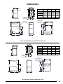
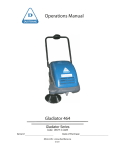
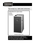
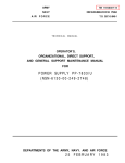
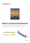
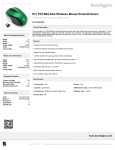
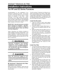
TECHNICAL
SPECIFICATIONS
FG7T (A and K Series)
, Smartlite
®
Two Stage, Fixed Speed,
High Efficiency Upflow/Horizontal
and Downflow Gas Furnaces
Induced Draft - 80 + AFUE
Input 60,000 - 140,000 Btuh
The high efficiency gas furnace may be installed free
standing in a utility room, basement, or enclosed in an
alcove or closet. The rounded corner jacket provides a
pleasing “appliance appearance.” Design certified by CSA
for application in Canada and the United States.
WARRANTY
– 10 ear
tswarranty.
– 10 Year Quality Pledge to replace the unit if the heat
exchanger fails within the first 10 years of operation, to
the original owner.
– Consumer product registration required for 10 year
All Parts Warranty and Quality Pledge within a limited
period of time after the installation. See current warranty
document or visit our consumer web site for warranty
details.
– When registered, this product is upgraded to a limited
lifetime heat exchanger warranty.
FEATURES and BENEFITS
• i SEER: Energy efficient brushless DC (ECM) motor
gives up to 1 SEER point efficiency gain in cooling.
• 100% fired and tested: All units and each component are tested on the manufacturing line.
• Best packaging in the industry: Unique corner post
design assures product will arrive to the homeowner dent
free.
• Low Boy Height: Easy to apply in low ceiling applications,
works well with taller high SEER coils, easier to handle
and install.
• Tubular primary heat exchanger: Heavy gauge
aluminized steel heat exchanger assures a long life.
• 30 second blower delay at start-up: Assures a warm
duct temperature at furnace start-up. Adjustable blower
off settings (60, 90, 120 and 180 seconds).
• 30 second post purge: Increases life of heat
exchanger.
• Hot surface igniter: Innovative application of a silicon
nitride igniter. Utilizes proven Smartlite® technology.
• Color coded wire harness: Designed to fit the
components, all with quick-connect fittings for ease of
service and replacement.
• High static blowers: All models equipped with high static
blowers.
• 90 second cooling cycle blower-off delay (TDR):
Increases cooling performance when matched with a
NORDYNE coil.
• Flexible category I venting system: May be vented
with dedicated venting system or common vented with
other category one appliances.
• Variable speed blower kit: Upgradable to full variable
speed with kit.
• LP convertible: Simple burner orifice and regulator spring
change for ease of convertibility.
• Diagnostic lights for easy troubleshooting without
counting flashes: Dedicated light for flame signal
strength and 2 lights in combination to indicate all other
fault codes with easy to recognize states without counting
flashes.
• Integrated control board: Incorporates connections for
electronic air cleaner, humidifier and twinning.
• Two piece door design: Enhances furnace appearance
and uses captured screws to prevent loosing door
screws.
• Blower Compartment: Insulated for ultra quiet
operation.
• 2 Stage Inducer: Optimizes efficiency on first stage heat
and reduces sound levels.
GAS FURNACE COMPONENTS
10
11
8
1. Blower Assembly
6
2. Blower Door Switch
3. Burner Assembly
4. Flame Roll-Out Switch
5. Flame Sensor
16
9
15
6. Furnace Control Board
5
8. Gas Valve
2
7
4
3
7. Gas Manifold
9. Igniter
10. Inducer Assembly
11. Main Air Limit Switch
12. Motor Choke (3/4 and 1HP only)
1 2 3 4 56 78
12
1
13. Motor Control Board
13
15. Pressure Switch(s)
14
14. Motor Control Box
16. Transformer
Upflow/Horizontal Gas Furnace
1. Blower Assembly
4
7
13
1 2 3 4 5 6 78
14
2
3. Burner Assembly
4. Combustion Tube
5. Flame Roll-Out Switch
15
1
2. Blower Door Switch
16
11
9
6. Flame Sensor
7. Furnace Control Board
8. Gas Manifold
9. Gas Valve
10. Igniter
11. Inducer Assembly
12. Main Air Limit Switch
10
8
3
13. Motor Choke (3/4 and 1HP only)
14. Motor Control Board
15. Pressure Switch(s)
12
5
6
Downflow Gas Furnace
2
16. Transformer
DIMENSIONS
TOP VIEW
C
D
FRONT
BRACE
*TA
Model #’s
BOTTOM
PANEL
AN
S
ACCEPTS 4”
TYPE B
VENT PIPE
BOTTOM VIEW
19
GE
10
3/4
12
5/8
12
17 1/2
11
3/4
15
7/8
16 1/8
14
140-45D1
24
21
19 3/8
14
1/2
15 1/4
22 7/8
19
7/8
5/8
23 1/8
B
Ø 7/8 HOLE FOR
THERMOSTAT
25 3/8
1 5/8 X 3 1/2
HOLE FOR GAS
22 1/4
Ø 7/8 HOLE FOR
ELECTRIC
Ø 7/8 HOLE FOR
ELECTRIC
25
21 3/4
4 KNOCKOUTS
(BOTH SIDES)
29 1/2
22 1/2
34 1/2
1/4
060-23A1
080-24B1
100-24B1
100-35C1
120-35C1
23
15
1 1/4
22 3/4
23 1/2
FL
23
Dimension Dimension Dimension Dimension
“A”
“B”
“C”
“D”
1 5/8 X 3 1/2 X 45°
HOLE FOR
GAS
23
A
28
RIGHT SIDE
1
LEFT SIDE
FG7TA 80+ High Efficiency Upflow/Horizontal Series
TOP VIEW
C
D
*TK
Model #’s
FRONT
BRACE
FL
AN
GE
S
18 5/8
23
ACCEPTS 4”
TYPE B
VENT PIPE
BOTTOM VIEW
19
Dimension Dimension Dimension Dimension
“A”
“B”
“C”
“D”
060-23A1
080-24B1
100-24B1
100-35C1
120-35C1
14
1/4
10 3/4
17
1/2
11
140-45D1
24
21
3/4
14
1/2
15
1/4
12
5/8
15 7/8
19
3/8
22 7/8
12
7/8
16 1/8
19 5/8
23
1/8
B
Ø 7/8 HOLE
FOR THERMOSTAT
22 1/4
Ø 7/8 HOLE
FOR ELECTRIC
Ø 7/8 HOLE
FOR ELECTRIC
25 3/8
28
LEFT SIDE
29 1/2
1 5/8 X 3 1/2 HOLE
FOR GAS
1 5/8 X 3 1/2 X 45°
HOLE FOR GAS
22 1/2
22 1/2
34 1/2
25
7
7
A
RIGHT SIDE
FG7TK 80+ High Efficiency Downflow Series
3
BLOWER PERFORMANCE - FG7TA/TK
FG7TA/TK - 80% AFUE, Two Stage Gas Furnace
Model Number
External Static Pressure (in.w.c.)
Heating Motor Switch
Setting
0.1
0.2
0.3
0.4
0.5
0.6
0.7
0.8
Input
(Btuh) 1/5 2/6 3/7 4/8 CFM Rise CFM Rise CFM Rise CFM Rise CFM Rise CFM Rise CFM Rise CFM Rise
*TA/TK-060(C)-*A1 60000
*TA/TK-080(C)-*B1 80000
0
0
0
0
1
0
0
0
0
1
0
0
600
74
555
80
510
1
1
0
0
705
63
670
66
635
70
600
74
0
0
1
0
775
57
740
60
705
63
665
67
1
0
1
0
900
49
870
51
835
53
800
56
765
58
730
61
695
64
660
67
0
1
1
0
950
47
920
48
890
50
855
52
825
54
795
56
765
58
730
61
1
1
1
0 1000
44
970
46
940
47
910
49
880
51
850
52
820
54
790
56
0
0
0
1 1075
41
1045 43 1015 44
985
45
960
46
925
48
900
49
870
51
1
0
0
1 1110
40
1080 41 1055 42 1025 43 1000 44
975
46
945
47
920
48
0
1
0
1 1170
38
1140 39 1115 40 1090 41 1060 42 1035 43 1010 44
985
45
1
1
0
1 1210
37
1185 38 1160 38 1130 39 1105 40 1080 41 1055 42 1025 43
0
0
1
1 1520
29
1225 36 1200 37 1175 38 1150 39 1120 40 1095 41 1070 42
1
0
1
1 1305
34
1280 35 1255 35 1230 36 1205 37 1180 38 1155 38 1130 39
0
1
1
1 1350
33
1230 36 1305 34 1285 35 1260 35 1240 36 1215 37 1195 37
1
1
1
1 1440
31
1400 32 1365 33 1230 36 1295 36 1255 35 1220 36 1185 38
0
0
0
0
1
0
0
0
0
1
0
0
1
1
0
0
725
82
0
0
1
0
810
73
1
0
1
0
940
63
890
67
845
70
795
75
750
79
700
85
0
1
1
0
990
60
945
63
905
65
860
69
820
72
775
76
735
81
690
86
1
1
1
0 1055
56
1015 58
970
61
930
64
890
67
845
70
805
74
760
78
0
0
0
1 1135
52
1095 54 1055 56 1010 59
960
62
930
64
890
67
850
70
1
0
0
1 1185
50
1145 52 1105 54 1065 56 1030 58
990
60
950
62
910
65
0
1
0
1 1250
47
1210 49 1170 51 1135 52 1095 54 1055 56 1020 58
980
60
1
1
0
1 1290
46
1255 47 1220 49 1180 50 1145 52 1110 53 1075 55 1040 57
0
0
1
1 1315
45
1275 46 1240 48 1200 49 1160 51 1120 53 1085 55 1045 57
1
0
1
1 1350
44
1315 45 1280 46 1245 48 1205 49 1170 51 1135 52 1100 54
0
1
1
1 1390
43
1350 44 1315 45 1275 46 1240 48 1200 49 1160 51 1125 53
1
1
1
1 1420
42
1380 43 1345 44 1310 45 1270 47 1235 48 1200 49 1160 51
Notes:
1. Motor Switch Settings are for heating speeds using HEAT switches 1, 2, 3, & 4 and cooling speeds using COOL switches 5, 6, 7, & 8.
2. Two openings are recommended for airflows above 1600 CFM if the filter(s) is (are) adjacent to the furnace.
3. Data is shown without filter.
4. Temperature rises in the table are approximate. Actual temperature rises may vary.
5. Temperature rises that are shaded in grey are for reference only. These conditions are not recommended.
4
BLOWER PERFORMANCE - FG7TA/TK Continued
G7TA/TK - 80% AFUE, Two Stage Gas Furnace
Model Number
*TA100(C)-*B1
External Static Pressure (in.w.c.)
Heating Motor Switch
Setting
0.1
0.2
0.3
0.4
0.5
0.6
0.7
0.8
Input
(Btuh) 1/5 2/6 3/7 4/8 CFM Rise CFM Rise CFM Rise CFM Rise CFM Rise CFM Rise CFM Rise CFM Rise
0
0
0
0
905
82
890
83
805
92
780
95
1
0
0
0
980
76
930
80
900
82
835
89
980
76
915
820
90
800
93
715 104 670 111
0
1
0
0 1095
68
1015 73
81
895
83
870
85
810
91
765
97
1
1
0
0 1160
64
1100 67 1065 70 1035 72
995
74
940
79
895
83
865
86
0
0
1
0 1230
60
1195 62 1170 63 1110 67 1075 69 1060 70
995
74
970
76
1
0
1
0 1315
56
1275 58 1240 60 1195 62 1160 64 1140 65 1115 66 1075 69
0
1
1
0 1345
55
1310 57 1280 58 1250 59 1220 61 1190 62 1140 65 1115 66
100000 1
1
1
0 1445
51
1390 53 1350 55 1315 56 1280 58 1250 59 1230 60 1185 63
0
0
0
1 1490
50
1430 52 1420 52 1380 54 1340 55 1310 57 1280 58 1275 58
1
0
0
1 1550
48
1510 49 1475 50 1450 51 1420 52 1375 54 1340 55 1325 56
0
1
0
1 1600
46
1270 58 1540 48 1500 49 1475 50 1445 51 1425 52 1385 53
1
1
0
1 1640
45
1605 46 1570 47 1550 48 1525 49 1490 50 1460 51 1430 52
0
0
1
1 1690
44
1665 44 1630 45 1600 46 1570 47 1550 48 1515 49 1490 50
1
0
1
1 1755
42
1730 43 1680 44 1660 45 1640 45 1610 46 1575 47 1550 48
0
1
1
1 1805
41
1770 42 1740 43 1715 43 1690 44 1655 45 1645 45 1605 46
1
1
1
1 1860
40
1825 41 1790 41 1765 42 1745 42 1710 43 1695 44 1660 45
0
0
0
0 1125
66
1040 71
1
0
0
0 1205
61
1120 66 1040 71
0
1
0
0 1305
57
1225 60 1150 64 1070 69
1
1
0
0 1430
52
1350 55 1270 58 1190 62 1110 67 1030 72
0
0
1
0 1525
49
1450 51 1375 54 1300 57 1225 60 1150 64 1075 69 1000 74
1
0
1
0 1620
46
1540 48 1465 51 1390 53 1315 56 1240 60 1165 64 1090 68
*TA/TK-100(C)-*C1 100000
960
77
960
77
995
74
915
81
950
78
865
86
0
1
1
0 1695
44
1620 46 1545 48 1465 51 1390 53 1315 56 1235 60 1160 64
1
1
1
0 1770
42
1700 44 1630 45 1555 48 1485 50 1410 53 1340 55 1265 59
0
0
0
1 1875
40
1805 41 1730 43 1655 45 1580 47 1510 49 1435 52 1340 55
1
0
0
1 1905
39
1840 40 1775 42 1710 43 1640 45 1575 47 1510 49 1445 51
0
1
0
1 1980
37
1910 39 1845 40 1780 42 1715 43 1650 45 1580 47 1515 49
1
1
0
1 2025
37
1960 38 1895 39 1830 40 1765 42 1700 44 1635 45 1570 47
0
0
1
1 2085
36
2025 37 1960 38 1900 39 1840 40 1775 42 1715 43 1655 45
1
0
1
1 2135
35
2070 36 2010 37 1945 38 1880 39 1815 41 1750 42 1685 44
0
1
1
1 2200
34
2145 35 2090 35 2035 36 1980 37 1925 38 1870 40 1820 41
1
1
1
1 2280
32
2225 27 2170 34 2115 35 2065 22 2010 37 1955 38 1900 39
Notes:
1. Motor Switch Settings are for heating speeds using HEAT switches 1, 2, 3, & 4 and cooling speeds using COOL switches 5, 6, 7, & 8.
2. Two openings are recommended for airflows above 1600 CFM if the filter(s) is (are) adjacent to the furnace.
3. Data is shown without filter.
4. Temperature rises in the table are approximate. Actual temperature rises may vary.
5. Temperature rises that are shaded in grey are for reference only. These conditions are not recommended.
5
BLOWER PERFORMANCE - FG7TA/TK Continued
FG7TA/TK - 80% AFUE, Two Stage Gas Furnace
Model Number
External Static Pressure (in.w.c.)
Heating Motor Switch
Setting
Input
0.1
0.2
0.3
0.4
0.5
0.6
0.7
0.8
(Btuh)
1/5 2/6 3/7 4/8 CFM Rise CFM Rise CFM Rise CFM Rise CFM Rise CFM Rise CFM Rise CFM Rise
*TA/TK-120(C )-*C1 120000
*TA/TK-140(C)-*D1 140000
0
0
0
0 1125
79
1040
1
0
0
0 1205
74
1120 79 1040 85
0
1
0
0 1305
68
1225 73 1150 77 1070 83
1
1
0
0 1430
62
1350 66 1270 70 1190 75 1110 80 1030 86
0
0
1
0 1525
58
1450 61 1375 65 1300 68 1225 73 1150 77 1075 83 1000 89
1
0
1
0 1620
55
1540 58 1465 61 1390 64 1315 68 1240 72 1165 76 1090 82
0
1
1
0 1695
52
1620 55 1545 58 1465 61 1390 64 1315 68 1235 72 1160 77
1
1
1
0 1770
50
1700 52 1630 55 1555 57 1485 60 1410 63 1340 66 1265 70
0
0
0
1 1875
47
1805 49 1730 51 1655 54 1580 56 1510 59 1435 62 1340 66
1
0
0
1 1905
47
1840 48 1775 50 1710 52 1640 54 1575 56 1510 59 1445 62
0
1
0
1 1980
45
1910 47 1845 48 1780 50 1715 52 1650 54 1580 56 1515 59
1
1
0
1 2025
44
1960 45 1895 47 1830 49 1765 50 1700 52 1635 54 1570 57
0
0
1
1 2085
43
2025 44 1960 45 1900 47 1840 48 1775 50 1715 52 1655 54
1
0
1
1 2135
42
2070 43 2010 44 1945 46 1880 47 1815 49 1750 51 1685 53
0
1
1
1 2200
40
2145 41 2090 43 2035 44 1980 45 1925 46 1870 48 1820 49
1
1
1
1 2280
39
2225 40 2170 41 2115 42 2065 43 2010 44 1955 45 1900 47
0
0
0
0 1395
74
1350 77 1305 79 1260 82 1210 86 1165 89
1
0
0
0 1465
71
1420 73 1375 75 1330 78 1290 80 1245 83 1200 86
0
1
0
0 1555
67
1510 69 1470 71 1425 73 1380 75 1340 77 1295 80 1250 83
1
1
0
0 1625
64
1585 65 1540 67 1500 69 1460 71 1415 73 1375 75 1335 78
0
0
1
0 1690
61
1650 63 1610 64 1570 66 1530 68 1485 70 1445 72 1405 74
1
0
1
0 1760
59
1715 60 1670 62 1625 64 1575 66 1530 68 1485 70 1440 72
0
1
1
0 1835
57
1790 58 1745 59 1695 61 1650 63 1605 65 1555 67 1510 69
1
1
1
0 1885
55
1840 56 1790 58 1745 59 1700 61 1655 63 1610 64 1565 66
0
0
0
1 1945
53
1900 55 1850 56 1805 57 1760 59 1710 61 1665 62 1620 64
1
0
0
1 1950
53
1905 54 1860 56 1820 57 1775 58 1735 60 1690 61 1650 63
0
1
0
1 2075
50
2030 51 1990 52 1945 53 1900 55 1855 56 1810 57 1770 59
1
1
0
1 2125
49
2085 50 2040 51 2000 52 1955 53 1910 54 1870 55 1825 57
0
0
1
1 2170
48
2130 49 2090 50 2045 51 2005 52 1965 53 1925 54 1880 55
1
0
1
1 2215
47
2180 48 2140 48 2105 49 2070 50 2035 51 2000 52 1965 53
0
1
1
1
2225 47 2165 48 2100 49 2040 51
1
1
1
1
2170 48 2120 49 2065 50
Notes:
1. Motor Switch Settings are for heating speeds using HEAT switches 1, 2, 3, & 4 and cooling speeds using COOL switches 5, 6, 7, & 8.
2. Two openings are recommended for airflows above 1600 CFM if the filter(s) is (are) adjacent to the furnace.
3. Data is shown without filter.
4. Temperature rises in the table are approximate. Actual temperature rises may vary.
5. Temperature rises that are shaded in grey are for reference only. These conditions are not recommended.
6
MODEL IDENTIFICATION CODE
FG
7
T
A
080
C
23
B
Gas Furnace
1
Revision Level
Design Series
Cabinet Width
A = 14.25
B = 17.50
C = 21.00
D = 24.50
S = Single Stage
T = Two Stage
M = Modulating
A = 80% Upflow/Horizontal
C = 92.1% / 95.1% Upflow/Horizontal
K = 80% Downflow
L = 92.1% / 95.1% Downflow
Q = 96.4+% AFUE Upflow/Horizontal
Cooling Airflow
23 = 2-3 Tons
24 = 2-4 Tons
35 = 3-5 Tons
45 = 4-5 Tons
V = VSB
Input Heating Capacity
060 = 60,000
080 = 80,000
100 = 100,000
120 = 120,000
140 = 140,000
C = Standard
D = 90+% AFUE Low NOx
SPECIFICATIONS
FG7TA/TK
MODEL NUMBERS
060C-23A1
080C-24B1
100C-24B1
100C-35C1
120C-35C1
140C-45D1
Input - Btuh (a)
60,000 / 39,000 80,000 / 52,000 100,000 / 65,000 100,000 / 65,000 120,000 / 78,000 140,000 / 91,000
Heating Capacity - Btuh
48,000 / 31,200 64,000 / 41,600 80,000 / 52,000 80,000 / 52,000 96,000 / 62,400
AFUE
Blower D x W
112,000 / 72,800
80.0
80.0
80.0
80.0
80.0
80.0
10 x 6
11 x 8
11 x 8
11 x 10
11 x 10
11 x 10
1/2 - BLDC
1/2 - BLDC
3/4 - BLDC
3/4 - BLDC
3/4 - BLDC
1 - BLDC
Motor FLA
6.2
6.2
8.7
8.7
8.7
11.7
Rated Ext. SP - In. W.C.
0.5
0.5
0.5
0.5
0.5
0.5
Temperature Rise Range - ºF
25-55
30-60
30-60
35-65
35-65
40-70
Shipping Weights
115lbs
110lbs
120lbs
125lbs
135lbs
155lbs
Motor H.P. - Speed - Type
All models are 115 V, 60 HZ. Gas connections are 1/2" N.P.T.
AFUE= Annual Fuel Utilization Efficiency
7
ACCESSORIES
FG7TA/TK KITS
Description
SKU
Fixed speed -to- variable speed
904880
"A" Cabinet downflow sub base kit
902974
"B", "C", "D" Cabinet downflow sub base kit
904911
U.S. LP Conversion kit (0 to 10,000 ft.)
904914
Canada LP Conversion kit (0 to 4,500 ft.)
904915
Bottom return filter 20 per box, "A" cabinet
903088
Bottom return filter 20 per box, "B" cabinet
904916
Bottom return filter 20 per box, "C" cabinet
904917
Bottom return filter 20 per box, "D" cabinet
904918
Side return filter kit
541036
GENERAL TERMS OF LIMITED WARRANTY
NORDYNE will furnish a replacement for any part of this product which fails in normal use and service within the
first ten years of installation, in accordance with the terms of the warranty.
For complete details of the Limited Warranty, including applicable terms and conditions, see your local installer or
contact the NORDYNE warranty department for a copy.
8000 Phoenix Parkway | O'Fallon, MO 63368-3827
Specifications and illustrations subject to change without notice and without incurring obligations. Printed in U.S.A (02/2010)
819C-0210 (Replaces 819C-1009)