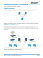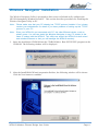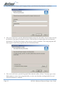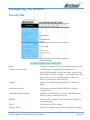
1
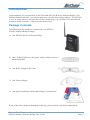
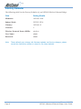
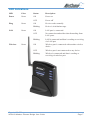
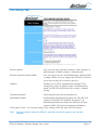
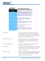
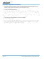
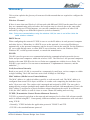
Contents
Introduction .................................................................................................................... 3
Package Contents ........................................................................................... 3
The NP5410 Wireless Ethernet Bridge Features ......................................................... 4
Wireless Features ...........................................................................................
LAN Features ...................................................................................................
Configuration & Management .........................................................................
Security .............................................................................................................
4
4
4
4
Physical Details ............................................................................................................. 5
Rear Panel ....................................................................................................... 5
Factory Defaults ............................................................................................... 6
LED Indications ............................................................................................... 7
Hardware Installation .................................................................................................... 8
Connecting the NP5410 to Your Network ........................................................ 9
Wireless Navigator Installation .................................................................................... 11
Startup and Login ........................................................................................... 14
Configuring the NP5410 ............................................................................................. 15
The Info Tab ...................................................................................................
The Setup Tab ................................................................................................
The Security Tab ............................................................................................
The Admin Tab ...............................................................................................
Firmware Upgrade Procedure .......................................................................
15
17
18
20
22
FAQ & Troubleshooting ............................................................................................... 23
Glossary ...................................................................................................................... 25
Product Specifications ................................................................................................. 27
Registering your NetComm Product ........................................................................... 28
Trademarks and Notices ............................................................................................ 28
Warranty Registration Form .......................................................................... 29
Product Warranty ............................................................................................ 31
Limitations of Warranty .................................................................................. 31
www.netcomm.com.au
Page 2
Rev. 1 - YML675
NP5410 Wireless Ethernet Bridge User Guide
Introduction
Congratulations on your purchase of the NetComm NP5410 Wireless Ethernet Bridge. This
Ethernet Adapter provides you with an innovative wireless networking solution. The NP5410
is easy to set up and use, and with this wireless technology, you can share files and network
resources on the network—without inconvenient wires!
Package Contents
The following items should be contained in your NP5410
Wireless Ethernet Bridge Package:
❏ One NP5410 Wireless Ethernet Bridge
❏ One CD-ROM (Wireless Navigator utility software & user’s
manual included)
❏ One RJ-45 straight LAN Cable
❏ One Power Adapter
❏ One Quick Installation Guide and Package Contents Note.
If any of the above items are damaged or missing, please contact your dealer immediately.
Rev. 1 - YML675
NP5410 Wireless Ethernet Bridge User Guide
www.netcomm.com.au
Page 3
The NP5410 Wireless Ethernet Bridge Features
Wireless Features
11g Standards Compliant
The NP5410 complies with IEEE802.11g, and it is
interoperable with IEEE802.11g-Compliant Equipment
Interoperable with IEEE802.11b
Backward compatible with IEEE802.11b equipments
Data Rate Auto Fall-Back
Provides 54, 48, 36, 24,12, 11, 9, 6, 5.5, 2 and 1Mbps
wireless data rate shifting dynamically between 11g and
11b to guarantee availability and reliability of wireless
connections
Roaming
Provides seamless roaming within 802.11g and 802.11b
wireless LAN infrastructure.
Long Distance Reach
Supports 100m indoor and 400m outdoors with range
dependant upon environmental conditions.
LAN Features
DHCP Client
Enable the NP5410 to act as a DHCP client to receive IP
address from DHCP Server in the wired Ethernet LAN.
Built-in 10/100M LAN Port
It’s designed to connect the NP5410 with any Ethernetready devices, such as desktop PC, printer server, and
network printer/scanner.
Configuration & Management
Easy to Setup
With windows-based Wireless Navigator Utility, user
can easily find the IP address of the NP5410.
Easy to manage
User can use any WEB browser from anywhere on the
wired or wireless LAN to configure the NP5410 easily.
Security
Configuring Protection
Provides password protection to prevent unauthorized
users from changing the configuration
Wireless LAN Security
Provides 64-bit & 128-bit Wired Equivalent Privacy
encryption to protect the wireless data transmissions.
www.netcomm.com.au
Page 4
Rev. 1 - YML675
NP5410 Wireless Ethernet Bridge User Guide
Physical Details
Rear Panel
Antenna Connection
INIT Button
Selection Switch
LAN Cable
Power Input
INIT Button
“INIT” means “Initiation”. Press and hold this button
to reboot and reset the current configuration to factory
default settings. The left indicator “DIAG” on NP5410
will be off and then begin blinking. This initiation action
will be completed when the indicator “DIAG” light is
always green instead of blinking.
LAN Cable Selection Switch
X Crossover:
The RJ-45 port Tx and Rx lines will be reversed. Use
this setting when you are connecting the supplied
straight through ethernet cable directly to a PC.
II Straight:
The RJ-45 port Tx and Rx lines are normal. Use this
setting when you are connecting the supplied straight
through ethernet cable directly to a Hub or Switch.
Power Input
Use the power adapter supplied with the NP5410
LAN
Use standard Ethernet cable (RJ-45 connector) to
connect your PC, hub/switch or broadband router/
modem to this LAN port.
Rev. 1 - YML675
NP5410 Wireless Ethernet Bridge User Guide
www.netcomm.com.au
Page 5
Factory Defaults
The following table lists the Factory Defaults of your NP5410 Wireless Ethernet Bridge:
Field
Setting Details
IP address:
192.168.1.100
Subnet Mask:
255.255.255.0
Gateway:
192.168.1.1
Channel:
1
Wireless Network Name (SSID):
wireless
User Name:
admin
Password:
admin
Note:
These defaults may change with firmware updates and factory changes, please
consult the NetComm website to check for the latest defaults.
www.netcomm.com.au
Page 6
Rev. 1 - YML675
NP5410 Wireless Ethernet Bridge User Guide
LED Indications
LED
Color
Status
Description
Power
Green
ON
Power on
OFF
Power off
ON
Device works normally.
Blinking
Device is in initiation stage.
ON
LAN port is connected.
OFF
No connection and neither data forwarding from
LAN ports.
Blinking
LAN is connected and data is sending or receiving
via LAN port
ON
Wireless port is connected with another wireless
device.
OFF
Wireless port is not connected to any device.
Blinking
Wireless is connected and data is sending or
receiving via wireless port.
Diag
LAN
Wireless
Green
Green
Green
Rev. 1 - YML675
NP5410 Wireless Ethernet Bridge User Guide
www.netcomm.com.au
Page 7
Hardware Installation
Following illustration is an example showing how to install the NP5410 with your PC. You will
need to connect the NP5410 in this way to configure the setting before connecting the bridge to
your target network, games console or PC.
Be sure to use the supplied power adapter.
1. Connect your NP5410 to a computer or switch directly using the supplied Cat-5 ethernet
cable.
Note:
The LAN Cable Selection Switch should be set to “II” or “X” depending on the
type of connection required. Refer to the section on the rear panel.
2. Connect the power pack to the NP5410 and switch on the power.
3. Ensure that there is a LAN link light on the NP5410. If not, try changing the crossover
selection switch.
4. Ensure that the computer you intend to use has an IP address in the same subnet as the
NP5410. (192.168.1.100)
Note:
You may also connect the NP5410 to another Ethernet-ready device, such as a
printer server.
www.netcomm.com.au
Page 8
Rev. 1 - YML675
NP5410 Wireless Ethernet Bridge User Guide
Connecting the NP5410 to Your Network
There are two network scenarios as below:
Ad-hoc Networking
Also known as a peer-to-peer network, an ad-hoc network is one that allows all workstations
and computers in the network to act as servers to all other users on the network.
Users on the network can share files, print to a shared printer, and access the Internet with a
shared modem. However, with ad-hoc networking, users can only communicate with other
wireless LAN computers that are in the same wireless LAN workgroup, and are within range.
Infrastructure Networking
Infrastructure networking differs from ad-hoc networking in that it includes an access point.
Unlike the ad-hoc structure where users on the LAN contend the shared bandwidth, on an
infrastructure network, the access point can manage the bandwidth to maximize bandwidth
utilization.
Additionally, the access point enables users on a wireless LAN to access an existing wired
network, allowing wireless users to take advantage of the wired networks resources, such as
Internet, email, file transfer, and printer sharing.
Rev. 1 - YML675
NP5410 Wireless Ethernet Bridge User Guide
www.netcomm.com.au
Page 9
Infrastructure networking has the following advantages over ad-hoc networking:
Extended range:
Each wireless LAN computer within the range of the
access point can communicate with other wireless LAN
computers within range of the access point.
Roaming:
The access point enables a wireless LAN computer to
move through a building and still be connected to the
LAN.
Wired to wireless LAN connectivity: The access point bridges the gap between wireless
LANs and their wired counterparts.
www.netcomm.com.au
Page 10
Rev. 1 - YML675
NP5410 Wireless Ethernet Bridge User Guide
Wireless Navigator Installation
The Wireless Navigator Utility is provided to allow users to find and easily configure the
NP5410 through any Windows-based PC. This section describes procedures for installing the
Wireless Navigator Utility to PC.
Note:
Please make sure that your PC already has TCP/IP protocol installed. If not, please
contact your administrator for details if you have problems of setting up this TCP/IP
protocol in your PC.
Note:
Even your NP5410 is not connected with PC, but other Ethernet device, such as
printer server. You still can install the Wireless Navigator in any PC located in the
same IP subnet with the NP5410. This utility can search the NP5410 via both wired
and wireless Ethernet so that you still manage the NP5410 remotely.
1. Insert the installation CD-ROM into the CD-ROM drive. Run SETUP.EXE program on the
CD-ROM. The following window will be displayed.
2. After the InstallShield Wizard preparation finishes, the following window will be shown.
Click the Next button to continue.
Rev. 1 - YML675
NP5410 Wireless Ethernet Bridge User Guide
www.netcomm.com.au
Page 11
3. Key in your User Name and Company Name, and click the Next button to continue.
4. The screen will show you the default destination chosen by the utility. If you want to install
the Wireless Navigator in another location, click the Browse button and select an alternate
destination. Click the Next button, when you are ready to continue. The setup program will
then begin to install the programs into the destination folder.
5. The screen will show you the Program Folder that the utility will use. You may type a new
folder name to create a new program folder, or select one from the existing folder list, and
click Next button to continue.
www.netcomm.com.au
Page 12
Rev. 1 - YML675
NP5410 Wireless Ethernet Bridge User Guide
6. The Wireless Navigator has been installed now. Please click the Finish button to complete
installation.
Note:
To remove Wireless Navigator Utility, click the Start button, and select
Programs, Wireless Navigator, and Uninstall, and then follow the instruction on
screen.
Rev. 1 - YML675
NP5410 Wireless Ethernet Bridge User Guide
www.netcomm.com.au
Page 13
Startup and Login
Follow the procedures below to startup Wireless Navigator and connect to the NP5410. Before
you start the following procedures, please be sure that all the cables are well connected between
PC and NP5410, and your wireless LAN network is working. The utility will automatically
search the NP5410 connected with the PC
1. Refer to previous section " Wireless Navigator Installation" in order to commence the
configuration.
2. Click Start and select Programs, Wireless Navigator and then Wireless Navigator. Or, just
double-click the Wireless Navigator icon on your desktop screen.
3. The Wireless Navigator starts up, and searches for the NP5410.
4. The utility will show the NP5410 as well as any other wireless devices found in the same
network.
Note:
If the NP5410 is not shown in the list, please make sure all the cables are well
connected.
5. Double-click on the NP5410 to access its built-in web server.
Note:
If you cannot access into NP5410’s built-in web server, please make sure your
PC is on the same subnet as the NP5410. Right-click on the NP5410 listed in
the Wireless Navigator and select the “Set IP address” option. Change the IP
address of AP to one with the same subnet as your PC.
6. Refer to the next section for details on Configuring the NP5410.
www.netcomm.com.au
Page 14
Rev. 1 - YML675
NP5410 Wireless Ethernet Bridge User Guide
Configuring the NP5410
The Info Tab
State:
Displays disconnected or associated connection status.
Wireless network name:
(SSID) Displays current SSID of the NP5410.
If the NP5410 found no AP or any other ad-hoc device,
then SSID will show “non-spec”. Please make sure that
your wireless LAN is working properly under the
effective reach range of the NP5410
Channel:
Displays the channel that the NP5410 is currently
using.
Transmission Rate:
The transfer data rate that the NP5410 is using in
wireless LAN
Communications Strength:
Displays the percentage of wireless LAN connection
integrity when connected to an AP.
BSSID:
Displays MAC address of the AP that the NP5410 is
connecting with.
WEP:
WEP status set in the bridge.
Adapter Name:
Displays the name of this Ethernet Adapter (Adapter).
Rev. 1 - YML675
NP5410 Wireless Ethernet Bridge User Guide
www.netcomm.com.au
Page 15
Number of Adapter clients:
Displays number of devices that connected to the
Ethernet Adapter.
IP address:
Displays the NP5410’s current IP address assigned by
user of DHCP of router.
MAC address:
Displays the unique serial number burned into the
NP5410 that identifies itself from other Ethernet
devices.
Wireless Firmware version:
Displays the NP5410’s wireless firmware version
Adapter Firmware version:
Displays the NP5410’s Adapter firmware version
Available access points:
Displays the recent scan over the wireless LAN, and
information of the found and available APs. Reload the
web page to update the screen.
www.netcomm.com.au
Page 16
Rev. 1 - YML675
NP5410 Wireless Ethernet Bridge User Guide
The Setup Tab
Wireless Mode:
Lets you select the network scenarios, either Ad-Hoc or
Infrastructure. Default setting is “Infrastructure”
Wireless Network Name (SSID):
Lets you set the Service Set Identification. Default SSID
is empty. When it sets to empty, the NP5410 is allowed
access any nearby AP or wireless devices.
Channel:
Enables you to select a transmission channel. This
setting only works in Ad-hoc mode. In infrastructure
mode, the NP5410 will follow AP or router’s channel
setting.
Transmission Rate:
Select transfer rate from an available list.
Performance Mode:
In Maximum interoperability mode, the NP5410 will
connect to both 802.11b and 802.11g devices. In
Maximum performance mode, the NP5410 will only
connect to 802.11g devices for better performance.
Click button “Save” to store the settings. The settings will work after NP5410 reboot.
Note:
You may need to reboot the NP5410, and then re-load the page to see any new
settings.
Rev. 1 - YML675
NP5410 Wireless Ethernet Bridge User Guide
www.netcomm.com.au
Page 17
The Security Tab
Enable WEP:
Allows you to enable or disable Wired Equivalency
Privacy (WEP) for encryption, with either 64- or 128bit encryption. For the most secure use of WEP, also
select "Deny Unencrypted Data" and set Authentication
to "Shared Key" when WEP is enabled
Default WEP key to use:
Select the key to be used as the default key. Data
transmissions are always encrypted using the default
key. The other keys can only be used to decrypt
received data
Deny unencrypted data:
Select this to require peers to use encryption. This is
only effective when WEP is enabled.
Authentication:
Select the type of authentication used when connecting
to an access point. 'Open' is used if anyone can connect
to the AP. 'Shared key' is used if both devices must
know the encryption key.
WEP key lengths:
Enables you to choose either a 64- or 128-bit encryption
scheme. Be sure that the NP5410’s WEP key must be
the same as the AP’s, otherwise NP5410 still can not
communicate with wireless LAN.
www.netcomm.com.au
Page 18
Rev. 1 - YML675
NP5410 Wireless Ethernet Bridge User Guide
WEP key 1 ~ 4:
Enables you to create an encryption scheme for Wireless
LAN transmissions. You can manually enter a set of
values or use pass phrase to generate WEP keys.
For 64-bit WEP encryption, a key of 10 hexadecimal
characters in length must be filled in.
For 128-bit WEP encryption, a key of 26 hexadecimal
characters in length must be filled in.. Be sure that the
key in the AP shall be the same as in NP5410, otherwise
the communication will not work.
Enter pass phrase:
Enter a pass phrase and click “generate” to generate
WEP keys from pass phrase.
Note:
Some APs do not support 128-bit encryption
Note:
128-bit encryption requires more system resources than 64-bit encryption. Use 64bit encryption for better performance.
WEP key to use:
Note:
Sets which WEP key (1 ~ 4) to use when sending data.
To connect to a Wi-Fi compliant wireless device, key #1
must be selected.
You may need to reboot the NP5410, and then re-load the page to see any new
settings.
Rev. 1 - YML675
NP5410 Wireless Ethernet Bridge User Guide
www.netcomm.com.au
Page 19
The Admin Tab
Device Name:
This is the name that the NP5410 will use to identify
itself to external configuration and IP-address-finding
programs. This is not the same as the SSID. It is okay to
leave this blank if you are not using these programs.
IP Address Mode:
Select 'DHCP' to get the IP settings from a DHCP server
on your network. Select 'Static' to use the IP settings
specified on this page.
Default IP address:
Enter the static IP of ethernet NP5410. The default IP is
“192.168.1.100”.
Default subnet mask:
The subnet mask you want to assign for the NP5410.
The default value is “255.255.255.0”.
Default Gateway:
The gateway you want to assign for the NP5410. The
default value is “192.168.1.1”.
User name:
This is the user name that you must type when logging
in to these web pages.
Administrator password:
This is the password that you must type when logging
in to these web pages. You must enter the same
password into both boxes, for confirmation.
www.netcomm.com.au
Page 20
Rev. 1 - YML675
NP5410 Wireless Ethernet Bridge User Guide
“Reboot” button:
Click reboot button to reboot the Ethernet NP5410.
“Reset” button:
Click reset button to will ERASE all the current settings,
and restore settings to factory default.
Note:
You may need to reboot the NP5410, and then re-load the page to see any new
settings.
Rev. 1 - YML675
NP5410 Wireless Ethernet Bridge User Guide
www.netcomm.com.au
Page 21
Firmware Upgrade Procedure
1. Click Start and select Programs, Wireless Navigator and then Wireless Navigator. Or, just
double-click the Wireless Navigator icon on your desktop screen.
2. The Wireless Navigator starts up.
3. The utility starts searching for the NP5410 and APs. Choose the NP5410 that you would
like to upgrade the firmware, and use the right-click of the mouse to enter the “Upgrade FW”
option
4. The download will begin. Key in the new firmware filename and location or click browsing to
find the file in your computer.
5. After entering the file information, click OK to continue.
6. The downloading begins.
7. After download finished, the NP5410 will reset automatically, and the left indicator “DIAG”
on AP will be off and then begin flashing. When the indicator “DIAG” is always on again,
the firmware upgrade is completed and successfully.
www.netcomm.com.au
Page 22
Rev. 1 - YML675
NP5410 Wireless Ethernet Bridge User Guide
FAQ & Troubleshooting
This chapter provides solutions to problems usually encountered during the installation and
operation of the Wireless Access Point. Please refer to the following descriptions to solve the
problems. If you can’t find an answer here, please contact your dealer for further information.
My PC can’t locate the Wireless Ethernet Adapter.
Please follow the procedures below:
■ Check if the Ethernet cable is correctly connected.
■ Check if the IP addresses of your PC and Wireless Ethernet Adapter both are on the same
local IP network. If not, you may use Wireless Navigator to set up Adapter’s IP address, or
change your PC’s IP address. For example, if your PC’s IP address is 169.254.17.50 and IP
of Ethernet Adapter is 192.168.1.200, you may need to change IP of your PC to
192.168.1.xxx.
My NP5410 cannot communicate with Wireless Access Point.
Please follow the procedures below:
■ Check if you can use Wireless Navigator utility to access to the NP5410 first. If not, please
go through the procedure of Q1.
■ Check if the NP5410 is set to Infrastructure correctly.
■ Check if the SSID of your NP5410 is the same as AP’s. If not, please set it the same as the
SSID of AP’s or leave it empty to connect to any AP available.
■ Check if the WEP is enabled either in your NP5410 or access point. If yes, please make sure
that your NP5410 and the Wireless Access Point both have the same setting for WEP, such
as the key tables must match.
■ Finally, please check if radio interference is causing a problem; see if connection is possible
when close to the Wireless Access Point. Remember that the connection range can be as
short as 100 feet in poor environment.
The Wireless connection speed is very slow.
The wireless system will connect at the highest possible speed, depending on the distance and
the environment condition. To obtain the highest possible connection speed, you have to try to
adjust the Ethernet NP5410’s location and its antenna’s direction. If you find the interference is
the problem, changing to another channel may improve the performance.
Can I run an application from a remote computer over the wireless network?
This will depend on whether or not the application is designed to be used over a network.
Consult the application’s user guide to determine if it supports operation over a network.
Rev. 1 - YML675
NP5410 Wireless Ethernet Bridge User Guide
www.netcomm.com.au
Page 23
Can I play computer games with other members of the wireless network?
Yes, as long as the game supports multiple players over a LAN (local area network), you can
play with other connected members on the network. Refer to the game’s user guide for more
information.
What is the IEEE 802.11g draft?
IEEE is Institute of Electrical and Electronics Engineers, which is formulating a standard for the
industry. IEEE 802.11g draft is submitted by IEEE and it is estimated to be finalized in June,
2003. This wireless standard will allow 802.11b and 802.11g devices from different
manufacturers to communicate with each other. 802.11g draft allows wireless connection
performance to 54Mbps.
What is the IEEE 802.11b standard?
The IEEE 802.11b standard was proposed by IEEE subcommittee. The objective is to enable
wireless LAN hardware from different manufacturers to communicate. The maximum
performance of 802.11b is 11Mbps.
What’s Ad-hoc?
An Ad-hoc wireless LAN is a group of computers, each with a WLAN Adapter, connected as an
independent wireless LAN. Ad-hoc wireless LAN is applicable at a departmental scale for a
branch or SOHO operation.
What is Infrastructure?
An integrated wireless and wired LAN is called an Infrastructure configuration. Infrastructure is
applicable to enterprise scale for wireless access to central database, or wireless application for
mobile workers.
What is Roaming?
Roaming is the ability of a portable computer user to communicate continuously while moving
freely throughout an area greater than that covered by a single Wireless Network Access Point.
Before using the roaming function, the workstation must make sure that it is the same SSID with
the Wireless Access Point of dedicated coverage area.
What is Spread Spectrum?
Spread Spectrum technology is a wideband radio frequency technique developed by the military
for use in reliable, secure, mission-critical communications systems. It is designed to trade off
bandwidth efficiency for reliability, integrity, and security. In the other words, more bandwidth
is consumed than in the case of narrowband transmission, but the trade off produces a signal that
is, in effect, louder and thus easier to detect, provided that the receiver knows the parameters of
the spread-spectrum signal being broadcast. If a receiver is not turned to the right frequency, a
spread-spectrum signal looks like background noise. There are two main alternatives, Direct
Sequence Spread Spectrum (DSSS) and Frequency Hopping Spread Spectrum (FHSS).
What is WEP?
WEP is Wired Equivalent Privacy, a data privacy mechanism based on a 64-bit or 128-bit as
described in the IEEE 802.11 standard. If the WEP is on, all the data sent through wireless LAN
are encrypted for security.
www.netcomm.com.au
Page 24
Rev. 1 - YML675
NP5410 Wireless Ethernet Bridge User Guide
Glossary
This section explains the glossary of terms used in this manual that are required to configure the
network.
Wireless Channel
If there is more than one Wireless LAN network with different ESS-ID on the same floor, and
they are communicating with each other, the baud rate may be slowed, due to the same radio
frequency being used. If this happens, you can still communicate regardless of other LAN
networks by using to use different frequencies (wireless channels).
Note: If they are communications using the wireless LAN, be sure to set all the Units the
same wireless channel.
DHCP Server
When configuring the network TCP/IP, be sure to set the IP address in each personal computer
and other devices. When there is a DHCP server on the network, it can assign IP addresses
automatically to the personal computers and the Access Point on the network. For the Windows
NT server and dial-up router, or other DHCP server function, refer to the Windows 2000,
Windows NT, or dial-up router manual, or consult the manufacturer.
ESS-ID
This ID is used to prevent cross-communication during communication between the Access
Point and personal computers within the wireless LAN. The Wireless LAN personal computers
that have the same ESS-ID as the Access Point can communicate with the Access Point. The
ESS-ID is case sensitive. You can enter a maximum of 32 alphanumeric characters, and the
underline "_".
LAN (Local Area Network)
Read as one word. A LAN is a network in a comparatively small area, such as campus or within
a single building. The LAN baud rate varies from 10 Mbps to 100 Mbps.
MAC Address (Media Access Control Address)
The MAC address is a physical address specific to each network card. The MAC address is
configured from a total of six bytes as follows: A vendor code comprising the lead three bytes
and a 3-byte user code. The vendor code is managed and assigned by IEEE. The user code is
managed using a unique (unduplicated) number from the network card manufacturer. That is, the
MAC address is assigned as a physical address unique throughout the world. In an Ethernet
LAN, the MAC address is used as a base to create a frame for sending and receiving.
TCP/IP (Transmission Control Protocol/Internet Protocol)
TCP/IP is a protocol equivalent to the network and transport levels of the OSI reference model,
and it is defined using RFC. Consequently, different terminals can communicate with each other
using TCP/IP.
• Normally, TCP/IP includes the application protocols TELNET and FTP.
• TCP/IP is the standard Internet protocol.
Rev. 1 - YML675
NP5410 Wireless Ethernet Bridge User Guide
www.netcomm.com.au
Page 25
WEP (Encryption)
By setting an encryption key in the Access Point, you can prevent wireless packets from being
decrypted externally.
Firmware
Firmware is the name given to the software (programs) built into hardware such as the router,
modem, and terminal Adapter. This software is built into the hardware, so it can be said to be inbetween hardware and software.
Protocol
Protocols are the procedures and regulations for sending and receiving data between the network
terminals. For example, if two computers are communicating, you can send the correct
information according to the regulations by formatting all required information. The protocol
such as which terminal sends first, what type of message, what type of message the receiving
terminal should send in reply, the data format, and responses to communications errors are same
of examples.
Roaming Function
When using roaming function and moving from one room to another room, you can switch to
available Access Point automatically. With the roaming function, you can easily move from the
office to the conference room while maintaining access to the network.
www.netcomm.com.au
Page 26
Rev. 1 - YML675
NP5410 Wireless Ethernet Bridge User Guide
Product Specifications
This chapter details the specifications of the NP5410 Wireless Ethernet Bridge.
Standards
IEEE 802.11/11g and 802.11b standard compliant
Antenna
Single external antenna with reversed SMA connector
Frequency Range
2.4~2.4835GHz ( Industrial Scientific Medical Band )
Operating Channels
11b Mode:
11 Channels (USA, Canada)
13 Channels (Europe)
14 channels (Japan, Australia)
11g Mode:
11 Channels (USA, Canada)
13 Channels (Europe, Japan, Australia)
Modulation Technology
CCK for 11b mode (1, 2, 5.5, 11Mbps)
OFDM for 11g mode (6, 9, 12, 24, 36, 48, 54Mbps)
Data Transmission Rate
54Mbps / 48 / 36 / 24 / 12 / 11 / 9 / 6 / 5.5 / 2 / 1 Mbps
Auto Fall-Back
Access Mode
Infrastructure mode
Ad-hoc mode
Data Security
Provides both 64-bit & 128-bit WEP Encryption
Output Power
18 dBm @ 11M CCK
14 dBm @ 54M OFDM
Roaming
IEEE 802.11 Compliant
Operating Environment
Operating Temperature: 0oC to 50oC degree
Storage Temperature: –25oC to 70oC degree
Humidity 10% to 90% non-condensing
Rev. 1 - YML675
NP5410 Wireless Ethernet Bridge User Guide
www.netcomm.com.au
Page 27
Registering your NetComm Product
To ensure that the conditions of your warranty are complied with, please go to the NetComm
web site for quick and easy registration of your product at
www.netcomm.com.au
Alternatively, you can complete the Warranty Registration Form on the following page and mail
it to NetComm Limited, PO Box 1200, Lane Cove NSW 2066.
Trademarks and Notices
NetComm™ is a trademark of NetComm Limited. Windows® is a registered trademark of
Microsoft Corporation. Other brand and product names are trademarks or registered trademarks
of their respective holders. Information is subject to change without notice. All rights reserved.
Please note that the images used in this document may vary slightly from those of the actual
product. Specifications are accurate at the time of the preparation of this document but are
subject to change without notice.
www.netcomm.com.au
Page 28
Rev. 1 - YML675
NP5410 Wireless Ethernet Bridge User Guide
Cut along the line
Warranty Registration Form
Date of Purchase
….......…………...........……….................................
Name
….......…………...........……….................................
Company
….......…………...........……….................................
Address
….......…………...........……….................................
…………………….........……...........
Tel No (
) ..............……….….
E-mail
Post Code
Fax No (
)
.....………....……….
....………...……….
….......…………...........……….................................
The following information is vital for your warranty
Please make sure it’s correct and complete.
Serial No
….......…………...........……….................................
Model
….......…………...........……….................................
!
Make sure
you fill this
section in!
Product Type:
PC Card
External
Internal
Other
I intend to use this product at:
Home
School/College/University
Business
Government Office
Dealer’s Name
….......…………...........……….................................
Dealer’s Address
….......…………...........……….................................
…………………….........……...........
Tel No (
) ..............……….….
Post Code
Fax No (
)
.....………....……….
....………...……….
How did you find out about our products?
…………………….............................………………………………………....…………
…………………….............................………………………………………....…………
Product Warranty
The warranty is granted on the following conditions:
1. This warranty extends to the original purchaser (you) and is not transferable;
2. This warranty shall not apply to software programs, batteries, power supplies, cables or
other accessories supplied in or with the product;
3. The customer complies with all of the terms of any relevant agreement with NetComm and
any other reasonable requirements of NetComm including producing such evidence of
purchase as NetComm may require;
4. The cost of transporting product to and from NetComm’s nominated premises is your
responsibility; and,
5. NetComm does not have any liability or responsibility under this warranty where any cost,
loss, injury or damage of any kind, whether direct, indirect, consequential, incidental or
otherwise arises out of events beyond NetComm’s reasonable control. This includes but is
not limited to: acts of God, war, riot, embargoes, acts of civil or military authorities, fire,
floods, electricity outages, lightning, power surges, or shortages of materials or labour.
6. The customer is responsible for the security of their computer and network at all times.
Security features may be disabled within the factory default settings. NetComm recommends
that you enable these features to enhance your security.
The warranty is automatically voided if:
1. You, or someone else, use the product, or attempts to use it, other than as specified by
NetComm;
2. The fault or defect in your product is the result of a voltage surge subjected to the product
either by the way of power supply or communication line, whether caused by thunderstorm
activity or any other cause(s);
3. The fault is the result of accidental damage or damage in transit, including but not limited to
liquid spillage;
4. Your product has been used for any purposes other than that for which it is sold, or in any
way other than in strict accordance with the user manual supplied;
5. Your product has been repaired or modified or attempted to be repaired or modified, other
than by a qualified person at a service centre authorised by NetComm; and,
6. The serial number has been defaced or altered in any way or if the serial number plate has
been removed.
Limitations of Warranty
The Trade Practices Act 1974 and corresponding State and Territory Fair Trading Acts or
legalisation of another Government (“the relevant acts”) in certain circumstances imply
mandatory conditions and warranties which cannot be excluded. This warranty is in addition to
and not in replacement for such conditions and warranties.
To the extent permitted by the Relevant Acts, in relation to your product and any other materials
provided with the product (“the Goods”) the liability of NetComm under the Relevant Acts is
limited to, at the option of NetComm to:
■
Replacement of the Goods; or
■
Repair of the Goods; or
■
Payment of the cost of replacing the Goods; or
■
Payment of the cost of having the Goods repaired.
All NetComm ACN 002 490 486 products have a standard 12 months warranty from date of
purchase. However some products have an extended warranty option (refer to packaging). To
be eligible for the extended warranty you must supply the requested warranty information to
NetComm within 30 days of the original purchase by registering on-line via the NetComm web
site at www.netcomm.com.au.
NetComm reserves the right to request proof of purchase upon any warranty claim.
Rev. 1 - YML675
NP5410 Wireless Ethernet Bridge User Guide
www.netcomm.com.au
Page 31