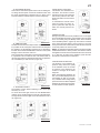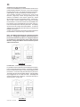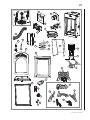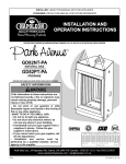
1
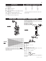
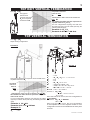
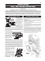
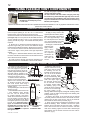
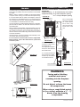
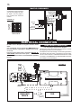
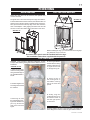
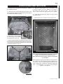
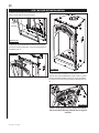
W415-0536 / C / 09.06.06
W415-0536 / C / 09.06.06
WARNINGS & SAFETY PRECAUTIONS
Do not store gasoline or other
flammable vapours and liquids in the
vicinity of this or any other appliance.
1.
2.
3.
Installation and service must be
performed by a qualified installer,
service agency or the gas supplier.
Follow the installation directions.
4.
5.
6.
WHAT TO DO IF YOU SMELL GAS
Do not try to light any appliance.
Do not use any phone in your building.
Immediately call your gas supplier
from a neighbor's phone. Follow the
gas supplier's instructions.
Do not touch any electrical switch.
If you cannot reach your gas supplier,
call the fire department.
If this fireplace is not properly
installed, a house fire may result.
W415-0536 / C / 09.06.06
TABLE of CONTENTS
PG2-6introduction
18
6-10
Warnings and Safety Precautions
Warranty
Dimensions
General Instructions
General Information
Care of Glass & Plated Parts
venting
Vent lengths
Venting Specifications
Air Terminal Locations
11-16
INSTALLATION/FRAMING
16
Door Removal
Log Shipping Bracket
Log Placement
Glowing Embers
19
DECORATIVE BRICK PANEL
INSTALLATION
20
AFK / WI FACE KIT
INSTALLATION
21
REMOTE AND VALVE ACCESS
27
ELECTRICAL CONNECTION
17finishing
Night Light Replacement
Burner Assembly Removal
22-27 OPERATION / MAINTENANCE
Fireplace Operation
Wall & Ceiling Protection
Using Flexible Vent Components
Fireplace Vent Connection
Using Rigid Vent Components
Gas Installation
Restricting Vertical Vents
Framing
Clearance to Combustibles
Mantle Clearances and Enclosures
Hard Wiring Connections
Schematic
Blower REPLACEMENT
Hand Held Remote Operation
Operating Instructions
adjustments
Pilot Burner Adjustment
Venturi Adjustment
28-29 REPLACEMENTS
Ordering Replacement Parts
Replacement Parts
Terminal Kits
Vent Kits
Accessories
20-31 Trouble Shooting Guide
PLEASE RETAIN THIS MANUAL for future reference
warning
• Do not burn wood or other materials in this fireplace.
• Adults and especially children should be alerted to the hazards of high surface temperatures and should stay away to
avoid burns or clothing ignition. Keep young children and animals away when the fireplace is hot.
• Due to high temperatures, the fireplace should be located out of traffic and away from furniture and draperies.
• Clothing or other flammable material should not be placed on or near the fireplace.
• Any safety screen or guard removed for servicing must be replaced prior to operating the fireplace.
• It is imperative that the control compartments, burners and circulating blower and its passageway in the fireplace and
venting system are kept clean. The fireplace and its venting system should be inspected before use and at least annually by a qualified service person. More frequent cleaning may be required due to excessive lint from carpeting, bedding
material, etc. The fireplace area must be kept clear and free from combustible materials, gasoline and other flammable
vapours and liquids.
• Under no circumstances should this fireplace be modified.
• This fireplace must not be connected to a chimney flue pipe serving a separate solid fuel burning appliance.
• Do not use this fireplace if any part has been under water. Immediately call a qualified service technician to inspect the
fireplace and to replace any part of the control system and any gas control which has been under water.
• Do not operate the fireplace with the glass door removed, cracked or broken. Replacement of the glass should be done
by a licensed or qualified service person.
• Do not strike or slam shut the fireplace glass door.
• This fireplace uses and requires a fast acting thermocouple. Replace only with a fast acting thermocouple supplied by
Wolf Steel Ltd.
note: Changes, other than editorial, are denoted by a vertical line in the margin.
W415-0536 / C / 09.06.06
napoleon products are manufactured under the strict Standard of the world recognized ISO 9001 : 2000 Quality Assurance Certificate.
napoleon products are designed with superior components and materials, assembled
by trained craftsmen who take great pride in their work. The burner and valve assembly are
leak and test-fired at a quality test station. The complete fireplace is thoroughly inspected
by a qualified technician before packaging to ensure that you, the customer, receives the
quality product that you expect from napoleon.
napoleon gas fireplace president’s lifetime limited warranty
The following materials and workmanship in your new napoleon gas fireplace are warranted against defects
for as long as you own the fireplace. This covers: combustion chamber, heat exchanger, stainless steel burner,
phazer™ logs and embers, ceramic glass (thermal breakage only), gold plated parts against tarnishing,
porcelainized enamelled components and aluminum extrusion trims.
Electrical (110V and millivolt) components and wearable parts such as the blower, gas valve, thermal switch,
switches, wiring, remote control, ignitor, gasketing, and pilot assembly are covered and napoleon will
provide replacement parts free of charge during the first year of the limited warranty. Light bulbs are not
covered by this warranty.
Labour related to warranty repair is covered free of charge during the first year. Repair work, however,
requires the prior approval of an authorized company official. Labour costs to the account of napoleon
are based on a predetermined rate schedule and any repair work must be done through an authorized
napoleon dealer.
conditions and limitations
napoleon warrants its products against manufacturing defects to the original purchaser only -- i.e., the individual or legal entity (registered customer)
whose name appears on the warranty registration card filed with napoleon -- provided that the purchase was made through an authorized napoleon
dealer and is subject to the following conditions and limitations:
This factory warranty is nontransferable and may not be extended whatsoever by any of our representatives.
The gas fireplace must be installed by a licenced, authorized service technician or contractor. Installation must be done in accordance with the installation
instructions included with the product and all local and national building and fire codes.
This limited warranty does not cover damages caused by misuse, lack of maintenance, accident, alterations, abuse or neglect and parts installed from other
manufacturers will nullify this warranty.
This limited warranty further does not cover any scratches, dents, corrosion or discolouring caused by excessive heat, abrasive and chemical cleaners nor chipping on porcelain enamel parts, mechanical breakage of phazer™ logs and embers, nor any venting components used in the installation of the fireplace.
Napoleon warrants its stainless steel burners against defects in workmanship and material for life, subject to the following conditions: During the first 10
years Napoleon will replace or repair the defective parts at our option free of charge. From 10 years to life, napoleon will provide replacement burners
at 50% of the current retail price.
In the first year only, this warranty extends to the repair or replacement of warranted parts which are defective in material or workmanship provided that the
product has been operated in accordance with the operation instructions and under normal conditions.
After the first year, with respect to this President’s Limited Lifetime Warranty, napoleon may, at its discretion, fully discharge all obligations with respect
to this warranty by refunding to the original warranted purchaser the wholesale price of any warranted but defective part(s).
After the first year, napoleon will not be responsible for installation, labour or any other costs or expenses related to the reinstallation of a warranted part,
and such expenses are not covered by this warranty.
Notwithstanding any provisions contained in this President’s Limited Lifetime Warranty, napoleon’s responsibility under this warranty is defined as above
and it shall not in any event extend to any incidental, consequential or indirect damages.
This warranty defines the obligations and liability of napoleon with respect to the napoleon gas fireplace and any other warranties expressed or implied
with respect to this product, its components or accessories are excluded.
napoleon neither assumes, nor authorizes any third party to assume, on its behalf, any other liabilities with respect to the sale of this product. napoleon
will not be responsible for: over-firing, downdrafts, spillage caused by environmental conditions such as rooftops, buildings, nearby trees, hills, mountains,
inadequate vents or ventilation, excessive venting configurations, insufficient makeup air, or negative air pressures which may or may not be caused by
mechanical systems such as exhaust fans, furnaces, clothes dryers, etc.
Any damages to fireplace, combustion chamber, heat exchanger, brass trim or other component due to water, weather damage, long periods of dampness,
condensation, damaging chemicals or cleaners will not be the responsibility of napoleon.
The bill of sale or copy will be required together with a serial number and a model number when making any warranty claims from your authorized dealer.
The warranty registration card must be returned within fourteen days to register the warranty.
napoleon reserves the right to have its representative inspect any product or part thereof prior to honouring any warranty claim.
All specifications and designs are subject to change without prior notice due to on-going product improvements. Napoleon® is a registered
trademark of wolf steel ltd. Patents u.s. 5.303.693.801 - can. 2.073.411, 2.082.915. © wolf steel ltd.
W415-0536 / C / 09.06.06
figure 1
58"
46"
37 5/8"
17 3/4"
4" DIA.
7" DIA.
5"
2"
24"
28"
/"
78
8 7/8"
General instructions
This gas fireplace should be installed and serviced by a qualified installer to conform with local
codes. Installation practices vary from region to region and it
is important to know the specifics that apply to your area,
for example: in Massachusetts State:
• The fireplace damper must be removed or welded in the open position prior to installation of a fireplace insert or gas log.
• A carbon monoxide detector is required in all rooms containing gas fired appliances.
• The appliance off valve must be a “T” handle gas cock.
• The flexible connector must not be longer than 36 inches.
• The appliance is not approved for installation in a bedroom or bathroom unless the unit is a direct vent sealed combustion product.
• WARNING: This product must be installed by a licensed plumber or gas fitter when installed within the commonwealth of Massachusetts.
In absence of local codes, install to the current CAN/CGA
-B149 Installation Code in Canada or to the National Fuel
Gas Code, ANSI Z223.1, and NFPA 54 in the United States.
Suitable for mobile home installation if installed in accordance
with the current standard CAN/CSA Z240MH Series, for gas
equipped mobile homes, in Canada or ANSI Z223.1 and NFPA
54 in the United States.
The fireplace and its individual shutoff valve must be disconnected from the gas supply piping system during any pressure
testing of that system at test pressures in excess of 1/2 psig
(3.5 kPa). The fireplace must be isolated from the gas supply
piping system by closing its individual manual shutoff valve
during any pressure testing of the gas supply piping system
at test pressures equal to or less than 1/2 psig (3.5 kPa).
When the fireplace is installed directly on carpeting, vinyl tile
or other combustible material other than wood flooring, the
fireplace shall be installed on a metal or wood panel extending
the full width and depth.
The optional heat circulating blower is supplied with a cord. If
installed, the junction box must be electrically connected and
grounded in accordance with local codes. In the absence of
local codes, use the current CSA C22.1 canadian electrical code in Canada or the ANSI/NFPA 70 national
electrical code in the United States.
Purge all gas lines with the glass door of the fireplace open.
Assure that a continuous gas flow is at the burner before
closing the door.
Under extreme vent configurations, allow several minutes
(5-15) for the flame to stabilize after ignition.
Provide adequate ventilation and combustion air.
Provide adequate accessibility clearance for servicing and
operating the fireplace. Never obstruct the front opening of
the fireplace.
13 / "
78
1
21" 22 /8"
14"
28"
Objects placed in front of the fireplace must be kept a
minimum of 48” from the front face of the unit.
Minimum clearance to combustible construction
from fireplace and vent surfaces:
fireplace framing - 0” to stand-offs (top, rear and sides)
fireplace finishing - 4” from the sides of firebox opening
21 3/4” to top of fireplace opening.
vent pipe
- 2 inches*
recessed depth
- 22 1/4 inches
* The first 2 feet of outer 7 inch diameter vent pipe from the appliance
must be wrapped in the 1” thick insulation sleeve (supplied).
General inFORMATION
FOR YOUR SATISFACTION, THIS FIREPLACE HAS BEEN
TEST-FIRED TO ASSURE ITS OPERATION AND QUALITY! There must be a 1” air gap in addition to the insulation
sleeve. Maximum input is 26,000 BTU/hr for both natural
gas and propane. When the fireplace is installed at elevations
above 4,500ft, and in the absense of specific recommendations from the local authority having jurisdiction, the certified
high altitude input rating shall be reduced at the rate of 4%
for each additional 1,000ft. Maximum output for natural gas
is 16,150 BTU/hr at an efficiency of 62%; and 16,150 BTU/hr
for propane at an efficiency of 62%. Minimum inlet gas supply
pressure is 4.5 inches water column for natural gas and 11
inches water column for propane. Maximum inlet gas pressure
is 7 inches water column for natural gas and 13 inches water
column for propane. Manifold pressure under flow conditions
is 3.5 inches water column for natural gas and 10 inches water
column for propane.
This fireplace is approved for bathroom, bedroom and bedsitting room installations and is suitable for mobile home
installation. The natural gas model can only be installed in
a mobile home that is permanently positioned on its site and
fueled with natural gas.
This fireplace may be installed in an aftermarket permanently
located, manufactured (mobile) home, where not prohibited
by local codes.
This fireplace is only for use with the type of gas indicated
on the rating plate. This fireplace is not convertible for use
with other gases, unless a certified kit is used.
No external
electricity
(110 volts or
24 volts) is required for the
gas system operation.
W415-0536 / C / 09.06.06
Care of glass, and plated parts
Expansion / contraction nosies during heating up and cooling down cycles are normal and are to be expected. Change in
flame appearance from “HI” to “LO” is more evident in natural gas than in propane.
Do not use abrasive cleaners to clean plated parts. Buff lightly with a clean dry cloth. The glass is 3/16” ceramic glass available from your Napoleon / Wolf Steel Ltd. dealer. do not substitute materials. Clean the glass after the first 10
hours of operation with a recommended gas fireplace glass cleaner. Thereafter clean as required. do not clean glass
when hot! If the glass is not kept clean permanent discolouration and / or blemishes may result.
vENTING
VENTING LENGTHS & air terminal
For safe and proper operation of the fireplace follow the
venting instruction exactly.
Deviation from the minimum vertical vent length can create
difficulty in burner start-up and/or carboning.
Provide a means for visually checking the vent connection to
the fireplace after the fireplace is installed.
Vent lengths that pass through unheated spaces (attics, garages, crawl spaces) should be insulated with the insulation
wrapped in a protective sleeve to minimize condensation.
Use only Wolf Steel, Simpson Dura-Vent, Selkirk Direct Temp
or American Metal Amerivent venting components.
Wolf Steel, Simpson Dura-Vent, Selkirk Direct Temp and
American Metal Amerivent venting systems must not be
combined.
Follow the installation procedure provided with the venting
components.
For vent systems that provide seals on the inner exhaust flue,
only the outer air intake joints must be sealed using a red high
temperature silicone (RTV). This same sealant maybe used
on both the inner exhaust and outer intake vent pipe joints
of all other approved vent systems except for the exhaust
vent pipe connection to the fireplace flue collar which must
be sealed using the black high temperature sealant Mill Pac.
A starter adaptor must be used and may be purchased from
the corresponding supplier:
Supplier
4/7
Duravent
W175-0053
Amerivent
4DSC-N2
Direct Temp
4DT-AAN
When using Napoleon venting components, use only approved Wolf Steel Ltd. rigid / flexible vent components with the
following termination kits: wall terminal kit gd222r, or
1/12 to 7/12 pitch roof terminal kit gd110, 8/12 to
12/12 roof terminal kit gd111, flat roof terminal
kit gd112 or periscope kit GD201 (for wall penetration
below grade). With flexible venting, in conjunction with the
various terminations, use either the 5 foot vent kit gd220 or
the 10 foot vent kit gd330. These vent kits allow for either
horizontal or vertical venting of the fireplace.
The maximum allowable vertical vent length is 40 feet
using flexible venting. The maximum number of allowable 4”
vent connections is three horizontally or vertically (excluding the fireplace and the air terminal connections).
For optimum flame appearance and fireplace performance,
keep the vent length and number of elbows to a minimum.
W415-0536 / C / 09.06.06
The air terminal must remain unobstructed at all times. Examine the air terminal at least once a year to verify that it is
unobstructed and undamaged.
Horizontal runs may have a 0 inch rise per foot in all
cases using simpson dura-vent or napoleon rigid
or flexible venting components when venting as illustrated in Figures 2a, 2b, and 2c.
When venting, the horizontal run must be kept to a
minimum of 16 inches or a maximum of 20 feet. If a 20
foot horizontal run is required, the fireplace must have
a minimum vertical rise immediately off the fireplace of
57 inches. figures 2a-c. When terminating vertically,
the vertical rise is a minimum 34 inches and a maximum
40 feet above the fireplace. figure 3.
figures 2a-c
16"
24"
8"
figure 3
For optimum performance, it is recommended that all
horizontal runs have a minimum ¼ inch rise per foot.
Provide a means for visually checking the vent connection to the fireplace after the fireplace is installed.
Do not allow the inside liner to bunch up on horizontal
or vertical runs and elbows. Keep it pulled tight. A 1¼”
air gap between the inner and outer liner all around is
required for safe operation.
Vent lengths that pass through unheated spaces (attics,
garages, crawl space) should be wrapped with a protective insulation sleeve to minimize condensation.
Use a firestop when penetrating interior walls, floor or
ceiling.
For safe and proper operation of the fireplace follow the
venting instruction exactly.
Deviation from the minimum vertical vent length can create difficulty in burner start-up and/or carboning.
DEFINITIONS
for the following symbols used in the venting calculations
and examples are:
> - greater than
> - equal to or greater than
< - less than
< - equal to or less than
Ht- total of both horizontal vent lengths (Hr) and offsets (Ho) in feet
Hr- combined horizontal vent lengths in feet
Ho- offset factor: .03(total degrees of offset - 90°*) in feet
Vt- combined vertical vent lengths in feet
ELBOW VENT LENGTH VALUES
feet
inches
1°
0.03
0.5
15°
0.45
6.0
30°
0.911.0
45°1.3516.0
90°* 2.7
32.0
* the first 90° offset has a zero value and is shown in the formula as -90°
TOP EXIT / horizontal termination
See graph to determine the required vertical rise VT for the
required horizontal run HT.
For vent configurations requiring more than one 90° elbow,
the following formulas apply:
Formula 1: HT < VT
Formula 2: HT + VT < 40 feet
H2
90°
figure 4
V2
figure 5
90°
when (Ht) < (Vt)
Simple venting configuration (only one 90° elbow)
vertical
rise in
feet
VT
horizontal vent run PLUS OFFSET in feet HT
The shaded area within the lines represents acceptable
values for HT and VT .
90°
V1
H1
Example 1:
V1 = 3 ft
V2 = 8 ft
VT = V1 + V2 = 3 + 8 = 11 ft
H1 =2.5 ft
H2 =2 ft
HR = H1 + H2 = 2.5 + 2 = 4.5 ft
HO = .03(three 90° elbows - 90°) = .03(270° - 90°) = 5.4 ft
HT = HR + HO = 4.5 + 5.4 = 9.9 ft
HT + VT = 9.9 + 11 = 20.9 ft
Formula 1: HT < VT
9.9 < 11
Formula 2: HT + VT < 40 feet
20.9 < 40
Since both formulas are met, this vent configuration is
acceptable.
W415-0536 / C / 09.06.06
TOP EXIT / horizontal termination
V1
= VT = 6 ft
H1
= 3 ft
H2
= 5 ft
HR
= H1 + H2 = 3 + 5 = 8 ft
H O
= .03(two 90° elbows - 90°) = .03(180° - 90°) = 2.7 ft
HT = HR + HO = 8 + 2.7 = 10.7 ft
HT + VT= 10.7 + 6 =16.7
Formula 1: HT < 4.2 VT
4.2 VT = 4.2 x 6 = 25.2 ft
when (Ht) > (Vt)
Simple venting configuration (only one 90° elbow)
figure 6
See graph to determine the required vertical rise Vt for the required horizontal run
Ht.
10.7 < 25.2
Formula 2: HT + VT < 24.75 feet
16.7 < 24.75
Since both formulas are met, this vent configuration is acceptable.
Example 3:
required
vertical
rise in
inches
90°
H1
VT
V1
90°
H2
V2
H4
H3
figure 8
V1
=4 ft
horizontal vent run PLUS OFFSET in feet HT
=1.5 ft
The shaded area within the lines represents acceptable V2
VT
= V1 + V2 = 4 + 1.5 = 5.5 ft
values for HT and VT .
H1
=2 ft
For vent configurations requiring more than one 90° elbow the
H2
=1 ft
following formulas apply:
H3
=1 ft
Formula 1: HT < 4.2 VT
H4
=1.5 ft
Formula 2: HT + VT < 24.75 feet
HR
= H1 + H2 + H3 + H4 = 2 + 1 + 1 + 1. 5 = 5.5 ft
HO
= .03(four 90° elbows - 90°) = .03(360° - 90°) = 8.1 ft
HT =HR + HO = 5.5 + 8.1 = 13.6 ft
Example 2:
H1
HT + VT = 13.6 + 5.5 = 19.1 ft
H2
V1
90°
Formula 1: HT < 4.2 VT
4.2 VT = 4.2 x 5.5 = 23.1 ft
13.6 < 23.1
Formula 2: HT + VT < 24.75 feet
figure 7
19.1 < 24.75
Since both formulas are met, this vent configuration is
acceptable.
W415-0536 / C / 09.06.06
TOP EXIT VERTICAL termination
when (Ht) < (Vt)
See graph to
determine the
required vertical rise
VT for the required
horizontal run HT.
required vertical
rise in feet
VT
horizontal vent run PLUS OFFSET in
feet HT
The shaded area within the lines represents acceptable values for HT and VT .
For vent configurations requiring more than zero
90° elbow (top exit) or one 90° elbow (rear exit), the
following formulas apply:
Formula 1: HT < VT
Formula 2: HT + VT < 40 feet
figure 9
TOP VERTICAL termination
when (Ht) > (Vt)
Simple venting configurations
figure 10
90°
V1
90°
H1
H2
V2
90°
V3
90°
figure 11
See graph to determine the required vertical rise VT for the
required horizontal run HT.
maximum
vertical
rise in
feet
VT
horizontal vent run PLUS OFFSET in feet HT
The shaded area within the lines represents acceptable
values for HT and VT .
For vent configurations requiring more than two 90° elbow
(top exit) or one 90° elbow (rear exit), the following formulas
apply:
Formula 1: HT < 3VT
Formula 2: HT + VT < 40 feet
Example 7:
V1
V2
=2 ft
=1 ft
V3
VT
H1
H2
HR
HO
HT HT + V T
=1.5 ft
=V1 + V2 + V3 = 2 + 1 + 1.5 = 4.5 ft
=6 ft
=2 ft
=H1 + H2 = 6 + 2 = 8 ft
=.03(four 90° elbows - 90°)
=.03(90 + 90 + 90 + 90 - 90) = 8.1 ft
=HR + HO = 8 + 8.1 = 16.1 ft
= 16.1 + 4.5 = 20.6 ft
Formula 1: HT < 3VT
3VT = 3 x 4.5 = 13.5 ft
16.1
>
13.5
Since this formula is not met, this vent configuration is
unacceptable.
Formula 2: HT + VT < 40 feet
20.6 < 40
Since only formula 2 is met, this vent configuration
is unacceptable and a new fireplace location or vent
configuration will need to be established to satisfy both
formulas.
W415-0536 / C / 09.06.06
10
figure 12
W415-0536 / C / 09.06.06
11
INSTALLATION
WALL AND CEILING PROTECTION
For optimum performance it is recommended that all horizontal runs have a minimum ¼ inch rise per foot using
flexible venting.
For safe and proper operation of the fireplace, follow the venting instructions exactly.
Horizontal Termination: A clearance to combustibles of 2" must be maintained during the first 24” of venting when pentrating combustible walls. The firestop spacer (W500-0292) supplied with the unit should be used to
maintain this clearance. The first two feet of outer 7” diameter vent pipe, from the appliance must be wrapped in
the 1 inch thick insulation sleeve (supplied) as well as having a 1 inch air gap. Thereafter a 1” clearance to combustibles may be maintained using firestop spacer (W615-0044 for use with flexible venting or rigid venting.)
VERTICAL INSTALLATION
HORIZONTAL INSTALLATION
This application occurs
when venting through
a roof. Installation kits
figure 13
for various roof pitches
are available from your
Napoleon dealer. See
11
11
Accessories to order the
specific kit required.
1. Determine the air
terminal location, cut
and frame 9½ or 11½
inch openings in the ceiling and the roof to provide the minimum clearance between
the fireplace pipe / liner and any combustible material. Try to
center the exhaust pipe location midway between two joist to
prevent having to cut them. Use a plumb bob to line up the
center of the openings.
do not fill this space with any type of material.
A vent pipe shield will
prevent any materials such as insulation,
from filling up the 1" air figure 14
space around the pipe.
Nail headers between
the joist for extra support.
2. Apply a bead of
caulking (not supplied) to the framework or to the Wolf Steel
vent pipe shield plate or equivalent (in the case of a finished
ceiling), and secure over the opening in the ceiling. A firestop
must be placed on the bottom of each framed opening in a
roof or ceiling that the venting system passes through. Apply
a bead of caulking all around and place a firestop spacer over
the vent shield to restrict cold air from being drawn into the
room or around the fireplace. Ensure that both spacer and
shield maintain the required clearance to combustibles. Once
the vent pipe / liner is installed
in its final position, apply sealant
VENT
between the pipe / liner and the
PIPE
firestop spacer.
COLLAR
3. In the attic, after the pipe /
liner has been installed, slide the
VENT PIPE
vent pipe collar down to cover up
SHIELD
the open end of the shield and
tighten. This will prevent any
materials, such as insulation,
FIGURE 15
from filling up the 1" air space
around the pipe.
This application occurs when venting through an exterior
wall. Having determined the air terminal location, cut and
frame a hole in an exterior wall with a minimum rectangle
opening of 12” x 11”.
IMPORTANT: For optimum performance, The stove pipe
should rise ¼” per foot of run.
1. Assemble the shield to the spacer as shown, using the
3 shorter screws supplied.
The shield is meant to protect combustible materials within
the wall. If the shield is deeper than the combustible portion
of the wall, cut to fit.
2. Apply a bead of caulking all around and place the firestop
spacer over the framework to restrict cold air from being drawn
into the room or around the stove. Ensure that both spacer
and shield maintain the required clearance to combustibles.
Secure the spacer in place using the 4 longer screws supplied. Once the vent pipe is installed in its final position, apply
sealant between the pipe and the firestop spacer.
W415-0536 / C / 09.06.06
12
USING FLEXIBLE VENT COMPONENTS
Use only approved aluminum flexible liner kits
marked:
“Wolf Steel Approved Venting” as
identified by the stamp only on the
7” outer liner.
For safe and proper operation of the fireplace, follow the
venting instructions exactly.
All inner exhaust and outer intake vent pipe joists may
be sealed using either Red RTV high temp silicone sealant or Black high temp Mill Pac with the exception of the
fireplace exhaust flue collar which must be sealed using
Mill Pac (not supplied).
Spacers are attached to the inner flex liner at predetermined intervals to maintain a 1-1/4” air gap to the outer flex liner. These
spacers must not be removed.
HORIZONTAL AIR TERMINAL INSTALLATION
1. Cut or frame a hole in an exterior wall with a minimum
round or square opening of 111/2” W x 111/2” H. Secure the
firestop spacer over the opening to the interior wall.
Secure the terminal to the terminal extension plate if required
(see figure 18). The cover plate of the GD-222R terminal is
13”x13” and will cover the 11 1/2” x 11 1/2” opening but if the
opening is made any larger - the terminal extension plate is
required.
2. Stretch the 4” diameter aluminum flexible liner to the
required length taking into account the additional length
needed for the finished wall surface. Slip the liner a minimum
of 2” over the inner sleeve of the air terminal and secure with
3 #8 screws. Apply a heavy bead of the high temperature
sealant.
3. Using the 7” diameter flexible aluminum liner, slide over
the outer combustion air sleeve of the air terminal and secure
with 3 #8 screws. Seal as before.
4. Insert the liners through the firestop maintaining the
required clearance to combustibles. Secure to the exterior
wall and make weather tight by
5. Apply a heavy bead of the
high temperature sealant, (W5730007 not provided), to the inside of
the 4” liner approximately 1” from
the end. Slip the liner a minimum
of 2” over the fireplace vent collar
and secure with 3 #8 screws. figure 17
6. Using the 7” diameter flexible
aluminium liner,
apply sealant,
slide a mini7
4
mum of 2” over
the fireplace
combustion air
7
collar and secure with 3 #8
FIGURE 18
screws.
CAULKING
#10x2"
SCREWS
CAULKING
4"FLEX
PIPE
7" FLEX PIPE
2" OVERLAP
TERMINAL
EXTENSION
PLATE
HI-TEMP
SEALANT
VERTICAL AIR TERMINAL INSTALLATION
1. Fasten the roof support to the a
roof using the screws provided.
The roof support is optional. In
this case the venting is to be adequately supported using either an
alternate method suitable to the
authority having jurisdiction or the
optional roof support. (Fig.a)
ROOF SUPPORT
2. Stretch the inner aluminum
flex liner to the required length. FIGURE 19a,b&c
Slip the liner a minimum of 2” over the inner sleeve of the
air terminal connector and secure
with 3 #8 screws. Seal using a
INNER
SLEEVE
heavy bead of the high temperature
sealant. (Fig.b)
3. Repeat using the outer aluminum
flex liner. (Fig.b)
b
AIR
4. Thread the air terminal connector TERMINAL
/ liner assembly down through CONNECTOR
the roof. The air terminal must
be located vertically and plumb.
HIGH
Attach the air terminal connector to
TEMPERATURE
the roof support, ensuring that the
SEALANT
top of the air terminal is 16” above
INNER FLEX
LINER
the highest point that it penetrates
OUTER FLEX
the roof. (Fig.c) If the attic space is
LINER
tight, we recommend threading
the Wolf Steel vent pipe collar or Do not clamp the
flexible
equivalent loosely onto the air
terminal assembly as it is passed aluminium liner.
through the attic.
W415-0536 / C / 09.06.06
5. Remove nails from the c
shingles, above and to the
sides of the chimney. Place
the flashing over the air
terminal connector leaving a
2”
AIR INLET
min. 3/4” of the air terminal
BASE
connector showing above
the top of the flashing. Slide
CAULKING
the flashing underneath the
STORM COLLAR
sides and upper edge of
the shingles. Ensure that
the air terminal connector
WEATHER
SEALANT
is properly centred within
the flashing, giving a 3/4”
margin all around. Fasten to
FLASHING
the roof. Do not nail through
the lower portion of the
flashing. Make weather-tight by sealing with caulking. Where
possible, cover the sides and top edges of the flashing with
roofing material. (Fig.c)
6. Aligning the seams of the terminal and air terminal
connector, place the terminal over the air terminal connector
making sure the liner goes into the hole in the terminal.
Secure with the three screws provided. (Fig.c)
7. Apply a heavy bead of weatherproof caulking 2 inches
above the flashing. Note: Maintain a minimum 2” space
between the air inlet base and the storm collar. Install the
storm collar around the air terminal connector and slide
down to the caulking. Tighten to ensure that a weather-tight
seal between the air terminal connector and the collar is
achieved. (Fig.c)
SEALANT
13
FIREPLACE VENT CONNECTION
1. Install the 4” diameter aluminium flexible liner to the
fireplace. Secure with 3 screws and flat washers. Seal the
joint and screw holes using the high temperature sealant
(W573-0007 not provided).
2. Install the 7” diameter aluminium flexible liner to the
fireplace. Attach and seal the joints.
figure 20
USING RIGID VENT COMPONENTS
The vent system must be supported approximately every 3
feet for both vertical and horizontal runs. Use Wolf Steel vent
spacers or equivalent every 3 feet and either side of each
elbow to maintain the minimum 1¼” clearance between the
outer and inner vent pipes. Use Wolf Steel support ring assembly or equivalent noncombustible strapping to maintain
the minimum clearance to combustibles for both vertical and
horizontal runs.
All inner exhaust and outer intake vent pipe joists
may be sealed using either Red RTV high temp
silicone sealant or Black high temp Mill Pac with
the exception of the fireplace exhaust flue collar
which must be sealed using Mill Pac (not supplied).
HORIZONTAL AIR TERMINAL INSTALLATION
FIGURE 21
1. Move the fireCAULKING
place into position.
#10x2½"
Measure the vent
SCREWS
CAULKING
length required
7" PIPE
4" PIPE
between terminal
and fireplace tak2" OVERLAP
ing into account
MP
HI-TE T
N
SEALA
the additional
HI-TEMP
length needed for
SEALANT
the finished wall
surface and any
1¼” overlaps between venting components.
2. Apply high temperature sealant (W573-0007 not provided) to the outer edge of the 4” inner collar of the fireplace. Attach the first vent component and secure using 3 self
tapping screws. Repeat using 7” piping.
3. Holding the air terminal (with the air deflectors to the
top and the lettering in an upright, readable position) insert
the terminal into both vent pipes with a twisting motion to
ensure that both the terminal sleeves engage into the vent
pipes and sealant. Secure the terminal to the exterior wall and
make weather tight by sealing with caulking (not supplied).
EXTENDED HORIZONTAL AIR TERMINAL
INSTALLATION
1. Follow the instructions
figure 22
for “Horizontal Air Terminal AIR TERMINAL
Installations”, items 1 to 3.
TELESCOPIC SLEEVE
2. Continue adding components alternating inner
20"
and outer venting. Ensure COUPLER
that all 4” venting and elbows
VENTING
have sufficient vent spacers
attached and each component is securely fastened to
the one prior. Attach the 4”
telescopic sleeve to the vent
run.
Repeat using a 7” telescopic sleeve. Secure and seal as
before. To facilitate completion, attach 4” and 7” couplers to
the air terminal.
3. Install the air terminal. See item 3 of the Horizontal Air
Terminal Installation. Extend the 4” telescopic sleeve; connect to the air terminal assembly. Fasten with self tapping
screws and seal. Repeat using the 7” telescopic sleeve.
W415-0536 / C / 09.06.06
14
VERTICAL VENTING INSTALLATION
GAS INSTALLATION
1. Move the fireplace into position.
2. Fasten the roof support to the roof using the screws
provided. The roof support is optional. In this case the venting is to be adequately supported using either an alternate
method suitable to the authority having jurisdiction or the
optional roof support.
3. Apply high temperature sealant to the outer edge of the inner
sleeve of the air terminal. Slip a 4”
diameter coupler a minimum of 2”
over the sleeve and secure using
3 screws.
4. Apply high temperature sealant to the outer edge of the of the
outside sleeve of the air terminal.
Slip a 7” diameter coupler over
58"
the sleeve and secure as before.
46"
Trim the 7” coupler even with the
FIGURE 23
33 5/8"
4” coupler end.
Proceed once the vent installation is complete.
Note : All gas connections must be contained within
the fireplace when complete.
1. The fireplace is designed to accept a ½” gas supply line.
The fireplace is equipped with a ½” manual shut-off valve, and
an 18” listed flexible gas connector.
FIGURE 25
AIR INLET
BASE
2”
2. The access to the gas inlet is
located on the right side of the outer
shell.
CAULKING
STORM COLLAR
WEATHER
SEALANT
3. The flex connector and shut off
must all be within the outer shell.
FLASHING
5. Thread the air terminal pipe
VENT
assembly down through the roof
PIPE
support and attach, ensuring that
COLLAR
a minimum 16” of air terminal will
VENT PIPE
penetrate the roof when fastened.
SHIELD
The air terminal must be located
vertically and plumb.
28"
6. Remove nails from the shingles, above and to the sides of
FIGURE 24
the chimney. Place the flashing
over the air terminal and slide it
underneath the sides and upper edge of the shingles. Ensure
that the air terminal is properly centred within the flashing, giving a 3/4” margin all around. Fasten to the roof. Do NOT nail
through the lower portion of the flashing. Make weather-tight
by sealing with caulking. Where possible, cover the sides and
top edges of the flashing with roofing material.
7. Apply a heavy bead of waterproof caulking 2 inches
above the flashing. Slide the storm collar around the air terminal connector and down to the caulking. Tighten to ensure
that a weather-tight seal between the air terminal and the
collar is achieved.
8. Continue adding rigid venting sections, sealing and
securing as above. Attach a 4” collapsed telescopic pipe to
the last section of rigid piping. Secure with screws and seal.
Repeat using a 7” telescopic pipe.
9. Run a bead of high temperature sealant around the
outside of the 4” collar on the fireplace. Pull the adjustable
pipe a minimum of 2” onto the collar. Secure with 3 screws.
Repeat with the 7” telescopic pipe.
10. In the attic, slide the vent pipe collar down to cover up
the open end of the shield and tighten. This will prevent any
materials, such as insulation, from filling up the 1” air space
around the pipe.
W415-0536 / C / 09.06.06
/4" gas line, sup4. When flexing 17
any
DIA. gas valve so that the lines
port4"the
are
not bent.
7" DIA.
3
2"
8 7/8"
FIGURE 26
1
21" 22 /8"
5. Check for gas leaks by brushing
7
13 /8"
7
"
on a soap and/8water
solution. Do not
use open flame.
14"
28"
RESTRICTING VERTICAL VENTS
FIGURE 27
top of the
firebox
restrictor plate
FLUE COLLAR
Vertical terminations may display a very active flame. If this
appearance is not desirable, the vent exit must be restricted
using restrictor plate, W500-0205. This reduces the velocity
of the exhaust gases, slowing down the flame pattern and
creating a more traditional appearance.
The plate has a series of holes to allow for adjustment.
Remove the two screws on either side of the exhaust collar
inside the firebox. Install the plate in the desired set of holes,
then replace the screws.
It is recommend to secure in the third set of holes which
causes the greatest amount of restriction for vent length
between 15 and 30 feet.
15
CLEARANCE TO COMBUSTIBLES
FRAMING
It is best to frame your fireplace after it is positioned and the
vent system is installed. Use 2x4’s and frame to local building codes.
Note: In order to avoid the possibility of exposed insulation
or vapour barrier coming in contact with the fireplace body,
it is recommended that the walls of the fireplace enclosure
be “finished” (ie: drywall/sheetrock), as you would finish any
other outside wall of a home. This will ensure that clearance
to combustibles is maintained within the cavity.
It is not necessary to install a hearth extension, but the fireplace should be raised to be flush with either the hearth or
the finished floor.
When roughing in the fireplace, raise the fireplace to accommodate for the thickness of the finished floor materials, i.e.
tile, carpeting, hard wood, which if not planned for will interfere
with the removal of the hearth strip, which must be removed
to access the firebox.
Objects placed in front of the fireplace should be kept a minimum of 48” away from the front face.
For convenience, the stand-offs have been shipped flat.
Before framing, ensure the stand-offs are opened and
screwed in place.
MAINTAIN THESE MINIMUM CLEARANCES TO COMBUSTIBLES:
Fireplace framing - 0” to stand-offs (top, rear & sides)
Fireplace finishing - 4” to sides of fireplace opening.
- 21 3/4” to top of fireplace opening.
FIGURE 30
NON-COMBUSTIBLE
FINISHING MATERIAL
21 3/4"
59 3/8"
4"
4"
24"
32"
IMPORTANT:
The Park Ave. requires
a minimum inside enclosure height of 72”.
For temperature requirements, this area must be
left unobstructed.
1"
MIN
44"
1"
MIN
FIGURE 28
"
2 9 1 /8"
62
Non-combustible
finishing material
(ie: cement board,
brick, stone, tile)
may be used to finish the front of the
unit.
It is recommended that
the enclosure be ventilated at the top and bottom
to circulate the hot air.
COMBUSTIBLE
MATERIAL
FIRESTOP
SPACER
STUD
2"
2"
STAND OFF
SPACER
FIGURE 31
NON-COMBUSTIBLE
72"
opening.
29"
1/2"
FIGURE 29
22 1/2"
29"
WARNING
Facing and/or finishing
material must never
overhang into the fireplace
58 1/2"
22
72"
10"
MIN
2 FT.
MIN
Do not distort or force the frame
kit components.
When using a rough finish material (i.e.; stone), maintain a ¼” - ½”
border from the framing
components.
W415-0536 / C / 09.06.06
16
MANTLE CLEARANCES
Combustible mantle clearance
can vary according to the mantle depth. Use the graph to
help evaluate the clearance
needed.
FIRESTOP
SPACER
2"
STUD 1" GAP FROM INSULATION SLEEVE
2" GAP FROM VENTING
6"
figure 32
MH
AE
N I
TG
LH
ET
13
12
11
10
9
8
7
0
INSULATION
SLEEVE
5"
TOP OF
UNIT
TOP OF
FIREPLACE
OPENING
4"
3"
11"
12"
2"
2"
STAND OFF
SPACER
9"
10"
8"
1 2 3 4 5 6 7
MANTLE WIDTH
ELECTRICAL CONNECTION
Do NOT use the fireplace if any part has been under
water.
Call a qualified service technician IMMEDIATELY to
have the fireplace inspected for damage to the electrical circuit.
If access to the control area is necessary before installation, remove the access panel.
The access panel must be re-installed before operating
the unit.
HARD WIRING CONNECTION
It is necessary to hard wire this fireplace.
Permanently framing the fireplace with an enclosure, requires
the fireplace junction box to be hardwired.
This fireplace must be electrically connected and grounded in
accordance with local codes. In the absence of local codes,
use the current CSA C22.1 canadian electrical code
in Canada or the ANSI/NFPA 70-1996 national electrical code in the United States.
Schematic
figure 33
TH
TP
PILOT
MOTOR AUTO MAN
LINE
GAS
VALVE
ON
FAN
O FF
IN
OUT
AUX
AUXILIARY
DEVICE
W415-0536 / C / 09.06.06
L2
L1
[HOT]
FAN
17
FINISHING
Log SHIPPING BRACKET
door REMOVAL
Before the glass door can be removed, the optional front
must be removed.
The glass door is secured to the top front edge of the firebox.
Pull the handles of the latches forward, then lift the hooks out
from the slots in the door frame to release the top of the door.
Next, pivot forward until the top edge of the door clears the
front of the fireplace. Next gripping the sides of the door lift
the door out from the retainer along the bottom of the door.
figure 35
figure 34
Latches
LOG SHIPPING BRACKET
Before installing the logs, you must first remove the log shipping brackets. Lift up to remove.
Glass Door
Optional Front
Retainer
Decorative brick panels must be installed before the logs.
See installation instructions supplied with the panel kit.
Log Placement
tm
phazer logs, exclusive to Napoleon Fireplaces, provide
a unique and realistic glowing effect that is different in every
installation.
figure 36 a-F
1
1. Place the rear log #1
onto the locating studs
along the back edge of
the PHAZERAMIC™
burner.
4. Place log #4 with the
charred branch facing
inward. Position the pin
in log #4 into the hole
on the right of log #2.
5. Place log #5 so
the locating hole on
the botttom of the log
sits on the screw and
spacer.
2. Position log #2 in the
2 locating holes behind
the andirons.
4
5
2
3. Place log #3, with
the charred branch facing inward. Position the
pin in log #3 into the
hole on the left of the
log #2.
3
6. Finally, align the
rectangular peg on log
#6 with the notch on
the front right portion
of the burner.
6
GLOWING EMBERS
Glowing embers are NOT recommended. The burner has
been designed to achieve maximum glow without embers.
W415-0536 / C / 09.06.06
18
BLOWER REPLACEMENT
The Napoleon PARK AVENUE comes equipped with a heat
circulating blower. The blower is pre-wired and is controlled by
the remote control supplied with the unit. For control details,
see operation. Pg. 22.
Drywall dust will penetrate into the blower bearings, causing irreparable damage. Care must be taken to prevent
drywall dust from coming into contact with the blower or
its compartment. Any damage resulting from this condition is not covered by the warranty policy.
1. Turn off the power to the fireplace.
2. Turn off the gas valve.
3. Remove the glass door, logs, rear log supports, brick
panels, air deflector, burner assy, panel support, panel support bracket.
4. The blower mounting plate can now be removed. Remove
the four screws that secure the plate to the firebox base.
5. The blower is secured to the firebox. Disconnect the wire
connectors before attempting to remove the blower from the
firebox.
6. Remove the two screws securing the blower and lift through
blower access opening.
figure 37
figure 38
Note: When re-installing the replacement blower, it will be necessary to
replace the gasket (W290-0104) on
the blower mounting plate.
BLOWER
MOUNTING
PLATE
REMOVE 4 SCREWS
REMOVE 2 SCREWS
NIGHT LIGHT REPLACEMENT
Your PARK AVENUE comes equipped with our “Night Light”.
The light has been pre-wired and is controlled from the
remote control.
figure 41
If in the event the lamp or lens needs to be replaced, follow
the instructions below.
GASKET
AMBER
Unplug the wireharness
/ transformer from the
junction box inside the
fireplace.
SIDE UP
LENSE
FRAME
Remove the four screws that secure the lens frame.
This frame retains the glass lens. The lamp can now be
accessed.
figure 39
Note: Do not handle the lamp (bulb) with bare fingers,
protect with a clean dry cloth.
The lamp will pull straight out of the socket. Replace with
Wolf Steel parts only, as lamp and lens are special “high
temperature” products.
When re-installing, ensure integrity of gasket seal.
LENSE FRAME
SCREWS
The firebox must be sealed.
FIREBOX TOP
figure 40
W415-0536 / C / 09.06.06
Over tightening the screws could break the lens.
“Light Leakage” from the upper area may be observed.
The holes in the lamp housing are necessary for
ventilation and must not be covered.
19
DECORATIVE BRICK PANEL INSTALLATION
1. Carefully remove the glass door and all logs. (Refer to
the installation manual)
2. Remove the two screws holding the front portion of the
rear air deflector. Remove the pilot shield by removing the
two screws as illustrated. (Fig. 42)
5. Rest the bottom edge of the rear panel on top
of the rear portion of the air deflector at the back of
the firebox and push into place. The rear panel is
held in place when both side panels are in position.
6. Install the left brick panel using the same method
described in step 4.
figure 42
7. Replace the burner, air deflector, logs and glass door.
STEP
#2
1
2
3
PILOT SHIELD
3. Remove the 3 screws holding
the burner down and carefully
remove the burner. (Fig. 43)
4. Install the right brick panel by sliding the bottom edge of
the panel down the right firebox side then pivot the top edge
of the panel into place against the firebox wall. Hold in place
with the brick retainers. (Fig. 44)
figure 45
STEP
#3
HERRINGBONE PATTERN ILLUSTRATED
figure 43
Note: Due to the brittle material of the bricks, care must
be taken not to bend or force them into place.
Note: Refractory panels require a 24 hour curing period
on a low flame.
When shipped, the brick panels range in varying shades of
tan. During initial use, the panels will emit a slight odor for
a few hours. This is a normal condition that will not occur
again. Simply open a window to sufficiently ventilate the
room. The appearance of the panels will permanently
lighten in colour with use.
figure 44
W415-0536 / C / 09.06.06
20
afk / wi face kit installation
1. Attach screw and spacer as illustrated in Fig. 46 to the
bottom of both sides of the front housing.
SCREW
&
SPACER
figure 46
2. Attach the face plate bracket provided to the top edge
of the front housing using 2 #8 - 1/2” truss head screws as
illustrated in Fig. 47.
figure 47
figure 48
3. Lift and hook the faceplate over the spacers. Then
push the top of the faceplate back until it comes in contact
with the face plate bracket, then secure on the underside
by using the 2 1/4-20 screws provided as illustrated in Fig.
49.
figure 49
NOTE: A 1/4” gap must be maintained between
the front and all finishing material due to regular
removal.
W415-0536 / C / 09.06.06
21
REMOTE, Receiver AND VALVE ACCESS
Burner assembly removal
1a. Rectangular Front Removal
Pull on the top of the optional front away from the fireplace until
the male portion of the latch disengages. Tilt forward slightly
and lift from the 2 shoulder screws near the bottom.
1b. Heritage and Wrought Iron Front Removal
Remove the two screws in the slots located behind the inner
arch. (Fig. 50) Tilt forward slightly and lift from the 2 shoulder
screws near the bottom front. Note: Fronts are heavy so
when the second screw is removed the front will want
to fall forward.
2. Control Panel Removal
Lift the panel from the slots. This will allow access and removal
of the remote receiver and spark module.
If valve replacement is necessary following steps 1 and 2
above then proceed with the following ...
figure 50
AIR
DEFLECTOR
3. Door Removal
The glass door is secured at the top front edge of the fireplace.
Pull the latch forward then lift hook out from slot in the door.
Pivot door forward then lift out from retainer along the bottom
edge of the firebox.
4. Burner Removal
The phasoramic burner must be removed next. Remove the
2 screws holding the air deflector (Fig. 51). Then remove
the 3 screws holding the burner - 2 at the back and 1 at the
front (Fig. 52).
figure 51
Lift the burner out from the firebox.
5. Next, remove the 5 screws that secure the burner base.
Once the gas has been disconnected, the burner train assembly will lift out.
BURNER
figure 52
W415-0536 / C / 09.06.06
22
OPERATION / MAINTENANCE
TIME OUT
If the appliance is turned on and the Receiver does not receive
any command for 3 hours, it automatically turns the appliance
and the Remote Control off.
desired flame height. Six flame levels are included, from 1
(minimum) to 6 (maximum). An acoustic signal from the
Receiver confirms the reception of the command.
FIREPLACE OPERATION
To operate this firplace using the remote, the pilot must be
running and the gas valve turned to the “ON” position. Ensure
that the receiver has power and the backup switch is in the
auto position.
figure 54
figure 53
1. Install the batteries (AAA) into the remote control
transmitter. The “HOUSE” icon with room temperature will
be displayed.
2. Press the ON/OFF button on the remote. Icons
will appear at the same time and acoustic signal is
generated if not, move the transmitter closer to the receiver and repeat. If a signal is still not heard, it will be
necessary to execute the address setting procedure.
Note: There maybe a few seconds delay before the receiver
responds. Especially when using the wrought iron faceplate.
3. Fahrenheit - Celsius temperature indicatior
It is possible to set the Remote Control transmitter to display
the temperatures in either Fahrenheit or Celsius. Use the UP
or DOWN button on the transmitter until the cursor (small
triangle) is left of the clock icon.
4. From time 0:00 press the LEFT key ten times. The display
will show the transmitter address. Use the RIGHT button to
toggle from °F to °C and vice versa. The display will show
the selected unit of measue. Press the LEFT button to exit
this function.
HAND HELD REMOTE OPERATIONS
1. ON / OFF
To turn the fireplace on press the ON / OFF button, the
fireplace will always light at maximum flame setting. Press
the ON / OFF button again to turn the fireplace off.
3. AUTOMATIC CHANGE OF FLAME HEIGHT
The system is provided with three automatic sequences to
change continuously the flame height. Thirty steps compose
each sequence with an interval between one step and the
other of 5 seconds, for a total duration of 2.5 minutes. At the
end the sequence repeats continually until the sequence function is changed to an alternatate pattern or turned to off.
The Remote Control can select one of the predefinded sequences. Use the UP or Down button until the cursor (small
triangle) is to the left of the two small flames. (Figure 55)
Use the left or right button to select sequence 1, 2 or 3. When
using the sequence function the room thermostat is active.
figure 55
4. ROOM THERMOSTAT
The Remote Control can operate as a room thermostat.
To activate this function use the UP and DOWN key until the
cursor (small triangle) is left of the thermometer icon.
Then use the right of left button to set the desired room
temperature. (Figure 56)
This control system will cycle automatically the appliance on
or off to maintain the selected temperature.
2. FLAME HEIGHT
This function allows remote control of the flame height.
Check that the Remote Control is on, otherwise, turn on the
Remote Control and wait 5 seconds. Select the manual flame
height until the cursor (small triangle) is to the left of the big
flame. (Figure 54) Use the RIGHT or LEFT button to set the
W415-0536 / C / 09.06.06
figure 56
23
5. FAN SPEED SETTING
This function controls the speed of the hot air circulating fan.
To change the fan speed, use the UP and Down button until
the cursor (small triangle) is left of the fan icon. Set to one of
4 levels included or turned off (level 4 means full speed)
CHILD SAFETY LOCK-OUT
This function is to deactivate control button. The function is active
when the lock icon is lit. To activate
this function press the ON / OFF
button and within one second the
UP key
To reactivate the remote control
buttonss follow the same sequence, press ON / OFF key and
within one second press the UP
button.
figure 60
figure 57
6. TIMER SETTING
The Remote Control has a sleep function. With this function
it is possible to set a sleep time. After this time has elaspsed
the appliance is automatically switched off. To activate the
function use the UP and DOWN button until the cursor (small
triangle) is to the left of the clock icon.
Then use the right or left button to set the desired sleep time.
It is possible to set a maximum time of 90 minutes with 15
minutes steps. After the desired time has been set press the
UP or DOWN key to start the timer. (Figure 58)
figure 58
7. AUXILIARY OUTPUT
The auxiliary function allows switching of the accent light
accessory on or off.
To control the accent light use the UP and DOWN button
until the cursor (small triangle) is to the left of the AUX word.
The right button turns the light on and the left button turns it
off. (Figure 59)
POWER FAILURE
During main power loss it is not possible to turn on the appliance with the Remote Control. It is possible to turn the appliance on manually using the Backup switch of the Receiver
set to the MAN position. (Figure 53) The receiver is located
in the control area (see steps 1 and 2 or page 19 - Once the
main power has been restored the receiver must be returned
to the auto position for remote control.
NOTE: On subsequent restoration of the main power and with
the BACKUP switch in AUTO position, the Receiver leaves
the appliance turned off even if the Remote Control is turned
on. In this case, to switch on the appliance, press the ON /
OFF button of the Remote Control twice.
LOW BATTERY DETECTION
The duration of the batteries depends on many factors: the quality
of the batteries used, the number
of ignitions of the appliance, the
number of changes to the flame
height etc.
When the transmitter batteries are
low, an icon will be displayed on the
LCD display to alert of a low battery condition before losing battery
power at all. As soon as the depleted
batteries are replaced, the transmitter will restart its normal operation.
figure 61
figure 59
W415-0536 / C / 09.06.06
24
ADDRESS SETTING PROCEDURE
Use the UP and DOWN key on the transmitter until the cursor
(small triangle) is left of the clock icon. From time 0:00 press
the LEFT key ten times. The display will show then the transmitter address. Press the LEFT key to exit this function.
The transmitter address is required to be equal to the
Receiver. (Figure 62) Select, through setting of the dip
switches, the address of the receiver. (Figure 64) Switch
#8 must always be in the ON position (down). It is also possible to start a receiver address search sequence through
the Transmitter. To enter this function use the DOWN or UP
keys until the cursor (small triangle) is left of the clock icon.
From time 0:00 press the LEFT key tem times. The display
will then show the present transmitter address. To alter the
address of the Transmitter press the UP key to increase and
DOWN to decrease it.
A “beep” from the Receiver will confirm the same address as
the Transmitter. Press LEFT key to exit this function.
Note: The address of the Receiver is acquired only at its
power on. Changing the address while the Receiver is
powered will not have any effect. To change the address
of the Receiver, disconnect the power cable from the
Receiver, change the address and reconnect the power
cable to the Receiver.
figure 62
FAHRENHEIT - Celsius Temperature Indication
It is possible to set the Remote Control to display the temperatures in either Fahrenheit or Celsius. Use the UP or DOWN
key on the Transmitter until the cursor (small triangle) is left of
the click icon. From time 0:00 press the LEFT key ten times.
The display will show the transmitter address. Use the RIGHT
key to toggle from ºF to ºC and vice versa. The display will
show the selected unit of measure. Press the LEFT key to
exit this function. (Figure 63)
figure 63
W415-0536 / C / 09.06.06
dip switch number (0 = on / 1 = off)
25
figure 64
W415-0536 / C / 09.06.06
26
OPERATING INSTRUCTIONS
When lit for the first time, the fireplace will emit a slight odour
for a few hours. This is a normal temporary condition caused
by the curing of paints and lubricants used in the manufacturing process and will not occur again. Simply open a window
to sufficiently ventilate the room.
After extended periods of non-operation such as following a
vacation or a warm weather season, the fireplace may emit a
slight odour for a few hours. This is caused by dust particles in
the heat exchanger burning off. Open a window to sufficiently
ventilate the room.
Purge all gas lines with the glass door of the fireplace
open. Assure that a continuous gas flow is at the
burner before closing the door.
FOR YOUR SAFETY READ BEFORE
WHAT TO DO IF YOU SMELL GAS
a. this fireplace is equipped with a pilot which must be lit by hand while following these instructions exactly.
b. before operating smell all around the fireplace area for gas and next to the floor because some gas is heavier than air and will settle on the floor.
c. use only your hand to turn the gas control knob / manual shut-off knob. never use tools. if the knob will not turn by hand, do not try to repair it. call a qualified service technician. force or attempted re pair may result in a fire or explosion.
d.do not use this fireplace if any part has been under water. immediately call a qualified service technician to inspect the fireplace and replace any part of the control system and any gas control which has been under water.
•
•
•
•
•
•
Do not touch any electric switch.
Do not use any phone in your building.
If you cannot reach your gas supplier, call the fire department.
Turn off all gas to the fireplace.
Do not try to light any appliance.
Immediately call your gas supplier from a neighbor’s phone. Follow the gas supplier’s instructions.
figure 65
gas knob
LIGHTING INSTRUCTIONS
Warning: if you do not follow these instructions exactly,
a fire or explosion may result causing property damage,
personal injury or loss of life. Initial lighting of the pilot and
main burners must be done with the glass door off.
Do not connect valve or wall switch to electricity. See insta
llation instructions.
When lighting and re-lighting, the gas knob cannot be turned
from pilot to off unless the knob it depressed slightly.
1. STOP! read the safety information on the operating label.
2. Turn off all electric power to the fireplace.
3. Turn the gas knob clockwise
to off.
4. Wait 5 minutes to clear out any gas. If you smell gas, including near the floor, STOP! Follow “B” on the op
erating label. If you don’t smell gas, go to the next step.
5. If the fireplace is equipped with a flame adjustment valve, turn clockwise to off.
6. Find pilot located infront of the back log on the right side.
7. Turn gas knob counter-clocKwise
to pilot.
8. This unit is equipped with an auto-spark. Depress and hold gas knob . Keep knob fully de
pressed for one minute, then release. If pilot does not continue to burn repeat steps 3 through 7.
9. With pilot lit, turn gas knob counter-clockwise
to on.
10.If equipped with flame adjustment valve, push a
nd turn knob to high.
11. If equipped with remote on-off switch, main burner may not come on when you turn the valve to on or high. Remote switch must be in the on position to ignite burner.
12. Turn on all electric power to the fireplace.
figure 66
SOLENOID
PILOT
ON/OFF
KNOB
TO TURN OFF GAS
1. Turn off all electric power to the fireplace if service is
to be performed.
2. For a complete shut-down procedure: push in gas
control knob slightly and turn
clockwise to off.
Do not force.
W415-0536 / C / 09.06.06
3. For a temporary shut-down procedure: set thermostat to
lowest setting or remote switch to off. Press and turn the
gas knob clockwise
to pilot.
27
maintenance
TURN OFF THE GAS AND ELECTRICAL POWER BEFORE SERVICING THE FIREPLACE.
CAUTION: Label all wires prior to disconnection when servicing controls. Wiring errors can cause improper and dangerous operation. Verify proper operation after servicing. This
fireplace and its venting system should be inspected before
use and at least annually by a qualified service person. The
fireplace area must be kept clear and free of combustible
materials, gasoline or other flammable vapours and liquids.
The flow of combustion and ventilation air must not be obstructed.
1. In order to properly clean the burner and pilot assembly, remove the logs to expose both assemblies.
2. Keep the control compartment, logs, burner, air shutter opening and the area surrounding the logs clean
by vacuuming or brushing, at least once a year.
3. Check to see that all burner ports are burning. Clean
out any of the ports which may not be burning or are
not burning properly.
4. Check to see that the pilot flame is large enough to
engulf the thermocouple and thermopile and reaches
toward the burner with the third jet.
5. Replace the cleaned logs.
6. Check to see that the main burner ignites completely
on all openings when the gas knob for the burner
is turned on. A 5 to 10 second total light-up period
is satisfactory. If ignition takes longer, consult your
Napoleon dealer / distributor.
7. Check that the gasketing on the sides, top and bottom of the door is not broken or missing. Replace if
necessary.
ADJUSTMENTS
PILOT BURNER ADJUSTMENT
Adjust the pilot screw to provide properly sized flame. Turn
in a clockwise direction to reduce the gas flow.
FIGURE 67
VENTURI ADJUSTMENT
Air Shutter Openings
LP
NG
1
1
/2”
/16”
Closing the air shutter will cause a more yellow flame, but can
lead to carboning. Opening the air shutter will cause a more
blue flame, but can cause flame lifting from the burner ports.
The flame may not appear yellow immediately; allow 15 to 30
minutes for the final flame colour to be established.
PILOT
SCREW
FIGURE 69
FIGURE 68
AIR
SHUTTER
OPENING
W415-0536 / C / 09.06.06
28
REPLACEMENTS
Contact your dealer for questions concerning prices and availability of replacement parts. Normally all parts can be ordered
through your Napoleon dealer or distributor.
When ordering replacement parts always give the following
information:
for warranty replacement parts, a photocopy of
the original invoice will be required to honour
the claim.
REPLACEMENT PARTS
# PART No. DESCRIPTION
1w135-0267
#1 - REAR log 2w135-0268
#2 - MIDDLE LOG
3w135-0269
#3 - RIGHT log 4w135-0270
#4 - LEFT LOG
5
W135-0273
#5 - left Stick
6
W135-0274
#6 - right stick
7gl-654
LOG SET ASSEMBLY
8*w390-0002door latch (ea)
9w725-0044natural gas valve - MODULATING
9w725-0045propane gas valve - MODULATING
10w455-0017natural gas orifice #42
10w455-0003propane gas orifice #54
11w680-0005thermocouple **
12 W240-0005electrode c/w lead
13w680-0004thermopile
14 W010- 1194natural gas pilot assembly
14 W010- 1201propane gas pilot assembly
15w455-0070
NG pilot INJECTOR
15 W455-0068lp pilot INJECTOR
16* W385-0245
NAPOLEON LOGO
17* W562-0008
DOOR GASKET (100 INCHES)
18 W100-0087
BURNER
19 GD 552blower
20w660-0041
SPARK SWITCH
21 W660-0046
REMOTE TRANSMITTER
22 W660-0045
REMOTE RECEIVER
23 W190-0017
DC SPARK UNIT CONTROL
24 W300-0067accent light glass
25 W387-0006
Accent lamp
26 W750-0107accent light wire
27w290-0080accent lense gasket
28*w361-0027insulation sleeve
29*w475-0401panel, rear fibre
30*w475-0402panel, right fibre
31*w475-0403panel, left fibre
32w225-0171 door
33*w300-0082glass
34 W500-0205
Restrictor
35 w585-0198firestop spacer shield
36 W500-0292firestop spacer
1.
2.
3.
4.
5.
Model & Serial Number of fireplace
Installation date of fireplace
Part Number
Description of part
Finish
* identifies items which are not illustrated. for
further information, contact your napoleon
dealer.
FLEXIBLE VENT KITS
Gd220 (5 ft)
40* W010-0397
40*w410-0017
4” flexible aluminium liner
- (5 ft) c/w spacers
7” flexible aluminium liner - (5 ft)
Gd330 (10 ft)
41* W010-0300
4” flexible aluminium liner - (10 ft) c/w spacers
41*w410-0018
7” flexible aluminium liner - (10 ft)
42*w010-0370wall support assembly
TERMINAL KITS
43periscope
44wall terminal kit
- Gd201
- gd222R
ROOF TERMINAL KITS
45*1/12 to 7/12 pitch- gd110
46* 8/12 to 12/12 pitch
- gd111
47*flat roof
- gd112
48* W490-0073 4/7 INNER/OUTER SLEEVE
49 W670-0006
4/7 TERMINAL
50 W170-0086storm collar
51 W010-0453roof support
52w263-0065 / roof flashing
w263-0066 /
w263-0067
ACCESSORIES
53*w573-0007hi-temp sealant
54*gd501heat guard
55 GA-566
HOT AIR DISTRIBUTION KIT
56 GA-72
HOT AIR EXHAUST KIT
57 GA-70
EXTENSION KIT, 5FT FLEX VENT
58*w010-0370wall support assembly
59*w175-0001
4” coupler
60*w175-0013
7” coupler
61* W175-0239
CONVERSION KIT - ng to lp
62* W175-0240 CONVERSION KIT - lp to ng
63GD811-KT
HERRINGBONE/SANDSTONE BRICK KIT
64W135-0148 ANDIRON
65*GD812-KT
REFRACTORY PANEL KIT
66 RFK82
RECtangle facing kit
67 afk82arched facing kit
68* rfk82wIwrought iron facing kit
69w135-0271andrion (obelisk)
** WARNING: This is a fast acting thermocouple. It is an integral safety component. Replace only with a fast acting thermocouple supplied by Wolf Steel Ltd.
W415-0536 / C / 09.06.06
29
12
35
13
44
11
15
14
36
55
19
53
56
68
63
43
26
25
27
62
49
24
67
66
50
52
51
7
18
22
32
1
00
0:00
AUX
ON
23
3
FEATURE SELECT
4
ON/OFF
2
9
21
20
5
6
W415-0536 / C / 09.06.06
30
TROUBLE SHOOTING GUIDE
Before attempting to troubleshoot, purge your unit and initially light the pilot and the main burner with the glass door open.
SYMPTOM
PROBLEM
Main burner flame Blockage in vent.
is a blue, lazy,
transparent flame.
Incorrect installation.
TEST SOLUTION
- remove blockage. In really cold conditions, ice buildup may occur on
the terminal and should be removed as required.
- refer to Figure 13 to ensure correct location of storm collars.
Flames are consis- Unit is over-fired or under- - check pressure readings:
tently too large or fired.
Inlet pressure can be checked by turning screw (A) counter-clockwise
too small. Carbon2 or 3 turns and then placing pressure gauge tubing over the test point.
ing occurs.
Gauge should read 7” (minimum 4.5”) water column for natural gas or
13” (11” minimum) water column for propane. Check that main burner
A
B
is operating on “HI”.
Outlet pressure can be checked the same as above using screw (B).
Gauge should read 3.5” water column for natural gas or 10” water column for propane. Check that main burner is operating on “HI”.
AFTER TAKING PRESSURE READINGS, BE SURE TO TURN
SCREWS CLOCKWISE FIRMLY TO RESEAL. DO NOT OVERTORQUE.
Leak test with a soap and water solution.
Carbon is being de- Air shutter has become
posited on glass, blocked
logs or combustion
chamber surfaces. Flame is impinging on the
logs or combustion chamber.
- ensure air shutter opening is free of lint or other obstructions.
- check that the logs are correctly positioned.
- open air shutter to increase the primary air.
- check the input rate: check the manifold pressure and orifice size as
specified by the rating plate values.
- check that the door gasketing is not broken or missing and that the
seal is tight.
- check that both 4” and 7” vent liners are free of holes and well sealed
at all joints.
- check that minimum rise per foot has been adhered to for any horizontal venting.
White / grey film Sulphur from fuel is being - clean the glass with a gas fireplace glass cleaner. DO NOT CLEAN
forms.
deposited on glass, logs or GLASS WHEN HOT.
combustion chamber sur- If deposits are not cleaned off regularly, the glass may become permanently marked.
E x h a u s t f u m e s Fireplace is spilling.
smelled in room,
headaches.
Pilot goes out when
the gas knob is released.
The gas valve has
an interlock device
which will not allow the pilot burner to be lit until
the thermocouple
has cooled. Allow
approximately 60
seconds for the
thermocouple to
cool.
W415-0536 / C / 09.06.06
- check door seal and relief flap seal.
- check for chimney blockage
- check that the paint curing process is complete
S y s t e m i s n o t c o r r e c t l y - purge the gas line with the glass door open.
purged.
Out of propane gas.
- fill the tank.
Pilot flame is not large - turn up the pilot flame.
Pilot flame is not engulfing the - gently twist the pilot head to improve the flame pattern around the
thermocouple.
thermocouple.
Thermocouple shorting / faulty.
Faulty valve.
loosen and tighten thermocouple.
clean thermocouple and valve connection.
replace thermocouple.
replace valve.
- replace.
31
SYMPTOM
PROBLEM
Pilot burning; no Themostat or switch is degas to main burner; fective.
gas knob is on ‘HI’; Wall switch wiring is defecwall switch / ther- tive.
mostat is on.
TEST SOLUTION
- connect a jumper wire across the wall switch terminals; if main burner
lights, replace switch / thermostat.
- disconnect switch wires &connect a jumper wire across terminals
1 & 3; if the main burner lights, check the wires for defects and / or
replace wires.
Main burner orifice is
- remove stoppage in orifice.
Faulty valve.
- replace.
Pilot goes out while Gas piping is undersized.
standing; Main
burner is in ‘OFF’
position.
- turn on all gas appliances and see if pilot flame flutters, diminishes or
extinguishes, especially when main burner ignites. Monitor appliance
supply working pressure.
- check if supply piping size is to code. Correct all undersized piping.
Pilot will not light.
-
PILOT
BURNER
THERMOCOUPLE
No spark at pilot burner
THERMOPILE
check if pilot can be lit by a match
check that the wire is connected to the push button ignitor.
check if the push button ignitor needs tightening.
replace the wire if the wire insulation is broken or frayed.
replace the electrode if the ceramic insulator is cracked or broken.
replace the push button ignitor.
Out of propane gas
- fill the tank.
Spark gap is incorrect
- spark gap should be 0.150” to 0.175” (5/32” to 11/64” approx.) from
the electrode tip and the pilot burner. To ensure proper electrode location, tighten securing nut (finger tight plus 1/4 turn).
No gas at the pilot burner
- check that the manual valve is turned on.
- check the pilot orifice for blockage.
- replace the valve.
- call the gas distributor.
Main burner goes Pilot flame is not large enough - turn up pilot flame.
out; pilot stays on. or not engulfing the thermo- - replace pilot assembly.
pile
Thermopile shorting
- clean thermopile connection to the valve. Reconnect.
- replace thermopile / valve.
Remote wall switch wire is too - shorten wire to correct length or wire gauge.
long; too much resistance in
the system.
Faulty thermostat or switch.
- replace.
Main burner goes Refer to “Main burner goes out; pilot stays on”
out; pilot goes out.
- check for vent blockage.
Vent is blocked
Vent is re-circulating
- check joint seals and installation.
4” flexible vent has become - re-attach to fireplace.
disconnected from fireplace.
Remote wall switch
is in “off” position;
main burner comes
on when gas knob
is turned to “ON”
position.
Wall switch is mounted up- - reverse.
side down
Remote wall switch is ground- - replace.
ing.
Remote wall switch wire is - check for ground (short); repair ground or replace wire.
grounding.
- replace.
Faulty valve.
W415-0536 / C / 09.06.06
DATE
DEALER NAME
SERVICE TECHNICIAN NAME
SERVICE PERFORMANCE
This fireplace must be serviced annually depending on usage
Fireplace Service History
SPECIAL CONCERNS
32
W415-0536 / C / 09.06.06
33
NOTES
W415-0536 / C / 09.06.06
34
NOTES
W415-0536 / C / 09.06.06