1
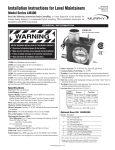
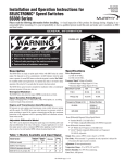
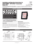
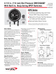
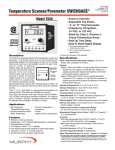
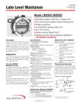
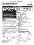
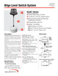
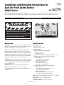
Installation and Operation Instructions for
Dual Set Point Speed Switch
HD-96044N
Revised 03-01
Section 20
(00-02-0179)
HD9063 Series
Please read the following information before installing. A visual inspection of this product for damage during shipping is recommended
before mounting. It is your responsibility to have a qualified person install this unit and make sure it conforms to NEC and local codes.
GENERAL INFORMATION
WARNING
BEFORE BEGINNING INSTALLATION OF THIS MURPHY PRODUCT
✔
✔
✔
✔
Disconnect all electrical power to the machine.
Make sure the machine cannot operate during installation.
Follow all safety warnings of the machine manufacturer.
Read and follow all installation instructions.
Description
Specifications
The HD9063 Series is a unitized two set point speed switch with
SPDT relay outputs. HD9063 is a PC-board configuration with
standoffs for mounting in a control panel or cabinet.
Power Supply:
Voltage: 8-30 VDC
Maximum Current: 150 mA
Frequency Signal:
Voltage, Magnetic Pickup Signal Models
• Minimum: 0.35 Vrms
• Maximum: 60 Vrms
Maximum Current, Magnetic Pickup Signal Models: 4.8 µA.
Adjustment Range, Magnetic Pickup Signal Models
• HD9063 Model
Crank Disconnect: 250-6,000 Hz
Overspeed: 1,100-10,000 Hz
• HD9063-USOS Model
Underspeed: 200-5,800 Hz
Overspeed: 1,100-10,000 Hz
Reset Differential, Magnetic Pickup Signal Models
• HD9063 Model
Crank Disconnect: Dropout 160 Hz ± 5%
Overspeed: 200 Hz Differential
• HD9063-USOS Model
Underspeed: +5% of Set point Differential
Overspeed: 155 Hz ± 10% Differential
Models are available for crank disconnect/overspeed and for
underspeed/overspeed applications. Trip points can be field
adjusted on all models. LED’s next to the set point potentiometers
indicate that the trip point has been reached and the relay(s) have
operated. An overspeed test circuit is built-in; it will actuate the
output relay at a point below actual overspeed set point.
The HD9063 can disconnect the starter on automatic start engine
applications and shutdown the engine if an overspeed situation
occurs. Re-engagement of the starter is inhibited until RPM
returns virtually to zero.
HD9063-USOS models allow operation of control circuits
according to the speed of the driver or as a pre-alarm.
Two separate adjustable speed switches are included on one
common board.
Output: Relay Contact, SPDT, Resistive Load: (2) 5 A, 30 VDC
Adjustment: (2) 270°–turn potentiometer
Temperature Range: 14 to 158°F (-10 to 70°C)
HD-96044N page 1 of 4
MOUNTING DIMENSIONS
HD9063 and HD9063-USOS
EAS
I
CR
CRANK
DISCONNECT
N
CR
EAS
E
2-1/4 in.
(57 mm)
Mounting
Holes
N
E
I
4 in. (102 mm)
Mounting Holes
OVERSPEED
EXT.
MAG.
PICKUP
INTERNAL
CRANK
DISCONNECT
RELAY
CONTACTS
EXT.
TEST
NC
NO
C
NC
NO
C
EXT.
POWER
2-3/4 in.
(70 mm)
INTERNAL
OVERSPEED
RELAY
CONTACTS
(+) ( ) (+) ( )
1 2 3 4 5 6 7 8 9 10 11 12
4-1/2 in.
(114 mm)
Mounting
Standoffs
4 Places
3/4 in.
(19 mm)
Mounting
1. Drill four 3/16 in. (5 mm) diameter mounting holes (refer to
mounting hole dimensions above).
2. Align the plastic standoffs on the HD9063 with the 4 mounting
holes and push gently until standoffs snap into place.
CAUTION: Pushing too hard could damage board.
Mounting
1. Drill four 1/4 in. (6 mm) diameter mounting holes (refer to mounting hole dimensions above).
2. Secure with four 10-32 screws.
RELAY FUNCTIONS
Crank Disconnect Relay
Overspeed and Underspeed Relay
An understanding of the crank disconnect function for your particular system is critical to speed switch installation. It is also
important to consider the 5 A current limitation of K1 relay contacts. Figure 1 illustrates the use of a low-current pilot relay to
operate the high-current starter solenoid. In operation, battery
voltage is supplied through the normally closed contacts of the
speed switch crank disconnect relay K1. When the engine starts,
K1 energizes and its normally closed contacts open. This action
de-energizes the pilot relay and inhibits the starter from operating
until the engine nearly stops. The normally open contacts may be
used if a contact closure is required to disable the cranking function for your system.
NOTE: Underspeed relay available on HD9063-USOS only.
The overspeed and underspeed functions of the speed switch may
be used in various systems to effect engine shutdown or actuate an
alarm in the event of engine overspeed or underspeed. Figure 2
illustrates the overspeed/underspeed function being used to control
a fuel rack solenoid. In this application, battery voltage is available
to the solenoid through normally open contacts of the relay (K2
overspeed) (K1 underspeed). If the engine speed exceeds the normal overspeed or underspeed set point, relay K1 or K2 energizes
and this voltage energizes the solenoid, shutting down the engine.
Similarly, the normally closed contacts may be used if engine shutdown is to be initiated by removal of battery voltage.
Underspeed Relay K1
NO
Crank
Disconnect Relay
K1
1
Overspeed Relay K2
NC
2
NO
3
1
NC
2
Contact opens on overspeed or
underspeed and drops out solenoid.
3
Battery
Crank
Enable
1
2
3
Energize
Starter
Pilot Relay
Battery
OPTIONAL
Off
Hold
NO
To
Starter Solenoid
Battery
Energize
Start
Figure 1
Starter
Switch
Starter Contactor
Relay
Figure 2
HD-96044N page 2 of 4
Starter
WIRING
CAUTION: PERFORM THE WIRING OPERATION WITH THE POWER SOURCE “OFF”
1. Connect terminal 5 on the HD9063 to engine ground and
connect terminal 4 to battery positive (see Figure 3).
2. Connect the magnetic pickup cable conductors to terminals
6 and 7.
3. If cable is shielded, connect shield to engine chassis ground.
4. If desired, connect a normally open test push button switch
between terminals 8 and 9.
5. Connect crank disconnect circuit to crank disconnect terminals 1 thru 3 as discussed in Crank Disconnect Relay
Function, page 2. On HD9063-USOS models connect the
overspeed circuits 1 thru 3 as discussed in Overspeed Relay
and Underspeed Relay Function, page 2.
6. Connect the overspeed circuits to overspeed terminals 10 thru
12 as discussed in Overspeed Relay and Underspeed Relay
Function, page 2.
(+) ( ) (+) ( )
1 2 3 4 5 6 7 8 9 10 11 12
K1
K2
12
To Engine
Crank Control
Circuit
or
to Shutdown
Circuits
(HD9063-USOS)
Common
Common
Normally Open
Normally Open
Normally Closed
Normally Closed
To
Shutdown
Circuits
Test
Pushbutton
DC Positive
DC Negative
(Engine Ground)
From Magnetic Pickup
Figure 3
MAGNETIC PICKUP INSTALLATION
A magnetic pickup is an AC generator. It is normally installed
into the flywheel housing of an internal combustion engine, so
that the starter ring gear acts upon it to generate a voltage pulse
each time a gear tooth passes the end of the sensor.
Gap Adjustment
Insert magnetic pickup and turn until it stops at the face of the gear.
Back-off the gear by turning the pickup counterclockwise 1/4, 1/2, or 3/4 turn (Figure 4) .
See Gap Chart (above, right) to determine gap
1/4
distance based on the turn. Check gap clearance by rotating the gear completely around.
NOTE: Magnetic pickup gap should be
1/2
3/4
adjusted so that the minimum voltage required
is attained at the engine’s lowest RPM. The
voltage will increase as the speed increases.
Figure 4
If erratic readings occur, remove magnetic
pickup and check the magnetic tip for metal chips.
THREAD
SIZE
TURN
1/4
1/2
3/4
1
5/8-18 UNF
.013 in.
(0.33 mm)
.028 in.
(0.71 mm)
.035 in.
(0.88 mm)
.055 in.
(1.39 mm)
3/4-16 UNF
.015 in.
(0.38 mm)
.030 in.
(0.76 mm)
.045 in.
(1.14 mm)
.062 in.
(1.57 mm)
GAP
Magnetic Pickup Installation (see Figure 5)
Drill and tap a hole in the flywheel housing (See Specifications
Chart below for model and thread size). IMPORTANT: Drilling
too deep may damage ring gear teeth. Blow chips with air hose
when drilling and tapping hole.
Gap Chart
Always use a two-conductor shielded cable. Ground the
shield to a metal frame ground at the engine end only.
Never run these wires
next to spark plug wires
or in wire loom with other
wires carrying inductive
loads or alternating current.
After adjusting,
set locknut.
Drill and tap casing
(see thread sizes in
Specifications).
AC
Meter
Gap
(see Gap Chart)
Casing
Murphy Magnetic Pickup Specifications Chart
Pickup
Model
Total
Length
Threaded
Length
MP3298*
MP7906†
MP7905††
3 in. (76 mm)
3 in. (76 mm)
4-1/2 in. (114 mm)
3 in. (76 mm)
3 in. (76 mm)
4-1/2 in. (114 mm)
Thread
Size
5/8-18 UNF
3/4-16 UNF
3/4-16 UNF
*Replaces 20-01-0080 and MP100. Lead wire hookup (12 in. [305 mm]).
†Replaces
20-01-0081. Lead wire hookup (12 in. [305 mm]).
20-01-0082. Lead wire hookup (12 in. [305 mm]).
††Replaces
HD-96044N page 3 of 4
NOTE: Clean gear casing
and magnetic sensor
of metal chips or filings.
Figure 5
Gear (must be made
of magnetic material).
ADJUSTING THE SPEED SWITCH
EAS
I
CR
N
CR
EAS
E
Crank
Disconnect
or
Underspeed
LED
N
E
I
Overspeed Potentiometer
Overspeed
LED
EXT.
MAG.
PICKUP
EXT.
TEST
NC
NO
C
NC
NO
C
EXT.
POWER
(+) ( ) (+) ( )
1 2 3 4 5 6 7 8 9 10 11 12
Figure 6
Crank Disconnect Set Point Adjustment
1. If engine serves as a backup for an electric pump or other
motor driven device, turn off the associated electric motor.
2. Reset any associated switches.
3. Ground engine ignition system or shut off fuel to engine to disable engine from starting.
4. Loosen locknut on Crank Disconnect set point potentiometer
and turn potentiometer fully clockwise.
5. Operate electrical switch(es) as appropriate so that engine will
begin to crank.
6. While engine is cranking, slowly turn Crank Disconnect Set
point potentiometer counterclockwise until Crank Disconnect
LED lights (Figure 6). Engine should stop cranking.
7. Now turn the potentiometer clockwise 1/16 turn.
8. Enable engine and allow it to start, verifying that starter disengages.
If starter motor stays engaged too long, lower set point slightly
by turning potentiometer counterclockwise in increments of no
more than 1/16 turn. Re-test after each adjustment by starting
engine, and continue adjustment until starter disconnects as
soon as engine starts.
If starter motor does not stay engaged long enough, raise set
point slightly by turning potentiometer clockwise in increments
of 1/16 turn. Re-test after each adjustment.
9. Tighten locknut on Crank Disconnect set point potentiometer.
NOTE: A starter protection feature prevents starter from being
engaged until engine almost completely stops after running.
MURPHY DE MEXICO, S.A. DE C.V.
Blvd. Antonio Rocha Cordero 300, Fracción del Aguaje
San Luis Potosí, S.L.P.; México 78384
+52 444 8206264 fax +52 444 8206336
Villahermosa Office +52 993 3162117
e-mail [email protected]
www.murphymex.com.mx
1. Loosen locknut on Overspeed set point potentiometer and turn
potentiometer fully clockwise.
2. Start engine and run at highest normal operating RPM.
3. Slowly turn Overspeed adjustment potentiometer counterclockwise until overspeed switch trips or engine shuts down.
The LED light should flash.
4. Turn potentiometer approximately 2° clockwise, then
tighten locknut.
5. Reset switches as applicable and restart engine.
NOTE: An overspeed test switch connected as shown in Figure 3
provides a means for decreasing set point for test purposes.
6. If a test push button is installed, press push button and verify
that overspeed LED (Figure 6) flashes and engine shuts down
or switch trips.
UNDERSPEED
NOTE: Underspeed is available on HD9063-USOS models only.
1. Loosen locknut on Underspeed set point potentiometer and turn
potentiometer fully counterclockwise.
2. Start engine and run at lowest normal operating RPM.
3. Slowly turn Underspeed adjustment potentiometer clockwise
until underspeed switch trips or engine shuts down. The LED
light should flash.
4. Turn potentiometer approximately 2° counterclockwise, then
tighten locknut.
5. Reset switches as applicable and restart engine.
NOTE: An overspeed test switch connected as shown in Figure 3
provides a means for decreasing set point for test purposes.
6. If overspeed test push button is installed, press push button and
verify that overspeed LED (Figure 6) flashes and engine shuts
down or switch trips.
Warranty
A limited warranty on materials and workmanship is given with this FW
Murphy product. A copy of the warranty may be viewed or printed by
going to www.fwmurphy.com/support/warranty.htm
FRANK W. MURPHY, LTD.
Church Rd.; Laverstock, Salisbury SP1 1QZ; U.K.
+44 1722 410055 fax +44 1722 410088
e-mail [email protected]
www.fwmurphy.co.uk
MURPHY SWITCH OF CALIFORNIA
41343 12th Street West
Palmdale, California 93551-1442; USA
+1 661 272 4700 fax +1 661 947 7570
e-mail [email protected]
www.murphyswitch.com
MACQUARRIE CORPORATION
1620 Hume Highway
Campbellfield, Vic 3061; Australia
+61 3 9358 5555 fax +61 3 9358 5558
e-mail [email protected]
RE
FW Murphy
P.O. Box 470248
Tulsa, Oklahoma 74147 USA
+1 918 317 4100
fax +1 918 317 4266
e-mail [email protected]
www.fwmurphy.com
CONTROL SYSTEMS & SERVICES DIVISION
P.O. Box 1819; Rosenberg, Texas 77471; USA
+1 281 633 4500 fax +1 281 633 4588
e-mail [email protected]
OVERSPEED
GI
D
Crank Disconnect
Underspeed Potentiometer
or (HD9063-USOS)
Potentiometer
Overspeed and Underspeed
Set Point Adjustment
E
Adjustment of the Dual Set point Speed Switch is performed
when the system is otherwise operational in all respects.
See Figure 6 for location of Crank Disconnect, Underspeed and
Overspeed potentiometers.
STER
USA–ISO 9001:2000 FM 28221
UK–ISO 9001:2000 FM 29422
In order to consistently bring you the highest quality, full featured products, we reserve the right to change our specifications and designs at any time.
Printed in U.S.A.
HD-96044N page 4 of 4