1
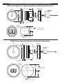
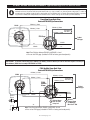
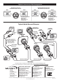
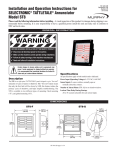
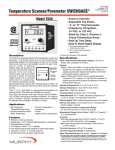
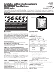
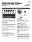
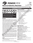
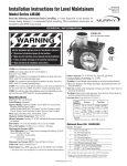
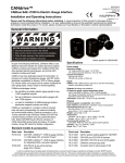
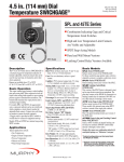
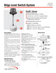
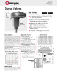
Analog Gages PVA20
& PVA35 Installation Instructions
PVA-02126N
Revised 01-04
Section 78
00-02-0532
Please read the following information before installing. A visual inspection of this product for damage during shipping is recommended before mounting. It is your responsibility to have a qualified person install this unit.
GENERAL INFORMATION
WARNING
BEFORE BEGINNING INSTALLATION OF THIS MURPHY PRODUCT
✔
✔
✔
✔
Disconnect all electrical power to the machine.
Make sure the machine cannot operate during installation.
Follow all safety warnings of the machine manufacturer.
Read and follow all installation instructions.
PVA35 Series
PVA20 Series
Specifications
Description
CAUTION: These instruments are designed to be used ONLY
with the MurphyLinkTM† PowerView module or other approved
MurphyLinkTM† PowerView products.
The PowerView Analog Gages (PVA) are a series of intelligent gages
designed to display easy-to-read information transmitted by the PowerView.
The PVA gages communicate with the PowerView via a single RS485 twisted pair MODBUS®† RTU serial link. The gages can be daisy-chained using
quick-connect harnesses with watertight connectors.
The PVA gages also include features such as a smooth stepper motor operation for the 270° sweep pointer, an environmentally sealed case with two
Deutsch DT style connectors molded into the casing, and green LED back
lighting. They are available for standard 2-1/16 in. (52 mm) and 3-3/8 in. (86
mm) diameter hole sizes. In addition their plastic cases incorporate a “D”
shape allowing panel cutouts that eliminate gage rotation during installation.
The PowerView Audible Alarm (PVAA) alerts operators to fault conditions
via piezoelectric alarm and relay contacts. It also has a temporary silencer
button that silences the audible tone for 2 minutes on alarms and 30 seconds
on shutdown conditions.
All PowerView Gages can be powered by 12 or 24 VDC systems.
PVA20 Series Models:
PVA20 –A
PVA20 –B
PVA20 –C
PVA20 –D
PVA20 –E
PVA20 –F
PVA20 –G
PVA20 –T
PVAA20
=
=
=
=
=
=
=
=
=
2 inch size gages:
Engine Oil Pressure
Coolant Temperature
Voltmeter
Percent Load at Current RPM
Transmission Oil Pressure
Transmission Oil Temperature
Engine Oil Temperature
Tachometer
2 inch dial audible alarm gage
PVA35 Series Models:
PVA35 –T
= Tachometer
3-1/2 in. size gages:
Power Supply Input Voltage: 12/24V (8-32VDC min. & max. voltage).
Power Supply Operating Current: (@ 14 VDC) =
PVA20, PVA35: 28 mA minimum; 52 mA maximum.
PVAA20: 19 mA minimum; 46 mA maximum.
Backlight Maximum Current (not applicable to PVAA20): 24 mA.
Input: RS485 MODBUS® RTU data.
Output: Analog Readout.
Relay Rated Load (PVAA20): 0.5 A, 125 VAC; 1 A, 24 VDC.
Relay Maximum Switching Capacity (PVAA20): 62.5 VA, 30W.
External Audible Alarm Output (PVAA20): 28 VDC, 30 mA max. (current sink).
Temporary Silence Button (PVAA20): Charge transfer technology.
Operating Temperature: -40° to 185°F (-40° to 85°C).
Storage Temperature: -76° to 185°F (-60° to 85°C).
Dial: White numerals over black background.
Indicating Pointer: Stepper motor operation with 270° sweep.
Gage Accuracy: PVA20: Better than ±1.0% of scale.
PVA35: Better than ±2% of scale.
Environmentally Sealed Enclosure:
Sealing: IP68, ±5 psi (±34.4 kPA).
Case and Clamp Material: Polyester (PBT).
Lens Material: Polycarbonate.
Bezel Material: Polyester (PBT).
Maximum Panel Thickness: 3/8 in. (9.6 mm).
Connectors: 6-Pin Deutsch DT06 Series.
†MurphyLink is a registered trademark of FWMurphy. All other trademarks and
service marks used in this document are the property of their respective owners.
PVA35 –S = Speedometer
PVA-02126N page 1 of 4
PVA SERIES20 and PVA SERIES35 Dimensions and Mounting
PVA20 and PVAA Series Typical Installation and Mounting Dimensions
2.430 in. (62 mm)
FRONT
Screw-on Type
Mounting Clamp
Deutsch DT
2 Push-on Type
Plug Connectors
Ø 2.324 in.
(59 mm)
1.956 in.
(50 mm)
2.050 in. (52 mm)
Gray Area shows Domed lens style
0.48 in. (12 mm)
BACK
2.062 in.
(52 mm)
diameter
HOLE CUTOUT
1.972 in.
(50 mm)
OR
Use a 2.062 in. (52 mm)
diameter round hole.
.953 in.
(24 mm)
0.125 in.
(3 mm)
R 0.063 in.
(1.6 mm)
PVA35 Series Typical Installation and Mounting Dimensions
2.475 in. (63 mm)
FRONT
Screw-on Type
Mounting Clamp
Ø 3.630 in.
(92 mm)
3.268 in.
(83 mm)
Deutsch DT
2 Push-on type
Plug Connectors
2.09 in. (53 mm)
Gray area shows
Domed Lens style.
BACK
0.48 in. (12 mm)
3.375 in.
(86 mm)
diameter
3.285 in.
(83 mm)
HOLE CUTOUT
OR
Use a 3.375 in. (86 mm)
diameter round hole.
1.610 in.
(41 mm)
0.125 in.
(3 mm)
R 0.063 in.
(1.6 mm)
PVA-02126N page 2 of 4
PVA20, PVA35 and PVAA SERIES Typical Wirings For 12 and 24 VDC
WARNING: Disconnect battery negative cable before wiring or service. Devices containing solid state components can be damaged or caused to
malfunction when used in systems which incorporate inductive loads (e.g. relays, solenoids, etc.) that can generate voltage spikes. To reduce the
potential for this type of damage, install a fly back or clamping diode across all inductive loads. Use Murphy diode package 65-00-0343 or equivalent.
A typical diode is 1N4005 and is readily available from commercial sources. Failures of this type are not covered by our Limited Warranty.
PowerView Gages Back View
Deutsch DT06-6S Style Connections
RS485 (+) Data
PV100
Pin 3
RS485 (+) Data
RS485 (-) Data
120 ohms
Pin 4
Pin 4
RS485 (-) Data See Note
Pin 3
PVA Gage
Pin 2
Pin 6
Pin 5
Pin 1
A
3
Pin 6
4
B
3
To Next
PVA gage
4
Pin 1
GRND
V+
1
GRND
6
1
6
V+
Note: Place Resistor between RS485+ and RS485– at end
of Line on last PVA gage (included in PVJR or factory purchased panels).
IMPORTANT: To eliminate external interference: RS485(+) and RS485(-) should be twisted pair cable or twist wires together, one twist per
inch minimum. (RS485 wire for example: BELDEN 9841 or 3105A).
PVAA Audible Alarm Back View
Deutsch DT06-6S Style Connections
PV100
RS485 (+) Data
Pin 3
RS485 (+) Data
RS485 (-) Data
120 ohms
Pin 4
RS485 (-) Data See Note
PVAA
Audible
Alarm
Pin 1
3
V+
Ignition
Switch
A
4
B
3
To Next
PVA gage
4
5
Pin 1
Pin 6
V+
GRND
GRND
1
1
6
6
V+
5
+
Optional Alarm
Horn or Power
– Relay Coil
V+
Battery
– Optional
External Alarm
+ or FWMurphy
Mini-Siren® SAH
Note: Place Resistor between RS485+ and RS485– at end
of Line on last PVA gage (included in PVW-P or factory purchased panels).
PVA-02126N page 3 of 4
Typical Connectors PIN Designation
PowerView Gages Back View
Deutsch DT06-6S Style Connections
Plug A
PIN 3
RS485 +
PowerView Audible Alarm Back View
Deutsch DT06-6S Style Connections
Plug A
Plug B
PIN 3
RS485 +
PIN 4
RS485 –
A
PIN 6
GRND
PIN 1
V+
PIN 3 RS485 +
PIN 4 RS485 –
PIN 2
Relay
COM
B
PIN 6
GRND
PIN 1
V+
PIN 3 RS485 +
PIN 4
RS485 –
Plug B
PIN 5
Relay
N.O.
PIN 1 V+
A
PIN 4 RS485 –
PIN 2
Relay
N.C.
B
PIN 6 GRND
PIN 5 Ext.
Audible
Alarm
PIN 6 GRND
PIN 1 V+
Recommended Connectors:
Recommended Connectors:
Body: Deustch DT06-6S
Wedge Lock: W6S
Terminals: 0462-201-16141
Sealing Plug: 114017
Body: Deustch DT06-6S
Wedge Lock: W6S
Terminals: 0462-201-16141
Sealing Plug: 114017
Typical Quick-Connect Diagram
Last PVA Gage or
PVAA Audible Alarm
To Engine
ECU
A
To optional
external device
To PVAA
Audible Alarm
B
Terminating
Resistor PVJR
To Battery
Power
PVW-CH
POWERVIEW
PV100
A
Relay N.O.
B
Relay N.C.
OR
Ext.
Sonalert
PVW-PH
Relay Comm.
Optional PVW-A wire harness
Customer provided wire
harness or CAN extension
harnesses or power
extension harnesses.
(includes terminating resistor)
A
B
PVA Gage
Next PVA Gage
Wire harness
PVW-J
External Dimmer
Wire 24 inch.
A
External
Dimmer
B
A
B
B+
GRND
CAN–SHLD
CAN–LO
CAN–HI
Wire harness PVW-P
Wire harness PVW-J
Wire harness PVW-J
Warranty
A limited warranty on materials and workmanship is given with this FW Murphy product.
A copy of the warranty may be viewed or printed by going to www.fwmurphy.com/support/warranty.htm
GI
D
MURPHY SWITCH OF CALIFORNIA
41343 12th Street West
Palmdale, California 93551-1442; USA
+1 661 272 4700 fax +1 661 947 7570
e-mail [email protected]
www.murphyswitch.com
MACQUARRIE CORPORATION
1620 Hume Highway
Campbellfield, Vic 3061; Australia
+61 3 9358 5555 fax +61 3 9358 5558
e-mail [email protected]
E
MURPHY DE MEXICO, S.A. DE C.V.
Blvd. Antonio Rocha Cordero 300, Fracción del Aguaje
San Luis Potosí, S.L.P.; México 78384
+52 444 8206264 fax +52 444 8206336
Villahermosa Office +52 993 3162117
e-mail [email protected]
www.murphymex.com.mx
FRANK W. MURPHY, LTD.
Church Rd.; Laverstock, Salisbury SP1 1QZ; U.K.
+44 1722 410055 fax +44 1722 410088
e-mail [email protected]
www.fwmurphy.co.uk
RE
FW Murphy
P.O. Box 470248
Tulsa, Oklahoma 74147 USA
+1 918 317 4100
fax +1 918 317 4266
e-mail [email protected]
www.fwmurphy.com
CONTROL SYSTEMS & SERVICES DIVISION
P.O. Box 1819; Rosenberg, Texas 77471; USA
+1 281 633 4500 fax +1 281 633 4588
e-mail [email protected]
STER
USA–ISO 9001:2000 FM 28221
UK–ISO 9001:2000 FM 29422
In order to consistently bring you the highest quality, full featured products, we reserve the right to change our specifications and designs at any time.
PVA-02126N page 4 of 4
Printed in U.S.A.