1
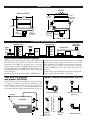
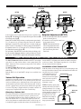
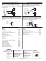
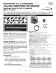
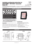
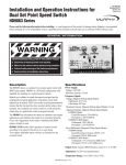
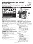
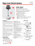
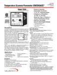
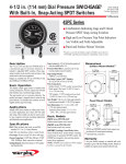
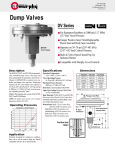
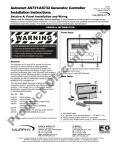
Installation and Operation of the
DF Series Hydrostatic Head Level Switches
DF-94063N
Revised 09-03
Section 15
(00-02-0170)
Please read the following information before installing. A visual inspection of this product for damage during shipping is recommended before mounting. It is your responsibility to have a qualified person install this unit and make sure it conforms to NEC
and local codes.
GENERAL INFORMATION
*
WARNING
**
BEFORE BEGINNING INSTALLATION OF THIS MURPHY PRODUCT
✔
✔
✔
✔
Disconnect all electrical power to the machine.
Make sure the machine cannot operate during installation.
Follow all safety warnings of the machine manufacturer.
Read and follow all installation instructions.
CAUTION: Certain dangers to human safety and to equipment may occur if some equipment is stopped without
pre-warning. It is recommended that monitored functions
be limited to alarm only or to alarm before shutdown.
Description
Specifications
The DF series are diaphragm operated “hydrostatic head pressure”
level switches. A pressure sensitive diaphragm operates a snap-switch
that can be wired directly to electric pilot circuits to control pumps at
predetermined levels. Typical application is to start and stop electric
driven pump(s) to maintain tank levels. It is also applicable to engine
driven pumps.
The Nitrile sensing diaphragm is impervious to most liquids and is
sensitive enough to control levels with 1/4 in. (6 mm) repeatability.
See model descriptions for limits of switch trip point adjustability.
Materials include aluminum body, nylon bottom plate and a special
alloy leaf snap-switch as standard.
This simple level switch is highly reliable and can be worked into most
new or existing system without major modification or special tools.
DF755 and DF757 are suitable for atmospheric tanks in a non-hazardous location.
The SPDT snap-switch for the DF755 is preset for a 4 in. (102 mm)
differential in liquid level, operating at approx. 6 inches (152 mm) rising, and resetting at approx. 2 inches (51 mm) falling level.
The DF757 trip point is adjustable over a 108 inches (2743 mm) differential.
Snap-switch Ratings
SPDT (standard–all models)
• 5 A @ 125, 250, or 480 VAC
• 1/2 A @ 125 VDC, 1/4 A @ 250 VDC
Case/Lid: Aluminum (standard); all non-explosion proof models.
Bottom Plate: Glass-filled nylon.
Process Connection: 1 NPT (standard)
Maximum Pressure Rating: 25 psi (172 kPa) [1.72 Bar].
Conduit Connection (electrical): 1/2 NPT.
Warranty
A limited warranty on materials and workmanship is given with this FW
Murphy product. A copy of the warranty may be viewed or printed by going
to www.fwmurphy.com/support/warranty.htm
DF-94063N page 1 of 4
DIMENSIONS
DF755EX
DF755 and DF757
5-1/2 in.
(140 mm)
1/2 NPT
For Electrical
Connection
7-21/32 in.
(194 mm)
6-5/32 in.
(156 mm)
1/2 NPT
Plug
1 NPT
(standard)
1/2 NPT
For Electrical
Connection
1/4 in. (6 mm)
Tube Fitting
(DF756 only)
1 NPT
(standard)
5-5/8 in.
(143 mm)
TYPICAL APPLICATIONS
Raw Water Tank
DF#1
Supply
Pump
Clear Water Tank
Transfer
Pump
DF#5
DF#2
DF#3
OPL Series
SWICHGAGE®
Injection Pump
DF#6
Filter
DF#7
DF#4
DF#8
Typical Water Flood Control System
The diagram above displays eight DF Series switches installed on a
Raw Water tank and a Clear Water tank. When raw water rises to
predetermined level, DF#1 stops the supply pump. As tank level
falls below the predetermined level, DF#2 starts the supply pump. If
the tank level continues to fall, DF#3 initiates shutdown of the supply pump. DF#4 stops transfer pump before raw water tank is completely pumped out.
When clear water reaches the predetermined level, DF#5 stops the
transfer pump. As tank level falls to predetermined low level, DF#6
starts the transfer pump. If the tank level continues to fall due to the
failure of the filters section, DF#7 initiates shutdown of the transfer
pump. (DF755 located at this level will also operate backwash
equipment). DF#8 stops injection pump before tank pumps completely out.
An OPL Series pressure SWICHGAGE® stops injection pump when
pressure reaches predetermined high or low pressure.
Tank with Low Pressure
Gas Blanket (DF755EX)
Typical Tank Mounting Methods (DF755)
The DF755EX (below) is shown installed on a crude oil tank where
a low pressure gas blanket is used to prevent evaporation loss. It is
mounted directly to the side of the tank or on riser pipe 4 to 7 in.
(102 to 178 mm) below level to be controlled. Pump automatically
stops or starts when liquid reaches predetermined high or low level.
Bull Plug Installation
Tank Wall Mounting With
Drain Cock
Fuel Tank
Gas Blanket
Gas Liquid
Directly
On Tank
DF-94063N page 2 of 4
Riser Pipe
Method
Tank Wall Mounting
BASIC OPERATION
DF755EX
DF755
DF757
C
C
B
C
B
B
Vent (DF755EX)
or Tube Fitting
(DF756)
A
A
D
A
Hydrostatic Head
Pressure
Hydrostatic Head
Pressure
As the liquid level rises, hydrostatic head pressure is applied to the
diaphragm A. The diaphragm is forced upward forcing the actuator arm B
to activate the snap-switch C.
Models DF755 and DF755EX are factory set and operate at approximately
2 in. (51 mm) and 6 in. (152 mm) rising above the level at which the
diaphragm is mounted. The switch resets back to normal condition at
approx. 2 inches (51 mm) falling level. The trip point(s) for Model DF757
are adjustable between 2 in. (51 mm) and 110 in. (2794 mm) for high and
low (make/break) operation by knobs, D.
For sealed tanks, model DF755EX can be fitted with a tube fitting to balance the top of the diaphragm chamber to a tank gas blanket (see Typical
Applications). The DF755EX is supplied with an atmospheric vent fitting.
Hydrostatic Head
Pressure
Setpoint Adjustment (DF757)
1. Locate threaded adjustment shaft and adjustment
knobs (see drawing above).
2. To increase low level setpoint, rotate lower
knob counterclockwise.
NOTE: If adjustment shaft turns
Adjustment
when rotating adjustment knobs,
Shaft
grasp the adjustment shaft with a
pair of needle nose pliers–then
rotate knob.
USING THE DF755 WITH MAC1 VOLUME CELL ACCESSORY
The MAC1 Volume Air Cell when attached to the DF755 can monitor
water levels on a sump. Activate alarms or start a pump directly. The
MAC1 Volume Air Cell is non-corrosive and provides 1/4-20 stainless
steel mounting studs.
The MACT1 Tubing Kit provides 4 ft. (1.2 m) flexible, non-corrosive
1/4 in. (6 mm) tubing (cut to fit). The kit includes necessary fittings to
attach tubing.
Both the MAC1 air cell and MACT1 tubing kit are available from
Murphy.
Volume Cell Operation
As liquid rises around the volume cell, it compresses air inside the cell
and forces it up in the sensor line. As air pressure increases due to the
water level continuing to rise, sufficient pressure will be applied to activate the internal snap-switch, which in turn starts the pump. As the liquid level is pumped down, pressure decreases and the above procedure
is reversed. The pump is stopped and held in a standby condition. An
air purge may be required in the sensor line. Consult factory.
Installation of the Volume Cell
Install the volume cell according to the level you wish the pump to start
and stop. Secured the volume cell with a substantial bracket which will
not allow the cell to be “floated”
or tilted when the water level
DF755
rises. The DF755 should be
installed well above the highest
water level and in a position
that will allow access for
adjustment or repair.
NOTE: Periodically operate pump
manually until water level reaches a
point approximately 1/2 in. (13 mm)
below bottom of the volume cell. This
will automatically re-charge the unit
and compensate for normal
absorption of air into water.
Small electric air pumps are
available to automatically
charge system at all times.
DF-94063N page 3 of 4
Sensor Line
(MACT1 Tube Kit)
Volume Cell
(MAC1)
AIR
Choosing a Volume Cell
The volume cell should be constructed of material which will be unaffected by the liquid being measured. For proper “pressure-to-level”
ratio, the minimum dimensions of the volume cell should be 6 in. (152
mm) inside diameter and 3 in. (76 mm) inside depth. The sensor line
can be of any diameter or material either flexible, or solid, as long as it
is of sufficient length to reach from the volume cell to the desired loca-
tion for the DF755. All fittings and connections should be air-tight to
avoid loss of “charge”. Tube lengths longer than 4 ft. (1.2 m) should
have provision for periodic air purging.
TYPICAL WIRING
Starts at Low Level, Stops at High
Starts at High Level, Stops at Low
Start motor when predetermined low level is reached and stop when high
level is reached. Keeps tank level within selected limits. Motor starter
equipped with H.O.A.
HIGH
Start motor when predetermined high level is reached and stop when low level
is reached. Motor starter equipped with H.O.A.
HIGH
N.O.
N.O.
C
DF755
#1
N.C.
N.C.
N.O.
N.O.
C
DF755
#2
DF755
#2
C
N.C.
LOW
N.C.
MOTOR
LOW
MOTOR
DF755
#1
C
Single Magneto Shutdown
Dual Magneto Shutdown
Wiring of magneto to N.O. switch terminal will shut down engine at predetermined high level, shown below. Wire to N.C. terminal to shutdown on
low level.
Shutdown dual magneto engines using Murphy MS2120 Magnetic Switch.
Diagram below shows hookup for low level shutdown. Wiring changes and
mounting locations are necessary for high level shutdowns.
MAGNETO
Model MS2120
Magneto
N.O.
C
N.C.
Magneto
6 1
2
3
4 5
N.O.
C
N.C.
Jumper #2 & #5
SERVICE PARTS
DF755
DF757
Description
Cover (aluminum)
Case (aluminum)
Cover Screws (3), #6–32 x 5/16 round head
SPDT snap-switch and movement assembly/repair kit (5 amp)
Screws (3) for switch assembly to case, #6–32 x 1/4 round head
Diaphragm repair kit
Bottom Plate (1 NPT connection)
Bracket and movement repair kit
SPDT snap-switch and insulator repair kit (5 amp)
Part Number
15050081
15050082
80040607
15000122
80040605
15000123
15050083
15000313
15000121
Cover (aluminum)
Case (aluminum)
Cover Screw (3), #6–32 x 5/16 round head
SPDT snap-switch and bracket assembly/repair kit (5 amp)
Screws (2) for switch bracket and assembly to case (#6–32 x 1/4 round head)
Spring and piston assembly/repair kit
Diaphragm repair kit
Bottom Plate (1 NPT connection)
SPDT snap-switch and insulator repair kit (5 amp)
15050081
15050594
80040607
15000174
80040605
15000190
15000123
15050083
15000230
DF755EX
MURPHY DE MEXICO, S.A. DE C.V.
Blvd. Antonio Rocha Cordero 300, Fracción del Aguaje
San Luis Potosí, S.L.P.; México 78384
+52 444 8206264 fax +52 444 8206336
Villahermosa Office +52 993 3162117
e-mail [email protected]
www.murphymex.com.mx
FRANK W. MURPHY, LTD.
Church Rd.; Laverstock, Salisbury SP1 1QZ; U.K.
+44 1722 410055 fax +44 1722 410088
e-mail [email protected]
www.fwmurphy.co.uk
MURPHY SWITCH OF CALIFORNIA
41343 12th Street West
Palmdale, California 93551-1442; USA
+1 661 272 4700 fax +1 661 947 7570
e-mail [email protected]
www.murphyswitch.com
MACQUARRIE CORPORATION
1620 Hume Highway
Campbellfield, Vic 3061; Australia
+61 3 9358 5555 fax +61 3 9358 5558
e-mail [email protected]
GI
D
CONTROL SYSTEMS & SERVICES DIVISION
P.O. Box 1819; Rosenberg, Texas 77471; USA
+1 281 633 4500 fax +1 281 633 4588
e-mail [email protected]
RE
FW Murphy
P.O. Box 470248
Tulsa, Oklahoma 74147 USA
+1 918 317 4100
fax +1 918 317 4266
e-mail [email protected]
www.fwmurphy.com
15050154
15050155
15050305
15000118
80040605
15000119
15000123
15050083
80040814
00000827
86060203
85030402
86060801
15000117
E
Cover (aluminum)
Case (aluminum)
Gasket
SPDT snap-switch and movement assembly/repair kit (5 amp)
Screws (2) for switch assembly to case, #6–32 x 1/4 round head
Actuator assembly/repair kit
Diaphragm repair kit
Bottom Plate (1 NPT connection)
Screw (1), #8–32 x 1/4 round head
Terminal cup washer
Plug 1/8 plastic pipe hex (DF755EX)
Connector, 1/4 tube x 1/8 pipe male (DF756)
Plug 1/2 NPT hex (brass)
SPDT snap-switch and insulator repair kit (5 amp)
STER
USA–ISO 9001:2000 FM 28221
UK–ISO 9001:2000 FM 29422
In order to consistently bring you the highest quality, full featured products, we reserve the right to change our specifications and designs at any time.
Printed in U.S.A.
DF-94063N page 4 of 4