1
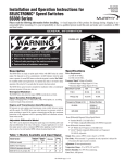
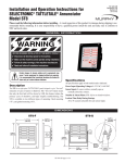
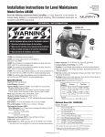
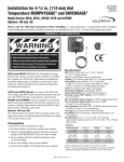
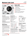
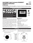
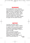
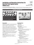
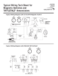
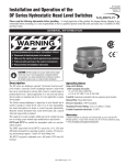
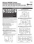
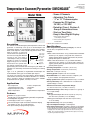
Temperature Scanner/Pyrometer SWICHGAGE®
Model TDX6
TDX-9106B
Revised 11-02
Catalog Section 10
(00-02-0049)
• Scans 6 Channels
• Adjustable Trip Points
• “J” or “K” Thermocouples
• Powered by CD Ignition,
24 VDC, or 120 VAC
• Rated for Class I, Division 2,
Group D Hazardous Areas
• Start-up Time Delay
• Easy to Read Digital Display
Approved *
Approved **
* When used with approved ignition.
Contact Murphy for details.
** When used with power requirements
described below.
Description
■
The TDX6 is an advanced design 6-point temperature scanner and
pyrometer. It continually scans up to six thermocouples and
sequentially displays the thermocouple number and its reading.
Each sensor input has a field settable trip point for alarm, shutdown or control. A read/scan
Easy to Read
selector allows the operator to set
Digital Display
and view each trip point. With the
Thermocouple
selector in the scan mode, a
Read
“thermocouple read” push button
Trip Point
provides a means to manually
Read/Scan
toggle through the six channels
Trip Point
Adjustment
and to lock in on a specific channel. Normal scanning will resume
approximately three seconds after releasing the push button. All
trip points are continually armed and active during the scanning
process.
Type “J” or “K”, grounded† or ungrounded thermocouples are
accommodated. Other types are available upon request.
The TDX6 can interface with other Murphy SELECTRONIC®
TATTLETALE® annunciators and Micro-controllers. It is rated for
Class I, Division 2, Group D, hazardous areas* and is available
for operation from CD ignition, 120 VAC, or 24 VDC .
Specifications
Applications
• Gas Compressor
•
Suction/Discharge Temp.
Engine/Compressor Jacket
Water Temperature
• Process Temperatures
• Generators
• Pumps
• Engine Exhaust Temperature
Features
■
■
■
■
■
■
■
Monitors six (6) input sensors
Accepts type “J” or “K” thermocouples grounded† or ungrounded
Field adjustable trip points
LCD display in either °F or °C (specify)
One thermocouple maybe selected for continuous display
CD ignition, 24 VDC, or 120 VAC powered
No special training or programming required
Scans all 6 sensors in 30 seconds
Power Requirements (Operating Voltages): 120 VAC or
80-250 VDC, CD ignition or 24 VDC.
Outputs:
Models TDX6-A and TDX6-C: Six (6) isolated Silicon Controlled
Rectifier (S.C.R.) outputs; 0.5 A @ 250 VDC; switches on
(applies ground) above trip point and switches off (removes
ground) when power is switched off.
Models TDX6-B and TDX6-D: Six (6) isolated Field-Effect
Transistor (F.E.T.) outputs; 0.1 A @ 250 VDC; switches on
(applies ground) above trip point and switches off (removes
ground) below trip point.
Operating Temperature: -4 to 158°F (-20 to 70°C).
Storage Temperature: -40 to 300°F (-40 to 150°C).
Case: ABS 1/4 DIN (90 x 90 mm).
Scanning Speed: Complete scan in 30 seconds.
Reset Differential: F.E.T. models: Decreases 3 Degrees (°F or
°C). S.C.R. models: Turn input power off to reset.
Display Update Time: Updates temperature every 0.3 seconds.
Start-up Time Delay: Unit is locked out for 10 seconds after
ignition voltage is sensed.
Ambient Cold Junction Compensation Range:
2°F from 32°F to 122°F (1°C from 0°C to 50°C).
Measurement Range: Monitor Range 0-1999°F or °C (specify °F
or °C in part number).
Accuracy:
With J-type thermocouple: from 50-150°F (10-66°C) +3°F(+2°C),
from 150-1200°F (66-649°C) ±1.0% of reading.
With K-type thermocouple: from 400-2000°F (204-1076°C)
±1.0% of reading.
Trip Point Accuracy: ±3°F (±2°C) of reading.
Trip Point Adjustment Range: 0-1999 Degrees.
Open Thermocouple Input: A number 1 appears in the display
thegrounded
right ofthermocouples
the channelintroduces
numbertheand
the
pointoroperates.
Using
risk of
oddtrip
currents
voltages
†to
being imposed on the thermocouple signal which can affect the accuracy of the
reading. This is an inherent problem of grounded thermocouples, the reason why
we prefer ungrounded thermocouples.
Dimensions
Side View
Typical Wiring Diagram
Back View
4-5/8 in.
(117 mm)
3
3-1/2 in.
(89 mm)
1 INPUT
JUMPER
POWER INPUT
5
Mounting Clamp
Load
2
TC 1
3-3/4 in.
(95 mm)
TC 2
TC 3
TC 4
4-3/8 in.
(111 mm)
3-3/4 in.
(95 mm)
6-3/4 in.
(171 mm)
clearance for plug
TC 5
TC 6
Mounting Hole
4-3/4 in. (121 mm)
diameter
NOTES:
1 Remove
input jumper when the thermocouple is
connected to input.
2 Thermocouple Input
3-9/16 in.
(90 mm)
3
3-9/16 in.
(90 mm)
LCDT,
MARK II,
S1400,
TATTLETALE ® etc.
TDX6
Round Hole Mounting (TDXF6)
Square Hole Mounting
+ 4
+ TP 1 +
+
- COM - TC 1
+
PWR TP 2 +
- TC 2 INPUT TP 3 +
+
COM - TC 3
TP 4 +
+
TP 5 +
- TC 4
COM +
TP 6 +
- TC 5
COM +
TC
6
-
120
120
Power input 120 VAC, 80-250 VDC, CD ignition or 24 VDC,
positive or negative ground.
Interfaced components must meet area
classification requirements.
5 When using the TDX6 with inductive loads, we recommend
installing a suppression diode across all coils.
4
1/4 in. (6 mm) dia.
holes (3 places)
120
How to Order
To order the TDX6 use the part number designation diagram below.
Shipping Weight: 2 lb. (0.91 kg).
Shipping Dimensions: 5-1/2 x 9 x 6 in. (140 x 229 x 152 mm).
TDX6 – A – F – J
TDX6 Interface Capabilities
Thermocouple Type
J = Type J
K = Type K
Display
F = Fahrenheit
C = Celsius
Power Supply/Output
A = CD ignition, 80-250 VDC Positive or Negative Ground or
120 VAC 50-60 Hz Inputs—S.C.R. Outputs.†
B = CD ignition, 80-250 VDC Positive or Negative Ground
or 120 VAC 50-60 Hz Inputs—F.E.T. Pulsed Outputs.††
C = 24 VDC Inputs—S.C.R. Outputs.†
D = 24 VDC Inputs—F.E.T. Pulsed Outputs.††
Rating
Cl.I, Div.1, Gr. D, Haz. areas*
S1501
120 VAC or 12/24 VDC
Cl.I, Div.1, Gr. D, Haz. areas*
MARK II
CD Ignition, pos. or neg. grnd
Cl.I, Div.2, Gr. D, Haz. areas*
CD Ign., 120 VAC, 12/24 VDC
Non-Hazardous areas
TATTLETALE
®
PLC’s, various non-Murphy annunciators–contact factory.
*Note: An isolation barrier is needed between the TDX6 and an Annunciator rated
for Class I, Division 1, Group D, Hazardous Areas.
**Note: When used with approved ignition. Contact Murphy for details.
Warranty
A limited warranty on materials and workmanship is given with this FW
Murphy product. A copy of the warranty may be viewed or printed by going to
www.fwmurphy.com/support/warranty.htm
CONTROL SYSTEMS & SERVICES DIVISION
P.O. Box 1819; Rosenberg, Texas 77471; USA
+1 281 633 4500 fax +1 281 633 4588
e-mail [email protected]
MURPHY SWITCH OF CALIFORNIA
41343 12th Street West
Palmdale, California 93551-1442; USA
+1 661 272 4700 fax +1 661 947 7570
e-mail [email protected]
www.murphyswitch.com
MACQUARRIE CORPORATION
1620 Hume Highway
Campbellfield, Vic 3061; Australia
+61 3 9358 5555 fax +61 3 9358 5558
e-mail [email protected]
RE
MURPHY DE MEXICO, S.A. DE C.V.
Blvd. Antonio Rocha Cordero 300, Fracción del Aguaje
San Luis Potosí, S.L.P.; México 78384
+52 444 8206264 fax +52 444 8206336
Villahermosa Office +52 993 3162117
e-mail [email protected]
www.murphymex.com.mx
FRANK W. MURPHY, LTD.
Church Rd.; Laverstock, Salisbury SP1 1QZ; U.K.
+44 1722 410055 fax +44 1722 410088
e-mail [email protected]
www.fwmurphy.co.uk
GI
D
†For use with electromechanical TATTLETALE® annunciators.
††For use with SELECTRONIC® or similar solid-state annunciators.
FW Murphy
P.O. Box 470248
Tulsa, Oklahoma 74147 USA
+1 918 317 4100
fax +1 918 317 4266
e-mail [email protected]
www.fwmurphy.com
Power Source
CD Ign., 120 VAC, 12/24 VDC
E
Models
TDX6 = Square hole mounting
TDXF6 = Round hole mounting
Model
LCDT
STER
USA–ISO 9001:2000 FM 28221
UK–ISO 9001:2000 FM 29422
In order to consistently bring you the highest quality, full featured products, we reserve the right to change our specifications and designs at any time.
Printed in U.S.A. 0591127
TDX-9106B page 2 of 2