1
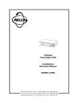
TIME LAPSE VIDEO CASSETTE RECORDER
INSTALLATION AND
OPERATION MANUAL
MODEL
HS-S8300E(BRS)
POWER
REC
EJECT
STOP
S-VHS
OFF
ON
PICTURE
DISPLAY
SOFT
SHARP
POSITION/
TRACKING VERTICAL
ADJUST
COUNTER
RESET
COUNTER MEMORY/
SKIP/INDEX
REC/PLAY
MODE
TIMER REC
JOG/ADJUST
SHUTTLE
CLEAR/
ENTER/
REW
FF
PLAY
PAUSE/
SHUTTLE HOLD
VHS
PAL
625
ONLY VIDEO CASSETTE TAPES WITH THE S MARK OR THE V MARK MAY BE USED WITH THIS MODEL.
THIS INSTRUCTION MANUAL IS IMPORTANT TO YOU.
PLEASE READ IT BEFORE USING YOUR VIDEO CASSETTE RECORDER.
CAUTION AND CARE
CONDENSATION IS THE ENEMY OF VIDEO RECORDERS
2 WHAT IS CONDENSATION?
1. When a very cold drink is poured into a glass, the water droplets which form on the outer surface of the glass are an example of
condensation.
2. If the VCR is exposed to a rapid increase in temperature (such as warming a cold room or after transporting it from a cold location
to a warm one) condensation may form on the tape transport mechanism inside the VCR. To prevent damage to the VCR or tapes,
plug the VCR into the mains outlet and turn the power on for about 2 hours. Do not use the VCR for playback or record during this
time.
2 CONDENSATION IS LIKELY TO OCCUR WHEN:
1. The VCR is moved inside from outdoors, or from a cold room to a warm one.
2. A cold room is heated quickly.
3. Humidity is high.
N
• Avoid using the VCR where cold air (e.g., from an air conditioner) will blow directly on it.
• Never place anything containing water on top of the VCR, e.g., vases, cups, etc.
HEAVY OBJECTS (E.G., TV) SHOULD NEVER BE PLACED ON THE VCR
CABINET CARE
Never use petroleum-based cleaners. Clean with a soft cloth
moistened with soap and water and wipe dry. PVC cables or leads
should not be left in contact with the cabinet surface for long periods.
UNPLUGGING THE MAINS LEAD
Whenever unplugging the mains leads, be sure to switch off the
mains outlet first. Then unplug the lead by gripping the plug (not
the lead) and carefully remove the plug from the mains outlet.
NEVER TOUCH OR INSERT ANY OBJECT INSIDE THE VCR
Touching the inside of the cabinet or inserting foreign objects of
any kind not only creates a safety hazard but can also cause extensive damage.
INSTALLATION LOCATION
For optimum performance and reliability, install the VCR in a location that is:
1. Well ventilated, out of direct sunlight and away from direct heat.
2. A solid vibration-free surface.
3. Free from high humidity, excessive dust and away from magnetic fields.
PROTECT THE MAINS LEAD
Damage to the mains lead may cause fire or shock hazard.
UNPLUG THE MAINS LEAD DURING A LONG ABSENCE
During a long absence, turn off the power and switch off the mains
outlet before unplugging the mains lead.
N
• Never move the VCR without first removing the tape.
MAINTAIN GOOD VENTILATION
Do not obstruct the many ventilation holes on the VCR. For maximum ventilation, place the unit on a hard level surface only, and
ensure it is not covered during use. Heavy objects should never
be placed on the VCR.
CARE OF VIDEO CASSETTE TAPES
• Avoid violent vibration or shock.
• Do not place near a strong magnetic field (e.g., a motor, transformer or magnet).
• Never place or store in direct sunlight.
• Avoid dusty places.
• Place the cassette in its case and store vertically.
WHEN NOT IN USE
When you finish operating the VCR always unload the cassette
and turn OFF the VCR POWER.
2 MAINS LEAD CONNECTION
The mains lead on this VCR is fitted with a non-rewireable
mains plug, incorporating a 5A fuse. If you need to replace
the fuse, use a 5A fuse approved by BSI or ASTA to BS 1362,
ensuring you refit the fuse cover. If the mains plug is not suitable for the sockets in your home, buy a new mains lead. If
you require to remove the plug, remove the fuse, cut off the
plug then dispose of the plug immediately, to avoid a possible
electric shock hazard. To refit a new plug, follow these instructions;
Green-and-yellow: Earth,
Blue: Neutral,
Brown: Live
As the colours in the mains lead of this VCR may not correspond with the coloured markings identifying the terminals in
your plug, proceed as follows.
• The wire which is coloured green-and-yellow must be connected to the terminal in the plug which is marked by the letter
E or by the safety earth symbol » or coloured green or greenand-yellow.
• The wire which is coloured blue must be connected to the terminal which is marked with the letter N or coloured black.
• The wire which is coloured brown must be connected to the
terminal which is marked with the letter L or coloured red.
WARNING:
TO PREVENT FIRE OR SHOCK HAZARD, DO
NOT EXPOSE THIS APPARATUS TO RAIN OR
MOISTURE.
WARNING:
THIS APPARATUS MUST BE EARTHED.
This Time Lapse Video Cassette Recorder complies with the requirements of the EC Directive 89/336/EEC, “EMC Directive” and
73/23/EEC, “Low Voltage Directive”, as amended by Directive 93/
68/EEC. The requirements for the susceptibility according to EN
50082-1 and the requirements for interference according to EN
55022 are observed for the operation on residential areas, business, light industrial premises and in small scale enterprises, inside as well as outside of the building. All places of operation are
characterised by their connection to the public low voltage power
supply system.
This unit is manufactured in accordance with EN60065.
2
CONTENTS
Pages
Elapsed time display ............................................................ 19
TIMER RECORDING ....................................................... 20 - 21
ALARM RECORDING ..................................................... 22 - 24
Alarm recording connection ................................................. 22
External time clock adjustment ............................................ 22
Setting for alarm recording .................................................. 23
Emergency recording ........................................................... 23
Alarm record time display .................................................... 24
Locating the start of alarm recordings ................................. 24
PLAYBACK ............................................................................. 25
Audio playback ..................................................................... 25
SPECIAL EFFECTS PLAYBACK ........................................... 26
ADJUSTMENT DURING PLAYBACK
Tracking adjustment ............................................................. 27
Picture quality adjustment .................................................... 27
Vertical adjustment .............................................................. 27
USING WITH THE PERSONAL COMPUTER ................. 28 - 36
WARNING DISPLAY ............................................................... 37
BEFORE CALLING FOR SERVICE ....................................... 38
CONTROL INPUT/OUTPUT SIGNALS AND CIRCUITS ..... 39 - 40
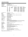
SPECIFICATIONS .................................................................. 41
Pages
FEATURES AND FUNCTIONS
Front view ............................................................................... 4
Fluorescent display ................................................................. 5
Rear view ................................................................................ 6
CONNECTING WITH OTHER EQUIPMENT ............................. 7
SETTING THE MENUS .......................................................8 - 12
SETTING THE PRESENT TIME ....................................... 13 -14
LOADING AND UNLOADING THE CASSETTE TAPE .......... 15
MANUAL RECORDING .................................................... 16 - 18
Audio recording ..................................................................... 16
Repeat recording .................................................................. 17
Series recording ................................................................... 17
One shot/Interval recording .................................................. 18
Synchronous recording ......................................................... 18
ADDITIONAL FEATURES
Counter memory ................................................................... 19
Tape counter ......................................................................... 19
Counter reset ........................................................................ 19
Memory back-up in case of power failure ............................. 19
Recording after a power failure ............................................. 19
Power failure time display ..................................................... 19
FEATURES
Up to 960 hours of recording: an ideal video system for automated security and surveillance systems.
This time lapse VCR is designed especially for industrial, educational and security recording. In addition to ordinary 3-hour recording
mode, it has time lapse modes that allow recording of 12, 24, 48, 72, 96, 120, 168, 240, 360, 480, 720 or 960 hours. Also, the recording
time can be extended up to 27,000 hours (for E-180 cassette tape) if you choose one-shot recording with 3 minutes interval time.
Frame-by-frame playback and high-speed playback of longer recordings are also available. This adds up to a powerful surveillance
system for banks, buildings, traffic and parking lots, as well as a convenient scientific tool for observation of plant growth, animal
behaviour and other time-intensive processes.
Full lock mode
Locking prevents the VCR from being operated by an unauthorised
third party.
Special playback features
These include still images, speed search, reverse playback, frame-byframe viewing in both directions, slow motion and high speed viewing.
JOG dial/SHUTTLE ring
Use to search for the desired image. You can adjust the playback
speed with the SHUTTLE ring and search for an image frame by
frame with the JOG dial.
Record check
Correct recording can be confirmed by pressing the PLAY button
during recording.
Recording options
This versatile system offers a variety of recording options, including
daily and weekly timer recording, repeat and alarm recording.
Protection against power failures
Recording data including date, time and timer set-up, are stored in
backup memory, so the system can resume recording after a power
failure. The time of the failure is displayed on the monitor.
Digital <ELAPSED TIME> display
The Elapsed Time of recording and playback is stored in a nonvolatile memory IC. The elapsed time display should be used as a
guide as to when periodic maintenance should be carried out.
Tape use counter
Displays how many times you have repeatedly recorded on a tape.
This is helpful for deciding when it is necessary to replace a tape.
Connection with a personal computer
When connecting with a personal computer equipped with RS-232C
connector, you can operate this VCR by remote control or control by
this VCR automatically. Up to 16 VCRs may be connected in series
and controlled from a single RS-232C port of a personal computer.
Daylight saving time setting
Daylight saving time setting is available. The clock can be put forward
by one hour by setting the menu.
Audio recording
When recording in 3H, L(linear)12H or L24H mode, audio is played
back only during their respective modes.
S-VHS mode
This mode has higher resolution and picture quality than normal
VHS mode when using S-VHS tapes.
Tape remaining indicator
A bar indicator shows how much tape is left and/or that the tape has
approximately three minutes (in 3H mode) left.
Automatic head clog detection and cleaning
For continuous smooth operation, the VCR automatically detects
and cleans up foreign matter while recording, simultaneously sensing
the output from the video heads.
Easy setting using a monitor
The on-screen menus simplify setting-up procedures. These menus
can be selected even without the input of a video signal.
Easy cueing with alarm recording
Index signals are added automatically at the beginning of “alarm
recording” for easy cueing. You can confirm the Alarm starting time
in the playback video on the monitor with the Alarm list using the
Maintenance menu.
Time date search system
Input the day and time you want to view and the VCR will search and
display it automatically.
External time clock adjustment
The on-screen time clock can be reset to the nearest hour by applying
a signal to the RST(RESET) IN terminal at the rear of the VCR.
Automatic azimuth head selection
This VCR can automatically select playback heads for normal VHS
compatible Time Lapse recordings, or older Time Lapse recordings
made using two Same Azimuth video heads. Same Azimuth Time
Lapse recordings use VHS cassettes but cannot be played normally
by VHS compatible VCRs.
3
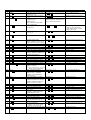
FEATURES AND FUNCTIONS
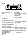
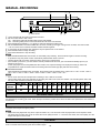
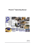
FRONT VIEW
2 1
3
4 5
POWER
REC
EJECT
STOP
S-VHS
OFF
ON
PICTURE
DISPLAY
SOFT
SHARP
POSITION/
TRACKING VERTICAL
ADJUST
I
J HG F
COUNTER
RESET
Fluorescent display
COUNTER MEMORY/
SKIP/INDEX
REC/PLAY
MODE
TIMER REC
6
JOG/ADJUST
SHUTTLE
CLEAR/
ENTER/
REW
FF
PLAY
PAUSE/
SHUTTLE HOLD
A
D
E C B 98
7
C REC/PLAY MODE buttons
Set to 3H, L12H, L24H, 48H - 960H or 0H mode to select
recording speed. Set to 3H, L12H, 12H, L24H, 24H, 48H
- 960H or 0H mode to select playback speed during
playback recorded in SP mode.
1 POWER button (Press for on; press again for off)
The POWER indicator illuminates when the VCR is
switched on.
2 EJECT button
Press to remove the cassette.
D COUNTER RESET button
Press to reset the counter to “00000”.
3 Cassette loading slot
Cassette tape is inserted in this slot for loading.
E DISPLAY button
Press to display the MAIN MENU.
Press again to show the present time display.
4 STOP button
Press to discontinue all tape related functions.
5 REC (RECORD) button
Press to begin recording.
F POSITION/VERTICAL ADJUST buttons
• When (+) button is pressed, the day and present time
display will move to the right. When the (-) button is
pressed, the day and present time will move down the
screen. Cannot be adjusted if a warning is displayed.
• Press these buttons to adjust for vertical vibrations when
in still mode or during fast playback. Refer to pages 7
and 27 for more details.
6 JOG dial
Use to forward the tape frame-by-frame and to set the
menus.
7 SHUTTLE ring
Use to adjust the playback speed or to set the menus.
Turn this ring to the right to forward a tape or to forward
search. Turn this ring to the left to rewind a tape or to
reverse search. Also use to clear the alarm list, power
loss list and timer recording and to initialize the menu
settings.
G TRACKING buttons (+/-)
Press these buttons if noise is present during playback,
reverse playback or slow playback.
H PICTURE control
The picture quality can be adjusted between soft and
sharp.
8 PLAY button
Press to playback a previously recorded tape.
I LOCK button
When pressed with a ball-point pen or a pencil, the unit
will be locked into the current mode and the operation
buttons will not operate. Release the lock by pressing
the lock button again.
9 PAUSE/SHUTTLE HOLD button
When pressed during recording, tape movement stops
temporarily. Press again to continue the recording.
When pressed during playback, tape movement stops
and a still field is displayed. Press again to restore normal
playback. Pressing and holding this button after turning
the SHUTTLE ring allows continuous high speed playback
even if the SHUTTLE ring is released.
J S-VHS switch
Used to select ON/OFF S-VHS mode while recording.
ON : Resumes S-VHS mode recording when using SVHS cassette.
OFF : Recording takes place in VHS mode with both
VHS and S-VHS cassette.
A COUNTER MEMORY/SKIP/INDEX button
Use to switch between COUNTER MEMORY (P.19), SKIP
SEARCH or INDEX SEARCH (P.24).
B TIMER REC button
This button is pressed when a timer recording is to be
made.
4
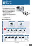
FLUORESCENT DISPLAY
1 2
3
4
5
M PL
ALARM
INDEX
MODE
67
8
9A
B
S VHS
SP
S
SKIP
EMGCY
H LOCK PLAY
H
G
1 M (COUNTER MEMORY) indicator
Illuminates during rewind for counter memory mode.
C
F
E
E
REC
D
9 Repeat indicator
Illuminates when “TAPE END” in the “FIRST TIME SET
UP” menu is set to “REPEAT” or “ALARM•PROT”.
2 PL (POWER LOSS) indicator
Illuminates when there is a power failure during recording.
A Cassette status indicator
Illuminates when cassette tape is inserted. The light
advances, stops or flashes corresponding to the
movement of the tape.
3 ALARM indicator
Flashes during alarm recording and stays on when the
alarm recording is finished.
B Timer recording indicator
Illuminates when the TIMER REC button is set to ON.
4 INDEX indicator
Flashes during recording of date/hour index signal at the
change of the hour, and during recording of the alarm
index signal. Lights during index search and the setting
of Index search.
C Tape remaining indicator
Indicates the approximate tape position. S=Start,
E=End.
D REC indicator
Illuminates during recording.
5 MODE display
Displays the selected recording or playback mode. During
index search, displays the index number. It will also
indicate the playback head selection, “SH” or “AH”, 3
seconds after the playback starts or if the playback mode
is changed. In the “FIRST TIME SET UP” menu, if the
“PB HEAD SELECT” is set to “L/L” or “R/R” then “SH” will
illuminate. If set to “AUTO”, then “AH” will illuminate.
E PLAY indicator
Illuminates during playback.
F EMGCY (EMERGENCY REC) indicator
Illuminates when “EMERGENCY REC” of the
“RECORDING SET UP” menu is set to “ON”.
6 SKIP indicator
Illuminates during skip search.
G LOCK indicator
Lights when the Lock mode is set.
7 Record mode indicator
SP illuminates to indicate recording in SP mode or playing
back a tape recorded in SP mode.
H COUNTER display
Indicates the relative position on the tape.
8 S-VHS indicator
This indicator illuminates when the VCR is playing back
a tape recorded in the S-VHS mode or when the S-VHS
switch is ON while recording.
5
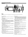
FEATURES AND FUNCTIONS
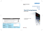
REAR VIEW
1
24 6
9 A
3 5 78
SET
RST
IN
REC GND ALM MODE
B
IN
RS-232C
CLK CALL
OUT
RESET
IN
IN
ÉMIC
OUT
AUDIO
IN
VIDEO
OUT
OUT
S-VIDEO
REMOTE
OUT
KJ I H
G
F ED
C
N
• Ensure the power cord is not plugged into the mains outlet before connecting to any rear terminals.
1 AC power socket
This socket connects to the power cord. Insert the cord
firmly.
A RESET button
When pressed, the present time, alarm recording list, power
loss list and the number of tape use will be erased. While
the button is pressed, the power is cut off from the VCR. If
there is a cassette tape in the VCR and the button is
released, the power indicator will light and the tape will fast
forward for a few seconds. The VCR will then switch off.
2 SET IN terminal
Input terminal for alarm recording. The alarm sensor is
connected here.
3 RST (RESET) IN terminal
Input terminal to stop alarm recording when “ALARM REC
DURATION” of the “RECORDING SET UP” menu is set
to “MAN1”. The alarm reset switch is connected here.
This terminal can also be used to set the on-screen clock
when set to any mode other than “MAN1”.
B RS-232C IN terminal (D-SUB 9pin)
Input terminal to connect with a personal computer via
RS-232C cross cable.
C RS-232C OUT terminal (D-SUB 9pin)
Output terminal to connect the VCR with other VCRs via
RS-232C cross cable.
4 REC IN terminal
Input terminal to start/stop recording. Also, use this
terminal for series recording (P.17) or synchronous
recording (P.18).
D S-VIDEO OUT connector
Output connector for video signal. (S-VIDEO connector)
E S-VIDEO IN connector
Input connector for video signal. (S-VIDEO connector)
5 GND (GROUND) terminal
When a lead connected to other terminals requires a
ground, connect the ground lead here.
F REMOTE jack
Remote control is possible by connecting the optional
remote control unit (R-7100) here. Refer to page 40.
6 ALM (ALARM) OUT terminal
Output terminal to indicate alarm recording to an external
alarm.
G VIDEO OUT connector
Output connector for video signal (BNC connector). If
the power switch is turned OFF, the signal from the VIDEO
IN connector is looped out to this connector.
7 MODE OUT terminal
Output terminal to indicate the VCR’s mode of operation.
Selected by setting “MODE OUT” on the “REAR
TERMINAL” menu.
H VIDEO IN connector
Input connector for video signal (BNC connector).
8 CLK (CLOCK) OUT terminal
Output terminal to control an external camera switcher.
I AUDIO OUT connector
Audio output connector (RCA pin).
9 CALL OUT terminal
Output terminal to indicate when tape has finished
recording or if there has been a problem during recording.
J AUDIO IN connector
Audio input connector (RCA pin).
K MIC IN jack
Input jack for a microphone with 600 ohms impedance.
6
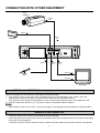
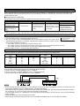
CONNECTING WITH OTHER EQUIPMENT
CCTV
CAMERA
VIDEO
OUT
SET IN
VIDEO
IN
SENSOR
SET
RST
IN
REC GND ALM MODE
IN
RS-232C
CLK CALL
OUT
RESET
IN
MIC
IN
OUT
AUDIO
IN
VIDEO
OUT
OUT
S-VIDEO
REMOTE
OUT
MIC IN
AUDIO
OUT
VIDEO
OUT
VIDEO IN
MIC
AUDIO IN
MONITOR
VERTICAL ADJUSTMENT (Correcting picture vibration at the top and bottom)
The picture vibration can be reduced or eliminated by the following steps.
1 If the vibration occurs in still, slow motion, fast playback (x2) or normal playback in 12H - 960H or 0H mode,
playback a tape which is recorded in 3H mode with this VCR and press the PAUSE button.
If the vibration occurs during normal playback in L12H or L24H mode, playback a tape in each playback mode.
2 Press the VERTICAL ADJUST (+) or (-) button to reduce or eliminate the picture vibration.
N
•
When QUASI V-SYNC is set to “OFF”, the picture vibration is not adjustable with the VERTICAL ADJUST buttons.
MONITOR TO BE CONNECTED
•
•
Connection with a CCTV monitor (for surveillance) is recommended.
Connecting with some monitors may cause picture vibration and/or picture distortion at the top or bottom of the image
during still or normal playback.
A domestic Television used as a Monitor may be unable to provide a stable picture without vibration and distortion.
7
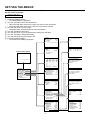
SETTING THE MENUS
The operating parameters of this VCR are set through various on-screen menus.
Set the menus as follows:
OPERATION
1 Press the DISPLAY button.
• The “MAIN MENU” is displayed.
2 Turn the JOG dial to select the desired item.
• When the JOG dial is turned to the right, the cursor moves downward.
• When the JOG dial is turned to the left, the cursor moves upward.
3 Turn the SHUTTLE ring to the right.
• The desired item is selected and the menu will appear.
4 Turn the JOG dial to select item.
5 Turn the SHUTTLE ring to the right and the setting item will flash.
6 Turn the JOG dial to change the setting.
7 Turn the SHUTTLE ring to the right to set.
<DISPLAY>
8 Press the DISPLAY button.
1
DISPLAY MODE
SMALL
TIME DATE SIZE
• The present time display will appear.
ON
BLUE BACK
<POWER LOSS LIST>
01 01 - 03 - 99 01 : 00
02
03
Ex.<MODE 1>
11 - 11 - 99 09 : 21 : 01
Present Time Display
<TIME DATE SEARCH>
15:00
TIME
23
DATE
FORWARD
DIRECTION
<ALARM LIST>
0001
01 - 05 - 99 01 : 00
0002
01 - 07 - 99 21 : 10
0003
01 - 10 - 99 09 : 15
Use JOG to adjust,
and ENTER.
<TIMER PROGRAM>
DW START END
HR
SPL 08 : 40 17 : 10 L12SP
2 SAT 08 : 40 12 : 20 L12SP
3 WED 22 : 00 22 : 54
3SP
4 --- --:-- --:-- --5 --- --:-- --:-- --6 --- --:-- --:-- --7 --- --:-- --:-- --8 --- --:-- --:-- --SPECIAL DW
MON–FRI
11 – 11 – 99 09 : 21 : 01
<MAIN MENU>
DISPLAY
TIME DATE SEARCH
TIMER PROGRAM
RECORDING SET UP
REAR TERMINAL
MAINTENANCE
FIRST TIME SET UP
Use JOG to select,
and ENTER.
Press DISPLAY to exit.
<RECORDING SET UP>
ALARM REC MODE
ALARM REC DURATION
EMERGENCY REC
ONESHOT•FIELD
ONESHOT•INTERVAL
ALL MENU INITIALIZE
Turn the SHUTTLE RING <<
then all MENU will be
initialized.
POWER LOSS LIST CLEAR
3H
1M
OFF
1
SHOT
Turn the SHUTTLE RING <<
then POWER LOSS LIST
will be cleared.
ALARM LIST CLEAR
<REAR TERMINAL>
WRNG•TAPE END
CALL OUT
REC- 1
CLOCK OUT
REC
MODE OUT
SERIES
REC IN
<TIME DATE ADJUST>
DAYLIGHT SAVINGS
OFF
DATE
11
MONTH
11
YEAR
99
TIME
09 :21 : 01
<MAINTENANCE>
POWER LOSS LIST
ALARM LIST
ALL MENU INITIALIZE
POWER LOSS LIST CLEAR
ALARM LIST CLEAR
<REPEAT REC TIMES>
<ELAPSED TIME>
0
0H
<FIRST TIME SET UP>
STOP
TAPE END
ON
QUASI V-SYNC
E-180
TAPE LENGTH
COLOUR
VIDEO MODE
NORMAL
PB HEAD SELECT
WRNG
BUZZER
TIME DATE ADJUST
RS-232C
8
Turn the SHUTTLE RING <<
then ALARM LIST will be
cleared.
<RS-232C>
TRANSMISSION RATE
DATA BIT LENGTH
STOP BIT LENGTH
PARITY BIT
DELIMITTER<SEND>
DELIMITTER<RECEIVE>
VCR ADDRESS
1200
8BIT
1BIT
NONE
CR
CR
NONE
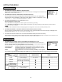
MAIN MENU
<MAIN MENU>
DISPLAY
TIME DATE SEARCH
TIMER PROGRAM
RECORDING SET UP
REAR TERMINAL
MAINTENANCE
FIRST TIME SET UP
Use JOG to select,
and ENTER.
Press DISPLAY to exit.
1
DISPLAY
Sets the display format of the date and present time on the monitor.
2
TIME DATE SEARCH
Sets the date, time and direction to search for the desired location on a tape.
3
TIMER PROGRAM
Sets the timer recording.
4
RECORDING SET UP
Sets the alarm recording mode, alarm recording duration, emergency recording, recording mode and one-shot recording.
5
REAR TERMINAL
Sets the frequency division ratio of CLOCK OUT, output signal of the CALL OUT terminal and the MODE OUT terminal, etc.
6
MAINTENANCE
Displays the power loss list and alarm loss list, etc. and initialises all menu settings. Clears the power loss list and alarm list.
7
FIRST TIME SET UP
Set up for when the end of the tape is reached, quasi v-sync, tape length, playback head selection, buzzer setting and present time.
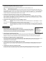
DISPLAY
1
<DISPLAY>
SETTING THE DISPLAY MODE (DISPLAY MODE)
1
DISPLAY MODE
DISPLAY MODE 1:
Displays date and present time. (Refer to page 13.)
SMALL
TIME DATE SIZE
ON
BLUE BACK
DISPLAY MODE 2:
Displays date, day of the week, present time and recording mode. (Refer to
page 13.)
Ex.<MODE 1>
11 – 11 – 99 09 : 21 : 01
DISPLAY MODE 3:
Displays nothing; until an alarm recording starts, then date, alarm recording
number, etc. is displayed.
DISPLAY MODE 4:
Displays nothing; even in the case of alarm recording, nothing is displayed
on the monitor.
• During an alarm recording, alarm recording number is displayed if the “DISPLAY MODE” is set from 1 to 3.
2
SETTING THE SIZE OF THE LETTERS OF DAY AND PRESENT TIME DISPLAY (TIME DATE SIZE)
SMALL: The size of the letters becomes small.
LARGE: The size of the letters becomes large.
3
SETTING THE BACKGROUND COLOUR (BLUE BACK)
ON:
The blue screen overlays on the recorded picture when menu is displayed on the monitor.
OFF:
The blue screen will be replaced by the recorded picture overlaid with the menu display.
N
• The above setting will also affect the background colour when there is no recording input signal. When BLUE BACK is set to
“ON”, the warning, “NO SIGNAL” appears on the blue screen and when set to “OFF”, the blue screen or warning does not
appear on the monitor.
TIME DATE SEARCH
Sets the date, time and direction to search for the desired location on a tape.
<TIME DATE SEARCH>
15:00
TIME
23
DATE
FORWARD
DIRECTION
1
SETTING THE TIME
Turn the JOG dial to set the hour and minute to search for.
2
SETTING THE DATE
Turn the JOG dial to set the day of the month to search for.
3
SETTING THE DIRECTION
Turn the JOG dial to select the starting direction for search.
FORWARD:
Search in the forward direction.
REVERSE:
Search in the reverse direction.
• If the desired part of a tape is not found in one direction, the VCR automatically searches in the opposite direction.
Use JOG to adjust,
and ENTER.
After the setting, turn the SHUTTLE ring to the right to start searching.
N
• An hour index mark is written on the tape on the hour and is used as a reference in the search function. Because of this, a
recorded tape must pass a time clock hour mark before this function can work. The TIME DATE SEARCH function begins after
the first hour index mark.
Example 1: VCR is set to record from 8:30 to 17:30 - Times from 9:00 to 17:30 can be found.
Example 2: VCR is set to record in one speed from 7:00 to 14:30, then in another speed until 18:00.
- Times from 7:00 to 14:30 and 15:00 to 18:00 are accurately located.
• Time date search function is not available for a tape recorded by any other VCR than this model.
• If recording quality is poor, the VCR may fail to locate the desired part of the tape during time date search.
TIMER PROGRAM
Refer to page 20, “TIMER RECORDING” for details.
9
SETTING THE MENUS
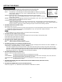
RECORDING SET UP
1
SETTING THE ALARM REC MODE (ALARM REC MODE)
Sets the alarm recording time mode. When the JOG dial is turned, the display will be switched in the
order of 3H } L12H } L24H } 3H } ....
2
SETTING THE ALARM REC DURATION (ALARM REC DURATION)
<RECORDING SET UP>
ALARM REC MODE
ALARM REC DURATION
EMERGENCY REC
ONESHOT•FIELD
ONESHOT•INTERVAL
3H
1M
OFF
1
SHOT
Sets the duration of the alarm recording period. When the JOG dial is turned, the display will be
switched in the order of 1M(minute) } 2M } 5M } 10M } MAN1 } MAN2 } 15S(second) } 30S
} 45S } 1M } .... Refer to “ALARM RECORDING” on page 22.
3
SETTING THE EMERGENCY REC (EMERGENCY REC)
Sets the emergency recording mode.
OFF: Starts alarm recording when the alarm signal is received during recording.
ON: Starts alarm recording when the alarm signal is received not only during recording but also when the power is OFF or
when the tape is stopped.
N
• When “ON” is selected, the alarm recording begins even though the recorder is in recording standby mode.
4
SETTING THE NUMBER OF FIELDS IN ONE-SHOT RECORDING (ONE SHOT•FIELD)
Sets the number of recorded fields in the one-shot recording mode. When the JOG dial is turned to the right, the display will be
switched in the order of 1 } 2 } 3 } 4 } 5 } 10 } 20 } 30 } 1 }....
5
SETTING THE INTERVAL TIME IN THE ONE-SHOT RECORDING MODE (ONE SHOT•INTERVAL)
Sets the interval time in the one-shot recording mode. When the JOG dial is turned to the right, the display will be switched in the
order of SHOT } 10S (second) } 15S } 30S } 45S } 1M } 2M } 3M } SHOT }....
REAR TERMINAL
1
SETTING THE CALL SIGNAL OUTPUT AT THE END OF THE TAPE (CALL OUT)
Enables or disables the signal that is output from the CALL terminal when the end of the tape is
reached during recording. If any abnormalities occur during recording, a CALL signal is output from
the CALL terminal on the rear panel regardless of CALL OUT setting.
WRNG•TAPE END:
WRNG•REMAIN:
WRNG:
<REAR TERMINAL>
WRNG•TAPE END
CALL OUT
REC- 1
CLOCK OUT
REC
MODE OUT
SERIES
REC IN
A signal is output at the end of the tape or when a malfunction occurs.
The signal is output when a malfunction occurs in this VCR or when the
tape has approximately 3 minutes left in 3H mode.
When a malfunction occurs in the VCR during recording, a CALL signal is
output.
This is used in conjunction with TAPE END (FIRST TIME SET UP) to determine when the CALL signal is output as shown below.
CALL OUT
TAPE END
setting
setting
WRNG•TAPE END
STOP
Outputs a call signal at the
end of the tape
REWIND
Outputs a call signal at the
end of the tape for 2 seconds
WRNG•REMAIN
Outputs 3 minutes before When a malfunction occurs in the VCR
during recording, a call signal is output.
the tape end
REPEAT
ALARM
• PROT
WRNG
When there are no
alarm recordings
during recording
When there are alarm Outputs a call signal at the
recordings during
end of the tape
recording
10
2
SETTING THE FREQUENCY DIVISION RATIO (CLOCK OUT)
Sets the frequency division ratio of the CLOCK OUT terminal.
First, set the recording mode for the “CLOCK OUT” pulse output in the “REAR TERMINAL” menu.
REC:
T/L-REC:
When recording in any mode.
When recording in time lapse mode (L12H, L24H, 48H, 72H, 96H, 120H, 168H, 240H, 360H, 480H, 720H, 960H or 0H).
Second, select the frequency division ratio setting by turning the SHUTTLE ring. When the JOG dial is turned, the display will be
switched in the order of 1 } 2 } 3 } 4 } 5 } 10 } 15 } 20 } 25 } 30 } 50 } 60 } F (field) } 1 } ... The numbers from 1
to 60 indicate the number of frames in 3H recording mode or the number of fields in time lapse recording mode. (One frame
consists of two fields.) One field is selected when it is set to “F” (field).
3
SETTING THE OPERATION MODE OF THE MODE OUTPUT TERMINAL (MODE OUT)
Set the state in which the signal output at the MODE OUT terminal is switched to the active condition. When the JOG dial is
turned, the display will be switched on in the order of REC(recording) } PLAY(playback) } POWER (power “ON”) } TAPE IN
(tape is inserted) } TAPE REMAIN (3 minutes in 3H mode before the tape end) } CLOCK ADJ (output the signal for 1 second
when the clock indicates “00(min.):00(sec.)”) } REC
4
SETTING THE OPERATION MODE OF THE REC IN TERMINAL (REC IN)
SERIES:
Recording starts when the REC IN terminal is short-circuited to ground or a “L” level voltage (0 - +1.6V) is
applied.
REC-START/ STOP: Recording starts when the REC IN terminal is short-circuited to ground or a “L” level voltage (0 - +1.6V) is
applied. Should this connection be removed, recording will stop.
SYNC REC:
The video signal from 5 or 9 cameras can be recorded separately by connecting a switcher. (“SYNC REC”
function is available when recording in L12H or L24H mode.) Refer to “SYNCHRONOUS RECORDING” on
page 18.
MAINTENANCE
1
DISPLAYING THE POWER LOSS LIST (POWER LOSS LIST)
Turn the JOG dial to select “POWER LOSS LIST”. Turn the SHUTTLE ring to the right to display the
Power Loss List. Power failure start times are stored in memory, so it is possible to confirm when
they have occurred. Up to 3 power failure start times will be displayed. If more than 3 failures have
occurred, the first and last 2 power failure start times will be displayed.
2
<MAINTENANCE>
POWER LOSS LIST
ALARM LIST
ALL MENU INITIALIZE
POWER LOSS LIST CLEAR
ALARM LIST CLEAR
<REPEAT REC TIMES>
<ELAPSED TIME>
0
0H
DISPLAYING THE ALARM LIST (ALARM LIST)
Turn the JOG dial to select “ALARM LIST”. Turn the SHUTTLE ring to the right to display the Alarm List. Alarm record start
times are stored in memory, so it is possible to confirm when they have occurred. Up to 3 alarm record start times will be
displayed. If more than 3 alarm records have occurred, the first and the last 2 alarm record start times will be displayed.
3
INITIALIZING ALL MENU SETTINGS (ALL MENU INITIALIZE)
Turn the SHUTTLE ring to the right and “ALL MENU INITIALIZE” will be displayed. When the SHUTTLE ring is turned to the left,
each setting is initialised except the TIMER RECORDING setting. When the SHUTTLE ring is turned to the right, the
“MAINTENANCE” menu will be displayed.
4
CLEARING THE POWER LOSS LIST (POWER LOSS LIST CLEAR)
Turn the SHUTTLE ring to the right and “POWER LOSS LIST CLEAR” will be displayed. When the SHUTTLE ring is turned to
the left, the Power Loss List is cleared. When the SHUTTLE ring is turned to the right, the “MAINTENANCE” menu will be
displayed.
5
CLEARING THE ALARM LIST (ALARM LIST CLEAR)
Turn the SHUTTLE ring to the right and “ALARM LIST CLEAR” will be displayed. When the SHUTTLE ring is turned to the left,
the alarm list is cleared. When the SHUTTLE ring is turned to the right, the “MAINTENANCE” menu will be displayed.
11
SETTING THE MENUS
FIRST TIME SET UP
1
SETTING THE OPERATION WHEN THE TAPE REACHES THE END (TAPE END)
Sets the state of operation of the VCR when the tape runs out during recording.
STOP:
<FIRST TIME SET UP>
STOP
TAPE END
ON
QUASI V-SYNC
E-180
TAPE LENGTH
COLOUR
VIDEO MODE
NORMAL
PB HEAD SELECT
WRNG
BUZZER
TIME DATE ADJUST
RS-232C
The tape stops. “End” will appear on the fluorescent display and “Tape End” will appear
on the monitor. When “CALL OUT” is set to “WRNG•TAPE END”, a CALL signal is output
from the CALL terminal.
REWIND: Rewinds the tape to the beginning and stops (except during timer recording.)
When “CALL OUT” is set to “WRNG•TAPE END”, a CALL signal is output for 2 seconds
from the CALL terminal.
REPEAT: Rewinds the tape to the beginning and resumes recording.When “CALL OUT” is set to “WRNG•TAPE END”, a CALL
signal is output for 2 seconds from the CALL terminal.
ALARM•PROT(ALARM PROTECTION):
If alarm recordings are present on the tape, then the tape stops. “End” will appear on the fluorescent display and
“Tape End” will appear on the monitor. When “CALL OUT” is set to “WRNG•TAPE END”, a CALL signal is output from
the CALL terminal. If there are no alarm recordings, the tape is rewound and recording continues.
2
SETTING QUASI-V-SYNC (QUASI V-SYNC)
Sets Quasi-V-Sync on or off.
ON: Quasi-V-Sync signal is inserted on the video output signal when in the special playback modes (still, slow motion, reverse,
fast playback, speed search) and during normal playback in L12H, 12H, L24H, 24H - 960H or 0H mode.
OFF: Quasi-V-Sync signal is not inserted.
N
• Some multiplexers may require the Quasi-V-sync OFF in order to work properly.
3
SETTING THE TAPE LENGTH (TAPE LENGTH)
For the tape indicator to operate correctly the tape length must be set according to the tape being used.
E-180: When using E-180 tape or SE-180 tape.
E-240: When using E-240 tape or SE-240 tape.
4
SETTING THE VIDEO MODE (VIDEO MODE)
COLOUR: Select for colour recording or playback.
B/W:
Select for black and white recording or playback.
5
SETTING THE HEADS FOR PLAYBACK (PB HEAD SELECT)
Sets the heads for playback. When the JOG dial is turned to the right, the display will be switched in the order of NORMAL } L/
L(LEFT/LEFT) } R/R (RIGHT/RIGHT) } AUTO } NORMAL } ...
•
6
This VCR is equpped with two pairs of SP heads. Some VCRs make Time Lapse recordings using same Azimuth heads
which are not VHS compatible. Playback of such tapes with the Normal setting will have picture/noise with a 25 Hz flicker, or
just noise. To obtain proper playback, adjust the setting to AUTO, or set to L/L or R/R. One setting will provide normal play.
After playing a tape with L/L or R/R settings, return the setting to NORMAL.
SETTING THE BUZZER ON/OFF (BUZZER)
Sets the conditions for which the buzzer sounds.
WRNG:
WRNG•REMAIN:
The buzzer sounds when there is any malfunction in the VCR.
The buzzer sounds when there is any malfunction in the VCR or when the tape (E-180, E-240, SE-180 or
SE-240) has approximately 3 minutes left in 3H mode.
WRNG•TAPE END: The buzzer sounds when there is any malfunction in the VCR or at the tape end.
OFF:
The buzzer does not sound.
7
SETTING THE PRESENT TIME, DATE AND DAYLIGHT SAVING TIME SETTINGS (TIME DATE ADJUST)
Refer to the pages 13 - 14.
8
SETTING THE PARAMETER OF RS-232C SETTING (RS-232C)
Reref to the pages 28 - 36, “USING WITH THE PERSONAL COMPUTER” for details.
12
SETTING THE PRESENT TIME
ACCURATELY PRESET THE DAY AND PRESENT TIME BEFORE TIMER PROGRAMMING
<Display mode 1>
1 Day-Month-Year
2 Hour:Minute:Second
3 Daylight saving time symbol or power failure symbol
4 Alarm recording number
2
1
3
01-01-99 00:00:00
4
A0001
• A 24-hour display is used. 00:00 indicates midnight; 12:00 midday and 15:00
indicates 3 o’clock in the afternoon.
• An alarm recording number is shown during alarm recording.
<Display mode 2>
1 Day-Month-Year
2 Day of the week
3 Alarm recording number
4 Hour:Minute:Second
5 Daylight saving time symbol or power failure symbol
6 Recording mode
• A 24-hour display is used. 00:00 indicates midnight; 12:00 midday and 15:00
indicates 3 o’clock in the afternoon.
• The day of the week is automatically set.
• An alarm recording number is shown during alarm recording.
1 Press the DISPLAY button to display MAIN MENU on the monitor.
1
2
3
01-01-99
FRI
A0001
00:00:00
L12
4
5
6
<MAIN MENU>
DISPLAY
TIME DATE SEARCH
TIMER PROGRAM
RECORDING SET UP
REAR TERMINAL
MAINTENANCE
FIRST TIME SET UP
Use JOG to select,
and ENTER.
Press DISPLAY to exit.
<MAIN MENU>
DISPLAY
TIME DATE SEARCH
TIMER PROGRAM
RECORDING SET UP
REAR TERMINAL
MAINTENANCE
FIRST TIME SET UP
Use JOG to select,
and ENTER.
Press DISPLAY to exit.
2 Turn the JOG dial to select “FIRST TIME SET UP”.
3 Turn the SHUTTLE ring to the right .
• “FIRST TIME SET UP” setting menu will appear.
<FIRST TIME SET UP>
STOP
TAPE END
ON
QUASI V-SYNC
E-180
TAPE LENGTH
COLOUR
VIDEO MODE
NORMAL
PB HEAD SELECT
WRNG
BUZZER
TIME DATE ADJUST
RS-232C
4 Turn the JOG dial to select “TIME DATE ADJUST”.
<FIRST TIME SET UP>
STOP
TAPE END
ON
QUASI V-SYNC
E-180
TAPE LENGTH
COLOUR
VIDEO MODE
NORMAL
PB HEAD SELECT
WRNG
BUZZER
TIME DATE ADJUST
RS-232C
<TIME DATE ADJUST>
DAYLIGHT SAVINGS
OFF
MONTH
01
DATE
01
YEAR
99
TIME
00 :00 : 00
5 Turn the SHUTTLE ring to the right .
• “TIME DATE ADJUST” setting menu will appear.
13
SETTING THE PRESENT TIME
6 Setting the daylight saving time
To put the clock forward by 1 hour, set DAYLIGHT SAVINGS to ON.
Turn the JOG dial to select “OFF” or “ON”.
• The clock is put forward by 1 hour and the daylight saving time symbol “ ” will
be displayed next to the present time display .
• To cancel daylight saving time, switch “DAYLIGHT SAVINGS” to “OFF”.
<TIME DATE ADJUST>
DAYLIGHT SAVINGS
OFF
MONTH
01
DATE
01
YEAR
99
TIME
00 :00 : 00
N
• Should a power failure occur while daylight saving time is selected, the power
failure mark “X” will replace the daylight saving time symbol. When the power
failure mark “X” disappears, the daylight saving time symbol “ ” will reappear.
7 Setting the month
Turn the SHUTTLE ring to the right. The month display will flash.
Turn the JOG dial to set the “MONTH”.
8 Setting the date
Turn the SHUTTLE ring to the right. The date display will flash.
Turn the JOG dial to set the “DATE”.
<TIME DATE ADJUST>
DAYLIGHT SAVINGS
OFF
MONTH
01
DATE
01
YEAR
99
TIME
00 :00 : 00
<TIME DATE ADJUST>
DAYLIGHT SAVINGS
OFF
MONTH
02
DATE
01
YEAR
99
TIME
00 :00 : 00
9 Setting the year
Turn the SHUTTLE ring to the right. The year display will flash.
Turn the JOG dial to set the “YEAR”.
• The year digits can be set to 99 (for year 1999) - 29 (for year 2029).
<TIME DATE ADJUST>
DAYLIGHT SAVINGS
OFF
MONTH
02
DATE
05
YEAR
99
TIME
00 :00 : 00
A Setting the present time
Turn the SHUTTLE ring to the right. The hour digits of “TIME” display will flash.
Turn the JOG dial to set the hour digits of the present time.
• Set the 10 minutes digit and 1 minute digit in a similar fashion.
<TIME DATE ADJUST>
DAYLIGHT SAVINGS
OFF
MONTH
02
DATE
05
YEAR
99
TIME
00 :00 : 00
B Turn the SHUTTLE ring to the right.
Setting is now complete.
C Press the DISPLAY button.
The present time display will appear.
N
• The POWER button will not operate if any of the menu displays are flashing.
2 SETTING THE PRESENT TIME TO THE EXACT SECOND
Set the 10 minutes digit and 1 minute digit as described above, then 1 minute digit flashes and the second digit stays
at “00”. Turn the SHUTTLE ring to the right when the Time Signal reaches 00 second of the time you have set. The
present time will start counting from 00 second.
14
LOADING AND UNLOADING THE CASSETTE TAPE
Video cassette tapes can be loaded into your new VCR as long as the VCR is plugged into a power source. Even if the VCR power
switch is turned off, loading a cassette will automatically cause it to turn on. Use only video cassette tapes marked V or S.
Do not use a E-240 or SE-240 cassette tape when recording in 48H - 960H or 0H mode.
LOADING
1 To position the cassette properly before inserting it in the cassette slot, hold
the cassette so that the long narrow edge with the contents label faces towards
you. The other long narrow edge is hinged and should face towards the VCR.
The clear plastic window that shows the video tape should face upward.
2 Gently insert the videotape into the cassette slot to a point where the VCR
automatically retracts the cassette.
• When you insert the videotape, be sure to align it squarely to the slot.
POWER
REC
EJECT
STOP
VIDEO
COLOR
B/W
PICTURE
DISPLAY
SOFT
SHARP
POSITION/
TRACKING VERTICAL
ADJUST
COUNTER
RESET
COUNTER MEMORY
SKIP/INDEX
REC/PLAY
MODE
TIMER REC
JOG/ADJUST
CLEAR
REW
PLAY
PAUSE/
SHUTTLE HOLD
CORRECT
N
• Your new VCR has a protection circuit which will eject the tape if it is loaded
improperly. If the VCR ejects the tape you are trying to load, remove it
completely and check that the long narrow edge with the contents label is
facing towards you and that the clear plastic window that shows the video
tape is facing upwards. Then try again.
UNLOADING
1 Press the EJECT button on the front of the VCR.
INCORRECT
2 Remove the cassette.
N
• Your VCR will eject a video cassette even if it is in STANDBY mode. When
the EJECT button is pressed, the VCR will automatically turn on, eject the
tape and turn off. It is not possible to eject a tape whilst recording without first
pressing the STOP button. A tape cannot be ejected when the VCR is locked.
PREVENTING ACCIDENTAL ERASURE
Video cassettes come with an erasure prevention tab which, when removed,
prevents the tape’s contents from being erased or recorded over. A cassette
without the erasure prevention tab will automatically be ejected from your VCR if
you attempt to record on it.
N
• We recommend that any torn or broken cassette tape requiring repair should
only be taken to professionals who specialise in such procedures. The
adhesives on many common types of tape could damage the head of your
VCR.
15
SHUTTLE/ENTER
ENTER
FF
MANUAL RECORDING
7 6
1
POWER
REC
EJECT
STOP
S-VHS
OFF
ON
PICTURE
COUNTER MEMORY/
SKIP/INDEX
DISPLAY
SOFT
SHARP
POSITION/
TRACKING VERTICAL
ADJUST
COUNTER
RESET
2 LOCK button
REC/PLAY
MODE
TIMER REC
JOG/ADJUST
SHUTTLE
CLEAR/
ENTER/
REW
FF
PLAY
PAUSE/
SHUTTLE HOLD
4 3
1 Load a cassette with the erasure prevention tab intact.
2 Set the S-VHS switch to ON or OFF.
ON : Resumes S-VHS mode recording when using S-VHS cassette.
OFF : Recording takes place in VHS mode with both VHS and S-VHS cassette.
3 Press the REC/PLAY MODE (-) or (+) button to select the desired recording mode.
4 Set the VIDEO MODE in the FIRST TIME SET UP menu according to the type of image to be recorded, COLOUR or B/W.
• Do not connect colour cameras and black & white cameras together.
5 To record the day and present time, display the day and present time on the monitor.
6 Press the REC button to begin recording.
7 Press the STOP button to stop recording.
N
• Press the PAUSE/SHUTTLE HOLD button to momentarily stop recording. Press the button again to resume recording.
• To protect the tape, the pause mode is automatically released after about 5 minutes.
• The REC button will not function unless the tape is in the stop or pause mode.
• If the cassette you insert in your VCR has the erasure prevention tab removed, your VCR will automatically eject it if you
attempt to record on it.
• 3-Hour (SP) tapes are VHS compatible with other VCRs. Time Lapse recordings can be played correctly by other VHS
compatible Time Lapse Recorders when the recording interval and head type (SP) matches the recording.
2 RECORDING MODE
When the REC/PLAY MODE button is pressed, the recording mode is switched in the order of 3H } L12H } L24H } 48H }
72H } 96H } 120H } 168H } 240H } 360H } 480H } 720H } 960H } 0H } 3H ....
N
• Do not use an E-240 or SE-240 tape when recording in 48H - 960H or 0H modes.
• The recording mode of this VCR indicates the recording time with E-180 or SE-180 cassette. The recording times with E-180,
SE-180, E-240 and SE-240 cassette are as follows :
REC MODE
E-180
SE-180
E-240
SE-240
3H L12H L24H 48H 72H
96H 120H 168H 240H 360H 480H 720H 960H
SP
3
15
27
51
75
99
123
171
243
363
483
723
963
SP
4
20
36
X
X
X
X
X
X
X
X
X
X
RECORDING CHECK FUNCTION
When the VCR is recording, press the PLAY button for more than 1.5 seconds and then release. The tape will be rewound a little and
then playback the recording just made. When the tape reaches the position where the PLAY button was pressed, the VCR returns to
record mode.
AUDIO RECORDING
Either apply the specified line input signal to the AUDIO IN connector or connect the microphone to the MIC IN jack. If both are
connected, the microphone is given priority.
N
• Normal sound is played back only when a tape recorded in 3H, L12H and L24H mode is played back in their respective mode.
• The longer the recording time mode, the worse the sound quality becomes. In L12H and L24H mode, the sound quality is of the
degree that speech can be heard.
LOCK MODE
When the lock button is pressed with a ballpoint pen or a pencil, the control buttons will not operate and the VCR is kept in the current
mode. To release the lock mode, press the lock button again.
16
REPEAT RECORDING
When the “TAPE END” of the “FIRST TIME SET UP” menu is set to “REPEAT” or “ALARM•PROT” and the repeat recording mode is
set (the REPEAT indicator is illuminated), the tape will automatically be rewound to the start when the tape end is reached. Then
recording will start again.
2 WHEN TAPE END IS REACHED
The following functions are automatically engaged when the tape ends during recording :
STOP
When there are alarm
recordings on tape.
REPEAT
REWIND
The tape stops.
When there are no
alarm recordings on
tape.
ALARM•PROT
The tape is rewound
automatically to the
beginning and recording
is resumed.
The tape is rewound
automatically to the
beginning and then
stops.
The tape stops.
The tape is rewound
automatically to the
beginning and then the
recording is resumed.
N
• On “ALARM•PROT” mode, a tape with alarm recordings can be used for repeat recording if the tape is ejected and re-inserted.
THE NUMBER OF TAPE USE (REPEAT REC TIMES)
Displays the number of tape use when the TAPE END setting is set to “REWIND”, “REPEAT” or “ALARM• PROT”.
1. Press the DISPLAY button. MAIN MENU display will appear.
<REPEAT REC TIMES>
<ELAPSED TIME>
2. Turn the jog dial to select “MAINTENANCE” and turn the SHUTTLE ring to the right to enter.
“MAINTENANCE” will appear on the display. “REPEAT REC TIMES” indicates the number of times a
tape has been repeatedly recorded on.
• The number of tape use counts up by one when the tape ends.
• The number of tape use is memorised even if the mains supply is removed, provided the backup is active.
• The number of tape use is reset when the current tape is replaced with another.
3. Press the DISPLAY button. The present time will be displayed.
0
0H
RECOMMENDED NUMBER OF TAPE USE
Video tape becomes worn during use. A new cassette should be utilised according to the following chart.
Recording time
mode
Number of tape use
E-180/SE-180 cassette E-240/SE-240 cassette
3H
L12H
L24H
48H
72H, 96H
100
60
35
20
15
Recording time
mode
Number of tape use
E-180/SE-180 cassette E-240/SE-240 cassette
120H
168H
240H
360H, 480H
720H, 960H
50
30
17
–
–
10
8
6
4
2
–
–
–
–
–
SERIES RECORDING
Series recording is possible if two or more of these units are connected together. When the tape in the first VCR reaches the end
during recording, the tape in the second VCR automatically begins recording.
1. Set the “REC IN” of “REAR TERMINAL” menu to “SERIES”.
2. Set the “CALL OUT” of “REAR TERMINAL” menu to “WRNG•TAPE END”.
3. Set the “TAPE END” of “FIRST TIME SET UP” menu to “REWIND”.
[*1]
SET
RST
IN
REC GND ALM MODE
CLK
CALL
SET
OUT
1st VCR
RST
IN
REC GND ALM MODE
CLK
CALL
OUT
2nd VCR
N
• Series recording may have a short pause (≈ 5 seconds) when going from recorder A to recorder B. However, if you set the CALL OUT
of the “REAR TERMINAL” menu to “WRNG•REMAIN”, this delay is eliminated.
• When set in the above configuration and the second VCR reaches the end of the tape, the first VCR automatically begins recording.
Do not connect [*1], if you do not require the first VCR to begin recording again.
• If an abnormality occurs (e.g., a malfunction occurs in the motor during recording) in the first VCR, the second VCR automatically
begins recording.
• Series recording will not function during timer recording.
• When carrying out series recording, set “CALL OUT” in the “REAR TERMINAL” menu to a mode other than “WRNG”.
17
MANUAL RECORDING
ONE SHOT/INTERVAL RECORDING
One-shot recording or Interval recording is possible when the recording mode is set to 0H.
1 Press the REC/PLAY MODE button to set the recording mode to 0H.
2 Set the number of fields in “ONE SHOT•FIELD” on the “RECORDING SET UP” menu.
3 For One-shot recording, select “SHOT” in “ONE SHOT•INTERVAL”.
For Interval recording, choose the interval time from 10S(second) to 3M(minute) in “ONE SHOT•INTERVAL”.
4 Press the REC button.
• One-shot recording will be on STANDBY mode. Interval recording begins recording with the preset interval time.
5 To start One-shot recording, press the REC button or switch the REC IN terminal on the rear panel to ground.
SYNCHRONOUS RECORDING
A number of camera images can be mixed together through a camera switcher and then recorded separately onto several
VCRs. A camera is assigned to each VCR with the VCR recording only the camera image it has been assigned. This
allows recording without gaps.
If you have three VCRs, the video signal from three cameras can be recorded separately by connecting the switcher as shown below.
V-SYNC
SWITCHER/ switching cameras
CAMERA1 CAMERA2 CAMERA3 CAMERA4 CAMERA5 CAMERA1 CAMERA2 CAMERA3 CAMERA4 CAMERA5
/ recording start signal
VCR 1
/ recording
VCR 2
/ clock out
/ recording
VCR 3
/ clock out
/ recording
VCR 4
/ clock out
/ recording
REC
REC
REC
REC
REC
REC
REC
REC
/ clock out
VCR 5
/ recording
/ clock out
REC
REC
VIDEO IN
Connection:
CAMERA 1
VCR1
VIDEO
B/W
CLK OUT
SHUTTLE
CLEAR/
ENTER/
REW
FF
STOP
EJECT
COLOR
JOG/ADJUST
REC
POWER
PICTURE
DISPLAY
SOFT
SHARP
POSITION/
TRACKING VERTICAL
ADJUST
COUNTER
RESET
POWER
CAMERA 2
COUNTER MEMORY/
SKIP/INDEX
REC/PLAY
MODE
TIMER REC
PLAY
PAUSE/
SHUTTLE HOLD
REC IN
CLK OUT
VCR2
SWITCHER
EJECT
CAMERA 3
VIDEO
COLOR
B/W
JOG/ADJUST
REC
POWER
SHUTTLE
CLEAR/
ENTER/
REW
FF
STOP
PICTURE
DISPLAY
SOFT
SHARP
POSITION/
TRACKING VERTICAL
ADJUST
COUNTER
RESET
COUNTER MEMORY/
SKIP/INDEX
REC/PLAY
MODE
TIMER REC
PLAY
PAUSE/
SHUTTLE HOLD
REC IN
CLK OUT
VCR3
CAMERA 4
VIDEO
COLOR
B/W
SHUTTLE
CLEAR/
ENTER/
REW
FF
STOP
EJECT
CAMERA 5
JOG/ADJUST
REC
POWER
PICTURE
DISPLAY
SOFT
SHARP
POSITION/
TRACKING VERTICAL
ADJUST
COUNTER
RESET
COUNTER MEMORY/
SKIP/INDEX
REC/PLAY
MODE
TIMER REC
PLAY
PAUSE/
SHUTTLE HOLD
REC IN
CLK OUT
VCR4
CAMERAS
EJECT
VIDEO
B/W
JOG/ADJUST
REC
POWER
COLOR
SHUTTLE
CLEAR/
ENTER/
REW
FF
STOP
PICTURE
DISPLAY
SOFT
SHARP
POSITION/
TRACKING VERTICAL
ADJUST
COUNTER
RESET
COUNTER MEMORY/
SKIP/INDEX
REC/PLAY
MODE
TIMER REC
PLAY
PAUSE/
SHUTTLE HOLD
REC IN
VCR5
EJECT
VIDEO
COLOR
B/W
JOG/ADJUST
REC
POWER
SHUTTLE
CLEAR/
ENTER/
REW
FF
STOP
PICTURE
DISPLAY
SOFT
SHARP
POSITION/
TRACKING VERTICAL
ADJUST
COUNTER
RESET
COUNTER MEMORY/
SKIP/INDEX
REC/PLAY
MODE
TIMER REC
PLAY
PAUSE/
SHUTTLE HOLD
Set the “REC IN” of “REAR TERMINAL” menu to “SERIES” or “REC-START/STOP” on VCR1.
Set the “CLOCK OUT” of “REAR TERMINAL” menu to “T/L-REC” and “F” on VCR1.
Set the “REC IN” of “REAR TERMINAL” menu to “SYNC REC” on all VCRs except VCR1.
• If recording start signal is available on switcher, set the “REC IN” of the “REAR TERMINAL” menu to “SYNC REC” on
VCR1. Then, VCR1 will always record the picture from CAMERA1.
•
•
You must set the recording mode to L12H or L24H mode.
The suitable numbers of VCRs and cameras are shown in the table.
Recording mode VCR
L12H
L24H
5
9
Camera
Multiple of 5
Multiple of 9
18
ADDITIONAL FEATURES
COUNTER MEMORY
Press the COUNTER MEMORY/SKIP/INDEX button repeatedly until the “M” indicator appears on the fluorescent display.
Turn the SHUTTLE ring to the right and the tape will rewind to the “00000” position of the counter and stop. (The rewind to “00000” is
slightly inaccurate.)
N
• The counter display is stored in the memory when the power is turned off, so the same numbers will be displayed when the
power is turned back on.
TAPE COUNTER
A five digit counter indicates the relative position on the recorded portion of the tape. If a portion of the
tape is not recorded, the counter will not increase or decrease during play, FF/RWD or search modes.
•
“EEE EE” illuminates to indicate that the VCR power is in stand-by mode.
COUNTER RESET
Press the COUNTER RESET button to reset the counter to “00000”.
MEMORY BACK-UP IN CASE OF POWER FAILURE
This VCR includes a built-in memory back-up so the presets of present time and date, alarm list, power loss list and the number of
tape use will remain in memory if there is a power failure or if the POWER CORD is disconnected from the mains outlet. The presets
will remain in memory for a maximum of 31days provided that the VCR has been connected to the mains supply for at least 40 hours
per week. Connection charges the backup supply.
• Check the present time if there has been a power failure or if the POWER CORD has been disconnected from the mains for a
prolonged time.
RECORDING AFTER A POWER FAILURE
If there is a power failure during recording and the power comes back on, the VCR will begin
recording in the same record mode as before the power failure. After the power comes back on,
“X” will be displayed next to the present time for about 1 minute.
If a power failure occurs during playback, the VCR will be in the stop mode when the power
comes back on.
01-01-99
FRI
00:00:00X
L12
POWER FAILURE TIME DISPLAY
The power failure start time on recording is stored in the memory, so it is possible to confirm the start time.
1. Press the DISPLAY button to display the MAIN MENU.
<POWER LOSS LIST>
2. Turn the JOG dial to select “MAINTENANCE” and turn the SHUTTLE ring to the right.
01 03 - 01 - 99 01 : 00
02
“MAINTENANCE” display will appear.
03
3. Turn the JOG dial to select “POWER LOSS LIST” and turn the SHUTTLE ring to the right.
“POWER LOSS LIST” will appear.
• Up to 3 power failure start times will be displayed. If more than 3 failures have occurred, the first and the last 2 power failure start
times will be displayed.
• To reset the “POWER LOSS LIST”, select the “POWER LOSS LIST CLEAR” in the “MAINTENANCE” setting display and turn the
SHUTTLE ring to the right. The initialize menu will appear and turn the SHUTTLE ring to the left.
ELAPSED TIME DISPLAY
The elapsed time of recording and playback are stored in memory. The elapsed time should be used as a guide for periodic
replacement of parts.
1. Press the DISPLAY button to display the MAIN MENU.
2. Turn the JOG dial to select “MAINTENANCE” and turn the SHUTTLE ring to the right.
“ELAPSED TIME” is indicated.
• The elapsed time counts up to 89,999 hours.
3. Press the DISPLAY button.
• The present time display will appear.
19
<REPEAT REC TIMES>
<ELAPSED TIME>
0
0H
TIMER RECORDING
Program
number
• “DAY” (in “Day of the week”) is used for the same
time recording everyday.
• “SPL” (special) (in “Day of the week”) indicates that
the recording period set in “TIMER PROGRAM”
display becomes available.
• “SKIP” (in “HR”) indicates that timer recording is not
performed during the set period.
• A 24-hour display is used. 00:00 indicates midnight;
12:00 midday and 15:00 3 o’clock in the afternoon.
• If the recording times of two programs overlap, the
higher program number is given priority.
• In 3H, L12H or L24H mode, audio is also recorded.
<TIMER PROGRAM>
DW START END HR
1 --- -- :-- --:-- --)
2 DAY 08 : 40 17 : 25 L12SP
3 MON 22 : 00 22 : 50 72SP
4 WED 22 : 00 22 : 50 96SP
5 SPL 20 : 30 23 : 30
3SP
6 MON 10 : 10 11 : 15 SKIP
7 SUN 23 : 30 00 : 15
3SP
8 MON 21 : 00 21 : 54
3SP
SPECIAL DW MON-FRI
Day of the
week
Recording start time
Recording end time
Next day indicator
Recording mode display
1 Press the DISPLAY button to display the MAIN MENU on the monitor.
2 Turn the JOG dial to select “TIMER PROGRAM” and turn the SHUTTLE ring to the right.
• “TIMER PROGRAM” display will appear.
<MAIN MENU>
DISPLAY
TIME DATE SEARCH
TIMER PROGRAM
RECORDING SET UP
REAR TERMINAL
MAINTENANCE
FIRST TIME SET UP
Use JOG to select,
and ENTER.
Press DISPLAY to exit.
<TIMER PROGRAM >
DW START END
HR
) SPL 08 : 40 17 : 10 L12SP
2 --- --:-- --:----
3 Turn the JOG dial to select the program number and turn the SHUTTLE ring to the right.
• The day of the week display flashes.
DW START END
1 SPL 08 : 40 17 : 10
)- - - - - : - - - - : - -
HR
L12SP
---
4 Setting the day of the week (DW).
Turn the JOG dial to set the day of the week and turn the SHUTTLE ring to the right.
DW START END
1 SPL 08 : 40 17 : 10
) SAT - - : - - - - : - -
HR
L12SP
---
5 Setting the recording start time (START).
Turn the SHUTTLE ring to select the recording start time display.
Turn the JOG dial to set the recording start time.
DW START END
1 SPL 08 : 40 17 : 10
) SAT - - : - - - - : - -
HR
L12SP
---
DW START END
1 SPL 08 : 40 17 : 10
) SAT 08 : 00 - - : - -
HR
L12SP
---
DW START END
1 SPL 08 : 40 17 : 10
) SAT 08 : 00 - - : - -
HR
L12SP
---
DW START END
1 SPL 08 : 40 17 : 10
) SAT 08 : 00 12 : 00
HR
L12SP
---
DW START END
1 SPL 08 : 40 17 : 10
) SAT 08 : 00 12 : 00
HR
L12SP
---
DW START END
1 SPL 08 : 40 17 : 10
) SAT 08 : 00 12 : 00
HR
L12SP
72SP
6 Setting the recording end time (END).
Turn the SHUTTLE ring to select the recording end time display.
Turn the JOG dial to set the recording end time.
7 Setting the recording mode (HR).
Turn the SHUTTLE ring to select the recording mode display.
Turn the JOG dial to set the recording mode.
8 Turn the SHUTTLE ring to the right.
• The display stops flashing.
• If the program has not been set completely, the flashing will not stop.
•
•
•
If the END time is the same or earlier than the START time, the next day indicator (•) is automatically displayed.
This indicates that the recording will run continuously from the START time on the first day to the END time on the next day.
When setting another program, turn the SHUTTLE ring to set and repeat steps 3 - 8. A maximum of eight programs can be
made.
To erase the program setting, select the program number to be erased. Turn the SHUTTLE ring to the right to flash the day of the
week, then turn the SHUTTLE ring to the left.
9 Press the DISPLAY button to show the day and present time on the monitor.
A Press the TIMER REC button.
• The TIMER REC indicator is illuminated.
20
SETTING THE RECORDING PERIOD BY SPECIFYING THE DAYS OF THE WEEK (SPECIAL DW)
Set the recording period by specifying the start and end day of the week for timer recording.
1. Display the “TIMER PROGRAM” setting display.
2. Turn the JOG dial to select “SPECIAL DW” and turn the SHUTTLE ring to the right.
3. Turn the JOG dial to set the start day and turn the SHUTTLE ring to the right.
4. Turn the JOG dial to set the end day and turn the SHUTTLE ring to the right.
• The start and end day cannot be set to the same day.
IN ORDER TO AVOID MISTAKES WHEN USING THE TIMER
If an error is encountered when the TIMER REC button is pressed, refer to the following table.
Symptom
Fault
Action
1. Press the TIMER REC button.
• A tape is not inserted.
2. Correctly set the timer program.
•
A
tape
with
the
erasure
prevention
tab
TIMER REC indicator flashes.
3. Press the TIMER REC button and
removed is loaded.
confirm the TIMER REC indicator
• Date, time or timer recording time is not set.
(
) is illuminated.
• A menu is being set.
21
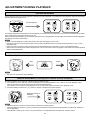
ALARM RECORDING
It is possible to switch from all recording modes to the 3H - L24H recording mode by applying an alarm signal to
the SET IN terminal on the rear panel.
ALARM SET INPUT
• It is possible to switch to the alarm recording by applying the set signal from the alarm sensor during recording in 3H,L12H, L24H, 48H - 960H or 0H mode.
3H - 960H, 0H
RECORDING
3H - 960H, 0H 3H
3H - L24H
RECORDING RECORD- RECORDING
ING
15sec
ALARM mode
NORMAL mode
•
•
•
•
NORMAL mode
Set the alarm recording mode and alarm recording period with the “RECORDING SET UP” menu. (See page 10.)
The index signal is automatically recorded when an alarm recording begins. (INDEX indicator flashes on the fluorescent display.)
To record the index signal, the first 15 seconds of the alarm recording are in 3H mode.
While the index signal is being recorded (for 15 seconds), if another set signal is applied to the SET IN terminal, it will not trigger a
new alarm recording.
ALARM RECORDING CONNECTION
External alarm lamp
or buzzer
Alarm set
switch
SET
RST
IN
REC GND ALM MODE
•
CLK CALL
OUT
RESET
IN
MIC
IN
OUT
AUDIO
IN
The alarm can be confirmed from a distance by
connecting the ALM (ALARM) OUT terminal to
an existing alarm system panel or other external
devices such as a buzzer.
VIDEO
OUT
OUT
S-VIDEO
REMOTE
Alarm reset switch
EXTERNAL TIME CLOCK ADJUSTMENT
*1
SET
RST
IN
REC GND ALM MODE
CLK
CALL
OUT
SET
RST
IN
1st VCR
REC GND ALM MODE
CLK
CALL
OUT
2nd VCR
If the “ALARM REC DURATION” of the “RECORDING SET UP” menu is set to other than “MAN1”, the on-screen clock can be reset to
the nearest hour, by applying a signal to the RST (RESET) IN terminal. For example, if the current time is 11:29:59, it will be reset to
11:00:00; and if the current time is 11:30:00, it will be reset to 12:00:00.
*1: When connecting the MODE terminal of the 1st VCR with RST (RESET) IN terminal of the 2nd VCR and if the “MODE OUT” of the
“REAR TERMINAL” menu is set to “CLOCK ADJ”, the on-screen clock of the 2nd VCR will automatically be adjusted to that of the 1st
VCR.
22
SETTING FOR ALARM RECORDING
Alarm Recording is used to activate more rapid recording when the VCR is recording in one of the Time Lapse modes. Alarm Recording
provides for more pictures during the Alarm duration. Emergency Recording enables Alarm Recording even if the VCR is off, stopped
or in Timer Recording/Standby. You should set the Alarm Recording mode with the “RECORDING SET UP” menu before Alarm
Recording is used.
1 Press the DISPLAY button to display MAIN MENU on the monitor.
2 Turn the JOG dial to select “RECORDING SET UP”
and turn the SHUTTLE ring to the right.
• “RECORDING SET UP” menu will appear.
3 Turn the JOG dial to select “ALARM REC MODE” and
turn the SHUTTLE ring to the right.
4 Turn the JOG dial to set the alarm recording mode
and turn the SHUTTLE ring to the right.
5 Turn the JOG dial to select “ALARM REC DURATION” and
turn the SHUTTLE ring to the right.
6 Turn the JOG dial to set the alarm recording duration from 15 seconds to 10 minutes, MAN1 or
MAN2 (manual). When the desired setting is shown, turn the SHUTTLE ring to the right.
• If the “ALARM REC DURATION” is set to “MAN1”, alarm recording will continue until a signal
is applied to the RST (RESET) IN terminal. If the signal applied to the RST (RESET) IN
terminal is within the first 15 seconds of alarm recording, alarm recording will continue for 15
seconds, then stop.
• If the “ALARM REC DURATION” is set to “MAN2”, alarm recording will continue until the
signal applied to the SET IN terminal is removed. If the signal applied to the SET IN terminal
is removed within 15 seconds of the start of alarm recording, alarm recording will continue for
15 seconds, then stop.
• The internal time clock can be adjusted if a signal is applied to the RST (RESET) IN terminal
on the rear panel when the ALARM REC DURATION is set to other than “MAN1”.
7 Turn the JOG dial to select “EMERGENCY RECORDING” and turn the SHUTTLE ring to the
right.
• Turn the JOG dial to select “ON”.
8 Press the DISPLAY button.
• The present time display will appear.
<MAIN MENU>
DISPLAY
TIME DATE SEARCH
TIMER PROGRAM
RECORDING SET UP
REAR TERMINAL
MAINTENANCE
FIRST TIME SET UP
Use JOG to select,
and ENTER.
Press DISPLAY to exit.
<RECORDING SET UP>
ALARM REC MODE
ALARM REC DURATION
EMERGENCY REC
3H
1M
OFF
<RECORDING SET UP>
ALARM REC MODE
ALARM REC DURATION
EMERGENCY REC
3H
1M
OFF
<RECORDING SET UP>
ALARM REC MODE
ALARM REC DURATION
EMERGENCY REC
3H
1M
ON
^ During alarm recording, the alarm recording count will automatically be displayed except when DISPLAY mode “4” is selected.
• The alarm recording count display counts up to 9999 alarm recordings and then it is reset to 0000 and continues counting.
• When initializing the alarm recording list, the alarm recording count display will be reset.
• The alarm indicator flashes during alarm recording and lights up when the alarm recording is finished.
• When the alarm recording is finished, the VCR resumes recording in the same record modes as before the alarm recording.
N
• If a set signal is applied during alarm recording, a new alarm recording will start with the new set signal. Should one SET signal
be applied within 15 seconds of another, the later SET signal will be ignored and a new alarm recording will not take place.
• Alarm recording will continue for the duration of time which has been set in the “ALARM REC DURATION” menu, even if a timer
recording has reached its end time.
• Alarm recording stops when the end of the tape is reached.
EMERGENCY RECORDING
Emergency Alarm Recording can start recording when an Alarm is triggered even if the VCR is off, stopped or in Timer Recording/
Stand-by. Turn the JOG dial to select “EMERGENCY RECORDING” and turn the SHUTTLE ring to the right.
Turn the JOG dial to select “ON” to select Emergency Recording, or “OFF” to disable it.
•
“EMGCY” lights up on the fluorescent display when the “EMERGENCY REC” of the “RECORDING SET UP” menu is set to “ON”.
23
ALARM RECORDING
ALARM RECORD TIME DISPLAY
When alarm recordings begin, the start times are stored in memory, so it is possible to confirm when they
have occurred. Select the “ALARM LIST” in the “MAINTENANCE” menu and the alarm list display will
appear on the screen.
• Up to 3 alarm recording start times can be stored in memory. For more than that, the first and the last 2
times will be displayed.
• The alarm recording list is reset by the following procedure.
1. Select the “ALARM LIST CLEAR” in the “MAINTENANCE” menu.
2. Turn the SHUTTLE ring to the right. “ALARM LIST CLEAR” will be displayed.
3. Turn the SHUTTLE ring to the left. “ALARM LIST” will be cleared.
<ALARM LIST>
0001
05 - 01 - 99 01 : 00
0002
07 - 01 - 99 21 : 10
0003
10 - 01 - 99 09 : 15
LOCATING THE START OF ALARM RECORDINGS
This machine automatically inserts an index signal at the beginning of each ALARM RECORDING, allowing the start of each alarm
to be located.
^ INDEX SEARCH
During fast forward or rewind the machine will search for index signals. When an Index signal is found, the VCR will playback the
tape and stay in still mode.
1 Press the COUNTER MEMORY/SKIP/INDEX button to illuminate “INDEX” on the fluorescent display.
(On the fluorescent display “INDEX” will be illuminated and the number indication will be illuminated.)
2 Turn the JOG dial to display the number (1-15) corresponding to the alarm index you desire to locate.
3 Turn the SHUTTLE ring to the right (forward direction) or left (reverse direction).
(The program indication number will decrease one by one as each index signal goes by.)
• The index signal may be difficult to locate in some recording conditions.
Present position
Rewind direction
Fast forward direction
ALARM
RECORDING
ALARM
RECORDING
ALARM
ALARM
RECORDING RECORDING
+1
-1
-15
ALARM
RECORDING
+2
+15
^ SKIP SEARCH
The VCR will fast forward or rewind until an index signal is located and then playback for about 4 seconds in 3H mode. This process
is repeated until the end or beginning of the tape is reached.
Present position
1 Press the COUNTER MEMORY/SKIP/INDEX button to illuminate
“SKIP” on the fluorescent display.
2 Turn the SHUTTLE ring to the right or left.
Index
Index
ALARM
RECORDING
Fast forward
Approx. 4 sec.
playback
Fast forward
ALARM
RECORDING
Fast forward
Approx. 4 sec.
playback
Until the index signal is located, the machine will fast forward (or rewind). When an index signal is located, the machine will playback
(in 3H mode) for about 4 seconds. This process will be repeated until the end or the beginning of the tape is reached.
• When the desired position is located, press the PLAY button.
• To stop SKIP SEARCH, press the STOP button.
• The index signal may be difficult to locate in some recording conditions.
24
PLAYBACK
2
5
EJECT
S-VHS
OFF
ON
JOG/ADJUST
REC
POWER
SHUTTLE
CLEAR/
ENTER/
REW
FF
STOP
PICTURE
DISPLAY
SOFT
SHARP
POSITION/
TRACKING VERTICAL
ADJUST
COUNTER
RESET
COUNTER MEMORY/
SKIP/INDEX
REC/PLAY
MODE
TIMER REC
4
PLAY
PAUAE
SHUTTLE HOLD
3
SHUTTLE ring
1 Set the VIDEO MODE In the FIRST TIME SET UP menu to either COLOUR or B/W.
• When B/W is set, colour recordings are played without colour.
2 Load a pre-recorded tape.
AUTO PLAY: If a cassette with the erasure prevention tab removed is loaded, the unit automatically begins playback mode.
3 Press the PLAY button to start playback.
4 Press the REC/PLAY MODE (+) or (-) button to select the desired playback mode.
5 Press the STOP button to stop playback.
^ Turn the SHUTTLE ring to the left to rewind the tape when the VCR is in the stop mode.
^ Turn the SHUTTLE ring to the right to fast forward the tape when the VCR is in the stop mode.
^ PLAYBACK MODE
• When the REC/PLAY MODE button is pressed, the playback mode is switched in the order of 3H } L12H } 12H } L24H } 24H
} 48H } 72H } 96H } 120H } 168H } 240H } 360H } 480H } 720H } 960H } 0H } 3H }.
Playback mode
3H
L12H
L24H
12H - 960H
Audio playback
Available
Available
Available
Not Available
Picture quality
Good
Vibrating
Vibrating
Less Vibrating
N
•
If a recording is played back in a higher mode than it was recorded, the picture will be played back in slow motion, and if a recording
is played back in a lower mode than it was recorded, the picture will be played back in fast motion.
•
The picture may move up/down or noise may occur when the tape is played back in L12H, 12H, L24H, 24H - 960H mode (even if the
tape was recorded in L12H, L24H, 48H - 960H mode).
^ AUDIO PLAYBACK
•
The modes with the letter “L” (L12H or L24H) are for audio recording and playback on the linear track.
N
•
There is normal sound playback only when a tape recorded in 3H-L24H modes is played back in its respective mode.
^ When the end of the tape is reached.
The following functions are automatically engaged when tape end is reached during playback or fast forwarding.
Tape End Selected
“REPEAT” or “ALARM • PROT”
“STOP” or “REWIND”
Playback
The tape automatically rewinds to the beginning
and stops.
Stop
Fast forward
Stop
Stop
25
SPECIAL EFFECTS PLAYBACK
The following convenient functions are available. Audio output is muted during special effects playback.
SHUTTLE RING
6
7
5
You can adjust the speed by using the SHUTTLE ring.
1 Press the PLAY button to begin playback.
2 Press the PAUSE/SHUTTLE HOLD button to obtain a
still picture.
3 Turn the SHUTTLE ring to the angle for the desired
playback speed.
N
• If the SHUTTLE ring is released, it will come back to
the centre position and still mode will be resumed.
• Pressing the PAUSE/SHUTTLE HOLD button while turning and holding the SHUTTLE ring in step 3, continues
the playback speed you selected even though the SHUTTLE ring is released.
1/30
1/30
1/15
4
3
3
2
9
2
7
1 Reverse high speed search
2 Reverse speed search
3 Reverse fast playback (x3)
4 Reverse playback
5 Reverse slow
6 Still
3
DIRECT SHUTTLE RING
2
4
5
3
6
2
5
7
1 Reverse high speed search
2 Reverse speed search
3 Reverse fast playback (x3)
4 Normal playback
B
7 Slow playback
8 Normal playback
9 Fast playback (x2)
A Forward speed search
B Forward high speed search
5
1
A
5
5
7
1
You can also change the playback speed without entering
the PAUSE mode by turning the SHUTTLE ring during playback.
If you release the ring, it will come back to the centre position, and normal playback will resume.
8
1/15
1/7
1/7
7
7
5 Fast playback (x2)
6 Forward speed search
7 Forward high speed search
STILL PICTURE
If you press the PAUSE/SHUTTLE HOLD button during playback, you will obtain a still picture.
Press the PAUSE/SHUTTLE HOLD button again to resume the normal playback mode.
N
• A few noise bars or vertical movement may appear during still playback.
FRAME BY FRAME PLAYBACK
You can use the JOG dial to advance the tape frame by frame.
1 While the VCR is playing a tape, press the PAUSE/SHUTTLE HOLD button to freeze the picture on screen.
2 Slightly rotate the JOG dial clockwise to advance the tape forward. Slightly rotate it counterclockwise to reverse the tape. To obtain
a frame by frame picture continuously, keep rotating the JOG dial.
3 To resume normal playback, press the PLAY button.
N
• When switching between forward and reverse playback, noise bars may appear on the picture.
• A few noise bars or vertical movement may appear during frame by frame playback.
26
ADJUSTMENT DURING PLAYBACK
TRACKING ADJUSTMENT
If noise appears in the picture during playback, fast playback, reverse playback or forward/reverse slow playback, adjust the TRACKING
buttons to achieve the best picture.
If noise appears
TRACKING
POSITION/
VERTICAL
ADJUST
TRACKING
POSITION/
VERTICAL
ADJUST
For tracking adjustment at fast playback, reverse playback or forward/reverse slow playback mode, press the PAUSE/SHUTTLE HOLD
button while turning and holding the SHUTTLE ring.
When pressing the TRACKING (+) and (-) buttons at the same time during playback, reverse playback or forward/reverse slow playback,
the tracking is set to the initial setting.
N
• When in reverse playback or reverse slow mode, noise bars may appear on the screen.
• Noise bars will move continuously through the picture when a TRACKING button is pressed and held (except in L12H or L24H
playback mode).
• Noise bars will move through the picture each time the TRACKING button is pressed (in L12H or L24H playback mode).
• When a picture recorded in 3H mode is played back in L12H or L24H mode, noise may appear on the screen even though adjusted
with the TRACKING button.
PICTURE QUALITY ADJUSTMENT
This control allows you to adjust the playback picture so that the outline is sharper or softer.
SOFT
SHARP
PICTURE
SOFT
SHARP
N
• This control is only effective during playback.
VERTICAL ADJUSTMENT (Correcting picture vibration at the top and bottom)
The picture vibration can be reduced or eliminated by the following steps.
1 If the vibration occurs in still, slow motion, fast playback (x2) or normal playback in 24H - 960H or 0H mode, playback a tape
which is recorded in 3H mode with this VCR and press the PAUSE button.
If the vibration occurs during normal playback in L12H or L24H mode, playback a tape in each playback mode.
2 Press the VERTICAL ADJUST (+) or (-) button to reduce or eliminate the picture vibration.
When the picture is
vibrating
TRACKING
POSITION/
VERTICAL
ADJUST
TRACKING
POSITION
VRTTICAL
ADJUST
N
• Horizontal vibration cannot be corrected with the VERTICAL ADJUST buttons.
• When the VERTICAL ADJUST (+) and (-) buttons are pressed at the same time during still playback, the VERTICAL ADJUST is
set to initial setting.
• When QUASI V-SYNC is set to “OFF”, the picture vibration is not adjustable with the VERTICAL ADJUST buttons.
27
USING WITH THE PERSONAL COMPUTER
CONFIGURING THE TIME LAPSE VCR
N
Before connecting the hardware, unplug the power cord of the VCR from the wall
outlet, and turn the personal computer power off.
1 Connecting the VCR to a personal computer.
a. Connect the RS-232C cross cable to the RS232C terminal of the personal computer.
b. Connect the other end of cable to RS-232C IN
terminal on the VCR.
Personal computer
N
• Refer to page 30 for the RS-232C cable
configuration.
To RS-232C terminal
RS-232C cross cable
To RS-232C
IN terminal
SET
RST
IN
REC GND ALM MODE
IN
RS-232C
CLK CALL
OUT
RESET
IN
ÉMIC
IN
OUT
AUDIO
IN
VIDEO
OUT
OUT
S-VIDEO
REMOTE
OUT
2 Connecting multiple VCRs to a personal computer.
Up to 16 VCRs may be controlled either individually or as a group. To do
this, connect the VCRs in series through the RS-232C IN and OUT
connectors of the interface board.
Personal computer
To RS-232C terminal
RS-232C cross cable
1st VCR
To RS-232C IN terminal
IN
RS-232C
To RS-232C OUT terminal
a. Connect the RS-232C cross cable to the RS232C terminal on the personal computer.
b. Connect the other end of the cable to the RS232C IN terminal to the 1st VCR.
c. Connect the end of the RS-232C cross cable
to the RS-232C OUT terminal of the 1st VCR
and the other end to the RS-232C IN terminal
of the 2nd VCR.
d. Continue this process until the last (up to 16)
VCR is connected.
OUT
RS-232C cross cable
2nd VCR
To RS-232C IN terminal
IN
RS-232C
To RS-232C OUT terminal
OUT
RS-232C cross cable
To RS-232C IN terminal
To RS-232C OUT terminal
RS-232C cross cable
16th VCR
To RS-232C IN terminal
IN
RS-232C
OUT
28
N
• RS-232C OUT terminal should be connected
to a time lapse VCR with RS-232C interface
board. This terminal can not be used to
connect to other general equipment with RS232C connector.
RS-232C SETTING
Set the RS-232C interface board setting by using the on screen menu of the VCR.
1 Press the DISPLAY button to display MAIN MENU.
• “MAIN MENU” will appear.
<MAIN MENU>
DISPLAY
TIME DATE SEARCH
TIMER PROGRAM
RECORDING SET UP
REAR TERMINAL
MAINTENANCE
FIRST TIME SET UP
Use JOG to select,
and ENTER.
Press DISPLAY to exit.
2 Turn the JOG dial to select “FIRST TIME SET UP”.
<MAIN MENU>
DISPLAY
TIME DATE SEARCH
TIMER PROGRAM
RECORDING SET UP
REAR TERMINAL
MAINTENANCE
FIRST TIME SET UP
Use JOG to select,
and ENTER.
Press DISPLAY to exit.
3 Turn the SHUTTLE ring to the right .
• “FIRST TIME SET UP” menu will appear.
4 Turn the JOG dial to select “RS-232C”.
• If “RS-232C interface board” is installed correctly, “RS-232C” item will appear on
“FIRST TIME SET UP” menu.
N
• If the “RS-232C” item does not appear, press the RESET button on the rear panel of
the VCR.
5 Turn the SHUTTLE ring to the right .
• “RS-232C” setting menu will appear.
Select the parameter to be changed by using the SHUTTLE ring. Change its value
using the JOG dial and then use the SHUTTLE ring to store the new value.
<FIRST TIME SET UP>
STOP
TAPE END
ON
QUASI V-SYNC
E-180
TAPE LENGTH
COLOUR
VIDEO MODE
NORMAL
PB HEAD SELECT
WRNG
BUZZER
TIME DATE ADJUST
RS-232C
<RS-232C>
TRANSMISSION RATE
DATA BIT LENGTH
STOP BIT LENGTH
PARITY BIT
DELIMITTER<SEND>
DELIMITTER<RECEIVE>
VCR ADDRESS
1200
8BIT
1BIT
NONE
CR
CR
NONE
1
SETTING TRANSMISSION RATE
When the JOG dial is turned to the right, the display will be switched in the order of 1200(bps) } 2400(bps) } 4800(bps)
}9600(bps) } 1200(bps) } ....
2
SETTING DATA BIT LENGTH
When the JOG dial is turned to the right, the display will be switched in the order of 8 BIT } 7 BIT } 8 BIT } ....
3
SETTING STOP BIT LENGTH
When the JOG dial is turned to the right, the display will be switched in the order of 1 BIT } 2 BIT } 1 BIT } ....
4
SETTING PARITY BIT
When the JOG dial is turned to the right, the display will be switched in the order of NONE } ODD } EVEN} NONE } ....
N
• The Parity bit cannot be used when the DATA BIT LENGTH is set to 8.
5
SETTING DELIMITER<SEND> (Setting a character marking the end of a command.)
When the JOG dial is turned to the right, the display will be switched in the order of CR } CR•LF } CR } ....
6
SETTING DELIMITTER<RECEIVE> (Setting a character marking the end of a status or error code.)
When the JOG dial is turned to the right, the display will be switched in the order of CR } CR•LF } CR } ....
7
SETTING VCR ADDRESS (Setting the ID number of the VCR)
When the JOG dial is turned to the right, the screen display will be switched in the order of NONE } VCR01 } VCR02} VCR03
} ... } VCR14 } VCR15 } VCR16} NONE } ....
• When controlling only one VCR via the personal computer, “VCR ADDRESS” is set to “NONE”.
• When two or more VCRs are to be controlled in series, each VCR must have a unique VCR ADDRESS (from VCR01 to
VCR16).
N
• Set the communications parameters (items 1 - 6 above) to the same values as the controlling personal computer or other
equipment. Each VCR must have the same settings when multiple VCRs are connected.
29
USING WITH THE PERSONAL COMPUTER
CONNECTING TO A PERSONAL COMPUTER
A personal computer that has an RS-232C serial port can be used to remotely control VCRs that have the RS-232C
interface board installed.
Physical protocol of RS-232C
No.
D-SUB 9pin male
5
4
9
3
8
2
7
1
6
RS-232C IN
D-SUB 9pin male
5
4
9
3
8
2
7
1
6
RS-232C OUT
2
3
4
5
6
7
8
Signal line
names
RD
SD
ER
SG
DR
RS
CS
Meanings
Receive data
Transmitt data
Data terminal ready
Signal ground
Data set ready
Request send
Clear to send
Directions
(from VCR side)
INPUT
OUTPUT
OUTPUT
–
INPUT
OUTPUT
INPUT
Data Communications Settings
Synchronization
Transmission rate
Data bit length
Stop bit length
Parity bit
X control
S parameter
CS-RS hand-shake
Delimiter code for send
Delimiter code for receive
Asynchronous
1200/ 2400/ 4800/ 9600 bps
8bits/ 7bits
1bit/ 2bits
Nil/ Even/ Odd
Nil
Nil
With
CR(0DH)/ CR(0DH)+LF(0AH)
CR(0DH)/ CR(0DH)+LF(0AH)
Connections
Before connecting the hardware, unplug the power cord of the VCR from the outlet, and turn the personal computer power
off. Connect the RS-232C IN terminal of the VCR to the personal computer's serial port.
Cable connections
1 When the RS-232C connector of the computer is DSUB 25pin.
Frame
RD 2
SD 3
ER 4
SG 5
DR 6
RS 7
CS 8
D-SUB 9 pin female
(RS-232C interface board)
2 When the RS-232C connector of the computer is DSUB 9pin.
• When connecting with 2 or more VCRs, use the
following cross cable.
1 FG
2 RD
3 SD
4 ER
5 SG
6 DR
7 RS
20 CS
FRAME
RD 2
SD 3
ER 4
SG 5
DR 6
RS 7
CS 8
D-SUB 9 pin female
D-SUB 25 pin male
(Computer)
30
FRAME
2 RD
3 SD
4 ER
5 SG
6 DR
7 RS
8 CS
D-SUB 9 pin female
The commands sent from the personal computer (or other equipment) to the VCR and responses produced by the VCR are
detailed in this section.
1 When controlling only one VCR via the personal computer, the "VCR ADDRESS" is set to "NONE".
(Refer to page 29, item 7.)
1. Command:
Format:
2. Status:
Format:
Commands sent to the VCR.
Command
Codes
Parameter
1
,
Parameter
2
,
•••••
,
Parameter
n
Delimitter
#1
,
•••••
,
Parameter
n
Delimitter
#2
Response codes from the VCR.
Status
Parameter
1
,
Parameter
2
N
#1: When you set "DELIMITTER<RECEIVE> to "CR", input the carriage return code (0DH).
When you set "DELIMITTER<RECEIVE> to "CR • LF", input the carriage return code (0DH) and line feed code (0AH).
#2: When you set "DELIMITTER<SEND> to "CR", the carriage return code (0DH) will be inputted.
When you set "DELIMITTER<SEND> to "CR • LF", the carriage return code (0DH) and line feed code (0AH) will be
inputted.
[Example 1]
Switch on the VCR. (When the DELIMITTER<SEND> and DELIMITTER<RECEIVE> of the RS-232C menu is
set to CR.)
Sending commands
from the PC etc.
Status or error code from
the VCR to PC etc.
Power ON command
Command received
Command carried out
PW1 CR
RC CR
EX CR
•
CR , which indicates carriage return code (0DH).
[Example 2]
Recording was attempted, but could not because the erasure prevention tab of the tape was broken. (When the
DELIMITTER<SEND> and DELIMITTER<RECEIVE> of the RS-232C menu is set to CR.)
Sending commands
from the PC etc.
Status or error code from
the VCR to PC etc.
Meaning
Command for recording
Command received
Failed because the erasure prevention
tab of the tape is broken.
RC CR
RC CR
ER02 CR
•
Meaning
CR , which indicates carriage return code (0DH).
31
USING WITH THE PERSONAL COMPUTER
2 When controlling two or more VCRs from a personal computer, the "VCR ADDRESS" of each VCR is set to the different
address (from VCR01 to VCR16, except NONE). ( Refer to page 29, item 7.)
•
•
Input the "VCR ADDRESS (eg.VCR01)" that you want to control and the ", (comma)" before inputting the command code.
When you want to control all connected VCRs, inputs the "ALL" and ", (comma)" before inputting the command codes.
1. Command:
Command codes from outside to the VCR.
Format:
VCR ADDRESS
,
or ALL
2. Status:
Command
Codes
Parameter
1
,
Parameter
2
,
•••
,
Parameter
n
Delimitter
#1
,
Parameter
2
,
•••
,
Parameter
n
Delimitter
#2
Response codes from the VCR to outside.
Format:
,
VCR ADDRESS
Status
Parameter
1
N
#1: When you set "DELIMITTER<RECEIVE> to "CR", input the carriage return code (0DH).
When you set "DELIMITTER<RECEIVE> to "CR • LF", input the carriage return code (0DH) and line feed code (0AH).
#2: When you set "DELIMITTER<SEND> to "CR", the carriage return code (0DH) will be inputted.
When you set "DELIMITTER<SEND> to "CR • LF", the carriage return code (0DH) and line feed code (0AH) will be
inputted.
[Example 1]
Fast forward the tape in the VCR of the ID number VCR02. (When the DELIMITTER<SEND> and
DELIMITTER<RECEIVE> of the RS-232C menu is set to CR.)
Sending commands
from the PC etc.
Status or error code from
the VCR to PC etc.
Command for fast forwarding (VCR02)
Command received (VCR02)
Command carried out (VCR02)
VCR02,FF CR
VCR02, RC CR
VCR02, EX CR
•
CR , which indicates carriage return code (0DH).
[Example 2]
Set the clock of the all VCR connected to 12:27. (When the DELIMITTER<SEND> and DELIMITTER<RECEIVE>
of the RS-232C menu is set to CR.)
Sending commands
from the PC etc.
Status or error code from the
VCR to PC etc.
VCR01,
VCR01,
VCR02,
VCR02,
Meaning
Command for recording
Command received (VCR01)
Command carried out (VCR01)
Command received (VCR02)
Command carried out (VCR02)
•
••
Command received (VCR16)
Command carried out (VCR16)
ALL,SC12,27 CR
RC CR
EX CR
RC CR
EX CR
••
•
VCR16, RC CR
VCR16, EX CR
•
•
Meaning
CR , which indicates carriage return code (0DH).
The order and number of the status responses from the VCRs to the PC or other controller may vary dependent upon the
number of VCRs and the ID number settings.
32
COMMANDS AND RESPONSES
•
•
•
NO.
1
2
3
4
5
6
7
8
9
10
11
12
13
14
15
16
17
18
19
#1 : Input the code according the DELIMITTER<RECEIVE> setting {CR (0DH) or CR (0DH) + LF (0AH)}.
#2 : The code according the DELIMITTER<SEND> setting {CR (0DH) or CR (0DH) + LF (0AH)} will be inputted.
+, which indicates one character or number. (eg. +++ indicates three characters or numbers.)
Commands
PW #1
PW0 #1
PW1 #1
EJ #1
SP #1
PB #1
RP #1
FF #1
RW #1
RC #1
CM #1
PU #1
PU0 #1
PU1 #1
FA #1
RA #1
SF #1
SR #1
IF+++ #1
20
IR+++ #1
21
IN
22
23
24
25
TR #1
TR0 #1
TR1 #1
TP #1
26
SS
#1
#1
Functions
Power ON/OFF
Power OFF
Power ON
Eject
Stop
Playback
Reverse playback
Fast forward
Rewind
Recording
Counter memory stop
Pause ON/OFF
Pause OFF
Pause ON
Forward frame advance (still only)
Reverse frame advance (still only)
Skip search (fast forward)
Skip search (rewind)
Index search (fast forward) up to
(+++=001-255)
Index search (rewind) up to (+++=001255)
Enquiry about current index No.
(index search only)
Timer recording ON/OFF
Timer recording OFF
Timer recording ON
Enquiry about current executing timer
program No.
Enquiry about current VCR status
33
Status after normal execution
RC #2 EX #2
↑
↑
↑
↑
↑
↑
↑
↑
↑
↑
↑
↑
↑
↑
↑
↑
↑
↑
Explanation of status
Command received and carried out
↑
↑
↑
↑
↑
↑
↑
↑
↑
↑
↑
↑
↑
↑
↑
↑
↑
↑
↑
↑
RC
#2
ID+++ #2
RC #2 EX #2
↑
↑
RC #2 TN+ #2
RC
RC
RC
RC
RC
RC
RC
RC
RC
RC
RC
RC
RC
RC
RC
RC
RC
RC
RC
RC
RC
RC
RC
RC
RC
RC
RC
RC
#2
ST00
ST01
#2 ST02
#2 ST03
#2 ST04
#2 ST05
#2 ST06
#2 ST07
#2 ST08
#2 ST09
#2 ST10
#2 ST11
#2 ST12
#2 ST13
#2 ST14
#2 ST15
#2 ST16
#2 ST17
#2 ST18
#2 ST19
#2 ST20
#2 ST21
#2 ST22
#2 ST23
#2 ST24
#2 ST25
#2 ST26
#2 ST27
#2
#2
#2
RC
RC
RC
RC
RC
#2
ST29
ST30
#2 ST32
#2 ST33
#2 ST34
#2
#2
#2
#2
#2
#2
#2
#2
#2
#2
#2
#2
#2
#2
#2
#2
#2
#2
#2
#2
#2
#2
#2
#2
#2
#2
#2
#2
#2
#2
#2
#2
Index No. is +++=001-255
Command received and carried out
↑
↑
Timer program No. is +=1-8
(Note)ER08, when not timer recording
Power off, cassette in
Power off, cassette out
Power on, cassette in
Power on, cassette out
Fast forward underway
Rewind underway
Recording underway
Recording pause underway
Playback underway
Reverse playback underway
Forward speed search underway
Reverse speed search underway
Still underway
Counter memory search underway
Skip search (fast forward) underway
Skip search (rewind) underway
Playback during skip search
Index search (fast forward) underway
Index search (rewind) underway
Rewind during repeat recording
Alarm recording underway
Timer recording underway
Reserve of timer recording
Timer reserve error underway
Time date search stand-by underway
Time date FF search underway
Time date REW search underway
Time date search or index search point
adjustment underway
Recording check underway
Index writing underway
One shot recording underway
Forward-advance underway
Reverse advance underway
USING WITH THE PERSONAL COMPUTER
NO.
27
Commands
LO+ #1
28
LM #1
29
30
31
CR #1
CT #1
MC+++ #1
32
MD
33
34
DP #1
DP+++
35
PI
36
SD++(1),++(2),++(3) #1
37
DT #1
38
SC++(1),++(2) #1
39
40
41
TM #1
TD #1
PS++(1),++(2) #1
42
43
LC #1
PG+(1),+(2),++(3),++(4),
++(5),++(6),+++(7),+(8) #1
#1
#1
#1
Functions
Lock ON/OFF
+:0=OFF, 1=ON
Enquiry about current lock status & lock
mode
Counter reset
Enquiry about current count display value
Switch over time mode to
+++ = 003, L12, L24, 048, 072, 096, 120,
168, 240, 360, 480, 720, 960, 000
Enquiry about current time mode
Status after normal execution
RC #2 EX #2
Explanation of status
Command received and carried out
RC
#2
+:
RC
RC
RC
#2
RC
#2
MD+++(1),+(2) #2
Main menu ON/OFF
Switch screen page to
(+++ :
000=present time display
100=MAIN MENU display
110=Display menu
120=TIME DATE SEARCH display
130=PROGRAM menu
140=RECORDING SET UP menu
150=REAR TERMINAL menu
160=MAINTENANCE menu
161=POWER LOSS LIST
162=ALARM LIST
163=ALL MENU INITIALIZE
164=POWER LOSS LIST CLEAR
165=ALARM LIST CLEAR
170=FIRST TIME SET UP menu
171=TIME DATE ADJUST
172=RS-232C setting menu)
Enquiry about current screen page
RC
↑
#2
EX #2
RC
#2
ON+++(1)+(2) #2
Current date setting
++(1) : Day, ++(2) : Month, ++(3) : Year
Enquiry about current date
RC
#2
EX #2
Current time setting
++(1):Hour, ++(2):Minute
Enquiry about current time
Enquiry about power loss mark
Move date display position
++(1) : Horizontal
= 03-16 (mode 1, size large)
= 05-28 (mode 1, size small)
= 03-21 (mode 2,3, size large)
= 00-28 ( mode 2,3, size small)
++(2) Vertical
= 02-30 (mode 1, size large or small)
= 02-30 (mode 2,3, size large or small)
Enquiry about date display position
Timer program setting
+(1)Program No.=1-8
+(2):Day of the week(0=SUN,1=MON,2=TUE,
3=WED,4=THU,5=FRI,6=SAT,7=DAY,8=SPL)
++(3):Rec starting hour=00-23
++(4):Rec starting minute=00-59
++(5):REC ending hour=00-23
++(6):REC ending minute=00-59
+++(7):REC time mode=003, L12, L24,
048, 072, 096, 120, 168, 240, 360, 480,
720, 960, 000, SKP
+(8):REC mode 0=SP
RC
LM+
#2
EX #2
CT+++++ #2
#2 EX #2
#2
RC #2 TD++(1),++(2),++(3),+(4) #2
34
#2
EX #2
0=Lock off
2=Lock on
Command received and carried out
+++++=00000-99999
Command received and carried out
+++(1)= 003, L12, L24, 048, 072, 096, 120,
168, 240, 360, 480, 720, 960, 000
+(2)= SP
Command received and carried out
↑
+++(1) : same as item 34
: Setting completed=0,
+(2)
During setting=1
Command received and carried out
++(1)-++(3) (same as item 36)
+(4) :Day of the week
0=SUN, 1=MON, 2=TUE, 3=WED,
4=THU, 5=FRI, 6=SAT
Command received and carried out
RC #2 TI++(1),++(2),.++(3) #2
RC #2 MK+ #2
RC #2 EX #2
++(1) :Hour, ++(2) :Minute, ++(3):Second
+: 0=Not displayed, 1=On display
Command received and carried out
LT++(1),++(2) #2
EX #2
++(1),++(2) (=same as item 41)
Command received and carried out
(Note) An error (ER08) will occur if an
attempt is made to program a timer
program number that has already been
set. Clear the timer program contents
with the “CA+” command and then retry.
RC
RC
#2
#2
NO.
44
Commands
PM+ #1
Functions
Enquiry about setting contents of timer
program No. (+=1-8)
Clear contents of timer program No.
(+=1-8)
Setting the special day of the week
+(1):Setting on (0-6)
+(2)Setting off (0-6)
0=SUN, 1=MON, 2=TUE, 3=WED,
4=THU, 5=FRI, 6=SAT
Enquiry about the setting of the special
day of the week
Status after normal execution
RC #2 MP+(1),+(2),++(3),++(4),++(5),++(6),
+++(7) +(8) #2
RC #2 EX #2
RC
#2
DW+(1), +(2) #2
Alarm mode setting
++=03, 12, 24
RC
#2
EX
45
CA+
46
DW+(1),+(2) #1
47
DW?
48
AM++
49
AS1
#1
Enquire of alarm mode setting
RC
#2
AM++
50
AD+
#1
RC
#2
EX
51
52
53
54
55
56
AS0 #1
EM #1
EM0 #1
EM1 #1
AS2 #1
TE+ #1
RC
RC
↑
↑
RC
RC
#2
AP+ #2
EX #2
57
58
59
60
61
62
63
FS0 #1
DM+ #1
DM? #1
CH0 #1
CH1 #1
FS1 #1
CO+(1),++(2)
RC
RC
RC
RC
↑
RC
RC
#2
64
65
RO #1
MO+ #1
RC
RC
#2
66
67
RM #1
CU+ #1
RC
RC
#2
68
69
70
71
72
CU? #1
BL+ #1
BL? #1
ST+ #1
BZ+ #1
RC
RC
RC
RC
RC
#2
73
74
75
76
BR+ #1
FS2 #1
BP #1
OS++ #1
77
78
OF #1
OI+ #1
79
80
OI? #1
AN #1
Alarm REC duration setting
+: MAN1=0, MAN2=1, 15s=2, 30s=3,
45s=4, 1m=5, 2m=6, 5m=7, 10m=8
Enquiry about alarm REC duration setting
Emergency REC ON/OFF
Emergency REC OFF
Emergency REC ON
Enquiry about emergency REC setting
Tape end movement setting
+: STOP=0, REWIND=1, REPEAT=2,
ALARM•PROT(protect)=3
Enquiry about tape end movement set
Display mode setting (+=(1-4))
Enquiry about display mode setting
Set date character display size “SMALL”
Set date character display size “LARGE”
Enquiry about date character display size
Clock out setting
+(1):REC=0, T/LREC=1
++(2): 01, 02, 03, 04, 05, 10, 15, 20, 25,
30, 50, 60, 00(output by field)
Enquiry about clock out setting
Mode out setting
+: REC=0, PLAY=1, POWER=2 ,
TAPE IN=3, TAPE REMAIN=4,
CLOCK ADJ=5
Enquiry about MODE OUT setting
CALL OUT setting +:0=OFF, 1=ON
Receive the command only when the
signal at the MODE OUT terminal is
switched to the active condition.
Enquiry about CALL OUT setting
Blue Back setting +:0=OFF, 1=ON
Enquiry about Blue Back setting
Select menu item +:0=OFF, 1=ON
Buzzer setting
+:0=WRNG, 1=WRNG•TAPE END,
2=WRNG•REMAIN, 3=OFF
Buzzer ON/OFF setting +:0=OFF, 1=ON
Enquiry about buzzer setting
Enquiry about buzzer status
One shot field setting
++: 01, 02, 03, 04, 05, 10, 20, 30
Enquiry about one shot field setting
One shot interval setting
+: 0=SHOT, 1=10S, 2=15S, 3=30S,
4=45S, 5=1M, 6=2M, 7=3M
Enquiry about one shot interval setting
Enquiry about current alarm REC. No.
#1
#1
#1
#1
35
Explanation of status
+(1)-+(8) (=Same as item 43)
Command received and carried out
↑
↑
(Cannot accept this command when +(1)
and +(2) are the same number)
↑
RC
RC
RC
RC
RC
RC
RC
#2
#2
#2
#2
#2
#2
#2
#2
#2
#2
#2
#2
#2
#2
#2
#2
#2
#2
#2
#2
#2
#2
+(1):Start day (of the week) (0-6)
+(2):End day (of the week) (0-6)
0=SUN, 1=MON, 2=TUE, 3=WED,
4=THU, 5=FRI, 6=SAT
Command received and carried out
++=03, 12, 24
#2
Command received and carried out
#2
+(=Same as item 50)
Command received and carried out
↑
↑
+:0=OFF, 1=ON
Command received and carried out
EG+ #2
EX #2
+(=Same as item56)
Command received and carried
+ =(1-4)
Command received and carried
Command received and carried
+ : 0=SMALL, 1=LARGE
Command received and carried
TE+ #2
EX #2
DM+ #2
EX #2
CZ+ #2
EX #2
CD+(1),++(2)
EX #2
#2
out
out
out
out
+(1), ++(2)(=Same as item 63)
Command received and carried out
MR+ #2
EX #2
+(=same as item 65)
Command received and carried out
CU+ #2
EX #2
BL+ #2
EX #2
EX #2
+ : 0=OFF, 1=ON
Command received and carried out
+ : 0=OFF, 1=ON
Command received and carried out
Command received and carried out
BZ+ #2
SW+ #2
EX #2
↑
+(=same as item 72)
+:0=OFF (not ring), 1=ON (ring)
Command received and carried out
SD++
EX #2
+(=same as item 76)
Command received and carried out
#2
OI+ #2
AN++++
#2
+(=same as item 78)
++++(=0000-9999)
USING WITH THE PERSONAL COMPUTER
NO.
81
Commands
AT+ #1
82
83
84
CA #1
PN #1
PT+ #1
85
86
87
88
PC #1
MI #1
HM? #1
WN #1
89
90
CA0 #1
RI+ #1
91
92
93
94
RI? #1
QV+ #1
QM #1
CL+ #1
95
96
RL #1
SM+ #1
97
98
SM? #1
RS? #1
99
TL+
100
101
102
TL? #1
LP? #1
TF++(1), ++(2), ++(3)
#1
103
TB++(1), ++(2), ++(3)
#1
104
105
TS? #1
HD+ #1
106
107
HD? #1
MQ+ #1
108
109
SB1
SV?
#1
#1
#1
Functions
Enquiry about alarm REC list report
+: 0=about the alarm REC No. 1
1=about the second alarm REC from
the last one
2=about the last alarm REC
Clear all alarm REC list contents
Enquiry about current power loss list No.
Enquiry about power loss list report
+: 0=about the first power loss
1=about the second power loss from
the last one
2=about the last power loss
Clear all power loss list contents
Initialization of the setting
Enquiry about the elapsed time
Enquiry about Warning information
Status after normal execution
RC #2 AT++(1), ++(2), ++(3), ++(4), ++(5)
RC
↑
RC
RC
#2
EX
#2
#2
HM+++++
WN++ #2
Clear ER05
REC IN setting
+:0=SERIES, 1=REC-START/STOP
2=SYNC REC
Enquiry about REC IN setting
QUASI-VSYNC setting +:0=OFF, 1=ON
Enquiry about QUASI-VSYNC setting
CALL OUT setting
+:0=WRNG, 1=WRNG •TAPE END
2=WRNG •TAPE REMAIN
Enquiry about CALL OUT setting
DAY LIGHT SAVINGS setting
+:0=OFF, 1=ON
Enquiry about DAY LIGHT SAVINGS setting
Enquiry about REPEAT REC TIMES
RC
↑
#2
EX
RC
RC
RC
RC
#2
RI+ #2
EX #2
QV+ #2
EX #2
+ : (=Same as item 90)
Command received and carried out
+:0=OFF, 1=ON
Command received and carried out
RC
RC
#2
CL+ #2
EX #2
+ : (=Same as item 94)
Command received and carried out
RC
RC
#2
#2
SM+ #2
RS+++
Tape length setting
+:0=E-180, 1=E-240
Enquiry about tape length setting
Enquiry about tape remaining time
Time date FF search setting
++(1) : Day , ++(2) : Hour , ++(3) : Minute
Time date REW search setting
++(1) : Day , ++(2) : Hour , ++(3) : Minute
Enquiry about time date search setting
PB head switch-over
+:0=NORMAL,1=L/L, 2=R/R, 3=AUTO
Enquiry about PB head switch-over
VIDEO MODE setting
+:0=COLOUR,1=B/W
Enquiry about VIDEO MODE
Enquiry about S-VHS information
RC
#2
EX
RC #2 EX #2
RC #2 PN++ #2
RC #2 PT++(1), ++(2), ++(3), ++(4), ++(5)
#2
#2
#2
#2
#2
#2
Explanation of status
++(1) : Day, ++(2) : Month, ++(3) :Year,
++(4) : Hour, ++(5) : Minute
Command received and carried out
++(=00-99)
++(1) : Day, ++(2) : Month, ++(3) :Year,
++(4) : Hour, ++(5) : Minute
Command received and carried out
↑
+++++(=Hour)
++: Warning No. 0=not abnormal
01=tape end
03=video input missing
04=clogged head
05=reel rotation trouble
06=loading motor trouble
07=capstan motor trouble
08=drum motor trouble
09=tape loose, 10=switching power short
Command received and carried out
↑
#2
#2
#2
+:0=OFF, 1=ON
+++:000-200,
OVER ( more than 201 times )
Command received and carried out
#2
#2
RC #2 TL+ #2
RC #2 LP+(1), ++(2) #2
RC #2 EX #2
+ : (=Same as item 99)
+(1) : Hour , ++(2) : Minute
Command received and carried out
↑
↑
RC #2 TS++(1), ++(2), ++(3)
RC #2 EX #2
RC
RC
#2
RC
RC
#2
#2
#2
#2
++(1) : Day , ++(2) : Hour , ++(3) : Minute
Command received and carried out
HD+ #2
EX #2
+ : (=Same as item 105)
SQ+ #2
SV+ #2
+:0=COLOUR,1=B/W
+:0=NORMAL,1=S-VHS
Error codes
No.
1
2
3
4
5
6
7
Errors
ER00
ER01
ER02
ER03
ER04
ER05
ER06
Meaning of error
No power supply
No cassette loaded
Broken tape tab (Cannot REC)
Beginning of the tape
Tape end
Problem with the tape, video input or VCR mechanism
Present time or timer program not yet set
No.
8
9
10
11
12
13
36
Errors
ER07
ER08
ER10
ER11
ER12
ER13
Meaning of error
Alarm REC underway (Unable to change setting)
Unfeasible
Incorrect command
Incorrect parameter
Overflow of the VCR’s command receive buffer
Data not received correctly
WARNING DISPLAY
SELF DIAGNOSTIC FUNCTION
The VCR uses a self diagnostic function to detect internal malfunctions during recording. Should a malfunction occur during recording, a corresponding indication appears on the monitor screen and the fluorescent display.
The type of malfunction corresponding to the indication, and countermeasures, are given below.
Fluorescent
display
Monitor
End
TAPE END
THE TAPE ENDS DURING RECORDING
Turn off the indication on the fluorescent
Rewind the tape and
display and on the screen by pressing the
press the EJECT button.
EJECT button or rewinding the tape.
—
NO SIGNAL
LACK OF VIDEO SIGNAL INPUT (NOTE 1)
Check for loose connections.
CLOGGED HEAD
(NOTE 2)
Eject the cassette and
insert it again. If the
indication “CLog” is still
When the recording mode is cleared, the
displayed, clean the
indication on the fluorescent display turns
video cassette tape. If
the VCR still shows the off.
indication after cleaning, contact your dealer.
TAPE/ DECK TROUBLE
First, check the cassette. If there seems to be nothing wrong with
the cassette, try the recording operation again. If the indication
“CHECK” is still displayed, change the cassette with a new one
and try the operation again. Otherwise, unplug the power cord and
contact your dealer.
CLog
—
—
CHECK
CAUSE
REMEDY
TO TURN OFF THE INDICATION
When a video signal is restored or the
record mode is cleared, the indication on
the screen turns off.
N
1. Lack of video input signal.
If the VCR is set to record and an input signal is not detected, the indication NO SIGNAL appears on the monitor screen and the
CALL signal is output from the rear terminal.
Check that the cable from the camera is not broken and the camera's power has not been lost.
2. About fouling of the head (CLOGGED HEAD).
This VCR’s head cleaning function automatically removes any particles that may accumulate on the heads during 48H - 960H
(SP) or 0H recording mode. If it cannot be entirely removed, a CLog indicator illuminates.
37
BEFORE CALLING FOR SERVICE
SYMPTOM
REMEDY
VCR does not operate.
•
•
•
Is the LOCK indicator illuminated?
Has the power cord been disconnected from the AC outlet?
Is the TIMER REC indicator illuminated?
The VCR POWER is ON but unit
does not operate.
•
•
Is the LOCK indicator illuminated?
Safety devices are operating.
Press the RESET button on the rear panel using a suitable implement.
No picture is obtained on the MONITOR screen.
•
Is the video cable connected properly or is the cable defective?
No operation when any tape operation button is pressed.
•
•
Is the LOCK indicator illuminated?
Is a cassette inserted?
Recording does not work.
•
•
•
Is the LOCK indicator illuminated?
Has the cassette’s erasure prevention tab been broken off?
Has the tape run out?
Recording cannot be stopped by
pressing the STOP button.
•
•
Is the LOCK indicator illuminated?
Is the TIMER REC indicator illuminated?
Timer recording does not operate.
•
Has the present time and recording time been set accurately?
No operation when the PLAY button
is pressed.
•
•
•
Is the LOCK indicator illuminated?
Has the tape run out?
Is a cassette inserted?
Noise bars in the picture during
playback.
•
Has the TRACKING control been adjusted?
The picture vibrates at the top and
bottom when in still picture mode.
•
Has the VERTICAL ADJUST control been adjusted?
•
This symptom may occur when the recorder has been used for a long
period of time. During this time, a deposit of oxide has built up on the
video heads which must now be cleaned. Cleaning of the heads requires
expertise. Please contact your dealer.
•
Is the camera focused?
•
Make sure the VCR has mains power supplied continuously for at least 40
hours per week.
•
•
Make sure the VCR has mains power supplied continuously for at least 40
hours per week.
The contents stored in the memory may be erased before the 31 days
depending on the charge time of the power failure compensation circuit.
Set the present time again.
Repeat recording does not work.
•
•
Is the repeat recording indicator illuminated?
Is the alarm recording started?
Alarm recording does not work.
•
Is the external switch connected correctly?
Playback speed is fast or slow.
•
Is the playback mode set to the desired mode with REC/PLAY MODE
button?
Clear camera pictures during recording but during playback the picture is
not clear.
The picture is not clear on the
monitor.
The present time is not correct even
though the VCR is used everyday.
The power cord has been disconnected for less than 31days but the
present time has been reset.
38
CONTROL INPUT/OUTPUT SIGNALS AND CIRCUITS
2 SET/ RST/ REC IN terminals (screw)
Active:
When input terminals are short-circuited to GND or “L” level voltage (0 - +1.6V) applied.
Time for active: 0.1 sec or over.
Non active:
Open the input.
DC5V
SET/RST/REC IN 22kΩ
10kΩ
0.047µF
GND
<Interface circuit inside the VCR>
2 ALM/ MODE/CALL OUT terminals (screw)
Active:
“L” level voltage (0 - +0.4V) output; max. drive current 50mA(+5V DC)/
10mA(+24V DC)
Open; max. voltage +24V DC
Non active:
ALM / MODE/ CALL OUT
GND
<Interface circuit inside the VCR>
2 CLK OUT terminal (screw)
DC12V
10kΩ
CLK OUT
10kΩ
GND
<Interface circuit inside the VCR>
CLK OUT signal
• When “F” is selected in REC of CLOCK OUT mode in 3H recording.
+12V
0V
10msec
• During recording in L12H - 960H recording mode.
+12V
0V
8msec
• When except “F” is selected in REC of CLOCK OUT mode in 3H recording.
+12V
0V
20msec
39
CONTROL INPUT/OUTPUT SIGNALS AND CIRCUITS
2 REMOTE jack
Circuit
MJ
Shielded
cable
R
R
R
SW
SW
1
1)Resistor R:
SW
2 ···································· 31
2)Button switch:
3)Connector MJ:
Metal film resistor 1/4W 33kohms ±1%,
temperature factor ±100ppm/°C.
Momentary, ON resistor 200ohms or under.
Miniature jack, 2.5mm in diameter, comply with JISC6560.
Operational conditions
1)Isolation resistor:
2)Floating capacity:
3)Environmental temperature:
4)Relative temperature:
200Mohms or over (in connector MJ)
0.1µF or under (in connector MJ).
5-40°C (common with VCR).
Max. 80% (common with VCR).
SW
32
Remote control switch functions
Position
1
2
3
4
5
6
7
8
Function
STOP
RECORDING
PAUSE
PLAYBACK
REVERSE PLAYBACK
FORWARD FRAME SHIFT
FAST FORWARD
REWIND
Function
Position
9
10
11
12
13
14
15
16
Position
17
18
19
20
21
22
23
24
3H
L24H
48H
72H
120H
240H
0H
–
Function
POWER ON/OFF
REVERSE FRAME SHIFT
TIME DATE SEARCH
INDEX SEARCH
( )DISPLAY/SET
(+)DISPLAY/SET
LEFT POSITION/SHIFT
RIGHT POSITION/SHIFT
2 Remote Control (optional)
The optional Remote Control (R-7100) provides remote operation of the VCR.
Before using the remote control, put the label on it as shown in Fig.
No function is available.
REC/PLAY MODE
Label (B-7)
3H L24H
PLAY
STOP
REC
PAUSE
/STILL
REV
PLAY
FR ADV
/REW FF/
40
Position
25
26
27
28
29
30
31
32
Function
DOWN POSITION/SHIFT
UP POSITION/SHIFT
CLEAR
START/END
( )REC/PLAY MODE
(+)REC/PLAY MODE
SKIP SEARCH
TIMER RECORDING
SPECIFICATIONS
Tape Format:
Power Source:
Power Consumption:
Television System:
Heads-Video:
Luminance Signal:
Colour Signal:
Audio Track:
Tape Speed and Recording
Time (with E-180 cassette):
VHS 1/2" width high-density video cassette tape.
AC100-230V, 50/60Hz.
Approx.20watts.
625 lines, 50 field PAL-type colour system.
4 rotary single crystal heads.
Frequency modulation recording.
Low frequency conversion, sub-carrier phase shift recording.
1 track.
Fast Forward/Rewind Time:
Audio/Control:
Erase:
Motors:
Video Input:
Audio Input:
Microphone Input:
Video Output:
Audio Output:
Horizontal Resolution:
Approx. 140sec. with E-180 cassette.
1 stationary head.
1 full-track head.
3 motors-drum/capstan direct drive system.
1.0Vp-p, 75ohms BNC plug. Y: 1.0 Vp-p, 75 ohms, C: 0.286 Vp-p, 75 ohms, S-connector.
-8dBs, 50kohms, RCA plug.
-67dBs, 600ohms, mini mic jack.
1.0Vp-p, 75ohms BNC plug. Y: 1.0 Vp-p, 75 ohms, C: 0.286 Vp-p, 75 ohms, S-connector.
-6dBs, 1kohms, RCA plug.
More than 400 lines (S-VHS mode).
More than 240 lines (VHS mode).
70Hz- 7kHz (3H mode).
Video: better than 42dB.
Audio: better than 43dB.
41°F-104°F (5°C to 40°C).
Max.80(%)
16.7(W)x12.4(D)x3.7(H)(in.).
425(W)x315(D)x93(H)(mm).
10 lbs (4.5kg.)
Timed: 15 sec/30 sec/45 sec/1 min./2 min./5 min./10 min.
Manual 1: Until the alarm reset switch is switched on. Manual 2: Until the alarm set switch is switched off.
DISPLAY MODE 1: (Day)-(Month)-(Year) (Hour) : (Minute) : (Second) (Daylight saving time symbol or power failure symbol) (Alarm recording no.)
DISPLAY MODE 2: (Month)-(Day)-(Year) (Day of week) (Alarm recording no.),
(Hour) : (Minute) : (Second) (Daylight saving time symbol or power failure symbol) (Recording mode)
In any position.
8 programs- daily start and stop time for one week.
Lasts 31days.
The maximum of 89,999 hours.
Audio Frequency Response:
Signal-to-Noise Ratio:
Operating Temperature:
Relative Humidity:
Dimensions:
(Jog dial included)
Weight:
Alarm Recording Time:
Display Format:
Display Position:
Memory Program:
Memory Backup:
Elapsed Time Indicator:
CONNECTORS
SET Input:
RST Input:
REC Input:
GND:
ALM Output:
CLK Output:
MODE Output:
CALL Output:
REMOTE Jack:
RS-232C interface:
Rating:
ALM/CALL/MODE
SET/RST/REC
CLK
Mode
3H
L12H
L24H
48H
72H
96H
120H
168H
240H
360H
480H
720H
960H
0H
Time
3hrs
15hrs
27hrs
51hrs
75hrs
99hrs
123hrs
171hrs
243hrs
363hrs
483hrs
723hrs
963hrs
–
Speed
23.39mm/sec
4.68mm/sec
2.60mm/sec
–
–
–
–
–
–
–
–
–
–
–
Recording interval
20msec./Field
100msec./Field
180msec./Field
340msec./Field
500msec./Field
660msec./Field
820msec./Field
1140msec./Field
1620msec./Field
2420msec./Field
3220msec./Field
4820msec./Field
6420msec./Field
–
Video signal
Continuous
Time lapse
Time lapse
Time lapse
Time lapse
Time lapse
Time lapse
Time lapse
Time lapse
Time lapse
Time lapse
Time lapse
Time lapse
Time lapse
Audio signal
Recordable
Recordable
Recordable
Not recorded
Not recorded
Not recorded
Not recorded
Not recorded
Not recorded
Not recorded
Not recorded
Not recorded
Not recorded
Not recorded
Tape drive
Continuous
Continuous (Slow)
Continuous (Slow)
Time lapse
Time lapse
Time lapse
Time lapse
Time lapse
Time lapse
Time lapse
Time lapse
Time lapse
Time lapse
Time lapse
Screw terminal for starting alarm recording.
Screw terminal for finishing alarm recording or for adjusting on-screen clock.
Screw terminal for starting/finishing recording, for series recording or for synchronous recording.
Screw terminal for ground.
Screw terminal for output while alarm recording is under way.
Screw terminal to command camera switching.
Screw terminal for indication of VCR selected mode.
Screw terminal for external warning device or for series recording.
Jack for connecting the remote control unit.
D-SUB 9 pin connector.
Active: “Low” level, max. Current 50mA (+5VDC)/10mA (+24VDC).
Non active: Open, max. Voltage +24V DC.
Active: When terminals are short-circuited or “Low” level voltage applied.
Non active: Open, max. Voltage +17V DC.
Recording: A pulse of the frequency division ratio selected by REAR TERMINAL menu.
Weight and dimensions shown are approximate.
Design and specifications are subject to change without notice.
41
872C193C3
PRINTED IN JAPAN