1
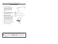
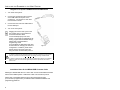
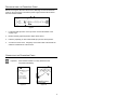
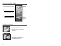
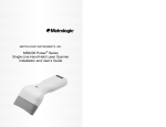
LOCATIONS
CORPORATE HEADQUARTERS
North America
Metrologic Instruments, Inc.
90 Coles Road
Blackwood, NJ 08012-4683
Customer Service: 1-800-ID-METRO
Tel: 856-228-8100
Fax: 856-228-6673
Email: [email protected]
Internet: www.metrologic.com
EUROPEAN HEADQUARTERS
Germany,
Middle East and Africa
Metrologic Instruments GmbH
Dornierstrasse 2
82178 Puchheim b.
Munich, Germany
Tel: +49 89 89019 0
Fax: +49 89 89019 200
Email: [email protected]
Germany Email: [email protected]
Spain
Metrologic Eria lbérica SL
Julián Camarillo 29, D-1
Edificio Diapasón
28037 Madrid
Tel: +34 913 272 400
Fax: +34 913 273 829
Email: [email protected]
Italy
Metrologic Instruments Italia srl
Via Emilia 70
40064 Ozzano dell’Emilia (BO)
Tel: +39 0 51 6511978
Fax: +39 0 51 6521337
Email: [email protected]
France
Metrologic Eria France SA
69 Rue de la Belle Etoile
ZI Paris Nord II, BP 50057
95947 – ROISSY CDG CEDEX
Tel: +33 (0) 1 48.63.78.78
Fax: +33 (0) 1 48.63.24.94
Email: [email protected]
United Kingdom
Metrologic Instruments UK Limited
58 Tempus Business Centre
Kingsclere Road, Basingstoke
Hampshire RG21 6XG
Tel: +44 (0) 1256 365900
Fax: +44 (0) 1256 365955
Email: [email protected]
Singapore
Metrologic Asia (Pte) Ltd
No. 8 Kaki Bukit Place
4th Floor
Singapore 416186
Tel: 65-6842-7155
Fax: 65-6842-7166
Email: [email protected]
China
Metro (Suzhou) Technologies Co., Ltd.
221 Xing Hai Street
Suzhou Industrial Park
Suzhou, China
215021
Tel: 86-512-62572511
Fax: 86-512-62571517
Email: [email protected]
Japan
Metrologic Japan Co., Ltd.
Matsunoya Building, 6 Floor
3-14-8 Higashiueno
Taitou-Ku, Tokyo 110-0015 Japan
Tel: 81-03-3839-8511
Fax: 81-03-3839-8519
Email: [email protected]
Brazil
Metrologic do Brasil Ltda.
Rua da Paz 2059
CEP 04713-002
Chácara Santo Antônio
São Paulo, SP, Brasil
Tel: 55-11-5182-8226
Fax: 55-11-5182-8315
Email: [email protected]
Outside Brazil
Metrologic South America
Rua da Paz 2059
CEP 04713-002
Chácara Santo Antônio
São Paulo, SP, Brasil
Tel: 55-11-5182-7273
Fax: 55-11-5182-7198
Email: [email protected]
ASIA
SOUTH AMERICA
Copyright
© 2003 by Metrologic Instruments, Inc. All rights reserved. No part of this work may be reproduced, transmitted, or stored
in any form or by any means without prior written consent, except by reviewer, who may quote brief passages in a review,
or provided for in the Copyright Act of 1976.
Products and brand names mentioned in this document are trademarks of their respective companies.
ii
TABLE OF CONTENTS
Introduction........................................................................................................... 1
Scanner and Accessories..................................................................................... 2
Operation Test...................................................................................................... 4
Installing the Scanner to the Host System
MS9524-00/9/11/14/41 and MS9544-00/9/11/14/41......................................... 5
Keyboard Wedge MS9524-47 and MS9544-47................................................ 6
Stand Alone Keyboard...................................................................................... 7
Integrated Full Speed USB MS9524-40 and MS9544-40 ................................. 8
Installation Notes for the MX009 USB Converter Cable ................................... 8
Disconnection the PowerLink Cable..................................................................... 9
Connecting the PowerLink Cable ......................................................................... 9
®
How to Use CodeGate - MS9544 ..................................................................... 10
Two Modes of Operation .................................................................................... 10
How to Scan PDF Bar Codes ............................................................................. 11
Stand Kits ........................................................................................................... 12
Assembling the Stands....................................................................................... 13
Scanner Parts..................................................................................................... 16
Audible Indicators............................................................................................... 17
Visual Indicators ................................................................................................. 18
Failure Modes..................................................................................................... 20
Programming Modes .......................................................................................... 21
Upgrading the Flash ROM Firmware .................................................................. 24
Labels................................................................................................................. 25
Maintenance....................................................................................................... 25
Depth of Field
Minimum Bar Code Element Width ................................................................ 26
PDF417 Minimum Bar Code Element Width .................................................. 27
IR Activation ....................................................................................................... 28
Applications and Protocols ................................................................................. 29
Troubleshooting Guide ....................................................................................... 30
RS-232 Demonstration Program ........................................................................ 34
Design Specifications ......................................................................................... 35
Default Settings .................................................................................................. 37
Scanner and Cable Terminations
Scanner Pinout Connections .......................................................................... 42
Cable Connector Configurations .................................................................... 44
Limited Warranty ................................................................................................ 46
Notices and Cautions ......................................................................................... 47
Patents ............................................................................................................... 48
Index................................................................................................................... 49
iii
INTRODUCTION
The VoyagerPDF™ series of scanners has taken the already proven and reliable
Voyager series to new levels of ability. With its introduction, Metrologic’s
VoyagerPDF™ series has added the ability to decode PDF, a 2D symbology that
includes both normal and truncated version of this bar code type. This
symbology differs from normal 1D barcodes and can be viewed as a series of 1D
segments arranged vertically. Therefore PDF codes are scanned by sweeping
the high-speed laser scan line up or down over the code gathering information
from each line. This series integrates a high performance processor with
software designed to optimize PDF417 performance. Two base models are
available, the MS9544 and MS9524.
The MS9544 includes Metrologic’s patented auto trigger and CodeGate® button
feature. Simply present a bar code to the scanner; the high-visibility
650-nanometer laser is automatically activated allowing the user to easily select
the bar code to be scanned. Press the CodeGate button and the data is
transmitted to the host system. Since scanning PDF codes requires multiple
scans, a separate programmable CodeGate feature has been added. With PDF
CodeGate disabled, PDF codes can be decoded and transmitted automatically,
without compromising the versatility achieved with CodeGate.
Equipped with both ‘in-stand’ and ‘out-of-stand’ operation, this series can be
used as both a hand-held and a fixed projection scanner. VoyagerPDF
automatically senses when it is placed in the stand and de-activates the
CodeGate button.
If the advantage of CodeGate technology is unnecessary in your application,
then the MS9524 is the VoyagerPDF of choice. The MS9524 is packed with all of
the same features as the MS9544, with the exception of CodeGate.
The VoyagerPDF series is packed with additional features such as: user
programmable Flash ROM, high speed scanning, PowerLink user-replaceable
cables, easy programming using Windows® software or bar codes, OPOS and
JPOS system compatibility, and support for commonly used interfaces including
USB.
VoyagerPDF
MS9524 – 00
VoyagerPDF
with CodeGate
MS9544 – 00
Interface
Laser Emulation*, RS-232 Transmit/Receive*
MS9524 – 9
MS9544 – 9
OCIA*
MS9524 – 11
MS9544 – 11
IBM 468X/469X*, RS232-TXD, RXD, RTS, CTS
MS9524 – 14
MS9544 – 14
RS232 - TXD, RXD, RTS, CTS, DTR, DSR
MS9524 – 40
MS9544 – 40
Full-speed USB
MS9524 – 41
MS9544 – 41
MS9524 – 47
MS9544 – 47
RS-232/Light Pen Emulation*
Keyboard Wedge, Stand-Alone Keyboard and
RS232 Transmit/Receive
* PDF bar codes are transmitted as Code 39 for these interfaces. Acceptance on host
side is dependant on host's ability to handle large amounts of data.
1
SCANNER AND ACCESSORIES
BASIC KIT
Part #
Description
MS9524 or
MS9544
VoyagerPDF Series Scanner
00-02544
MetroSelect Single-Line Programming Guide*
00-02990
Supplemental Programming Guide*
00-02989
MS9524/44 VoyagerPDF Series Installation and User’s Guide*
* Available on the Metrologic website - www.metrologic.com
OPTIONAL ACCESSORIES
Part #
Description
AC to DC Power Transformer- Regulated 5.2VDC @ 650 mA output.
45-45593
120V United States
45-45591
220V-240V Continental European
45-45592
220V-240V United Kingdom
46-46803
220V-240V Australia
46-46931
220V-240V China
54-54xxx-3
PowerLink Cable with built in power jack
2.1m (7') straight cord, short strain relief, black
53-53xxx-3
PowerLink Cable with built in power jack
2.7m (9') coiled cord, long strain relief, black
xxx specifies connection to the host.
53-53002-3
Keyboard Wedge PowerLink Cable with Adapter Cable
53-53020-3
Stand Alone Keyboard Wedge PowerLink Cable
Other items may be ordered for the specific protocol being used. To order additional items,
contact the dealer, distributor or call Metrologic’s Customer Service Department at
1-800-ID-METRO or 1-800-436-3876.
2
SCANNER AND ACCESSORIES
OPTIONAL ACCESSORIES
Part #
Description
53-53213
USB Power/Communication Cable,
3 m (10’) coiled cord, long strain relief, gray
53-53214
USB Power/Communication Cable,
5 m (17’) coiled cord, long strain relief, gray
MX009-3**
MX009 USB Converter Cable
MVC**
Metrologic Voltage Converter Cable
+12VDC to +5.2VDC or -12VDC to +5.2VDC
**
Contact a Metrologic customer service representative for additional
information on the MVC and MX009 converter cable series and the host
connections available.
46-46128
Free-Standing Stand with Accessories
46-46351
Hard Mount Accessory Kit (used with kit #46-46128)
46-46433 OR
46-46508
Wall Mount Hanger Accessory Kit
Other items may be ordered for the specific protocol being used. To order additional items,
contact the dealer, distributor or call Metrologic’s Customer Service Department at
1-800-ID-METRO or 1-800-436-3876.
3
OPERATIONAL TEST
1.
Connect the 10-pin RJ45
male connector into the
jack on the VoyagerPDF.
You will hear a ‘click’ when
the connection is made.
2.
Connect the L-shaped plug
of the power supply into
the power jack on the
PowerLink cable.
3.
Connect the power supply
into an AC outlet. Make
sure the AC input
requirements of the power
supply match the AC outlet.
4.
5.
When the VoyagerPDF is
ready to scan, the blue
LED will turn on, the white
LED will flash and the
scanner will beep once.
Place a bar code in front of
the scanning window. The
scanner will beep once and
flash the white LED if the
bar code was successfully
decoded and transmitted
(default mode only).
For the MS9544, press the
®
CodeGate button to transmit
the data. (See page 10.)
Figure 1.
Figure 2.
Figure 3.
VoyagerPDF is shipped from the factory programmed with default
settings. Refer to the MetroSelect® Programming Guide or MetroSet®2’s
help files for instructions on how to configure the scanner.
Caution:
To maintain compliance with applicable standards, all circuits connected to the scanner must
meet the requirements for SELV ( Safety Extra Low Voltage) according to EN/IEC 60950.
To maintain compliance with standard CSA-C22.2 No. 60950-00/UL 60950 and EN/IEC
60950, the power source should meet applicable performance requirements for a limited
power source.
4
INSTALLING THE SCANNER TO THE HOST SYSTEM
MS9524-00/9/11/14/41 and MS9544-00/9/11/14/41
1.
Turn off the host system.
2.
Connect the 10-pin RJ45 male
connector into the jack on the
VoyagerPDF. You will hear a
‘click’ when the connection is
made.
3.
Connect the L-shaped plug of the
power supply into the power jack
on the PowerLink cable.
4.
Make sure the AC input
requirements of the power supply
match the AC outlet. Connect the
power supply into an AC outlet.
The outlet should be near the
equipment and easily accessible.
5.
Connect the PowerLink cable to
the proper port on the host
system.
6.
Turn on the host system.
Figure 4.
Plugging the scanner into a port on the host system does not guarantee
that scanned information will be communicated properly to the host
system. The scanner is shipped from the factory programmed with default
settings. Please refer to the MetroSelect Programming Guide
(MLPN 00-02544) or MetroSet2’s help files for instructions on changing the
scanner’s configuration. In addition, please check that the scanner and
host system are using the same communication protocol.
Caution:
To maintain compliance with applicable standards, all circuits connected to the scanner must
meet the requirements for SELV (Safety Extra Low Voltage) according to EN/IEC 60950.
To maintain compliance with standard CSA-C22.2 No. 60950-00/UL 60950 and norm EN/IEC
60950, the power source should meet applicable performance requirements for a limited
power source.
5
INSTALLING THE SCANNER TO THE HOST SYSTEM
Keyboard Wedge MS9524-47 and MS9544-47
1.
Turn off the PC.
2.
Connect the 10-pin RJ45 male
connector into the jack on the
VoyagerPDF. You will hear a ‘click’
when the connection is made.
3.
Connect the L-shaped plug of the
power supply into the power jack on
the PowerLink cable.
4.
Make sure the AC input requirements
of the power supply match the AC
outlet. Connect the power supply into
an AC outlet. The outlet should be
near the equipment and easily
accessible.
5.
Disconnect the keyboard from the PC.
6.
The PowerLink cable is terminated
with a 5-pin DIN female connector on
one end, and a 6-pin mini DIN male on
the other. Metrologic will supply an
adapter cable with a 5-pin DIN male
connector on one end and a 6-pin mini
DIN female connector on the other.
According to the termination required,
connect the appropriate end of the
adapter cable to the PowerLink cable,
leaving the necessary termination
exposed for connecting to the
keyboard and the keyboard port on
the PC.
7.
Connect to the PowerLink cable to the
keyboard and the keyboard port on the PC.
8.
Power up the PC.
Figure 5.
Caution:
To maintain compliance with applicable standards, all circuits connected to the scanner must
meet the requirements for SELV (Safety Extra Low Voltage) according to EN/IEC 60950.
To maintain compliance with standard CSA-C22.2 No. 60950-00/UL 60950 and norm EN/IEC
60950, the power source should meet applicable performance requirements for a limited
power source.
6
INSTALLING THE SCANNER TO THE HOST SYSTEM
Stand Alone Keyboard
1.
Turn off the host system.
2.
Connect the 10-pin RJ45 male
connector into the jack on the
VoyagerPDF. You will hear a
‘click’ when the connection is
made.
3.
Connect the L-shaped plug of the
power supply into the power jack
on the PowerLink cable.
4.
Make sure the AC input
requirements of the power supply
match the AC outlet. Connect the
power supply into an AC outlet.
The outlet should be near the
equipment and easily accessible.
5.
Connect the PowerLink cable to
the
keyboard port on the host system.
6.
Turn on the host system.
Figure 6.
Caution:
To maintain compliance with applicable standards, all circuits connected to the scanner must
meet the requirements for SELV (Safety Extra Low Voltage) according to EN/IEC 60950.
To maintain compliance with standard CSA-C22.2 No. 60950-00/UL 60950 and norm EN/IEC
60950, the power source should meet applicable performance requirements for a limited
power source.
7
INSTALLING THE SCANNER TO THE HOST SYSTEM
Integrated Full Speed USB MS9524-40 and MS9544-40
1.
Turn off the host system.
2.
Connect the 10-pin RJ45 male connector
of the USB cable into the jack on the
VoyagerPDF. You will hear a ‘click’ when
the connection is made.
3.
Connect the other end of the USB cable to
the host USB port.
4.
Turn on the host system.
Plugging the scanner into a port on the
host system does not guarantee that
scanned information will be
communicated properly to the host
system. The scanner is shipped from the
factory programmed with default settings.
Please refer to the MetroSelect
Programming Guide
(MLPN 00-02544) or MetroSet2’s help files
for instructions on changing the scanner’s
configuration. In addition, please check
that the scanner and host system are
using the same communication protocol.
Figure 7.
Caution:
To maintain compliance with applicable standards, all circuits connected to the scanner must
meet the requirements for SELV (Safety Extra Low Voltage) according to EN/IEC 60950.
To maintain compliance with standard CSA-C22.2 No. 60950-00/UL 60950 and norm EN/IEC
60950, the power source should meet applicable performance requirements for a limited
power source.
Installation Notes for the MX009 USB Converter Cable
Metrologic’s MX009 USB cable is a device that converts serial RS232 formatted
data to either USB Keyboard or USB Point-of Sale communication protocol.
Please refer to the MX009 USB Converter Cable Programming Guide
(MLPN 00-02574) supplied with your MX009 cable for detailed installation and
programming guidelines.
8
DISCONNECTING THE POWERLINK CABLE
Before removing the cable from the scanner, Metrologic recommends that the
power on the host system is off and the power supply has been disconnected
from the PowerLink cable.
Figure 8.
1.
Locate the small ‘pin-hole’ on the top of the unit near the bottom of the
Voyager logo.
2.
Bend an ordinary paperclip into the shape shown above.
3.
Insert the paperclip (or other small metallic pin) into the small ‘pin-hole’.
4.
You will here a faint ‘click’. Pull gently on the strain-relief of the PowerLink
cable and it will slide out of the scanner.
CONNECTING THE POWERLINK CABLE
Important: If the PowerLink cable is not fully 'latched' the unit
can power intermittently.
Figure 9a.
Figure 9b.
9
HOW TO USE CODEGATE – MS9544
1
• Auto trigger
activates the
laser
2
• Place the
laser line on
the bar code
3
• Press the
CodeGate
button to
transmit the
data
Figure 10.
TWO MODES OF OPERATION
• Auto-triggers while in the stand
• Bar code is automatically decoded and
transmitted
Figure 11.
• CodeGate activates when removed from
the stand
• Bar code data is transmitted when the
CodeGate button is pressed
Figure 12.
10
HOW TO SCAN PDF BAR CODES
Operator Note: PDF-CodeGate is disabled (by default) in all MS9544
VoyagerPDF units.
1.
The auto trigger activates the
laser when the bar code is
placed in the scanner's IR
range.
2.
Position the laser line at the top
of the code then sweep the
beam over and down to the
base of the code. If needed,
re-sweep the entire code, up
and down. As segments of the
code are scanned, an audible
indicator will sound (default).
Figure 13.
Laser Beam
Sweep
Beam
Down
Operator Note:
Best scanning results are
accomplished with a
uniform sweep speed.
3.
Once the entire code has been
scanned and decoded, the
data is transmitted to the host.
Transmission is accompanied
by the white LED flashing and
the beep sounding.
Figure 14.
11
STAND KITS
Free Standing Kits #46-46128
a.
b.
c.
d.
e.
f.
Stand (MLPN 36-00454).............................Qty 1
Apron (MLPN 50-50440).............................Qty 1
Screw, M3 x 6 mm (MLPN 18-18670) ........Qty 2
Washer, #5 x .5 OD (MLPN 18-18671) ......Qty 2
Stand Anchor (MLPN 50-50449) ................Qty 1
M3 x 20 mm Set Screw (MLPN 18-18672).Qty 1
c.
a.
d.
b.
e.
f.
Figure 15.
Optional Hard Mount Accessory Kit #46-46351
a.
This kit, used in conjunction with the stand kit
(#46-46128), can be used to bolt/hard mount
the MS9500 to the countertop.
a. Screw, #8 Round Head (MLPN 18-18057) ..... Qty 4
b. Base (MLPN 36-36080) .................................. Qty 1
b..
Figure 16.
Optional Wall Mount Hanger Accessory
Kit #46-46433
a. Screw #8 Round Head (MLPN 18-18057) ...... Qty.2
b. Wall Mount Hanger (MLPN 18-18057)............ Qty.1
Figure 17.
Optional Wall Mount Hanger
Kit #46-46508
a. Wall Mount Hanger ( MLPN 36-00611 )......... Qty. 1
b. Wall Mount Base (MLPN 36-00812) ............. Qty. 1
c. 4.8 x 13 mm, Self Tapping Screw ............... Qty. 2
(MLPN 18-18233)
d. Double-Sided Adhesive Tape ...................... Qty. 1
(MLPN 36-00821)
e. #8 Wood Screw (MLPN 18-18057) ............... Qty. 2
Figure 18.
12
ASSEMBLING THE STANDS
There are 2 options for assembling the stand. The first option allows the stand to
be self-supporting and moved freely or placed anywhere on the countertop. The
second option is used if the stand will be bolted/hard-mounted to the countertop.
Stand Option 1: Self-supported
For use with kit #46-46128
Step 1
Apron
Slide the apron (MLPN 50-50440)
over the stand (MLPN 36-00454).
Stand
Figure 19.
Step 2
Apron
Position the stand so it sits under
the tab on the apron. Then secure
the apron to the stand using the
Tab
M3 x 6 mm screws
(MLPN 18-18670) and the #5
washers (MLPN 18-18671) provided. M3 x 6 mm
Screw
Stand Option 2:
Stand
#5 Washer
Figure 20.
Hard-mounted to countertop
For use with kit #46-46351
2.00 in
Step 1
2.00 in
Drill four #39 holes in the countertop.
Figure 21.
#8 Wood
Screw
Figure 22.
Step 2
Base
Secure the base (MLPN 36-36080)
to the countertop with the four
#8 wood screws (MLPN 18-18057) provided.
Continued on next page.
13
ASSEMBLING THE STAND (CONTINUED)
Stand Option 2:
Hard-mounted to countertop (continued)
For use with kits #46-46128, #46-46351 and
MS951 Stand Replacements
Anchor from
Kit #46-46128
Base Assembly from
Kit #46-46351 or
MS951 Stand Base
Step 3
Screw the stand anchor (MLPN 50-50449)
onto the base assembly until it sits flush.
Figure 23.
Step 4
Remove the logo plate on the stand by
gently using an Exacto knife to release
the plate hook.
Figure 24.
Step 5
Position the stand over the base
assembly.
Figure 25.
Step 6
Figure 26.
Secure the stand to the base assembly
by installing and tightening the M3 set
screw (MLPN 18-18672) under the logo
plate as shown.
Step 7
Snap the logo plate back into place.
Figure 27.
14
ASSEMBLING THE STAND (CONT.)
Wall Mount, Option 1:
For Kit #46-46433 or
Kit #46-46508
Step 1:
Drill two #39 pilot holes 3.00” apart.
Step 2:
Attach the Wall Mount Hanger to the wall
with the two #8 wood screws provided.
Figure 28.
Wall Mount, Option 2:
Kit #46-46508
Step 1:
Attach the Wall Mount Base to the Wall
Mount Hanger with the two 4.8 x 13 mm
self-tapping screws.
Step 2:
Remove one side of the protective
backing from the double-sided adhesive
tape.
Figure 29.
Step 3:
Attach the tape to the back of the Wall
Mount Hanger as shown.
Step 4:
Remove the protective backing from the
double-sided adhesive tape and apply
hook to the wall.
Figure 30.
15
SCANNER PARTS
Figure 31.
Description
16
1
White LED
2
Yellow LED*
* This feature is not available on the MS9524
3
CodeGate Button*
* This feature is not available on the MS9524
4
Blue LED
5
Output Window
Laser Aperture
6
Cable Connection
Detachable PowerLink Cable
AUDIBLE INDICATORS
When the VoyagerPDF is in operation, it provides audible feedback. These
sounds indicate the status of the scanner. Eight settings are available for the
tone of the beep (normal, 6 alternate tones and no tone). To change the tone,
refer to Metrologic's programming guide, MLPN 00-02544 or MetroSet2’s help
files.
One Beep
When the scanner first receives power, the blue LED will
turn on, then the white LED will flash and the scanner will
beep once. (The white LED will remain on for the duration
of the beep.) The scanner is ready to scan.
When the scanner successfully reads a bar code, the white
LED will flash and the scanner beeps once (if programmed
to do so). If the scanner does not beep once and the blue
light does not flash, then the bar code has not been
successfully read.
Razzberry Tone
This tone is a failure indicator. Refer to “Failure
Modes" page 20.
Three Beeps - During Operation
When entering configuration mode, the white LED will flash
while the scanner simultaneously beeps three times. The
white and blue LEDs will continue to flash while in this
mode. Upon exiting configuration mode, the scanner will
beep three times, and the LEDs will stop flashing.
When configured, 3 beeps can also indicate a
communications timeout during normal scanning mode.
When using one-code-programming, the scanner will beep
three times (the current selected tone), followed by a short
pause then by a high tone and a low tone. This tells the
user that the single configuration bar code has successfully
configured the scanner.
Three Beeps - On Power Up
This is a failure indicator. Refer to “Failure Modes” on
page 20.
17
VISUAL INDICATORS
The MS9544 has three LED indicators (blue, white and yellow) located on the
head of the scanner. The MS9524 has two LED indicators (blue and white)
located on the head of the scanner. When the scanner is on, the flashing or
stationary activity of the LEDs indicates the status of the current scan and the
scanner.
Blue, White & Yellow (MS9544’s Only) LEDs are off
The LEDs will not be illuminated if the scanner is not
receiving power from the host or transformer.
®
The scanner is stand-by mode, and CodeGate is enabled.
Present a bar code to the scanner and the blue LED will turn
on when the laser turns on.
Steady Yellow (MS9544’s Only)
The CodeGate button is not active. If a bar code is in the
scan field, the laser will turn on. The bar code will be
decoded and transmitted to the host automatically.
Steady Blue
When the laser is active, the blue LED is illuminated. The
blue LED will remain illuminated until the laser is
deactivated. (Default Mode Only)
Steady Blue and Single White Flash
When the scanner successfully reads and transmits a bar
code, the white LED will flash and the scanner will beep
once. If the white LED does not flash or the scanner does
not beep once, then the bar code has not been successfully
read and/or transmitted.
(Default Mode Only)
Steady Blue and Steady White
After a successful scan, the scanner transmits the data to
the host device. Some communication modes require that
the host inform the scanner when data is ready to be
received. If the host is not ready to accept the information,
the scanner’s white LED will remain on until the data can be
transmitted.
18
VISUAL INDICATORS (CONTINUED)
Alternating Flashing of Blue and White
This indicates the scanner is program mode. A razzberry
tone indicates that an invalid bar code has been scanned
while in this mode.
The scanner needs to have a Flash ROM upgrade if the
alternating flashing of the white and blue LEDs occurs during
startup and is accompanied by three beeps.
Steady White, Blue off
This indicates the scanner may be waiting for
communication from the host.
19
FAILURE MODES
One Razzberry Tone – On Power Up or During Scanning
This indicates the scanner has experienced motor or laser
failure
Three Beeps – On Power Up
If the scanner beeps 3 times on power up then the nonvolatile memory (NovRAM) that holds the scanner
configuration has failed. If the scanner does not respond
after reprogramming, return the scanner for repair to an
authorized service center.
20
PROGRAMMING MODES
The MS9524/44 VoyagerPDF Series has 3 modes of programming.
¾
Bar Codes
VoyagerPDF or VoyagerPDF with CodeGate can be configured by scanning
the bar codes located in Metrologic's programming guides, MLPN 00-02544
and MLPN 00-02990 or MetroSet2’s help files. Please refer to these guides
for instructions. These manuals can be downloaded for FREE from
Metrologic’s website (www.metrologic.com).
¾
MetroSet2
This user-friendly Windows-based configuration program allows you to
simply ‘point-and-click’ at the desired scanner options. This program can be
downloaded for FREE from Metrologic’ website (www.metrologic.com), or
set-up disks can be ordered by calling 1-800-ID-METRO.
¾
Serial Programming
This mode of programming is ideal for OEM applications. This mode gives
the end-user the ability to send a series of commands using the serial port of
the host system. The commands are equivalent to the numerical values of
the bar codes located in the MetroSelect Single-Line Programming Guide
(MLPN 00-02544).
How does Serial Programming work?
1.
Each command sent to the scanner is the ASCII representation of each
numeral in the configuration bar code. The entire numeric string is framed
with an ASCII [stx] and an ASCII [etx].
EXAMPLE #1:
Command for Disabling Codabar
Command = [stx]100104[etx]
String Sent to Scanner = 02h 31h 30h 30h 31h 30h 34h 03h
(All values are hexadecimal).
2.
If the command sent to the scanner is valid, the scanner will respond with an
[ack].
3.
If the command sent to the scanner in invalid, the scanner will respond with
a [nak].
NOTE: If this occurs, the end-user must start over at the very beginning of
the configuration sequence. Simply re-transmitting the invalid
command will not work. You must start over.
21
PROGRAMMING MODES (CONTINUED)
4.
During programming, the motor and laser turn off. YOU CANNOT SCAN A
BAR CODE WHILE IN SERIAL PROGRAM MODE.
5.
There is a 20 second window between commands. If a 20-second timeout
occurs, the scanner will send a [nak] and you must start over.
6.
To enter serial program mode, send the following command
[stx]999999[etx].
7.
To exit serial program mode, send the following command [stx]999999[etx],
the scanner will respond with an [ack] followed by 3 beeps.
8.
This mode uses the current Baud Rate, Parity, Stop Bits and Data Bits
settings that are configured in the scanner. The default settings of the
scanner are 9600, Space, 2, 7 respectively. If a command is sent to the
scanner to change any of these settings, the change will NOT take effect
until after serial program mode is exited.
EXAMPLE #2:
The following example will set the scanner to the factory default settings,
Disable Scanning of Code 128 bar codes, change the beeper tone, and add
a “G” as a programmable prefix.
FEATURE
HOST
COMMAND
ASCII REPRESENTATION
SCANNER
RESPONSE
Enter Program Mode [stx]999999[etx]
02h 39h 39h 39h 39h 39h 39h 03h [ack] or 06h
Load Defaults
[stx]999998[etx]
02h 39h 39h 39h 39h 39h 38h 03h [ack] or 06h
Disable Code 128
[stx]100113[etx]
02h 31h 30h 30h 31h 31h 33h 03h [ack] or 06h
Alternate Tone 1
[stx]318565[etx]
02h 33h 31h 38h 35h 36h 35h 03h [ack] or 06h
Prog. Prefix #1
[stx]903500[etx]
02h 39h 30h 33h 35h 30h 30h 03h [ack] or 06h
Code Byte 0
[stx]0[etx]
02h 30h 03h
[ack] or 06h
Code Byte 7
[stx]7[etx]
02h 37h 03h
[ack] or 06h
Code Byte 1
[stx]1[etx]
02h 31h 03h
[ack] or 06h
Exit Program Mode
[stx]999999[etx]
02h 39h 39h 39h 39h 39h 39h 03h [ack] or 06h
The scanner will beep three times!
The commands sent to the scanner do not include the small superscripted
‘3’ that you see in front of each bar code string in the MetroSelect manual.
THE ‘3’ SHOULD NOT BE SENT, IT IS A CODE TYPE DESIGNATION
ONLY!
As you will note for commands requiring additional bar codes to be scanned
(such as prefixes, suffixes, timeouts, etc.), simply send the code bytes in the
same order that you would normally scan the bar codes.
22
PROGRAMMING MODES (CONTINUED)
EXAMPLE #3:
The following example shows the events that occur when an invalid bar code
is sent. This sample will load the factory default settings and then set the
baud rate to 19200.
HOST
SCANNER
COMMAND
ASCII REPRESENTATION
Enter Program Mode
[stx]999999[etx]
02h 39h 39h 39h 39h 39h 39h 03h [ack] or 06h
Load Defaults
[stx]99999:[etx]
02h 39h 39h 39h 39h 39h 3Ah 03h [nak] or 15h
FEATURE
RESPONSE
Invalid command was sent, you must start over!
Enter Program Mode
[stx]999999[etx]
02h 39h 39h 39h 39h 39h 39h 03h [ack] or 06h
Load Defaults
[stx]999998[etx]
02h 39h 39h 39h 39h 39h 39h 03h [ack] or 06h
19200 Baud Rate
[stx]415870[etx]
02h 34h 31h 35h 38h 37h 30h 03h [ack] or 06h
Exit Program Mode
[stx]999999[etx]
02h 39h 39h 39h 39h 39h 39h 03h [ack] or 06h
The scanner will beep three times!
This example illustrates two important points.
First, if an invalid command is sent from the host, the scanner responds with
a [nak] and the end-user must start over from the beginning.
Second, if a command is sent to change the Baud Rate, the new baud rate
does not take effect until after the end-user exits program mode.
ABBREVIATED ASCII TABLE
Character
Hex Value
Decimal Value
[STX]
02h
2
[ETX]
03h
3
[ACK]
06h
6
[NAK]
15h
21
0
30h
48
1
31h
49
2
32h
50
3
33h
51
4
34h
52
5
35h
53
6
36h
54
7
37h
55
8
38h
56
9
39h
57
23
UPGRADING THE FLASH ROM FIRMWARE
The Meteor™ program is a functional component of Metrologic’s new line of
Flash- based scanners. This program allows the user of a Metrologic scanner to
quickly upgrade to a new or custom version of software. It requires the use of a
personal computer running under Windows 95 or greater and the use of a
communication port. The user merely connects the scanner to a communications
port of the PC, launches the Meteor program, and blasts off to new software
upgrades.
Each MS9500, regardless of the version number or communication protocol, can
be upgraded. In other words, all RS232 (-41), keyboard wedge (-47), light pen
(-41), laser emulation (-00), OCIA (-9), IBM 468X/469X (-11) and full speed USB
(-40) units can be upgraded. To upgrade all units, a power supply and
PowerLink cable (MLPN 54-54012) are required.
The upgrades and custom software versions will be supplied by Metrologic in
files called Motorola S-record files. These files contain all the information needed
to upgrade the scanner. Simply add this file to the working directory or retrieve
from its current location.
The program guides the user with its simplistic one click approach. The user
must first select the file; once selected and verified, the file is ready to be used in
the upgrade. Press the button to upgrade the scanner, the unit will go into a
“flash mode” – both the blue and white LEDs will be on. The user can follow the
progress of the upgrade by watching the screen for details. When the upgrade is
complete, the scanner will respond with its normal one beep on power up. If the
single beep does did occur, the scanner did not upgrade properly. Contact
Metrologic for additional details.
24
LABELS
Each scanner has a label on the back of the unit. This label has the model
number, date of manufacture, serial number, CE and caution information. The
following is an example of this label:
EVITER TOUTE EXPOSITION-Lumiere laser emis par cette overture
AVOID EXPOSURE –Laser light is emitted from this aperture
Figure 32.
MAINTENANCE
Smudges and dirt can interfere with the proper scanning of a bar code.
Therefore, the output window will need occasional cleaning.
1.
2.
Spray glass cleaner onto lint free, non-abrasive cleaning cloth.
Gently wipe the scanner window.
25
DEPTH OF FIELD
Figure 33.
Minimum Bar Code Element Width
A
B
C
D
E
F
G
H
J
K
mm
.13
.15
-
-
.19
-
.25
.33
.53
-
mils
5.2
5.7
-
-
7.5
-
10
13
21
-
Specifications subject to change without notice.
26
DEPTH OF FIELD
Figure 34.
PDF417 Minimum Bar Code Element Width
A
B
mm
.25
.38
mils
10
15
Specifications subject to change without notice.
27
IR ACTIVATION
Figure 35.
Specifications subject to change without notice.
28
APPLICATIONS AND PROTOCOLS
The model number on each scanner includes the scanner number and factory
default communications protocol.
Version
Identifier
Scanner
Communication Protocol(s)
-9
OCIA* and RS-232 Transmit/Receive
-00
Laser Emulation* and
RS-232 Transmit/Receive*
-11
IBM 468X/469X, RS232-TXD, RXD, RTS, CTS
-14
RS232-TXD, RXD, RTS, CTS, DTR, DSR
-40
Full Speed USB
-41
RS-232/Light Pen Emulation*
-47
Keyboard Wedge, Stand-Alone Keyboard and
RS-232 Transmit/Receive
MS9524
MS9544
* PDF bar codes are transmitted as Code 39 for these interfaces. Acceptance
on host side is dependent on the host's ability to handle large amounts of data.
The MS9524/44 Series Hand-Held Laser Scanner with built-in PC Keyboard
Wedge Interface is designed for Keyboard emulation use only. Many RS-232
programmable functions available in other Metrologic scanners are also available
as keyboard wedge functions.
The following are the most important selectable options specific to the keyboard
wedge.
Keyboard Type
•
•
**AT (includes IBM® PS2 models 50, 55, 60, 80)
IBM PS2 (includes models 30, 70, 8556)
Keyboard Country Type
•
•
•
**USA
Belgium
French
•
•
•
German
Italian
Japanese
•
•
•
Spanish
Swiss
United Kingdom
** Default setting. Refer to pages 37-41 for default settings. For information on
how to change the default settings, refer to help files in MetroSet2 or the
programming guides provided with your scanner (MLPN 00-02544).
29
TROUBLESHOOTING GUIDE
The following guide is for reference purposes only. Contact a Metrologic
representative at 1-800-ID-Metro or 1-800-436-3876 to preserve the limited
warranty terms.
All Interfaces
MS9524/44 Series Troubleshooting Guide
Symptoms
Possible Causes
Solution
No LEDs, beep
or laser
No power is being
supplied to the
scanner.
Check transformer, outlet and
power strip. Make sure the cable
is plugged into the scanner.
No LEDs, beep,
or laser
No power is being
supplied to the
scanner from host.
Some host systems cannot supply
enough current to power
VoyagerPDF. A power supply may
be needed.
3 beeps on
power up
Non-volatile RAM
failure
Contact a Metrologic service
representative, if the unit will not
hold the programmed
configuration.
Razz tone on
power up
RAM or ROM failure
Contact a Metrologic service
representative, if the unit will not
function.
Razz tone
VLD failure
Contact a Metrologic service
representative.
Razz tone
There is a scanning
mechanism failure.
Contact a Metrologic Service
Representative.
The unit scans,
communicates
and beeps twice.
The same symbol
timeout set too short.
Adjust same symbol timeout for a
longer time.
The unit powers
up, but does not
scan/or beep.
The beeper is
disabled and no tone
is selected.
Enable the beeper and select a
tone.
30
TROUBLESHOOTING GUIDE (CONTINUED)
Symptoms
Possible Causes
Solution
UPC/EAN, Code 39, interleaved 2
of 5, Code 93, Code 128, Codabar
and PDF are enabled by default.
Verify that the type of bar code
being read has been selected.
The unit powers
up, but does not
scan and/or
beep.
The bar code
symbology trying to
be scanned is not
enabled.
The unit powers
up, but does not
scan and/or
beep.
The scanner has
been programmed for
a character length
lock or a minimum
length and the bar
code being scanned
does not satisfy the
programmed criteria.
The unit scans
a bar code, but
locks up after
the first scan
and the white
LED stays on.
The scanner is
configured to support
some form of host
handshaking but is
not receiving the
signal.
If the scanner is setup to support
ACK/NAK, RTS/CTS, XON/XOFF
or D/E, verify that the host cable
and host are supporting the
handshaking properly.
The unit scans,
but the data
transmitted to
the host is
incorrect.
The scanner’s data
format does not
match the host
system requirements.
Verify that the scanner’s data
format matches that required by
the host. Most sure that the
scanner is connected to the
proper host port.
The unit beeps
at some bar
codes and NOT
for others of the
same bar code
symbology.
The print quality of
the bar code is
suspect.
Check print mode. The type of
printer could be the problem.
Change print settings. i.e. change
to econo mode or high speed.
The unit beeps
at some bar
codes and NOT
for others of the
same bar code
symbology.
The aspect ratio of
the bar code is out of
tolerance.
Check print mode. The type of
printer could be the problem.
Change print settings. i.e. change
to econo mode or high speed.
Verify that the bar code being
scanned falls into the
programmed criteria.
The scanner defaults to a
minimum of 3 character bar code.
31
TROUBLESHOOTING GUIDE (CONTINUED)
Symptoms
Possible Causes
Solution
The unit beeps
at some bar
codes and NOT
for others of the
same bar code
symbology.
The bar code may
have been printed
incorrectly.
Check if it is a check
digit/character/or border problem.
The unit beeps
at some bar
codes and NOT
for others of the
same bar code
symbology.
The scanner is not
configured correctly
for this type of bar
code.
Check if check digits are set
properly.
The unit beeps
at some bar
codes and NOT
for others of the
same bar code
symbology.
The minimum symbol
length setting does
not work with the bar
code.
Check if the correct minimum
symbol length is set.
The unit scans
the bar code but
there is no data.
The configuration is
not set correctly.
Make sure the scanner is
configured for the appropriate
mode.
The configuration is
not set correctly.
Make sure that the proper PC type
AT, or PS2 is selected. Verify
correct country code and data
formatting are selected. Adjust
inter-character delay symptom.
The configuration is
not set correctly.
Increase interscan code delay
setting. Adjust whether the F0
break is transmitted. It may be
necessary to try this in both
settings.
The unit scans
but the data is
not correct.
The unit is
transmitting
each character
twice.
32
TROUBLESHOOTING GUIDE (CONTINUED)
Symptoms
Possible Causes
Solution
Alpha
characters show
as lower case.
The computer is in
Caps Lock mode.
Enable Caps Lock detect setting
of the scanner to detect if the PC
is operating in Caps Lock.
Everything
works except for
a couple of
characters.
These characters
may not be supported
by that country’s key
look up table.
Try operating the scanner in Alt
mode.
The unit powers
up OK and
scans OK but
does not
communicate
properly to the
host.
The com port at the
host is not working or
not configured
properly.
Check to make sure that the baud
rate and parity of the scanner and
the communication port match
and the program is looking for
“RS-232” data.
The unit powers
up OK and
scans OK but
does not
communicate
properly to the
host.
The cable is not
connected to the
correct com port.
Check to make sure that the cable
is connected to the correct com
port.
The host is
receiving data
but the data
does not look
correct.
The scanner and host
may not be
configured for the
same interface
parameters.
Check that the scanner and the
host are configured for the same
interface parameters.
Characters are
being dropped.
Inter-character delay
needs to be added to
the transmitted
output.
Add some inter-character delay to
the transmitted output by using
the Programming Guides
MLPN 00-02544.
33
RS-232 DEMONSTRATION PROGRAM
If an RS-232 scanner is not communicating with your IBM compatible PC, key in
the following BASIC program to test that the communication port and scanner are
working.
This program is for demonstration purposes only. It is only intended to prove that
cabling is correct, the com port is working, and the scanner is working. If the bar
code data displays on the screen while using this program, it only demonstrates
that the hardware interface and scanner are working. At this point, investigate
whether the application software and the scanner configuration match.
If the application does not support RS-232 scanners, a software wedge program
that will take RS-232 data and place it into a keyboard buffer may be needed.
This program tells the PC to ignore RTS-CTS, Data Set Ready (DSR) and Data
Carrier Detect (DCD) signals. If the demonstration program works and yours still
does not, jumper RTS to CTS and Data Terminal Reading (DTR) to DCD and
DSR on the back of your PC.
10
20
30
35
40
50
60
70
100
110
32766
32767
34
CLS
ON ERROR GOTO 100
OPEN “COM1:9600,S,7,1,CSO,DSO,CD0,LF” AS#1
PRINT “SCAN A FEW BAR CODES”
LINE INPUT #1, BARCODE$
PRINT BARCODE$
K$ = INKEY$: IF K$ = CHR$(27) THEN GOTO 32766
GOTO 40
PRINT “ERROR NO.”; ERR ;“PRESS ANY KEY TO TERMINATE.”
KK$ = INKEY$: IF K$ = “”THEN GOTO 110
CLOSE: SYSTEM
END
DESIGN SPECIFICATIONS
DESIGN SPECIFICATIONS
OPERATIONAL
Light Source:
Visible Laser Diode 650 nm ± 10 nm
Laser Power:
Less than 1 mW (peak)
Depth of Scan Field:
Scan Speed:
Scan Pattern:
Minimum Bar Width:
0 mm – 200 mm (0” – 8”) for 0.330 mm (13 mil) bar code at
default setting
180 ±10 scan lines per second
Single scan line
0.127 mm (5.0 mil)
Infrared Activation:
Long Range: 0 mm – 280 mm ± 50 mm (0” – 11” ± 2”)
Short Range: 0 mm – 100 mm ± 25 mm (0” – 4” ± 1”)
Decode Capability:
Autodiscriminates all standard 1-D bar codes, RSS-14,
PDF417 and truncated PDF417; for others symbologies call
a Metrologic service representative
System Interfaces:
PC Keyboard Wedge, RS232, OCIA, Light Pen Emulation,
Laser Emulation, IBM 468X/469X, Stand Alone Keyboard,
USB (low speed and full speed)
Print Contrast:
Number Characters
Read:
Roll, Pitch, Yaw:
Beeper Operation:
Indicators (LED)
Default Settings
35% minimum reflectance difference
Up to 80 data characters on 1D; 1850 text characters for
PDF417
42°, 68°, 52°
7 tones or no beep
Blue = laser on, ready to scan; White = good read;
Yellow (MS9544 Only) = auto trigger mode active
MECHANICAL
Length:
198 mm (7.8”)
Width:
Handle - 45 mm (1.8”), Head - 78 mm (3.1”)
Depth:
40 mm (1.6”)
Weight:
Termination:
Cable:
149 g (5.25 oz)
10 pin modular RJ45
Standard 2.7 m (9') coiled; optional 2.1 m (7') straight
Specifications subject to change without notice.
35
DESIGN SPECIFICATIONS
DESIGN SPECIFICATIONS
ELECTRICAL
Input Voltage:
Power:
Current:
DC Transformers:
Laser Class 1:
EMC:
5.0VDC ± 0.25V
Operating = 900 mW (typical)
Standby = 325 mW (typical)
Operating = 180 mA @ 5VDC (typical)
Standby = 65 mA @ 5VDC (typical)
Class 2; 5.2VDC @ 650 mA
IEC 60825-1:1993+A1:1997+A2:2001
EN 60825-1:1994+A11:1996+A2:2001
FCC, ICES-003 & EN55022 Class B
ENVIRONMENTAL
Temperature:
Humidity:
Light Levels:
Shock:
Contaminants:
Ventilation:
Operating = 0°C to 40° (32° to 104°F)
Storage = -40°C to 60°C (-40°F to 140°F)
5% to 95% relative humidity, non-condensing
Up to 4842 Lux (450 footcandles)
Designed to withstand 1.5 m (5’) drops
Sealed to resist airborne particulate contaminants
None required
Specifications subject to change without notice.
36
DEFAULT SETTINGS
Many functions of the scanner can be “programmed” – that is, enabled or
disabled. The scanner is shipped from the factory programmed to a set of
default conditions. The default parameter of the scanner has an asterisk (*) in
the charts on the following pages. If an asterisk is not in the default column then
the default setting is OFF or DISABLED. Every communication does not support
every parameter. If the communication supports a parameter listed in the charts
on the following pages, a check mark will appear.
PARAMETER
DEFAULT OCIA RS-232
LIGHT IBM
LASER
KBW USB
PEN 46XX
EMULATION
9
9
9
9
9
9
9
Continuous Scan Mode
9
9
9
9
9
9
9
Blinky Scan
9
9
9
9
9
9
9
Continuous Blinky Scan
9
9
9
9
9
9
9
Custom (one shot) Scan
9
9
9
9
9
9
9
9
9
9
9
9
9
9
9
9
9
9
9
9
9
9
9
9
9
9
9
9
Short-Range Out-of-Stand
9
9
9
9
9
9
9
CodeGate Active In-Stand
9
9
9
9
9
9
9
Normal Scan Mode
Long-Range In-Stand
*
*
Short-Range In-Stand
Long-Range Out-of-Stand
*
CodeGate Inactive In-Stand
*
9
9
9
9
9
9
9
CodeGate Active
Out-of Stand
*
9
9
9
9
9
9
9
9
9
9
9
9
9
9
CodeGate Inactive
Out-of Stand
UPC/EAN
*
9
9
9
9
9
9
9
Code 128
*
9
9
9
9
9
9
9
Code 93
*
9
9
9
9
9
9
9
Codabar
*
9
9
9
9
9
9
9
Interleaved 2 of 5 (ITF)
*
9
9
9
9
9
9
9
MOD 10 check on ITF
9
9
9
9
9
9
9
Code 11
9
9
9
9
9
9
9
9
9
9
9
9
9
9
9
9
9
9
9
9
9
9
9
9
9
9
9
9
9
9
9
9
9
9
9
Code 39
*
Full ASCII Code 39
PDF
PDF CodeGate Active
Out-of-Stand
*
37
DEFAULT SETTINGS (CONTINUED)
PARAMETER
PDF CodeGate Inactive
Out-of-Stand
PDF CodeGate Active
In-Stand
PDF CodeGate Inactive
In-Stand
DEFAULT OCIA RS-232
*
9
9
9
9
9
9
9
9
9
9
9
9
9
9
9
9
9
9
9
9
9
9
9
9
9
9
9
9
9
9
9
9
9
9
9
9
9
9
9
9
9
9
9
9
9
9
9
9
9
Variable
9
9
9
9
9
9
9
3
9
9
9
9
9
9
9
None
9
9
9
9
9
9
9
*
Mod 43 Check on Code 39
MSI-Plessy 10/10
Check Digit
MSI-Plessy Mod 10
Check Digit
*
Paraf Support ITF
ITF Symbol Lengths
Minimum Symbol Length
Symbol Length Lock
LIGHT IBM
LASER
KBW USB
PEN 46XX
EMULATION
9
9
Spaces High as Code 39
9
9
Bars High as Scanned
9
9
Spaces High as Scanned
9
9
9
9
Bars High as Code 39
*
9
DTS/SIEMENS
DTS/NIXDORF
*
9
NCR F
9
NCR S
9
Poll light pen source
Beeper tone
Normal
9
9
9
9
9
9
9
Beep/transmit sequence
Before
transmit
9
9
9
9
9
9
9
PDF Audible Processing
Indicator - Enabled
*
9
9
9
9
9
9
9
9
9
9
9
9
9
9
9
9
9
9
9
9
9
Razzberry tone on timeout
9
9
9
9
9
9
9
Three beeps on timeout
9
9
9
9
9
9
9
PDF Audible Processing
Indicator - Disabled
Communication timeout
38
None
DEFAULT SETTINGS (CONTINUED)
PARAMETER
DEFAULT OCIA RS-232
LIGHT IBM
LASER
KBW USB
PEN 46XX
EMULATION
Same symbol rescan timeout
250 msecs
9
9
9
9
9
9
9
Same symbol rescan timeout
375 msecs
9
9
9
9
9
9
9
Same symbol rescan timeout:
500 msecs)
9
9
9
9
9
9
9
Same symbol rescan timeout
625 msecs
9
9
9
9
9
9
9
Same symbol rescan timeout
750 msecs
9
9
9
9
9
9
9
9
9
9
9
9
9
9
9
9
9
9
9
9
9
No Same symbol timeout
9
9
9
9
9
9
9
Infinite Same symbol timeout
9
9
9
9
9
9
9
1 msecs
10 msecs
in KBW
9
9
9
9
9
9
9
Number of scan buffers
(maximum)
4
9
9
9
9
9
9
9
Transmit UPC-A check digit
*
9
9
9
9
9
9
9
Transmit UPC-E check digit
9
9
9
9
9
9
9
Expand UPC-E
9
9
9
9
9
9
9
Convert UPC-A to EAN-13
9
9
9
9
9
9
9
Transmit lead zero on UPC-E
9
9
9
9
9
9
9
*
9
9
9
9
9
9
9
*
9
9
9
9
9
9
9
*
9
9
9
9
9
Same symbol rescan timeout
875 msecs
Same symbol rescan timeout:
1000 msecs
Inter-character delay
Program able in 1 msec steps
(max 255 msecs)
Transmit UPC-A number
system
Transmit UPC-A
Manufacturer ID#
*
9
9
Transmit Codabar Start/Stop
Characters
9
9
9
9
9
CLSI Editing (Enable)
9
9
9
9
9
Transmit Mod 43 Check digit
on Code 39
9
9
9
9
9
Transit Mod 10/ITF
9
9
9
9
9
Transmit MSI-Plessy
9
9
9
9
9
Transmit UPC –A Item ID#
39
DEFAULT SETTINGS (CONTINUED)
PARAMETER
Parity
Baud Rate
DEFAULT OCIA RS-232
Space
9
9600
9
LIGHT IBM
LASER
KBW USB
PEN 46XX
EMULATION
9
9
9
8 Data Bits
7 Data Bits
*
9
Stop Bits
2
9
Transmit Sanyo ID
Characters
9
9
Nixdorf ID
9
9
LRC Enabled
9
9
UPC Prefix
9
9
UPC Suffix
9
9
Carriage Return
*
9
9
Line Feed-Disabled by
default in KBW
*
9
9
Tab Prefix
9
9
Tab Suffix
9
9
“DE” Disable Command
9
“FL” Laser
9
Enable Command
9
DTR Handshaking support
9
RTS/CTS Handshaking
9
Character
9
*
Message RTS/CTS
9
XON/XOFF Handshaking
9
ACK/NAK
9
Two Digit Supplements
9
9
Five Digit Supplements
9
9
40
as
code 39
as
code 39
9
9
9
9
9
9
as
code 39
as
code 39
DEFAULT SETTINGS (CONTINUED)
PARAMETER
DEFAULT OCIA RS-232
LIGHT IBM
LASER
KBW USB
PEN 46XX
EMULATION
Bookland
9
9
as
code 39
9
9
9
as
code 39
977 (2 digit) Supplemental
Requirement
9
9
9
9
9
9
9
Supplements are not
Required
*
9
9
9
9
9
9
9
Two Digit Redundancy
*
9
9
9
9
9
9
9
9
9
9
9
9
9
9
9
9
9
9
9
9
9
9
9
as
code 39
9
9
9
as
code 39
Five digit Redundancy
100 msec to Find Supplement
Programmable in 100 msec
steps
(max 800 msec)
*
Coupon Code 128
† Programmable Code
Lengths
7 avail
9
9
9
9
9
9
9
† Code Selects with
programmable Code
Length Locks
3 avail
9
9
9
9
9
9
9
Programmable Prefix
characters
10 avail
9
9
Suffix characters
10 avail
9
9
9
9
9
9
Prefixes for Individual Code
types
9
Editing
Inter Scan-Code delay
programmable
(100 µsec steps)
9
9
800
µsec
9
9
9
Function/control Key Support
Minimum Element width
Programmable in 5.6 µsec
steps
1 msec
9
9
† These options are mutually exclusive. One can not be used in conjunction with the other.
41
SCANNER AND CABLE TERMINATIONS
Scanner Pinout Connections
The MS9524 and MS9544
scanner interfaces terminate to
a 10-pin modular jack. The
serial # label indicates the
interface enabled when the
scanner is shipped from the
factory.
MS9524/44-41
RS-232C and Light Pen Emulation
Pin
1
2
3
4
5
6
7
8
9
10
Function
Ground
RS-232 Transmit Output
RS-232 Receive Input
RTS Output
CTS Input
DTR Input/LTPN Source
Reserved
LTPN Data
+5VDC
Shield Ground
MS9524/44-47 Keyboard Wedge &
Stand-Alone Keyboard
1
10
Pin
1
2
3
4
5
6
7
8
9
10
Function
Ground
RS-232 Transmit Output
RS-232 Receive Input
PC Data
PC Clock
KB Clock
PC +5V
KB Data
+5VDC
Shield Ground
MS9524/44-11 IBM 468X/469X
Pin
1
2
3
4
5
6
7
8
9
10
Continued next page.
42
Function
Ground
RS-232 Transmit Output
RS-232 Receive Input
RTS Output
CTS Input
DTR Input
IBM B-Transmit
IBM A+ Receive
+5VDC
Shield Ground
SCANNER AND CABLE TERMINATIONS
MS9524/44-9 OCIA
Pin
1
2
3
4
5
6
7
8
9
10
Function
Ground
RS232 Transmit Output
RS232 Receive Input
RDATA
RDATA Return
Clock In
Clock Out
Clock in Return/Clock out Rtrn
+5VDC
Shield Ground
1
10
MS9524/44-00 Laser Emulation
Pin
1
2
3
4
5
6
7
8
9
10
Function
Ground
RS232 Transmit Output
RS232 Receive Input
Flip Sense/Start of Scan Output
Proximity Detect/Trigger
Emulation Output
Scan/Laser Enable Input
Reserved
Data Out
+5VDC
Shield Ground
MS9524/44-14
Pin
1
2
3
4
5
6
7
8
9
10
Function
Ground
RS-232 Transmit Output
RS-232 Receive Input
RTS Output
CTS Input
DTR Input
Reserved
DSR Out
+5VDC
Shield Ground
MS9524/44-40 Full Speed USB
Pin
1
2
3
4
5
6
7
8
9
10
Function
Ground
N/C
N/C
N/C
N/C
D+
PC +5V/V_USB
DN/C
Drain Wire
43
SCANNER AND CABLE TERMINATIONS (CONTINUED)
Cable Connector Configurations (Host End)
“Standard” PowerLink Cable
53-53xxx-3 coiled or 54-54xxx-3 straight
Pin
Function
1
Shield Ground
2
RS-232 Transmit Output
3
RS-232 Receive Input
4
DTR Input/Light Pen Source
5
Power/Signal Ground
6
Light Pen Data
(DSR Out for -14 interfaces)
7
CTS Input
8
RTS Output
9
+5VDC
9
5
6
1
9-Pin D-Type Connector
Stand Alone Keyboard PowerLink
Cable 53-53020-3
Pin
1
2
3
4
5
6
Function
PC Data
NC
Power Ground
+5VDC PC Power to KB
PC Clock
NC
1
2
4
3
6 5
6-Pin Male Mini-DIN Connector
USB Power/Communication Cable
53-53213 or 53-530214
Pin
Function
1
PC +5V/V_USB
2
D-
3
D+
4
Ground
Shield Shield
44
1
4
USB Type A Locking with Power
SCANNER AND CABLE TERMINATIONS (CONTINUED)
Cable Connector Configuration (Host End)
Keyboard Wedge PowerLink Cable
53-53002 or 54-54002
Pin
1
2
3
4
5
Pin
1
2
3
4
5
6
Function
Keyboard Clock
Keyboard Data
No Connect
Power Ground
+5 Volts DC
Function
PC Data
No Connect
Power Ground
+5 Volts DC
PC Clock
No Connect
4
2
5
1
3
5-Pin DIN, Female
2
1
4
3
6 5
6-Pin DIN, Male
Metrologic will supply an adapter cable with a 5-pin DIN male connector on one
end and a 6-pin mini DIN female connector on the other. According to the
termination required, connect the appropriate end of the adapter cable to the
PowerLink cable, leaving the necessary termination exposed for connecting to
the keyboard and the keyboard port on the PC.
Keyboard Wedge Adapter Cable
Pin
1
2
3
4
5
Pin
1
2
3
4
5
6
Function
PC Clock
PC Data
No Connect
Power Ground
+5 Volts DC
Function
Keyboard Data
No Connect
Power Ground
+5 Volts DC
Keyboard Clock
No Connect
5
2
4
3
1
5-Pin DIN, Male
2
1
3
4
5 6
6-pin Mini DIN, Female
45
LIMITED WARRANTY
The MS9524/44 series scanners are manufactured by Metrologic at its Blackwood, New
Jersey, USA facility. The MS9524/44 series scanners have a five (5) year limited warranty
from the date of manufacture. Metrologic warrants and represents that all MS9524/44
series scanners are free of all defects in material, workmanship and design, and have been
produced and labeled in compliance with all applicable US Federal, state and local laws,
regulations and ordinances pertaining to their production and labeling.
This warranty is limited to repair, replacement of Product or refund of Product price at the
sole discretion of Metrologic. Faulty equipment must be returned to the Metrologic facility in
Blackwood, New Jersey, USA or Puchheim, Germany. To do this, contact Metrologic’s
Customer Service/Repair Department to obtain a Returned Material Authorization (RMA)
number.
In the event that it is determined that the equipment failure is covered under the
warranty, Metrologic shall, as its sole option, repair the Product or replace the Product
with a functionally equivalent unit and return such repaired or replaced Product without
charge for service or return freight, whether distributor, dealer/reseller, or retail
consumer, or refund an amount equal to the original purchase price.
This limited warranty does not extend to any Product which, in the sole judgement of
Metrologic, has been subjected to abuse, misuse, neglect improper installation, or
accident, nor any damage due to use or misuse produced from integration of the Product
into any mechanical, electrical or computer system. The warranty is void if the case of
Product is opened by anyone other than Metrologic’s repair department or authorized
repair centers.
THIS LIMITED WARRANTY, EXCEPT AS TO TITLE, IS IN LIEU OF ALL OTHER
WARRANTIES OR GUARANTEES, EITHER EXPRESS OR IMPLIED, AND
S P E C I F I C A L L Y EXCLUDES, W I T H O U T L I M I T A T I O N , W A R R A N T I E S OF
MERCHANTABILITY AND FITNESS FOR A PARTICULAR PURPOSE UNDER THE
UNIFORM COMMERCIAL CODE, OR ARISING OUT OF CUSTOM OR CONDUCT.
THE RIGHTS AND REMEDIES PROVIDED HEREIN ARE EXCLUSIVE AND IN LIEU
OF ANY OTHER RIGHTS OR REMEDIES. IN NO EVENT SHALL METROLOGIC BE
LIABLE FOR ANY INDIRECT OR CONSEQUENTIAL DAMAGES, INCIDENTAL
DAMAGE, DAMAGES TO PERSON OR PROPERTY, OR EFFECT ON BUSINESS OR
PROPERTY, OR OTHER DAMAGES OR EXPENSES DUE DIRECTLY OR
INDIRECTLY TO THE PRODUCT, EXCEPT AS STATED IN THIS WARRANTY. IN NO
EVENT SHALL ANY LIABILITY OF METROLOGIC EXCEED THE ACTUAL AMOUNT
PAID TO METROLOGIC FOR THE PRODUCT. METROLOGIC RESERVES THE
RIGHT TO MAKE ANY CHANGES TO THE PRODUCT DESCRIBED HEREIN.
North America Headquarters
Metrologic Instruments, Inc.
90 Coles Road
Blackwood, NJ 08012-4683
Germany
Metrologic Instruments GmbH
Dornierstrasse 2
82178 Puchheim b.
Munich, Germany
46
Customer Service: 1-800-ID-METRO
Tel: 856-228-8100
Fax: 856-228-6673
Email: [email protected]
Website: www.metrologic.com
Tel: 49-89-89019-0
Fax: 49-89-89019-200
Email: [email protected]
Notices and Cautions
Notice
This equipment has been tested and found to comply with the limits for a Class B digital device,
pursuant to Part 15 of the FCC rules. These limits are designed to provide reasonable protection against
harmful interference in a residential installation. This equipment generates, uses and can radiate radio
frequency and, if not installed and used in accordance with the instruction, may cause harmful
interference to radio communications. However, there is no guarantee that interference will not occur in
a particular installation. If this equipment does cause harmful interference to radio or television
reception, which can be determined by turning the equipment off and on, the user is encouraged to try to
correct the interference by one or more of the following measures:
•
•
•
•
Reorient or relocate the receiving antenna
Increase the separation between the equipment and receiver
Connect the equipment into an outlet on a circuit different from that to which the receiver is connected
Consult the dealer or an experienced radio TV technician for help
Changes or modifications not expressly approved by the party responsible for compliance could void the
user’s authority to operate the equipment.
Notice
This Class B digital apparatus complies with Canadian ICES-003.
Remarque
Cet appareil numerique de la class B est conforme à la norme NMB-003 du Canada.
Caution
Use of controls or adjustments or performance of procedures other than those specified herein may result
in hazardous laser light exposure. Under no circumstances should the customer attempt to service the
laser scanner. Never attempt to look at the laser beam, even if the scanner appears to be nonfunctional.
Never open the scanner in an attempt to look into the device. Doing so could result in hazardous laser
light exposure. The use of optical instruments with the laser equipment will increase eye hazard.
Atención
La modificación de los procedimientos, o la utilización de controles o ajustes distintos de los
especificados aquí, pueden provocar una luz de láser peligrosa. Bajo ninguna circunstancia el usuario
deberá realizar el mantenimiento del láser del escáner. Ni intentar mirar al haz del láser incluso cuando
este no esté operativo. Tampoco deberá abrir el escáner para examinar el aparato. El hacerlo puede
conllevar una exposición peligrosa a la luz de láser. El uso de instrumentos ópticos con el equipo láser
puede incrementar el riesgo para la vista.
Attention
L'emploi de commandes, réglages ou procédés autres que ceux décrits ici peut entraîner de graves
irradiations. Le client ne doit en aucun cas essayer d'entretenir lui-même le scanner ou le laser. Ne
regardez jamais directement le rayon laser, même si vous croyez que le scanner est inactif. N'ouvrez
jamais le scanner pour regarder dans l'appareil. Ce faisant, vous vous exposez à une rayonnement laser
qú êst hazardous. L'emploi d'appareils optiques avec cet équipement laser augmente le risque
d'endommagement de la vision.
Achtung
Die Verwendung anderer als der hier beschriebenen Steuerungen, Einstellungen oder Verfahren kann
eine gefährliche Laserstrahlung hervorrufen. Der Kunde sollte unter keinen Umständen versuchen, den
Laser-Scanner selbst zu warten. Sehen Sie niemals in den Laserstrahl, selbst wenn Sie glauben, daß
der Scanner nicht aktiv ist. Öffnen Sie niemals den Scanner, um in das Gerät hineinzusehen. Wenn Sie
dies tun, können Sie sich einer gefährlichen Laserstrahlung aussetzen. Der Einsatz optischer Geräte mit
dieser Laserausrüstung erhöht das Risiko einer Sehschädigung.
Attenzione
L’utilizzo di sistemi di controllo, di regolazioni o di procedimenti diversi da quelli descritti nel presente
Manuale può provocare delle esposizioni a raggi laser rischiose. Il cliente non deve assolutamente
tentare di riparare egli stesso lo scanner laser. Non guardate mai il raggio laser, anche se credete che
lo scanner non sia attivo. Non aprite mai lo scanner per guardare dentro l’apparecchio. Facendolo
potete esporVi ad una esposizione laser rischiosa. L’uso di apparecchi ottici, equipaggiati con raggi
laser, aumenta il rischio di danni alla vista.
47
PATENTS
“Patent Information
This METROLOGIC product may be covered by one or more of the following US
Patents:
US Patent No. 4,958,984; 5,081,342; 5,260,553; 5,340,971; 5,340,973;
5,424,525; 5,468,951; 5,484,992; 5,525,789; 5,528,024; 5,591,953; 5,616,908;
5,627,359; 5,661,292; 5,777,315; 5,789,730; 5,789,731; 5,811,780; 5,825,012;
5,828,048; 5,883,375; 5,886,337; 5,895,907; 5,925,870; 5,925,871; 5,939,698;
6,029,894; 6,189,793; 6,209,789; 6,227,450; 6,283,375; 6,347,743; 6,412,700;
D408,532;
4,360,798; 4,369,361; 4,387,297; 4,460,120; 4,593,186; 4,607,156; 4,673,805;
4,736,095; 4,758,717; 4,816,660; 4,845,350; 4,896,026; 4,923,281; 4,933,538;
4,992,717; 5,015,833; 5,017,765; 5,059,779; 5,117,098; 5,124,539; 5,130,520;
5,132,525; 5,140,144; 5,149,950; 5,180,904; 5,200,599; 5,229,591; 5,247,162;
5,250,790; 5,250,791; 5,250,791; 5,250,792; 5,262,628; 5,280,162; 5,280,164;
5,304,788; 5,321,246; 5,324,924; 5,396,053; 5,396,055; 5,408,081; 5,410,139;
5,436,440; 5,449,891; 5,468,949; 5,479,000; 5,532,469; 5,545,889
No license right or sublicense is granted, either expressly or by implication,
estoppel, or otherwise, under any METROLOGIC or third party intellectual
property rights (whether or not such third party rights are licensed to
METROLOGIC), including any third party patent listed above, except for an
implied license only for the normal intended use of the specific equipment,
circuits, and devices represented by or contained in the METROLOGIC products
that are physically transferred to the user, and only to the extent of
METROLOGIC’s license rights and subject to any conditions, covenants and
restrictions therein.”
Other worldwide patents pending.
48
Index
A
F
AC Input/Outlet..................5, 6, 7, 8
Accessories ...................................2
Adapter..........................................2
Approvals ....................................25
Audible ..................................16, 17
Autodiscriminates ........................35
Failure Indicator(s) ...................... 17
Failure Modes ....................... 17, 20
Flash ROM.................................. 24
B
Bar Code .......... 1, 4, 17, 18, 19, 21,
22, 23, 25, 26, 27, 31, 32, 35
Beep ................4, 17, 18, 22-24, 30,
31, 35, 38
Blue LED ......... 4, 16, 17, 18, 19, 24
Button ..........................................16
C
Cable ....................... 3, 8, 33, 44, 45
Communication5, 8, 18, 19, 24,
33, 37
Detachable ...........................1, 9
Pin Assignments .....................45
PowerLink............ 1, 2, 4, 5, 7, 9,
24, 44, 45
Caution .................... 4, 5, 6, 7, 8, 25
CE ...............................................47
CodeGate .............. 1, 10, 16, 18, 37
Compliance ....... 4, 5, 6, 7, 8, 46, 47
Configuration . 17, 21, 30, 34, 44, 45
Connector......................................2
Converter.......................................8
Current ..................................30, 36
Customer Service................ ii, 3, 46
D
Decode Capability .......................35
Default Settings ... 4, 5, 8, 22, 23, 29
Depth of Field .................. 26, 27, 28
Detachable ....................................3
Disclaimer....................................46
E
Electrical......................................36
EMC ............................................36
H
Host ............. 1-3, 5, 7-9, 18, 19, 21,
23, 30, 31, 33
I
IBM46xx ................................ 29, 37
Indicators
Audible ................................... 17
LED .................. 4, 17, 18, 31, 35
Input Voltage............................... 36
Installation............................. 46, 47
Interfaces ........................ 30, 35, 42
IR Activation................................ 28
K
Keyboard Wedge .......... 1, 2, 29, 37
L
Labels ......................................... 25
Laser Emulation .................... 29, 37
Light Levels................................. 36
Light Pen................. 1, 2, 24, 29, 37
Light Source................................ 35
M
Maintenance ............................... 25
Meteor......................................... 24
MetroSelect................................. 24
MetroSet2 ................................... 24
MX009........................................... 8
N
Notices ........................................ 47
O
OCIA ................................... 1, 2, 37
Operation .................................... 17
49
Index
P
T
Parts ..............................................2
Patent ..........................................48
PC .............. 5, 8, 24, 29, 32, 33, 35,
42, 44, 45
PDF .............................................11
PDF417 .......................................27
Pin Assignments..........................45
Port................................................6
Power Supply ............ 4, 6, 9, 24, 30
PowerLink............................5, 7, 16
Programming..... 2, 4, 17, 21, 22, 29
Termination ................................... 6
Tones .................................... 17, 20
Transformers............................... 36
Troubleshooting ........ 30, 31, 32, 33
R
Razzberry Tone......... 17, 19, 20, 38
Repair..........................................46
RMA ............................................46
RS-232 ............. 1, 2, 29, 33, 34, 37,
42, 43, 44
S
SELV ............................. 4, 5, 6, 7, 8
Service ....................................3, 46
Specifications ..............................35
Stand .............................................2
System Interfaces........................35
50
U
USB .............................................. 8
V
Ventilation ................................... 36
Visual .................................... 18, 19
Voltage........................................ 36
W
Warranty ..................................... 46
White LED. 4, 16, 17, 18, 19, 24, 31
Window ....................................... 25
April 2003
Printed in the USA
00 - 02989A