1
xSenso
User Guide
xSenso 2100
xSenso 21A2
xSenso 21R2
Part Number 900-629-R
Revision B March 2013
Copyright & Trademark
© 2013 Lantronix, Inc. All rights reserved. No part of the contents of this book may be transmitted
or reproduced in any form or by any means without the written permission of Lantronix.
Lantronix® is a registered trademark and DeviceInstaller and xSenso are trademarks of
Lantronix, Inc.
Windows® and Internet Explorer® are registered trademarks of Microsoft Corporation. Mozilla®
and Firefox® are registered trademarks of the Mozilla Foundation. Chrome™ is a trademark of
Google. Opera™ is a trademark of Opera Software ASA. Tera Termâ is a registered trademark of
Vector, Inc. All other trademarks and trade names are the property of their respective holders.
Warranty
For details on the Lantronix warranty policy, please go to our web site at
www.lantronix.com/support/warranty.
Contacts
Lantronix Corporate Headquarters
167 Technology Drive
Irvine, CA 92618, USA
Toll Free:
Phone:
Fax:
800-526-8766
949-453-3990
949-450-7249
Technical Support
Online: www.lantronix.com/support
Sales Offices
For a current list of our domestic and international sales offices, go to the Lantronix web site at
www.lantronix.com/about/contact.
Disclaimer
The information in this guide may change without notice. The manufacturer assumes no
responsibility for any errors that may appear in this guide.
Revision History
Date
Rev.
Comments
July 2012
A
Initial document for firmware release 7.4.0.0.
March 2013
B
Updated for firmware release 7.6.0.0R10 and added xSenso 21A2 and
xSenso 21R2.
xSenso User Guide
2
Table of Contents
Copyright & Trademark ______________________________________________________ 2
Warranty _________________________________________________________________ 2
Contacts _________________________________________________________________ 2
Disclaimer ________________________________________________________________ 2
Revision History ___________________________________________________________ 2
List of Figures ____________________________________________________________ 10
List of Tables _____________________________________________________________ 11
1: Using This Guide
13
Purpose and Audience _____________________________________________________ 13
Summary of Chapters ______________________________________________________ 13
Additional Documentation ___________________________________________________ 14
2: Introduction
15
Key Features _____________________________________________________________ 15
Applications ______________________________________________________________ 16
Sample Applications ____________________________________________________ 16
Protocol Support
_________________________________________________________ 17
Troubleshooting Capabilities _________________________________________________ 18
Configuration Methods _____________________________________________________ 18
Configuration Using the MGMT (USB) Port __________________________________ 18
xSenso Wiring Example ____________________________________________________ 19
Addresses and Port Numbers ________________________________________________ 20
Hardware Address _____________________________________________________ 20
IP Address ___________________________________________________________ 20
Port Numbers _________________________________________________________ 20
Product Information Label ___________________________________________________ 20
3: Installation of xSenso
22
Package Contents _________________________________________________________ 22
User-Supplied Items _______________________________________________________ 22
xSenso 2100 Isolation Block Diagram _________________________________________ 23
Hardware Components _____________________________________________________ 23
Front/Top Panel _______________________________________________________ 23
Right Side Panel _______________________________________________________ 25
Back Panel ___________________________________________________________ 26
Installing the xSenso _______________________________________________________ 26
xSenso User Guide
3
4: Installation of xSenso 21A2
28
Package Contents _________________________________________________________ 28
User-Supplied Items _______________________________________________________ 28
xSenso 21A2 Isolation Block Diagram _________________________________________ 29
Hardware Components _____________________________________________________ 29
Front/Top Panel _______________________________________________________ 29
Side Panels __________________________________________________________ 32
Back Panel ___________________________________________________________ 32
Installing the xSenso _______________________________________________________ 33
5: Installation of xSenso 21R2
34
Package Contents _________________________________________________________ 34
User-Supplied Items _______________________________________________________ 34
xSenso 21R2 Block Diagram ________________________________________________ 35
Hardware Components _____________________________________________________ 35
Front/Top Panel _______________________________________________________ 35
Side Panels __________________________________________________________ 38
Back Panel ___________________________________________________________ 38
Installing the xSenso _______________________________________________________ 39
6: Using DeviceInstaller
40
Accessing xSenso Using DeviceInstaller _______________________________________ 40
Device Detail Summary _____________________________________________________ 40
7: Configuration Using Web Manager
42
Accessing Web Manager ___________________________________________________ 42
xSenso Home and Device Status Pages ____________________________________ 45
Live Reading Pages and Configuration Pages ___________________________________ 46
Web Manager Components _________________________________________________ 47
Navigating Web Manager ___________________________________________________ 48
8: Network Settings
50
Network Interface Settings __________________________________________________ 50
To Configure Network Interface Settings ____________________________________ 51
To View Network Interface Status _________________________________________ 51
Network Link Settings ______________________________________________________ 52
To Configure Network Link Settings ________________________________________ 52
xSenso User Guide
4
9: Analog Input, Output and Relay Settings
53
DAQ Format _____________________________________________________________ 53
To Configure DAQ Settings ______________________________________________ 54
Analog Input _____________________________________________________________ 55
To Configure Analog Settings _____________________________________________ 56
Analog Output ____________________________________________________________ 56
To Configure Analog Output Settings _______________________________________ 57
Relay Output _____________________________________________________________ 57
To Configure Relay Settings ______________________________________________ 58
10: Chart
59
Data Chart Configuration ___________________________________________________ 60
To Configure Data Chart Settings _________________________________________ 60
11: Logging
61
Data Logging Configuration _________________________________________________ 63
To Configure Data Logging Settings _______________________________________ 63
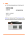
12: Reading
64
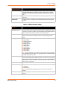
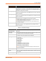
Data Reading Configuration _________________________________________________ 65
To View Data Reading Settings ___________________________________________ 65
13: Action Settings
66
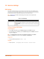
Alarms and Reports _______________________________________________________ 66
Actions Available for Alarms and Reports _______________________________________ 66
To Configure Terminal Block Power Alarm Settings ____________________________ 71
To Configure Barrel Connector Power Alarm Settings __________________________71
To Configure Input 1 and 2 Alarm Settings __________________________________ 72
To Configure Status Reports 1 and 2 Settings ________________________________ 72
To Configure Output 1 and 2 Alarm Settings _________________________________ 72
14: Tunnel and Modbus Settings
73
Tunnel Settings ___________________________________________________________ 73
Accept Mode __________________________________________________________ 73
To Configure Tunnel Accept Mode Settings __________________________________ 74
Modbus Settings __________________________________________________________ 75
To Configure Modbus Settings ____________________________________________ 75
Supported Modbus TCP/IP Functions and Registers ___________________________ 75
xSenso User Guide
5
15: Services Settings
77
DNS Settings _____________________________________________________________ 77
To View or Configure DNS Settings: _______________________________________ 77
FTP Settings _____________________________________________________________ 78
To Configure FTP Settings _______________________________________________78
Syslog Settings ___________________________________________________________ 78
To View or Configure Syslog Settings: ______________________________________ 79
HTTP Settings ____________________________________________________________ 79
To Configure HTTP Settings _____________________________________________ 80
To Configure HTTP Authentication _________________________________________ 81
RSS Settings _____________________________________________________________ 81
To Configure RSS Settings ______________________________________________ 82
SNMP Settings ___________________________________________________________ 82
To Configure SNMP Settings _____________________________________________ 83
SMTP Settings ___________________________________________________________ 83
To Configure SMTP Network Stack Settings _________________________________ 84
16: Security Settings
85
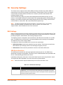
SSH Settings _____________________________________________________________ 85
SSH Server Host Keys __________________________________________________ 85
SSH Client Known Hosts ________________________________________________ 86
SSH Server Authorized Users ____________________________________________ 86
SSH Client Users ______________________________________________________ 87
To Configure SSH Settings ______________________________________________ 88
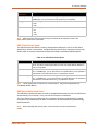
SSL Settings _____________________________________________________________ 88
Certificate and Key Generation ___________________________________________ 89
To Create a New Credential ______________________________________________ 89
Certificate Upload Settings _______________________________________________90
To Configure an Existing SSL Credential ____________________________________ 90
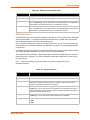
Trusted Authorities _____________________________________________________ 91
To Upload an Authority Certificate _________________________________________ 91
17: Maintenance and Diagnostics Settings
92
Filesystem Settings ________________________________________________________ 92
File Display ___________________________________________________________ 92
To Display Files _______________________________________________________ 92
File Modification _______________________________________________________ 93
File Transfer __________________________________________________________ 93
To Transfer or Modify Filesystem Files ______________________________________ 94
Protocol Stack Settings _____________________________________________________ 94
IP Settings ___________________________________________________________ 94
To Configure IP Network Stack Settings ____________________________________ 94
xSenso User Guide
6
ICMP Settings _________________________________________________________ 95
To Configure ICMP Network Stack Settings __________________________________ 95
ARP Settings _________________________________________________________ 95
To Configure ARP Network Stack Settings __________________________________ 95
SMTP Settings ________________________________________________________ 96
To Configure ARP Network Stack Settings __________________________________ 96
Diagnostics ______________________________________________________________ 96
Hardware ____________________________________________________________ 96
To View Hardware Information ____________________________________________ 96
IP Sockets ___________________________________________________________ 97
To View the List of IP Sockets ____________________________________________ 97
Ping ________________________________________________________________ 97
To Ping a Remote Host _________________________________________________ 97
Traceroute ___________________________________________________________ 98
To Perform a Traceroute ________________________________________________ 98
Log _________________________________________________________________ 98
To Configure the Diagnostic Log Output ____________________________________ 98
Memory ______________________________________________________________ 99
To View Memory Usage _________________________________________________ 99
Processes ____________________________________________________________ 99
To View Process Information _____________________________________________ 99
Threads ________________________________________________________________ 100
To View Thread Information _____________________________________________ 100
Clock __________________________________________________________________ 100
To Configure the Clock _________________________________________________ 101
System Settings _________________________________________________________ 101
To Reboot or Restore Factory Defaults ____________________________________ 101
Discovery and Query Port __________________________________________________ 102
To Configure Discovery ________________________________________________ 102
18: Advanced Settings
103
Email Settings ___________________________________________________________ 103
To View, Configure and Send Email _______________________________________ 103
Command Line Interface Settings ____________________________________________ 104
Basic CLI Settings ____________________________________________________ 104
To View and Configure Basic CLI Settings __________________________________ 104
Telnet Settings _______________________________________________________ 105
To Configure Telnet Settings ____________________________________________ 105
SSH Settings ________________________________________________________ 105
To Configure SSH Settings _____________________________________________ 106
XML Settings ____________________________________________________________ 106
XML: Export Configuration ______________________________________________106
To Export Configuration in XML Format ____________________________________ 107
xSenso User Guide
7
XML: Export Status ____________________________________________________ 107
To Export in XML Format _______________________________________________ 107
XML: Import Configuration ______________________________________________108
Import Configuration from External File ____________________________________ 108
Import Configuration from the Filesystem ___________________________________ 108
To Import Configuration in XML Format ____________________________________ 108
19: Security in Detail
109
Public Key Infrastructure ___________________________________________________ 109
TLS (SSL) ______________________________________________________________ 109
Digital Certificates ________________________________________________________ 109
Trusted Authorities _______________________________________________________ 109
Obtaining Certificates _____________________________________________________ 110
Self-Signed Certificates ____________________________________________________ 110
Certificate Formats _______________________________________________________ 110
OpenSSL _______________________________________________________________ 110
Steel Belted RADIUS _____________________________________________________ 111
Free RADIUS ___________________________________________________________ 111
20: Updating Firmware
112
Obtaining Firmware _______________________________________________________ 112
Loading New Firmware through Web Manager _________________________________ 112
To upload new firmware: ______________________________________________112
Loading New Firmware through FTP _________________________________________ 113
21: Branding the xSenso
114
Web Manager Customization _______________________________________________ 114
Short and Long Name Customization _________________________________________ 115
To Customize Short or Long Names ______________________________________ 115
xSenso User Guide
8
Appendix A: Technical Specifications
116
Analog Inputs ________________________________________________________ 116
Analog Outputs _______________________________________________________ 116
Relay Ports __________________________________________________________ 116
Architecture _________________________________________________________ 117
Network Interface _____________________________________________________ 117
Management _________________________________________________________ 117
Security _____________________________________________________________ 117
DAQ _______________________________________________________________ 118
Software ____________________________________________________________ 118
Power* _____________________________________________________________ 118
Environmental ________________________________________________________ 118
Physical Characteristics ________________________________________________ 118
Appendix B: Technical Support
119
Appendix C: Binary to Hexadecimal Conversions
120
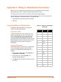
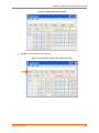
Converting Binary to Hexadecimal ___________________________________________ 120
Conversion Table _____________________________________________________ 120
Scientific Calculator ___________________________________________________ 120
Appendix D: Compliance
122
Appendix E: USB-CDC-ACM Device Driver File
for Windows Hosts
124
xSenso User Guide
9
List of Figures
Figure 2-1 Sample xSenso Configuration ______________________________________________ 16
Figure 2-2 Sample Applications _____________________________________________________ 17
Figure 2-3 xSenso Wiring Diagram ___________________________________________________ 19
Figure 2-4 xSenso Product Label ____________________________________________________ 21
Figure 3-1 xSenso 2100 Isolation Block Diagram ________________________________________ 23
Figure 3-2 xSenso , Front View______________________________________________________ 23
Figure 3-3 xSenso Top/Front View __________________________________________________ 24
Figure 3-6 xSenso, Side View_______________________________________________________ 26
Figure 3-7 xSenso Bottom/Back Panel View ___________________________________________ 26
Figure 4-1 xSenso 21A2 Isolation Block Diagram________________________________________ 29
Figure 4-2 xSenso 21A2, Front View _________________________________________________ 30
Figure 4-3 xSenso 21A2 Top/Front View ______________________________________________ 30
Figure 4-6 xSenso, Side Views ______________________________________________________ 32
Figure 4-7 xSenso Bottom/Back Panel View ___________________________________________ 33
Figure 5-1 xSenso 21R2 Isolation Block Diagram _______________________________________ 35
Figure 5-2 xSenso 21R2, Front View _________________________________________________ 36
Figure 5-3 xSenso 21R2 Top/Front View ______________________________________________ 36
Figure 5-6 xSenso, Side Views ______________________________________________________ 38
Figure 5-7 xSenso Bottom/Back Panel View ___________________________________________ 39
Figure 7-1 xSenso Home Pages _____________________________________________________ 43
Figure 7-2 Device Status Pages _____________________________________________________ 44
Figure 7-4 Live Reading vs. Configuration Pages________________________________________ 46
Figure 7-5 Components of the Web Manager Page ______________________________________ 47
Figure 9-1 Analog Inputs 1 and 2 for xSenso ___________________________________________ 53
Figure 10-1 Charting Options in the Chart Tab by xSenso Model ___________________________ 59
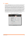
Figure 11-1 xSenso 2100 Logging Tab________________________________________________ 61
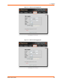
Figure 11-2 xSenso 21A2 Logging Tab _______________________________________________62
Figure 11-3 xSenso 21R2 Logging Tab _______________________________________________62
Figure 12-1 xSenso 2100 Reading Tab _______________________________________________64
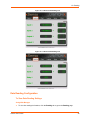
Figure 12-2 xSenso 21A2 Reading Tab _______________________________________________65
Figure 12-3 xSenso 21R2 Reading Tab _______________________________________________65
Figure 20-1 Uploading New Firmware _______________________________________________ 112
xSenso User Guide
10
List of Tables
Table 3-4 Analog Input LEDs _______________________________________________________ 24
Table 3-5 Ethernet LEDs __________________________________________________________ 25
Table 4-4 Analog Input and Analog Output LEDs _______________________________________ 31
Table 4-5 Ethernet LEDs __________________________________________________________ 31
Table 5-4 Analog Input and Relay Output LEDs ________________________________________ 37
Table 5-5 Ethernet LEDs __________________________________________________________ 37
Table 7-3 Comparing xSenso Home Page and Device Status Page Information _______________ 45
Table 8-1 Network Interface Settings _________________________________________________ 50
Table 8-2 Network 1 (eth0) Link Settings ______________________________________________ 52
Table 9-2 xSenso DAQ Command ___________________________________________________ 53
Table 9-3 DAQ Settings ___________________________________________________________ 54
Table 9-4 Analog Input Settings _____________________________________________________ 55
Table 9-5 Analog Output Settings ___________________________________________________ 56
Table 9-6 Relay Output Settings ____________________________________________________ 57
Table 10-2 Data Chart Settings _____________________________________________________ 60
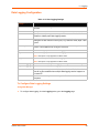
Table 11-4 Data Logging Settings ___________________________________________________ 63
Table 13-1 xSenso Alarms and Reports ______________________________________________ 66
Table 13-2 Control Analog Output Settings ____________________________________________ 66
Table 13-3 Make Connection Settings ________________________________________________ 67
Table 13-4 Send Email Settings _____________________________________________________ 68
Table 13-5 FTP Put Settings _______________________________________________________ 69
Table 13-6 HTTP Post Settings _____________________________________________________ 70
Table 13-7 Control Relay Settings ___________________________________________________ 70
Table 13-8 SNMP Trap Settings ____________________________________________________ 71
Table 14-1 Tunnel Accept Mode Settings _____________________________________________ 73
Table 14-2 Modbus Settings _______________________________________________________ 75
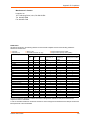
Table 14-3 0xxxx Read/Write Coils (Function Codes 1, 5 and 15) __________________________75
Table 14-4 3xxxx Read Only Registers (Function Codes 4 and 23) _________________________ 76
Table 14-5 4xxxx Read/Write Holding Registers (Function Codes 3, 16 and 23) _______________ 76
Table 15-1 DNS Settings __________________________________________________________ 77
Table 15-2 FTP Settings __________________________________________________________ 78
Table 15-3 Syslog Settings ________________________________________________________ 78
Table 15-4 HTTP Settings _________________________________________________________ 79
Table 15-5 HTTP Authentication Settings _____________________________________________ 81
Table 15-6 RSS Settings __________________________________________________________ 81
Table 15-7 SNMP Settings _________________________________________________________ 82
xSenso User Guide
11
Table 15-8 SMTP Network Stack Settings _____________________________________________ 83
Table 16-1 SSH Server Host Keys ___________________________________________________ 85
Table 16-2 SSH Client Known Hosts _________________________________________________ 86
Table 16-3 SSH Server Authorized Users _____________________________________________ 87
Table 16-4 SSH Client Users _______________________________________________________ 87
Table 16-5 Certificate and Key Generation Settings _____________________________________ 89
Table 16-6 Upload Certificate Settings _______________________________________________90
Table 16-7 Trusted Authority Settings ________________________________________________ 91
Table 17-1 File Display Settings ____________________________________________________ 92
Table 17-2 File Modification Settings _________________________________________________ 93
Table 17-3 File Transfer Settings ____________________________________________________ 93
Table 17-4 IP Network Stack Settings ________________________________________________ 94
Table 17-5 ICMP Network Stack Settings _____________________________________________ 95
Table 17-6 ARP Network Stack Settings ______________________________________________ 95
Table 17-7 SMTP Settings _________________________________________________________ 96
Table 17-8 Ping Settings __________________________________________________________ 97
Table 17-9 Traceroute Settings _____________________________________________________ 98
Table 17-10 Log Settings __________________________________________________________ 98
Table 17-11 Clock Settings _______________________________________________________ 100
Table 17-12 System Settings ______________________________________________________ 101
Table 17-13 Discovery Settings ____________________________________________________ 102
Table 18-1 Email Configuration ____________________________________________________ 103
Table 18-2 CLI Configuration Settings _______________________________________________ 104
Table 18-3 Telnet Settings _______________________________________________________ 105
Table 18-4 SSH Settings _________________________________________________________ 105
Table 18-5 XML Exporting Configuration _____________________________________________ 106
Table 18-6 Exporting Status _______________________________________________________ 107
Table 18-7 Import Configuration from Filesystem Settings _______________________________ 108
Table 21-1 Short and Long Name Settings ___________________________________________ 115
xSenso User Guide
12
1:
Using This Guide
Purpose and Audience
This guide provides the information needed to configure, use, and update the xSenso. It is
intended for software developers and system integrators who are installing this product into their
designs.
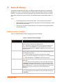
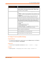
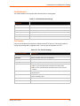
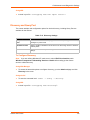
Summary of Chapters
The remaining chapters in this guide include:
Chapter
Description
2: Introduction
Main features of the product and the protocols it supports.
Includes technical specifications.
3: Installation of xSenso
Instructions for installing the xSenso 2100.
4: Installation of xSenso 21A2
Instructions for installing the xSenso 21A2.
5: Installation of xSenso 21R2
Instructions for installing the xSenso 21R2.
6: Using DeviceInstaller
Instructions for viewing the current configuration using
DeviceInstaller.
7: Configuration Using Web Manager
Instructions for accessing Web Manager and using it to configure
settings for the device.
8: Network Settings
Instructions for configuring network settings.
9: Analog Input, Output and Relay
Settings
Instructions for configuring analog and relay settings.
10: Chart
Instructions for viewing and configuring live analog chart data on
the Chart page.
11: Logging
Instructions for running and configuring live data logs on the
Logging page.
12: Reading
Instructions for reading live analog data on the Reading page.
13: Action Settings
Instructions for configuring action for reports and alarms settings.
14: Tunnel and Modbus Settings
Instructions for configuring modbus and tunnel settings.
15: Services Settings
Instructions for configuring DNS, FTP, HTTP and Syslog settings.
16: Security Settings
Instructions for configuring SSL security settings.
17: Maintenance and Diagnostics
Settings
Instructions to maintain the , view statistics, files, and diagnose
problems.
18: Advanced Settings
Instructions for configuring email, CLI and XML settings.
19: Security in Detail
Provides additional information on security settings available.
20: Updating Firmware
Instructions for obtaining the latest firmware and updating the .
21: Branding the xSenso
Instructions on how to brand your device.
Appendix A: Technical Specifications
Technical specifications for the device.
Appendix B: Technical Support
Instructions for contacting Lantronix Technical Support.
xSenso User Guide
13
1: Using This Guide
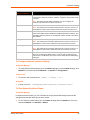
Chapter (continued)
Description
Appendix C: Binary to Hexadecimal
Conversions
Instructions for converting binary values to hexadecimals.
Appendix D: Compliance
Lantronix compliance information.
Appendix E: USB-CDC-ACM Device
Driver File for Windows Hosts
Information about the device driver file for windows host.
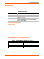
Additional Documentation
Visit the Lantronix Web site at www.lantronix.com/support/documentation for the latest
documentation and the following additional documentation.
Document
Description
xSenso Command Reference
Instructions for accessing Command Mode (the command line
interface) using a Telnet connection, SSH connection or through the
USB port. Detailed information about the commands. Also provides
details for XML configuration and status.
xSenso Quick Start Guide
Instructions for getting the xSenso up and running.
DeviceInstaller Online Help
Instructions for using the Lantronix Windows-based utility to locate the
xSenso and to view its current settings.
xSenso User Guide
14
2:
Introduction
xSenso is a compact DIN-rail or wall mount solution that enables sensors with analog outputs
(voltage or current) to easily and transparently send real-time data to any node on the network or
over the Internet. xSenso is an ideal solution for remote monitoring and data logging of critical
events in process control and automation applications. With its low port density, xSenso can be
affordably installed in dispersed locations. In applications where analog sensors and controllers
are used, xSenso can be configured to send alarms via emails or text messages when readings
are outside predefined ranges. These alarms allow control engineers to take immediate corrective
action when certain thresholds are met. Its embedded web server makes it possible to monitor the
input readings, chart or log the data using browsers on computers, smartphones, and tablets from
anywhere in the world.
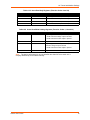
There are three Lantronix xSenso device servers:
xSenso 2100 with two analog inputs (part number XSO210000-01-S)
xSenso 21A2 with two analog inputs and two analog output (part number XSO21A200-01-S)
xSenso 21R2 with two analog inputs and two relay outputs (part number XSO21R200-01-S)
Key Features
Power Supply: 9-30 VDC input voltage (1 terminal screw block and 1 locking barrel jack,
where when both are used, may operate as redundancy and failover)
Ethernet: 1 Port Ethernet 10Base-T or 100Base-TX (auto-sensing for speed, duplex and
cross-over CAT5 cable)
Analog Inputs (All Models): 2 configurable analog inputs with available ranges: ±100mV,
±1V, ±10V or ±20mA
Analog Outputs (xSenso 21A2): 2 configurable isolated analog outputs with available ranges:
0-10V, 0-20mA
Relay Outputs (xSenso 21R2): 2 independently isolated mechanical form-C relays
Wireless:USB Ports: One 2.0 full speed USB port for device management and configuration
Temperature Range: Storage and operating temperature between -40° to +85°C
Note:
UL-certified operating temperature is -40° to +75°C
xSenso User Guide
15
2: Introduction
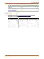
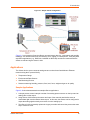
Figure 2-1 Sample xSenso Configuration
Figure 2-1 is an example of how the xSenso can send sensor data (e.g., temperature and humidity
readings), over shared networks or the internet to a PC, laptop, or a smart phone. Third party data
acquisition applications (e.g., DASYLab, LabVIEW or MATLAB) can also be interfaced with the
xSenso to read and log the sensor’s data.
Applications
The xSenso device server connects analog sensors such as those listed below to Ethernet
networks using the IP protocol family.
Temperature Gauge
Environmental Data Sensors
Gas Monitoring Devices
Sensors measuring humidity, pressure, flow, level, force, weight and gas or air quality
Sample Applications
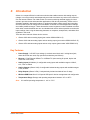
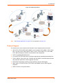
Figure 2-2 below demonstrates three sample xSenso applications:
1. A simple process control example consists of an analog pressure sensor on the input and an
analog valve on the output.
2. Using xSenso 21A2 between the sensor and input of the controller would allow users to
extract data right over the xSenso ethernet port. In this case, the xSenso can be configured to
output the analog signals exactly as receives it on the analog input.
3. The xSenso 21A2 can actually replace the Legacy controller and control the process the exact
way it used to be done.
xSenso User Guide
16
2: Introduction
Figure 2-2 Sample Applications
3
1
2
Note:
See Sample Applications on page 16 for an explanation of Figure 2-2.
Protocol Support
The xSenso device server contains a full-featured IP stack. Supported protocols include:
ARP, HTTP, HTTPS, SMTP AUTH, SNMP v1/v2c/v3, Modbus TCP, UDP/IP, TCP/IP, SSH,
SSL, TLS, RSS, UPnP, ICMP, BOOTP, DHCP, Auto IP, Telnet, SNTP, FTP, FTPS, DNS,
TFTP, XML and Syslog for network communications and management.
TFTP for uploading/downloading files.
FTP and HTTP/HTTPS web server for firmware upgrades and uploading/downloading files.
TCP/IP, UDP/IP, Telnet, SSH, SSL, TCP AES and UDP AES for command/response based
data acquisition application or alarm triggered connection
HTTP/HTTPS web based monitoring of input readings, chart and data logging
SMTP AUTH, HTTP/HTTPS Post, FTP/FTPS Put and SNMP Traps for alarm triggered
notification
SNTP for device clock synchronization
xSenso User Guide
17
2: Introduction
Troubleshooting Capabilities
The xSenso offers a comprehensive diagnostic toolset that lets you troubleshoot problems quickly
and easily. Available from the CLI or Web Manager, the diagnostic tools let you:
View memory and IP socket information.
Perform ping and traceroute operations.
Conduct forward or reverse DNS lookup operations.
View all processes currently running on the xSenso, including CPU utilization.
View system log messages.
Configuration Methods
After installation, the xSenso requires configuration. For the unit to operate correctly on a network,
it must have a unique IP address on the network. There are four basic methods for logging into the
xSenso and assigning IP addresses and other configurable settings:
Web Manager: View and configure all settings easily through a web browser using the
Lantronix Web Manager. (See “Configuration Using Web Manager” on page 42.)
DeviceInstaller: Configure the IP address and related settings and view current settings on
the xSenso using a Graphical User Interface (GUI) on a PC attached to a network. You will
need the latest version of DeviceInstaller. (See “Using DeviceInstaller” on page 40.)
Command Mode: There are two methods for accessing Command Mode (CLI): making a
Telnet or SSH connection, or connecting a PC or other host running a terminal emulation
program to the unit’s USB port. (See Configuration Using the MGMT (USB) Port below and the
xSenso Command Reference Guide for instructions and available commands.)
XML: The xSenso supports XML-based configuration and setup records that make device
configuration transparent to users and administrators. XML is easily editable with a standard
text or XML editor. (See the xSenso Command Reference Guide for instructions and
commands.)
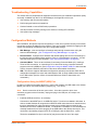
Configuration Using the MGMT (USB) Port
In order to configure and manage the device, connect the computer via USB cable to the xSenso
MGMT port and run a terminal emulation program (e.g., Tera Term).
Note: Device connection will be lost upon reboot. Close the connection (also close
emulation program terminal if needed), unplug and plug in the USB port, and reopen the
connection.
1. Install the USB device driver, as necessary.
Connection to the MGMT port is via USB-CDC-ACM. This driver is available in Windows. In
order to enable Windows to recognize the USB-CDC-ACM connection to the Lantronix device,
the driver installation file referenced below needs to be provided when prompted by the
Windows Device Driver Installation Wizard. For Windows 7 installation, it is recommended to
manually install the driver before plugging in the USB cable to the xSenso device port. This
can be done by installing a legacy driver for a COM port, with the Have Disk... option.
The device installation file (linux-cdc-acm.inf) may be accessed in one of two ways:
xSenso User Guide
18
2: Introduction
a. DeviceInstaller installation directory (typically at c:\Program File\Lantronix\Device
Installer\4.3).
b. Follow the instructions inAppendix E: USB-CDC-ACM Device Driver File for Windows
Hosts to create the .inf file and follow the windows driver installation steps as outlined
above.
2. Connect the USB cable to the MGMT (USB) port of the xSenso device.
3. Connect the USB cable from the xSenso to the USB port on your computer.
4. Apply power. If drivers are installed, a virtual com port will be created on the computer.
5. Launch an emulation program terminal (e.g., Tera Term) and select the virtual com port.
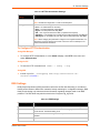
6. Open up the virtual com port. The serial setting should be 9600, 8, none, and 1.
7. Click OK.
8. Press Enter in the terminal window. You will be prompted to login.
9. Login to the xSenso to configure it. The default login and password:
-
User Name: admin
-
Password: PASS
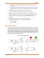
xSenso Wiring Example
In Figure 2-3 below, there are two sensors connected to the inputs of the xSenso. One is the
temperature sensor and the other is the humidity sensor. In this example, Relay 1 is associated
with the temperature sensor and Relay 2 with the humidity sensor. In Relay 1, the Normally Open
(NO) pin allows the green light to stay on under normal operations. Once the Normally Closed
(NC) pin is activated, the green light will be turned off and the red light will be turned on indicating
an alarm condition. The threshhold ranges can be defined within the xSenso web interface. In
Relay 2, a buzzer is connected to Normally Open (NO) pin and once the alarm condition is met,
the relay will be closed and the buzzer will sound.
Figure 2-3 xSenso Wiring Diagram
xSenso User Guide
19
2: Introduction
Addresses and Port Numbers
Hardware Address
The hardware address is also referred to as the Ethernet address, physical address, or MAC
address. Sample hardware address:
00---14-1B-18
00:::14:1B:18
IP Address
Every device connected to an IP network must have a unique IP address. This address references
the specific unit.
Port Numbers
Every TCP connection and every UDP datagram is defined by a destination and source IP
address, and a destination and source port number. For example, a Telnet server commonly uses
TCP port number 23.
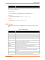
The following is a list of the default server port numbers running on the xSenso:
TCP Port 22: SSH Server (Command Mode configuration)
TCP Port 23: Telnet Server (Command Mode configuration)
TCP Port 80: HTTP (Web Manager configuration)
TCP Port 21: FTP
UDP Port 30718: LDP (Lantronix Discovery Protocol) port
TCP/UDP Port 10001: Tunnel 1 (see note below)
UDP Port 1900 and TCP Port 30179: UPnP
Note: Additional TCP/UDP ports and tunnels will be available, depending on the product
type. The default numbering of each additional TCP/UDP port and corresponding tunnel
will increase sequentially (i.e., TCP/UDP Port 1000X: Tunnel X).
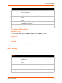
Product Information Label
The product information label on the unit contains the
following information about the specific unit:
Bar code
Product Revision
Part Number
Serial Number (MAC Address)
Manufacturing Date Code
xSenso User Guide
Note: The hardware address on the
label is also the product serial number.
The hardware address on the label is the
address for the Ethernet (eth0) interface.
20
2: Introduction
Figure 2-4 xSenso Product Label
Bar Code
Serial Number
Part Number
Revision
Manufacturing
Date Code
Country of Origin
& Manufacture
xSenso User Guide
21
3:
Installation of xSenso
This chapter describes how to install the xSenso analog device server. It contains the following
sections:
Package Contents
User-Supplied Items
Hardware Components
Installing the xSenso
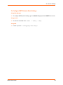
Package Contents
The xSenso package includes the following items:
One xSenso 2100 device
One 3-contact terminal block plug (screw type for power input port)
Two 6-contact terminal block plug (screw type for analog input ports)
Wall Mount Bracket
Four Rubber Feet
Quick Start Guide
User-Supplied Items
To complete your installation, you need the following items:
Analog devices and sensors that require network connectivity.
An available connection to your Ethernet network and an Ethernet cable.
A working AC power outlet if the unit will be powered from an AC power adapter.
A 9-30VDC power supply either terminal screw or barrel input (both may be used
simultaneously for power redundancy)
xSenso User Guide
22
3: Installation of xSenso
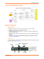
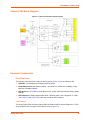
xSenso 2100 Isolation Block Diagram
Figure 3-1 xSenso 2100 Isolation Block Diagram
Hardware Components
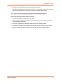
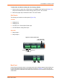
Front/Top Panel
The following components are located on the front panel (Figure 3-2) of the xSenso :
USB Port - for managing and configuring xSenso device.
RJ-45 Ethernet Port (with Ethernet LEDs) - can connect to an Ethernet (10 Mbps) or Fast
Ethernet (100 Mbps) network.
RST Button (the Reset Button inside the pin hole) - power cycles and restores factory default
settings.
LED Indicators (2 Analog Input LEDs, 2 Ethernet LEDs, and 1 Diagnostic “X” LED)
- see Table 3-4 and Table 3-5.
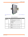
LED Indicators
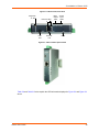
The Analog Input LEDs, the Ethernet LEDs, and the Diagnostic “X” LED are all located on the front
panel of the xSenso device (Figure 3-2).
Figure 3-2 xSenso , Front View
Analog
Input LEDs
Diagnostic
“X” LED
Ethernet LEDs
L
R
USB
Port
xSenso User Guide
Ethernet
Port
Reset Button
(pin hole)
Note: Though there appear
to be four analog input
LEDs located on the front
panel, only the two right
Input LEDs are supported in
xSenso .
23
3: Installation of xSenso
Figure 3-3 xSenso Top/Front View
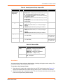
Table 3-4 and Table 3-5 below explain the LED information displayed in Figure 3-2 and Figure 3-3
above.
Table 3-4 Analog Input LEDs
LED
Color
ON
OFF
“X” on top of
xSenso device
(Diagnostic)
Orange
ORANGE ON - power present
No power
ORANGE Blink - during boot process after power cycle or
reset. Also blink patterns represent error conditions:
Analog Input 1
Green
or
Orange
Input Type (voltage or current)
Analog Input 2
Green
or
Orange
Input not utilized
GREEN represents 100mV, 1V or 10V input range is
selected
ORANGE represents 20mA input range is selected
Input Type (voltage or current)
xSenso User Guide
Loss of Redundant Power: one slow blink followed by
two fast blinks (repeat)
No Ethernet Link: two slow blinks followed by two fast
blinks (repeat)
No IP Address: three slow blinks followed by three fast
blinks (repeat)
Input not utilized
GREEN represents 100mV, 1V or 10V input range is
selected
ORANGE represents 20mA input range is selected
24
3: Installation of xSenso
Table 3-5 Ethernet LEDs
Ethernet LEDs
Description
Left (L)
GREEN ON - 100 Mbps link established
GREEN Blink - 100Mbps activity
AMBER ON - 10 Mbps link established
AMBER Blink - 10 Mbps activity
Right (R)
GREEN ON - Full duplex
OFF - Half duplex
Reset Button
You can reset the xSenso to factory default settings, including clearing the network settings. The
IP address, gateway, and netmask are set to 00s.
To reset the unit to factory defaults:
1. Place the end of a paper clip or similar object into the RST (reset) opening (see Figure 3-2)
and press and hold down micro switch during a power cycle for a minimum of 25 seconds.
2. Remove the paper clip to release the button. The unit will continue the boot process restoring
it back to the original factory default settings.
To reboot the unit without resetting the unit to factory defaults:
1. Place the end of a paper clip or similar object into the RST (reset) opening (see Figure 3-2)
and press and hold down micro switch during a power cycle for 3 to 5 seconds.
2. Remove the paper clip to release the button. The unit will reboot.
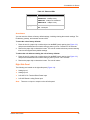
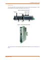
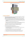
Right Side Panel
The following are located on the right side panel (Figure 3-6):
Analog Input 1
Analog Input 2
9-30 VDC 3 Pin Terminal Block Power Input
9-30 VDC Barrel Locking Power Input
Note:
There are no inputs or outputs on the left side panel.
xSenso User Guide
25
3: Installation of xSenso
Figure 3-6 xSenso, Side View
9-30 VDC Barrel
Locking Power Input
Excitation
Voltage Input
Current Input
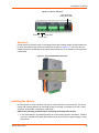
Back Panel
On the xSenso back panel, there is a mounting bracket with a sliding orange clip which allows you
to mount and dismount the device from a DIN rail, as shown in Figure 3-3. There are also four
rubber feet that can be attached to the bottom-side of the device, if the xSenso is to be placed on
a flat surface.
Figure 3-7 xSenso Bottom/Back Panel View
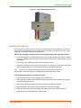
Installing the xSenso
Be sure to place or mount the device securely on a flat horizontal or vertical surface. The device
comes with mounting brackets for mounting the device vertically, for example on a wall. If using
AC power, avoid outlets controlled by a wall switch.
Observe the following guidelines when connecting the analog input devices:
It is recommended to use twisted-pair wires to connect analog sensors and xSenso. If EMC is
a concern, shielded wires and/or ferrite bead may be used to improve signal integrity in noisy
environment.
xSenso User Guide
26
3: Installation of xSenso
Connect your RJ-45 Ethernet cable to the RJ-45 port of the unit.
The xSenso supports a power range of 9 to 30 VDC. You can power up the device with barrelpower connector and/or the 3 pin terminal connector for backup power supply.
Note: As soon as you plug the device into power, the device/sensors powers up
automatically, the self-test begins, and LEDs would indicate the device's status
Perform the following steps to install your device:
1. Connect analog xSenso to the analog input ports.
2. Hook up power excitations from xSenso to analog sensors/devices if needed and if xSenso
meets the power requirement.
3. Connect a RJ-45 Ethernet cable between the unit and your Ethernet network.
4. Connect the 9-30 VDC to the terminal block, barrel jack or both, and power on the xSenso.
5. Power up analog input devices/sensors if they are not powered by xSenso excitation.
xSenso User Guide
27
4:
Installation of xSenso 21A2
This chapter describes how to install the xSenso 21A2 device server. It contains the following
sections:
Package Contents
User-Supplied Items
Hardware Components
Hardware Components
Installing the xSenso
Package Contents
The xSenso package includes the following items:
One xSenso 21A2 device
Three 3-contact Terminal Block Plug - screw type for Power Input Port and Analog Output
Ports.
Two 6-contact Terminal Block Plug - screw type for Analog Input Ports
Wall Mount Bracket
Four Rubber Feet
Quick Start Guide
User-Supplied Items
To complete your installation, you need the following items:
Analog devices and sensors that require network connectivity.
Devices to be controlled by analog output.
An available connection to your Ethernet network and an Ethernet cable.
A working AC power outlet if the unit will be powered from an AC power adapter.
A 9-30VDC power supply either terminal screw or barrel input (both may be used
simultaneously for power redundancy)
xSenso User Guide
28
4: Installation of xSenso 21A2
xSenso 21A2 Isolation Block Diagram
Figure 4-1 xSenso 21A2 Isolation Block Diagram
Hardware Components
Front/Top Panel
The following components are located on the front panel (Figure 4-2) of the xSenso 21A2:
USB Port - for managing and configuring xSenso device.
RJ-45 Ethernet Port (with Ethernet LEDs) - can connect to an Ethernet (10 Mbps) or Fast
Ethernet (100 Mbps) network.
RST Button (the Reset Button inside the pin hole) - power cycles and restores factory default
settings.
LED Indicators (4 Analog Input/Output LEDs, 2 Ethernet LEDs, and 1 Diagnostic “X” LED)
- see Table 4-4 and Table 4-5.
xSenso User Guide
29
4: Installation of xSenso 21A2
LED Indicators
The Analog Input LEDs, the Analog Output LEDs, the Ethernet LEDs, and the Diagnostic “X” LED
are all located on the front panel of the xSenso device (Figure 4-3).
Figure 4-2 xSenso 21A2, Front View
Diagnostic
“X” LED
Ethernet LEDs
L
R
USB
Port
Ethernet
Port
Analog Analog
Output Input
LEDs
LEDs
Reset
Figure 4-3 xSenso 21A2 Top/Front View
Table 4-4 and Table 4-5 below explain the LED information displayed in Figure 4-2 and Figure 4-3
above.
xSenso User Guide
30
4: Installation of xSenso 21A2
Table 4-4 Analog Input and Analog Output LEDs
LED
Color
“X” on top of
xSenso device
(Diagnostic)
Orange
ON
OFF
ORANGE ON - power present
No power
ORANGE Blink - during boot process after power cycle or
reset. Also blink patterns represent error conditions:
Analog Input 1
Green
or
Orange
Input Type (voltage or current)
Analog Input 2
Green
or
Orange
Analog Output 2
Green
or
Orange
Green
or
Orange
Output not utlized.
GREEN represents 0-10V output range is selected
ORANGE represents 20mA output range is selected
Output Type (voltage or current)
Input not utilized
GREEN represents 100mV, 1V or 10V input range is
selected
ORANGE represents 20mA input range is selected
Output Type (voltage or current)
Input not utilized
GREEN represents 100mV, 1V or 10V input range is
selected
ORANGE represents 20mA input range is selected
Input Type (voltage or current)
Analog Output 1
Loss of Redundant Power: one slow blink followed by
two fast blinks (repeat)
No Ethernet Link: two slow blinks followed by two fast
blinks (repeat)
No IP Address: three slow blinks followed by three fast
blinks (repeat)
Output not utlized.
GREEN represents 0-10V output range is selected
ORANGE represents 20mA output range is selected
Table 4-5 Ethernet LEDs
Ethernet LEDs
Description
Left (L)
GREEN ON - 100 Mbps link established
GREEN Blink - 100Mbps activity
AMBER ON - 10 Mbps link established
AMBER Blink - 10 Mbps activity
Right (R)
GREEN ON - Full duplex
OFF - Half duplex
Reset Button
You can reset the xSenso to factory default settings, including clearing the network settings. The
IP address, gateway, and netmask are set to 00s.
To reset the unit to factory defaults:
1. Place the end of a paper clip or similar object into the RST (reset) opening (see Figure 4-2)
and press and hold down micro switch during a power cycle for a minimum of 25 seconds.
2. Remove the paper clip to release the button. The unit will continue the boot process restoring
it back to the original factory default settings.
xSenso User Guide
31
4: Installation of xSenso 21A2
To reboot the unit without resetting the unit to factory defaults:
1. Place the end of a paper clip or similar object into the RST (reset) opening (see Figure 4-2)
and press and hold down micro switch during a power cycle for 3 to 5 seconds.
2. Remove the paper clip to release the button. The unit will reboot.
Side Panels
The following are located on the side panels (Figure 4-6):
Right Side
Analog Input 1
Analog Input 2
9-30 VDC 3 Pin Terminal Block Power Input
9-30 VDC Barrel Locking Power Input
Left Side
Analog Output 1
Analog Output 2
Figure 4-6 xSenso, Side Views
9-30 VDC Barrel
Locking Power Input
Excitation
Voltage Input
Current Input
Analog
Analog
Output 1 Output 2
Back Panel
On the xSenso back panel, there is a mounting bracket with a sliding orange clip which allows you
to mount and dismount the device from a DIN rail, as shown in Figure 4-7. There are also four
rubber feet that can be attached to the bottom-side of the device, if the xSenso is to be placed on
a flat surface.
xSenso User Guide
32
4: Installation of xSenso 21A2
Figure 4-7 xSenso Bottom/Back Panel View
Installing the xSenso
Be sure to place or mount the device securely on a flat horizontal or vertical surface. The device
comes with mounting brackets for mounting the device vertically, for example on a wall. If using
AC power, avoid outlets controlled by a wall switch.
Observe the following guidelines when connecting the analog input and output devices:
It is recommended to use twisted-pair wires to connect analog sensors and xSenso. If EMC is
a concern, shielded wires and/or ferrite bead may be used to improve signal integrity in noisy
environment.
Connect your RJ-45 Ethernet cable to the RJ-45 port of the unit.
The xSenso supports a power range of 9 to 30 VDC. You can power up the device with barrelpower connector and/or the 3 pin terminal connector for backup power supply.
Note: As soon as you plug the device into power, the device/sensors powers up
automatically, the self-test begins, and LEDs would indicate the device's status
Perform the following steps to install your device:
1. Connect analog devices to the analog input and output ports.
2. Hook up power excitations from xSenso to analog sensors/devices if needed and if xSenso
meets the power requirement.
3. Connect a RJ-45 Ethernet cable between the unit and your Ethernet network.
4. Plug the xSenso into the power outlet by using the included power supply.
5. Power up analog input devices/sensors if they are not powered by xSenso excitation.
6. Power up devices to be controlled by analog output.
xSenso User Guide
33
5:
Installation of xSenso 21R2
This chapter describes how to install the xSenso 21R2 device server. It contains the following
sections:
Package Contents
User-Supplied Items
Hardware Components
Installing the xSenso
Package Contents
The xSenso package includes the following items:
One xSenso 21R2 device
Three 3-contact Terminal Block Plug - screw type for Power Input Port and Relay Output Ports
Two 6-contact Terminal Block Plug - screw type for Analog Input Ports
Wall Mount Bracket
Four Rubber Feet
Quick Start Guide
User-Supplied Items
To complete your installation, you need the following items:
Devices to be controlled by relay
Analog devices and sensors that require network connectivity.
An available connection to your Ethernet network and an Ethernet cable.
A working AC power outlet if the unit will be powered from an AC power adapter.
A 9-30VDC power supply either terminal screw or barrel input (both may be used
simultaneously for power redundancy)
xSenso User Guide
34
5: Installation of xSenso 21R2
xSenso 21R2 Block Diagram
Figure 5-1 xSenso 21R2 Isolation Block Diagram
Hardware Components
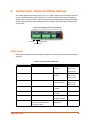
Front/Top Panel
The following components are located on the front panel (Figure 5-2) of the xSenso 21R2:
USB Port - for managing and configuring xSenso device.
RJ-45 Ethernet Port (with Ethernet LEDs) - can connect to an Ethernet (10 Mbps) or Fast
Ethernet (100 Mbps) network.
RST Button (the Reset Button inside the pin hole) - power cycles and restores factory default
settings.
LED Indicators (4 Analog Input/Output LEDs, 2 Ethernet LEDs, and 1 Diagnostic “X” LED)
- see Table 5-4 and Table 5-5 to learn how to read the LED indicators.
LED Indicators
The Analog Input LEDs, the Relay Output LEDs, the Ethernet LEDs, and the Diagnostic “X” LED
are all located on the front panel of the xSenso device (Figure 5-2).
xSenso User Guide
35
5: Installation of xSenso 21R2
Figure 5-2 xSenso 21R2, Front View
Diagnostic
“X” LED
Ethernet LEDs
L
R
USB
Port
Ethernet
Port
Relay Analog
Output Input
LEDs
LEDs
Reset
Figure 5-3 xSenso 21R2 Top/Front View
Table 5-4 and Table 5-5 below explain the LED information displayed in Figure 5-2 and Figure 5-3
above.
xSenso User Guide
36
5: Installation of xSenso 21R2
Table 5-4 Analog Input and Relay Output LEDs
LED
Color
“X” on top of
xSenso device
(Diagnostic)
Orange
ON
OFF
ORANGE ON - power present
No power
ORANGE Blink - during boot process after power cycle or
reset. Also blink patterns represent error conditions:
Analog Input 1
Green
or
Orange
Input Type (voltage or current)
Analog Input 2
Green
or
Orange
Loss of Redundant Power: one slow blink followed by
two fast blinks (repeat)
No Ethernet Link: two slow blinks followed by two fast
blinks (repeat)
No IP Address: three slow blinks followed by three fast
blinks (repeat)
GREEN represents 100mV, 1V or 10V input range is
selected
ORANGE represents 20mA input range is selected
Input Type (voltage or current)
Input not utilized
Input not utilized
GREEN represents 100mV, 1V or 10V input range is
selected
ORANGE represents 20mA input range is selected
Relay Output 1
Green
GREEN represents relay is turned on/energized.
(i.e. COM = NO)
OFF represents
relay is turned off
(i.e. COM = NC)
Relay Output 2
Green
GREEN represents relay is turned on/energized.
(i.e. COM = NO)
OFF represents
relay is turned off
(i.e. COM = NC)
Table 5-5 Ethernet LEDs
Ethernet LEDs
Description
Left (L)
GREEN ON - 100 Mbps link established
GREEN Blink - 100Mbps activity
AMBER ON - 10 Mbps link established
AMBER Blink - 10 Mbps activity
Right (R)
GREEN ON - Full duplex
OFF - Half duplex
Reset Button
You can reset the xSenso to factory default settings, including clearing the network settings. The
IP address, gateway, and netmask are set to 00s.
To reset the unit to factory defaults:
1. Place the end of a paper clip or similar object into the RST (reset) opening (see Figure 5-2)
and press and hold down micro switch during a power cycle for a minimum of 25 seconds.
2. Remove the paper clip to release the button. The unit will continue the boot process restoring
it back to the original factory default settings.
xSenso User Guide
37
5: Installation of xSenso 21R2
To reboot the unit without resetting the unit to factory defaults:
1. Place the end of a paper clip or similar object into the RST (reset) opening (see Figure 5-2)
and press and hold down micro switch during a power cycle for 3 to 5 seconds.
2. Remove the paper clip to release the button. The unit will reboot.
Side Panels
The following are located on the side panels (Figure 5-6):
Left Side
Analog Input 1
Analog Input 2
9-30 VDC 3 Pin Terminal Block Power Input
9-30 VDC Barrel Locking Power Input
Right Side
Relay Output 1
Relay Output 2
Figure 5-6 xSenso, Side Views
9-30 VDC Barrel
Locking Power Input
Excitation
Voltage Input
Current Input
Relay 1
Relay 2
Back Panel
On the xSenso back panel, there is a mounting bracket with a sliding orange clip which allows you
to mount and dismount the device from a DIN rail, as shown in Figure 5-7. There are also four
rubber feet that can be attached to the bottom-side of the device, if the xSenso is to be placed on
a flat surface.
xSenso User Guide
38
5: Installation of xSenso 21R2
Figure 5-7 xSenso Bottom/Back Panel View
Installing the xSenso
Be sure to place or mount the device securely on a flat horizontal or vertical surface. The device
comes with mounting brackets for mounting the device vertically, for example on a wall. If using
AC power, avoid outlets controlled by a wall switch.
Observe the following guidelines when connecting the analog input and output devices:
It is recommended to use twisted-pair wires to connect analog sensors and xSenso. If EMC is
a concern, shielded wires and/or ferrite bead may be used to improve signal integrity in noisy
environment.
Connect your RJ-45 Ethernet cable to the RJ-45 port of the unit.
The xSenso supports a power range of 9 to 30 VDC. You can power up the device with barrelpower connector and/or the 3 pin terminal connector for backup power supply.
Note: As soon as you plug the device into power, the device/sensors powers up
automatically, the self-test begins, and LEDs would indicate the device's status
Perform the following steps to install your device:
1. Connect analog devices to the analog input and relay output ports.
2. Hook up power excitations from xSenso to analog sensors/devices if needed and if xSenso
meets the power requirement.
3. Connect a RJ-45 Ethernet cable between the unit and your Ethernet network.
4. Plug the xSenso into the power outlet by using the included power supply.
5. Power up analog input devices/sensors if they are not powered by xSenso excitation.
6. Power up device to be controlled by relay or supply power to be controlled by relay.
xSenso User Guide
39
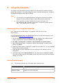
6:
Using DeviceInstaller
This chapter covers the steps for locating a xSenso unit and viewing its properties and device
details. DeviceInstaller is a free utility program provided by Lantronix that discovers, configures,
upgrades and manages Lantronix Device Servers.
Notes:
For instructions on using DeviceInstaller to configure the IP address and related
settings or for more advanced features, see the DeviceInstaller Online Help.
Auto IP generates a random IP address in the range of 169.254.0.1 to
169.254.255.254, with a netmask of 255.255.0.0, if no BOOTP or DHCP server is
found. These addresses are not routable.
Accessing xSenso Using DeviceInstaller
Note: Make note of the MAC address. It is needed to locate the xSenso using
DeviceInstaller.
To use the DeviceInstaller utility, first install the latest version from the downloads page on the
Lantronix web site www.lantronix.com/downloads.
1. Run the executable to start the installation process and respond to the installation wizard
prompts. (If prompted to select an installation type, select Typical.)
2. Click Start -> All Programs -> Lantronix -> DeviceInstaller 4.3 -> DeviceInstaller.
3. When DeviceInstaller starts, it will perform a network device search. To perform another
search, click Search.
4. Expand the xSenso folder by clicking the + symbol next to the folder icon. The list of available
Lantronix xSenso devices appears.
5. Select the xSenso unit by expanding its entry and clicking on its IP address to view its
configuration.
6. On the right page, click the Device Details tab. The current xSenso configuration appears.
This is only a subset of the full configuration; the full configuration may be accessed via Web
Manager, CLI or XML.
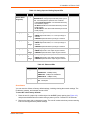
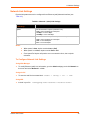
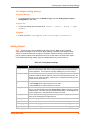
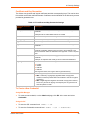
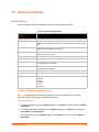
Device Detail Summary
Note:
The settings are Display Only in this table unless otherwise noted
Current Settings
Description
Name
Shows “xSenso 2100”, “xSenso 21A2” or “xSenso 21R2”.
DHCP Device Name
The name associated with the xSenso’s current IP address, if the IP
address was obtained dynamically.
xSenso User Guide
40
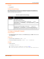
6: Using DeviceInstaller
Current Settings
Description
Group
Configurable field. Enter a group to categorize the xSenso. Double-click the
field, type in the value, and press Enter to complete. This group name is
local to this PC and is not visible on other PCs or laptops using
DeviceInstaller.
Comments
Configurable field. Enter comments for the xSenso. Double-click the field,
type in the value, and press Enter to complete. This description or comment
is local to this PC and is not visible on other PCs or laptops using
DeviceInstaller.
Device Family
Shows the xSensodevice family type as “xSenso”.
Short Name
Shows “xSenso 2100”, “xSenso 21A2” or “xSenso 21R2” by default.
Long Name
Shows Lantronix xSenso 2100”, “Lantronix xSenso 21A2” or “Lantronix
xSenso 21R2” by default.
Type
Shows the device type as “xSenso 2100 Series”””.
ID
Shows the xSenso ID embedded within the unit.
Hardware Address
Shows the xSenso hardware (MAC) address.
Firmware Version
Shows the firmware currently installed on the xSenso.
Extended Firmware Version Provides additional information on the firmware version.
Online Status
Shows the xSenso status as Online, Offline, Unreachable (the xSenso is on
a different subnet), or Busy (the xSenso is currently performing a task).
IP Address
Shows the xSenso current IP address. To change the IP address, click the
Assign IP button on the DeviceInstaller menu bar.
IP Address was Obtained
Appears “Dynamically” if the xSenso automatically received an IP address
(e.g., from DHCP). Appears “Statically” if the IP address was configured
manually.
If the IP address was assigned dynamically, the following fields appear:
Obtain via DHCP with values of True or False.
Obtain via BOOTP with values of True or False.
Subnet Mask
Shows the subnet mask specifying the network segment on which the
xSenso resides.
Gateway
Shows the IP address of the router of this network.
There is no default.
Number of Analog Inputs
Shows the number of analog inputs on the xSenso device.
Number of Analog Outputs
Shows the number of analog outputs on the xSenso device.
Note: This field only displays for xSenso 21A2 models.
Number of Relay Outputs
Shows the number of relay outputs on the xSenso device.
Note: This field only displays for xSenso 21R2 models.
Supports Configurable Pins Shows False, indicating configurable pins are not available on the xSenso.
Supports Email Triggers
Shows True, indicating email triggers are available on the xSenso .
Telnet Supported
Indicates whether Telnet is enabled on this xSenso.
Telnet Port
Shows the xSenso port for Telnet sessions.
Web Port
Shows the xSenso port for web sessions.
Firmware Upgradable
Shows True, indicating the xSenso firmware is upgradable as newer
versions become available.
xSenso User Guide
41
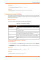
7:
Configuration Using Web Manager
This chapter describes how to configure xSenso using Web Manager, the Lantronix browserbased configuration tool. The unit’s configuration is stored in nonvolatile memory and is retained
without power. All changes take effect immediately, unless otherwise noted. It contains the
following sections:
Accessing Web Manager
Web Manager Components
Navigating Web Manager
Accessing Web Manager
Note: You can also access the Web Manager by selecting the Web Configuration tab on
the DeviceInstaller window.
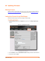
To access Web Manager, perform the following steps:
1. Open a standard web browser. Lantronix supports the latest version of Internet Explorer,
Mozilla Suite, Mozilla Firefox, Safari, Chrome or Opera.
Note: Lantronix recommends using the latest version of Chrome when viewing and
configuring the Chart tab/page.
2. Enter the IP address or hostname of the xSenso in the address bar. The IP address may have
been assigned manually using DeviceInstaller (see the xSenso Quick Start Guide) or
automatically by DHCP.
3. Enter your username and password.The factory-default username is “admin” and the
password is “PASS”. The xSenso Home page displays with a brief summary of current status
information about your xSenso device including product information, network settings and
analog status information.
xSenso User Guide
42
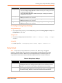
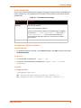
7: Configuration Using Web Manager
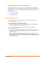
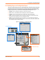
Figure 7-1 xSenso Home Pages
There are three xSenso models.
The Home page for each model is
identical except for these
differences:
1) The xSenso model can be
identified to the right of the
Product Type in the Home page.
2) xSenso 21A2 has two additional
output status fields.
3) xSenso 21R2 has two additional
relay status fields.
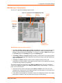
4. Click the Admin tab to get to the Admin > Device Status page. The Device Status web page
displays the same and more information than on the xSenso Home page: configuration,
network settings, analog status, tunneling settings, and product information.
xSenso User Guide
43
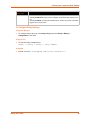
7: Configuration Using Web Manager
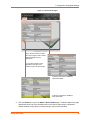
Figure 7-2 Device Status Pages
There are three
xSenso models. The
Device Status page for
each model is identical
except for these
differences:
1) The xSenso model
can be identified to the
right of the Product
Type in the Home
page.
2) xSenso 21A2 has
two additional output
status fields.
3) xSenso 21R2 has
two additional relay
status fields.
Note: The Logout button is available on any web page under the Setup and Admin TabPages when authentication is enabled (by default). Logging out of the web page would
force re-authentication to take place the next time the web page is accessed.
xSenso User Guide
44
7: Configuration Using Web Manager
xSenso Home and Device Status Pages
The xSenso Home page is the first page that appears after you log into Web Manager. The Device
Status page appears when you click Status in the Admin tab/page in Web Manager.
The xSenso Home page and the Device Status pages show overlapping information. For most
users, the xSenso Home page contains the basic product and status information necessary. For
advanced users, the Device Status page contains additional configuration information:
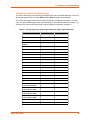
Table 7-3 Comparing xSenso Home Page and Device Status Page Information
Information Provided
xSenso Home Page
Device Status Page
Product Type
x
x
Firmware Version
x
x
Build Date
x
Serial Number/MAC
Address
x
x
Uptime
x
x
Permanent Config
x
Interface
x
Link
x
MAC Address
x
Hostname
x
x
IP Address
x
x
Default Gateway
x
x
Domain
x
Primary DNS
x
Secondary DNS
x
MTU
x
Input 1
x
x
Input 2
x
x
Output 1
(only for xSenso 21A2)
x
x
Output 2
(only for xSenso 21A2)
x
x
Relay 1
(only for xSenso 21R2)
x
x
Relay 2
(only for xSenso 21R2)
x
x
Tunnel 1
x
Tunnel 2
x
xSenso User Guide
45
7: Configuration Using Web Manager
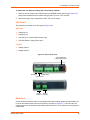
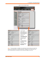
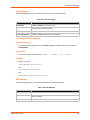
Live Reading Pages and Configuration Pages
There are five tabs that span the top of the Web Manager page. Beyond the xSenso Home page
accessed through the Home tab at the top left, you may access the other Web Manager pages
through the four other tabs. The Reading, Chart and Logging tab/pages provide live data on the
analog input signals and the Setup and Admin tab/pages provide configuration menus:
Reading: view live readings of analog input, output and relay data.
Chart: view live, customizable charts of analog input, output and relay data.
Logging: view and customize data logs of analog input, output and relay data.
Setup: access the configuration menu to the Action, Analog Input, Analog Output, Relay,
DAQ Format, Email, System and Tunnel configuration pages.
Admin: access the configuration menu to the Status, CLI, Clock, Diagnostics, Discovery,
DNS, Filesystem, FTP, HTTP, Modbus, Network, Protocol Stack, RSS, SMTP, SNMP, SSH,
SSL, Syslog and XML configuration pages.
Figure 7-4 Live Reading vs. Configuration Pages
Live Reading Pages
HOME PAGE
Configuration Pages
xSenso User Guide
46
7: Configuration Using Web Manager
Web Manager Components
The layout of a typical Web Manager page is below.
Figure 7-5 Components of the Web Manager Page
Items to
configure
Header
Links to
subpages
Logout
button
Tabs/Pages
Menu Bar
(only in the
Setup and
Admin tab/
pages)
Footer
Information
and Help Area
Web Manager pages have these sections:
The Home, Reading, Chart, Logging, Setup and Admin tabs at the top of the page provide
direct access to each Web Manager page of the same name. All the functionality in Web
Manager is divided between these tab/pages. For instance, clicking the Admin tab brings you
to the Admin page or the Reading tab to get to the Reading page.
The Reading, Chart and Logging tab/pages provide live sensor data. These pages together
with the xSenso Home page, are designed for users who are simply monitoring analog input,
output and relay data.
The Setup and Admin tab/pages contain several subpages allowing viewing and
configuration of various settings. These pages would be useful for an advanced user wishing
to view and modify xSenso configurations.
The menu bar appears at the left side of the Setup and Admin pages. The menu bar lists the
names of the subpages available in the Setup and Admin pages in Web Manager. To bring up a
page, click it in the menu bar.
Links near the top of many of the pages under Setup and Admin, such as the one in the
example above, enable you to link to additional pages. On some pages, you must also select
the item you are configuring, such as a tunnel.
In the middle of many pages, you can select or enter new configuration settings. Some pages
show status or statistics in this area rather than allow you to enter settings.
xSenso User Guide
47
7: Configuration Using Web Manager
At the bottom of most pages, the current configuration is displayed. In some cases, you can
reset or clear a setting.
The information or help area shows information or instructions associated with the page.
A Logout link is available at the upper right corner of every Setup and Admin page. In
Chrome or Safari, it is necessary to close out of the browser to completely logout. If
necessary, reopen the browser to log back in.
The footer appears at the very bottom of the page. It contains copyright information and a link
to the Lantronix home page.
Navigating Web Manager
The Web Manager provides an intuitive point-and-click interface. A menu bar on the left side of
each page provides links you can click to navigate from one page to another while the Reading,
Chart and Logging pages are accessed by tabs across the top of the page. Some pages are readonly, while others let you change configuration settings.
Note: There may be times when you must reboot the xSenso for the new configuration
settings to take effect. The chapters that follow indicate when a change requires a reboot.
Anytime you reboot the unit, this operation will take some time to complete. Please wait a
minimum of 10-20 seconds after rebooting the unit before attempting to make any
subsequent connections.
Web Manager Page
Description
See
Page
Status
Shows product information, network, analog status, and tunneling settings.
45
Action
Allows you to view and configure the actions for a specific alarm or report.
66
Analog Input
Allows you to view and configure analog input, shows current input status and 55
allows you to scale and modify display of both analog inputs.
Analog Output
Allows you to view and configure analog output, shows current output
statuses and allows you to modify display of analog outputs.
56
Charting
Shows data on a live chart and chart configuration options.
59
CLI
Shows Command Line Interface (CLI) statistics and lets you change the
current CLI configuration settings.
104
Clock
Allows you to view and configure the current date, time and time zone as it
displays in web manager.
100
DAQ Format
Allows you to change data response format in Tunnel and Action connect
applications.
53
Diagnostics
Lets you perform various diagnostic procedures.
96
Discovery
Allows you to view and modify the configuration and statistics for device
discovery.
102
DNS
Shows the current configuration of the DNS subsystem and the DNS cache.
77
Email
Shows email statistics and lets you clear the email log, configure email
settings, and send an email.
103
Filesystem
Shows file system statistics and lets you browse the file system to view a file, 92
create a file or directory, upload files using HTTP, copy a file, move a file, or
perform TFTP actions.
xSenso User Guide
48
7: Configuration Using Web Manager
Web Manager Page
(continued)
Description
See
Page
FTP
Shows statistics and lets you change the current configuration for the File
Transfer Protocol (FTP) server.
78
HTTP
Shows HyperText Transfer Protocol (HTTP) statistics and lets you change the 79
current configuration and authentication settings.
Logging
Shows analog input, output and relay information through a live log and
provides log file configuration options.
61
Modbus
Shows the current connection status of the Modubs servers listening on the
TCP ports and configure Modbus TCP server.
75
Network
Shows status and lets you configure the network interface.
50
Protocol Stack
Lets you perform lower level network stack-specific activities.
94
Query Port
Lets you change configuration settings for the query port.
96
Reading
Shows live analog input, output and relay reading information.
64
Relay
Allows you to view and configure relay output, shows current relay output
statuses and allows you to modify display of both relays.
57
RSS
Lets you change current Really Simple Syndication (RSS) settings.
81
SMTP
Shows and modify the current configuration of SMTP.
83
SNMP
Shows and modify the current configuration of SNMP.
82
SSH
Lets you change the configuration settings for SSH server host keys, SSH
server authorized users, SSH client known hosts, and SSH client users.
85
SSL
Lets you upload an existing certificate or create a new self-signed certificate.
88
Syslog
Lets you specify the severity of events to log and the server and ports to
which the syslog should be sent.
78
System
Lets you reboot device, restore factory defaults, upload new firmware, and
change the device long and short names.
101
Tunnel
Lets you change the current configuration settings for an incoming tunnel
connection.
73
XML
Lets you export XML configuration and status records, and import XML
configuration records.
106
xSenso User Guide
49
8:
Network Settings
The Network Settings show the status of the Ethernet interface/link and let you configure the
settings on the device. Interface settings are related to the configuration of the IP and related
protocols. Link settings are related to the physical link connection, which carries the IP traffic.
The xSenso contains one network interface. The Ethernet interface is also called interface 1 or
eth0.
Notes:
Some settings require a reboot to take effect. These settings are noted below.
Wait a minimum of 10-20 seconds after rebooting the unit before attempting to make
any subsequent connections.
The blue text in the XML command strings of this chapter are to be replaced with a
user-specified name.
Network Interface Settings
Table 8-1 shows the network interface settings that can be configured.
Table 8-1 Network Interface Settings
Network Interface
Settings
Description
BOOTP Client
Select to turn On or Off. At boot up, after the physical link is up, the xSenso will
attempt to obtain IP settings from a BOOTP server.
Note: Overrides the configured IP address/mask, gateway, hostname, and
domain. When DHCP is Enabled, the system automatically uses DHCP,
regardless of whether BOOTP is Enabled. Changing this value requires you to
reboot the device.
DHCP Client
Select to turn On or Off. At boot up, after the physical link is up, the xSenso will
attempt to obtain IP settings from a DHCP server and will periodically renew
these settings with the server.
Note: Overrides BOOTP, the configured IP address/mask, gateway,
hostname, and domain. Changing this value requires you to reboot the device.
Note: Within WebManager, click Renew to renew the DHCP lease.
IP Address
Enter the static IP address to use for the interface. You may enter it alone or in
CIDR format.
Note: This setting will be used if Static IP is active (both DHCP and BOOTP
are Disabled). Changing this value requires you to reboot the device. When
DHCP or BOOTP is enabled, the xSenso tries to obtain an IP address from a
DHCP or BOOTP server. If it cannot, the xSenso generates and uses an Auto
IP address in the range of 169.254.xxx.xxx, with a network mask of
255.255.0.0.
Default Gateway
Enter the IP address of the router for this network.
Note: This setting will be used if Static IP is active (both DHCP and BOOTP
are Disabled).
xSenso User Guide
50
8: Network Settings
Network Interface
Settings (continued)
Description
Hostname
Enter the hostname for the interface. It must begin with a letter or number,
continue with a sequence of letters, numbers, or hyphens, and end with a letter
or number.
Note: This setting will take effect immediately, but will not register the
hostname with a DNS server until the next reboot.
Domain
Enter the domain name suffix for the interface.
Note: This setting will be used when either Static IP or Auto IP is active, or if
DHCP/BOOTP is active and no Domain Suffix was acquired from the server.
DHCP Client ID
Enter the ID if the DHCP server requires a DHCP Client ID option. The DHCP
server’s lease table shows IP addresses and MAC addresses for devices. The
lease table shows the Client ID, in hexadecimal notation, instead of the xSenso
MAC address.
Primary DNS
Enter the IP address of the primary Domain Name Server.
Note: This setting will be used when either Static IP or Auto IP is active, or if
DHCP/BOOTP is active and no DNS server was acquired from the server.
Secondary DNS
Enter the IP address of the secondary Domain Name Server.
Note: This setting will be used when either Static IP or Auto IP is active, or if
DHCP/BOOTP is active and no DNS server was acquired from the server.
MTU
When DHCP is enabled, the MTU size is (usually) provided with the IP address.
When not provided by the DHCP server, or using a static configuration, this
value is used. The MTU size can be from 576 to 1500 bytes, the default being
1500 bytes.
To Configure Network Interface Settings
Using Web Manager
To modify Ethernet (eth0) settings, go to the Admin tab/page, go to the Admin tab/page, click
Network on the menu and select Network 1 -> Interface -> Configuration.
Using the CLI
To enter the eth0 command level: enable -> config -> if 1
Using XML
Include in your file: <configgroup name="interface" instance="eth0">
To View Network Interface Status
Using Web Manager
In Network Interface Status, you can view both the current operational settings as well as the
settings that would take affect upon a device reboot.
To view Ethernet (eth0) Status, go to the Admin tab/page and click Network on the menu
and select Network 1 -> Interface -> Status.
xSenso User Guide
51
8: Network Settings
Network Link Settings
Physical link parameters can be configured for an Ethernet (eth0) Network Interface (see
Table 8-2).
Table 8-2 Network 1 (eth0) Link Settings
Network 1 Ethernet (eth0)
Link Settings
Description
Speed
Select the Ethernet link speed. (Default is Auto)
Duplex
Auto = Auto-negotiation of Link Speed
10 Mbps = Force 10 Mbps
100 Mbps = Force 100 Mbps
Select the Ethernet link duplex mode. (Default is Auto)
Auto = Auto-negotiation of Link Duplex
Half = Force Half Duplex
Full = Force Full Duplex
Notes:
When speed is Auto, duplex must be Auto or Half.
When speed is not Auto, duplex must be Half or Full.
Fixed speed Full duplex will produce errors connected to Auto, due to duplex
mismatch.
To Configure Network Link Settings
Using Web Manager
To modify Ethernet (eth0) Link information, go to the Admin tab/page, and click Network on
the menu and select Network 1 -> Link.
Using the CLI
To enter the eth0 Link command level: enable -> config -> if 1 -> link
Using XML
Include in your file: <configgroup name="ethernet" instance="eth0">
xSenso User Guide
52
9:
Analog Input, Output and Relay Settings
The xSenso supports two analog inputs (Figure 9-1) each of which may be configured to sense
one of four analog signal ranges (±100mV, ±1V, ±10V and ±20mA) with options for selecting
simple offset or scale and offset. xSenso 2100, xSenso 21A2 and xSenso 21R2 have the same
analog inputs but xSenso 21A2 additionally has two analog outputs and xSenso 21R2 has two
relay outputs.
Figure 9-1 Analog Inputs 1 and 2 for xSenso
Excitation
Voltage Input
Current Input
DAQ Format
DAQ (Data Acquisition) Format configuration applies to Tunnel Accept and Alarm Connect data
response.
Table 9-2 xSenso DAQ Command
Command
Description
Example
xSenso Model
AIN1
Reads Input 1 value.
AIN1\r
xSenso 2100
+10.0000
xSenso 21A2
xSenso 21R2
AIN2
Reads Input 2 value.
AIN2\r
xSenso 2100
-0.00031
xSenso 21A2
xSenso 21R2
AIN*
Reads all input values.
AINA\r
xSenso 2100
+10.0000-0.00031
xSenso 21A2
xSenso 21R2
AOUT1
Reads Output 1 current value.
AOUT1\r
xSenso 21A2
+5.00000
AOUT2
Reads Output 2 current value
AOUT1\r
xSenso 21A2
+10.0000
AOUT*
Reads all current output values.
AOUT*\r
xSenso 21A2
+5.00000+10.0000
AOUT1 <value>
xSenso User Guide
Writes Output 1 value.
AOUT1 +5.0\r
Value must have float format:
[+/-]<digits>.<digits>
SUBMITTED
xSenso 21A2
53
9: Analog Input, Output and Relay Settings
Command (continued) Description
Example
xSenso Model
AOUT2 <value>
xSenso 21A2
ROUT1
Writes Output 2 value.
AOUT2 +10.0\r
Value must have float format:
[+/-]<digits>.<digits>
SUBMITTED
Reads Relay 1 current setting.
ROUT1\r
xSenso 21R2
+1
ROUT2
Reads Relay 2 current setting.
ROUT2\r
xSenso 21R2
+0
ROUT*
Reads all current relay settings.
ROUT*\r
+1
ROUT1 <0, 1, or 2>
Write Relay 1 setting:
ROUT2 <0, 1, or 2>
0 to turn off relay
1 to turn on relay
2 to reset latched relay
Write Relay 2 setting:
0 to turn off relay
1 to turn on relay
2 to reset latched relay
xSenso 21R2
+0
ROUT1 1\r
xSenso 21R2
SUBMITTED
ROUT2 0\r
xSenso 21R2
SUBMITTED
Table 9-3 DAQ Settings
DAQ Settings
Description
Time Type
Select Uptime or Clock time type. If Timestamp is enabled, this selection applies.
Uptime represents the time since the device has powered up. To use Clock time,
first go to Clock settings to set it up.
Timestamp
Select whether to enable a time stamp to be placed before each sample value.
Identifier
Select whether to enable an alphanumeric identifier to be placed before each
sample value and optional timestamp.
Units
Select whether ot enable the applicable unit to be placed after each sample value.
End Character
Enter an end character to place this character at the tail end of sample strings. You
may also delete field contents to remove the end character.
To Configure DAQ Settings
Using Web Manager
To configure DAQ Settings, go to the Setup tab/page and click DAQ Format in the menu.
Using the CLI
To enter the DAQ Settings command level:
enable -> config -> analog -> daqformat
Using XML
Include in your file: <configgroup name=”daq format”>
xSenso User Guide
54
9: Analog Input, Output and Relay Settings
Analog Input
Table 9-4 Analog Input Settings
Input Settings
Description
Display
Select to enable or disable a scaled input value to be displayed with designated title
and units in the web manager, XML and CLI analog chanel as well as Tunnel and
Action Connect application. You can hide an input by disabling it if you are not using it.
Title
Enter the analog input title as it will appear in web manager, XML and CLI. Leave this
field blank to utilize the default “Input N”, where N is the analog input number. For
example, you can name the reading, “Temperature”, if a temperature sensor is
connected to the xSenso device.
Range
Select input range from drop-down menu. Select the measurement range closest to
your sensor output to get the most accurate measurement.
Adjustment
Select 20mA when input is connected to the I+ and I- terminals.
Select 100nV, 1V or 10V when input is connected to the V+ and V- terminals.
Select the offset adjustment:
Select Simple offset so that the offset value is simply added to each analog input
with the result presented as an analog reading.
Select Scale and offset to linearly map each analog input sample to its reading value
via specification of two points (one near each end of the linear mapping range).
Input Low
Enter the Input Low value which will be presented as the Reading Low value. For
example, if a sensor measures -40° to 100°C with an output of 0 to10V, you can input
input low 0°, input high 10°, reading low -40°, reading high 100° and unit "C".
Reading Low
Enter the Reading Low value which will be converted from the Input Low value.
Input High
Enter the Input High value which will be presented as the Reading High value.
Reading HIgh
Enter the Reading HIgh value which will be presented as the Input HIgh value.
Offset
Enter the offset value through which each sampled analog input value may be
adjusted. Offset may be positive or negative.
Decimal Point
Specify the maximum number of digits to be displayed to the right of the decimal point,
according to the accuracy of signal source. Reading is always limited to have at 5
significant figures at most. For example, if the connected analog output sensor has an
accuracy of 0.1°C, you can select decimal point to be 1.
Units
Enter the unit as it will appear after the presented analog input value. For example, you
can input C or F if a temperature sensor is connected.
Alarm Type
Select alarm type to enable monitoring for high and/or low analog input readings:
Select either High or High and Low to enable monitoring for a reading at or above
the specified Alarm High value.
Select Low or High and Low to enable monitoring for a reading at or below the
specified Alarm Low value.
Select None to disable monitoring reading for alarm low and/or high values.
Alarm High
Specify the Alarm High value; an analog input reading above this value that persists
for Delay seconds will turn on the alarm.
Alarm Low
Specify the Alarm Low value; an analog input reading below this value that persists for
Delay seconds will turn on the alarm.
Delay
Specify the Delay value in seconds; an analog input high or low reading that persists
for Delay seconds will turn on the alarm.
xSenso User Guide
55
9: Analog Input, Output and Relay Settings
To Configure Analog Settings
Using Web Manager
To configure analog input, go to the Setup tab/page and click Analog Input > Input 1 >
Configuration in the menu.
Using the CLI
To enter the analog input command level: enable -> config -> analog -> input
<number>
Using XML
Include in your file: <configgroup name=”analog input” instance=”1”>
Analog Output
Note: Analog output is only available on the xSenso 21A2. When output is tracking
input, input is the single source of control. When tracking is disabled, there will be no other
source of control and the state of output is undefined. Instead of leaving it undefined, we
just put it back to startup value which also serves as a safe value to be used when output
is not defined (like during startup output is undefined before any control kicks in).
Table 9-5 Analog Output Settings
Input Settings
Description
Display
Select to enable or disable an output value to be displayed with designated title and
units in the web manager, XML and CLI analog chanel as well as Tunnel and Action
Connect application. You can hide an output by disabling it if you are not using it.
Title
Enter the analog output title as it will appear in web manager, XML and CLI. Leave this
field blank to utilize the default “Output N”, where N is the analog output number. For
example, you can name the reading, “Water Valve”, if a water flow controlling valve is
connected to the xSenso device.
Type
Select type of Voltage or Current:
Select Voltage for an output range from 0 to 10 Volts.
Select Current for an output range from 0 to 20 mA.
Startup Value
Enter the Startup Value for the initial output value that will be asserted after the device
boots up. This will also take effect when Analog Input or Type is changed to avoid an
undefined output. This value may subsequently be replaced by a value mapped from
an input channel or by a value specified in an output command.
Analog Input
Select the appropriate Analog Input from the drop-down menu to specify the channel
number of the analog input the output will track.
Reading Low
Enter the Reading Low value which will be presented as the Output Low value.
Output Low
Enter the Output Low value which will be converted from the Reading Low value.
Reading HIgh
Enter the Reading HIgh value which will be presented as the Output HIgh value.
Output HIgh
Enter the Output High value which will be converted from the Reading High value.
xSenso User Guide
56
9: Analog Input, Output and Relay Settings
Input Settings
Alarm Type
Description
Select alarm type to enable monitoring for high and/or low analog output readings:
Select either High or High and Low to enable monitoring for a reading at or above
the specified Alarm High value.
Select Low or High and Low to enable monitoring for a reading at or below the
specified Alarm Low value.
Alarm High
Specify the Alarm High value; an analog output reading above this value that persists
for Delay seconds will turn on the alarm.
Alarm Low
Specify the Alarm Low value; an analog output reading below this value that persists
for Delay seconds will turn on the alarm.
Delay
Specify the Delay value in seconds; an analog output high or low reading that persists
for Delay seconds will turn on the alarm.
To Configure Analog Output Settings
Using Web Manager
To configure analog output, go to the Setup tab/page and click Analog Output > Output 1 >
Configuration in the menu.
Using the CLI
To enter the analog output command level:
<number>
enable -> config -> analog -> output
Using XML
Include in your file: <configgroup name=”analog output” instance=”1”>
Relay Output
Note: Relay output is only available on the xSenso 21R2. When relay is energized/
turned on, Normally Open Port is closed to Common where Normally Closed Port is open/
disconnected from Common. When relay is de-energized/turned off, Normally Open Port
is open/disconnected from Common where Normally Closed Port is closed to Common.
Table 9-6 Relay Output Settings
Input Settings
Description
Display
Select to enable or disable a relay status to be displayed with designated title in the
web manager, XML and CLI analog channel as well as Tunnel and Action Connect
application. You can hide an relay status by disabling it if you are not using it.
Title
Enter the relay title as it will appear in web manager, XML and CLI. Leave this field
blank to utilize the default “Relay N”, where N is the relay number. For example, you
can name the reading, “Buzzer”, if a buzzer is connected to the xSenso device.
xSenso User Guide
57
9: Analog Input, Output and Relay Settings
Input Settings
(continued)
Latch
Description
Enable or disable Latch controls which determine how a relay will be turned off.
Selecting Enabled will require a user to explicitly reset latched relay and then turn it
off.
Selecting Disabled, the relay will automaticaly turn off after any and all of the alarm
triggers are no longer active.
To Configure Relay Settings
Using Web Manager
To configure relay output, go to the Setup tab/page and click Relay > Relay 1 >
Configuration in the menu.
Using the CLI
To enter the relay command level:
enable -> config -> analog -> relay <number>
Using XML
Include in your file: <configgroup name=”relay” instance=”1”>
xSenso User Guide
58
10: Chart
Note: Lantronix recommends using the latest version of Chrome when viewing and
configuring the Chart tab.
The xSenso Chart tab provides access to live charted analog input, output and relay information
on the Chart page. The chart is configurable and includes an optional alarm indication function.
Chart will poll data sample from xSenso every second. Titles and units are configurable under
Analog Input, Analog Output and Relay Output settings (according to the xSenso device model;
see Figure 10-1). You can point your mouse over data point to see the actual reading presented
on the right side. You can also drag (press and hold mouse left button, drag across chart to see a
box and then release left mouse button) to zoom into chart. Note that zoomed data may get shifted
when the data expired in the current last time span setting. To reset zoom, double click on chart
area. Data polled will be stored in web browser's cache upon leaving the page or closing the
browser. Since browser stores cache per website, it is recommended to have a static IP, reserved
IP address in DHCP server or access unit by hostname. It is highly recommended to use the latest
web browser versions to run the chart. Running chart with IE8 or below will be very slow. Also, you
may need to update your graphic card drivers to optimize chart stability.
Figure 10-1 Charting Options in the Chart Tab by xSenso Model
xSenso 2100
xSenso User Guide
xSenso 21A2
xSenso 21R2
59
10: Chart
Data Chart Configuration
Table 10-2 Data Chart Settings
Data Chart Settings Description
Last
Select the span of time to be charted:
Input 1/Input 2
Output 1/Output2
Relay 1/Relay 2
Minute (charts one full minute at 1 second intervals)
Hour (charts one full hour at 5 second intervals)
Day (charts one full day at 1 minute intervals)
Week (charts one full week at 10 minute intervals)
Month (charts one full month at 1 hour intervals)
Select from the drop-down menu to indicate the input, relay and/or output to be
charted along the left/right y axis. Relay is charted as 1 if it is energized/turned on or
0 if it is de-energized/turned off.
Note: Output 1 and Output 2 selections are only supported in xSenso 21A2.
Relay 1 and Relay 2 selections are only supported in xSenso 21R2. See Figure 10-1.
Normal/Bold/Hide
Select from the drop-down menu to specify the visual appearance of the charted line
to display on the chart.
Min
The minimum span associated with the y-axis of the chart.
Max
The maximum span associated with the y-axis of the chart.
Alarm
Check to enable display of current alarm point as a line across the time span.
Generate Snapshot Click button to generate a snapshot of the chart at any moment. The snapshot of the
chart will appear beneath the live chart. Save a snapshot by following these
directions:
1) Right-click on the snapshot.
2) Select Save As in the popup menu.
3) Save image to desired location.
Note: This button appears only if a snapshot is not currently showing beneath the
live chart.
Remove Snapshot
Click to remove a snapshot at any moment. The snapshot of the chart will disappear
from beneath the live chart.
Note: This button appears only if a snapshot is currently showing beneath the live
chart.
To Configure Data Chart Settings
Using Web Manager
To view a chart, click the Chart tab to get to the Chart page.
xSenso User Guide
60
11: Logging
The xSenso Logging tab/page provides access to the data logging feature available with browsers
that support HTML5 and filesystem API (e.g., Chrome). Users can run customized data logs
through this page. Upon the first visit, the browser will ask for your permission to allow this device
to store data on your PC. Choose Ok. Browser will poll data from xSenso every period (1 minute
default) as configured by user. Data is stored in the browser sandbox filesystem and its usage and
total size is shown below the start/stop data logging button. In the past, webpages were not
allowed to access the PC's local filesystem because this would raise security issues (this is exactly
what a virus wants to do). A browser supporting filesystem API allows webpage to save data in its
own dedicated sandbox filesystem, which becomes the only accessible webpage. Data logging
application stores data here and you can click on the filename to download these log files from the
sandbox filesystem to anywhere on your local computer, just like downloading any file from the
web. Please note that the browser stores data in sandbox filesystem per website, so it is
recommended to have static IP, reserved IP address in DHCP server or access unit by hostname.
It is recommended to use dedicated PC to log data to optimize data logging stability.
Figure 11-1 xSenso 2100 Logging Tab
xSenso User Guide
61
11: Logging
Figure 11-2 xSenso 21A2 Logging Tab
Figure 11-3 xSenso 21R2 Logging Tab
xSenso User Guide
62
11: Logging
Data Logging Configuration
Table 11-4 Data Logging Settings
Data Logging
Settings
Description
Filename
Enter the filename of the log file. This will be saved in the browser's sandbox
filesystem.
Period
Specify in seconds, how often the browser will poll data from the xSenso device.
Title
Specify the title as it will appear in the log files. You can use this besides the
filename to identify each data logging session.
Header‘
Check to enable or disable the header in the log files. Header gives you
description of each column in the log file, e.g. Date and Time, Input 1 and
Input 2.
Timestamp
Select timestamp logged should be generated from local PC running the web
browser or time (uptime/clock) coming from the device.
Input
Check the analog inputs to be included in logging.
Output
Check the analog outputs to be included in logging.
Note: This option is only supported in xSenso 21A2.
Relay
Check the relay outputs to be included in logging.
Note: This option is only supported in xSenso 21R2.
Start Data Logging
Click button to manually begin data logging according to current user settings.
Stop Data Logging
Click button to manually stop data logging.
Refresh Files
Click button to refresh log files list. List may need to be refreshed in order to
view all log files created when multiple data logging session happens on
the same PC.
Remove All Files
Click button to delete any accumulated logs from from browser's sandbox
filesystem.
To Configure Data Logging Settings
Using Web Manager
To configure data logging, click the Logging tab to get to the Logging page.
xSenso User Guide
63
12: Reading
The xSenso Reading tab provides access to a live readings page of analog inputs, outputs and
relays. This page is read-only, providing the following dynamic information for each input and
analog or relay outputs:
Input Value
Input Alarm High Value (if applicable)
Input Alarm Low Value (if applicable)
Input Maximum Value
Input Average Value
Input Minimum Value
Output Value
Output Alarm High Value (if applicable)
Output Alarm Low Value (if applicable)
Output Maximum Value
Output Average Value
Output Minimum Value
Relay Output Value
Note: Max, Min and Average input values
will be lost if you navigate away from this
page. Cumulative values are calculated
since the last time the page was opened.
Titles and units for this Reading page are configurable under Analog Input, Analog Output and
Relay Output settings, according to xSenso model . You may also hide an input, outputs or relays
by disabling its display. Data is polled from xSenso every second. Maximum, mininum and
average values are calculated based on these data samples. To reset the maximum, mininum and
average values, simply refresh the webpage. An input entering alarm zone will be blinking in red.
Figure 12-1 xSenso 2100 Reading Tab
xSenso User Guide
64
12: Reading
Figure 12-2 xSenso 21A2 Reading Tab
Figure 12-3 xSenso 21R2 Reading Tab
Data Reading Configuration
To View Data Reading Settings
Using Web Manager
To view live readings information, click the Reading tab to get to the Reading page.
xSenso User Guide
65
13: Action Settings
Actions can be configured for alarms and reports available in the xSenso. Certain alarms and
reports are available in all the xSenso products whereas the output alarms are only available in the
xSenso 21A2 as seen in Table 13-1 xSenso Alarms and Reports below.
Alarms and Reports
Table 13-1 xSenso Alarms and Reports
xSenso 2100
xSenso 21A2
xSenso 21R2
Terminal Block Power Alarm
Terminal Block Power Alarm
Terminal Block Power Alarm
Barrel Connector Power Alarm
Barrel Connector Power Alarm
Barrel Connector Power Alarm
Input 1 Alarm
Input 1 Alarm
Input 1 Alarm
Input 2 Alarm
Input 2 Alarm
Input 2 Alarm
Status Report 1
Status Report 1
Status Report 1
Status Report 2
Status Report 2
Status Report 2
Output 1 Alarm
Output 2 Alarm
Reference the appropriate action tables below for specific configuration settings for the alarms and
reports listed in Table 13-1 xSenso Alarms and Reports above:
Table 13-3 Make Connection Settings
Table 13-3 Make Connection Settings
Table 13-4 Send Email Settings
Table 13-5 FTP Put Settings
Table 13-6 HTTP Post Settings
Table 13-7 Control Relay SettingsT
Table 13-8 SNMP Trap Settings
Actions Available for Alarms and Reports
Table 13-2 Control Analog Output Settings
Note: Control analog output settings are only available in the xSenso 21A2 and not
available for status reports or analog output alarms.
Contol Analog Output
Settings
Description
Add an Action
(drop-down menu)
Select Control Analog Output for the alarm. The Output will appear.
xSenso User Guide
66
13: Action Settings
Contol Analog Output
Settings (continued)
Description
Output
Select the output number from the drop-down menu. Additional Analog Output
configuration fields become available if a specific output number is selected.
Selecting "None" stops control of analog output and does not reset the output
value.
Alarm Value
Provide the value to be asserted on the selected Analog Output when the alarm
is turned on.
Normal Value
Provide the value to be asserted on the selected Analog Output when alarm is
turned off.
Table 13-3 Make Connection Settings
Make Connection
Settings
Description
Add an Action
(drop-down menu)
Select Make Connection for the alarm or report. The Address field will appear.
You can create up to 10 connections. Repeat entry for the fields below of each
connection. There are a maximum of 10 connections for each alarm type and a
total of 40 hosts under “make connection” across all alarm types.
Address
To establish a connection when the alarm is on, provide either a DNS or IP
address of the remote host. Multiple connection and reporting options will
appear.
Reporting
Check the types of reporting to include:
Serial Number
System Long Name
Terminal Block
Barrel Connector
Analog Input 1
Analog Input 2
Analog Output 1
Analog Output 2
Relay Output 1
Relay Output 2
Note: Analog outputs are only supported for xSenso 21A2 and relay outputs are
only supported for xSenso 21R2. Your reporting selections made here will apply
for all the connections you make.
Reminder Interval
Specify how long to wait in seconds before trying to reconnect to the remote
host. Blank the display field to disable reminders. If more than one Connect host
is specified, connections are attempted without delay; so the single Reminder
Interval applies to the delay between successive attempts to them all. Data will
only be sent once by default.
Port
Enter the port number.
Mode
Select the mode:
Sequential
Simultaneous
Note: This configuration field appears when more than one connection is
enabled.
Protocol
xSenso User Guide
Select the appropriate protocol: TCP, UDP, SSH, Telnet, TCP AES, UDP AES,
and SSL.
67
13: Action Settings
Make Connection
Settings (continued)
Description
SSH Username
Specify the SSH Client User for the SSH outgoing connection if the SSH protocol
is selected for this connection. You may select from the drop-down menu of
existing users or you may enter a new user name. This configuration field is only
available if the SSH protocol is selected.
AES Encrypt Key
Enter an AES encryption key to encrypt outgoing data and select Hexadecimal
or Text. This configuration field is only available if either TCP AES or UDP AES
protocol is selected.
AES Decrypt Key
Enter an AES decryption key to decrypt incoming data and select Hexadecimal
or Text. This configuration field is only available if either TCP AES or UDP AES
protocol is selected.
Validate Certificate
Check to enable or disable validation certificate, if SSL protocol is selected. This
configuration field is only available if the SSL protocol is selected.
Credentials
Enabling Validate Certificate requries the server to verify the remote SSL
server certificate when making a connection.
Disabling Validate Certificate causes the server to skip verification of the
remote SSL certificate.
Specify the name of the set of RSA and/or DSA certificates and keys to be used
for the SSL connection. This configuration field is only available if the SSL
protocol is selected.
Table 13-4 Send Email Settings
Send Email Settings
Description
Add an Action
(drop-down menu)
Select Send Email for the alarm or report. Repeat entry for the fields below of
each email.
Alarm Email
Select an alarm profile number which will send an email when the alarm is turned
on. Multiple connection and reporting options will appear.
Normal Email
Select an alarm profile number which will send an email when the alarm is turned
off. Multiple normal email configuration options will appear.
Reporting
Check the types of reporting to include:
Serial Number
System Long Name
Terminal Block
Barrel Connector
Analog Input 1
Analog Input 2
Analog Output 1 (for xSenso 21A2 only)
Analog Output 2 (for xSenso 21A2 only)
Relay Output 1 (for xSenso 21R2 only)
Relay Output 2 (for xSenso 21R2 only)
Note: Your reporting selections made here will apply for both the alarm and
normal emails established.
Alarm Message
Specify the message that would appear in the alarm email message to be sent.
Alarm Reminder
Interval
Specify how long to wait in minutes after the alarm stays on before another alarm
email is sent. Blank the display field to disable reminders. Email will only be sent
once by default.
Normal Message
Specify the message that would appear in the normal email message to be sent.
xSenso User Guide
68
13: Action Settings
Send Email Settings
Description
Normal Reminder
Interval
Specify how long to wait in minutes after the alarm stays off before another
normal email is sent. If this is a status report, a normal email is sent periodically
according to the stated reminder interval. Blank the display field to disable
reminders. Email will only be sent once by default.
Table 13-5 FTP Put Settings
FTP Put Settings
Description
Add an Action
(drop-down menu)
Select FTP Put for the alarm or report. The Host field will appear. You can
create up to 2 connections. Repeat entry for the fields below of each FTP Put
Host.
Host
Enter the FTP server IP address or hostname to be connected to. Multiple FTP
Put configuration options will appear.
Reporting
Check the types of reporting to include:
Serial Number
System Long Name
Terminal Block
Barrel Connector
Analog Input 1
Analog Input 2
Analog Output 1 (for xSenso 21A2 only)
Analog Output 2 (for xSenso 21A2 only)
Relay Output 1 (for xSenso 21R2 only)
Relay Output 2 (for xSenso 21R2 only)
Note: Your reporting selections made here will apply for all the connections you
make.
Reminder Interval
Specify how long to wait in minutes before trying to reconnect to the remote host.
Blank the display field to disable reminders. If more than one Connect host is
specified, connections are attempted without delay; so the single Reminder
Interval applies to the delay between successive attempts to them all. Data will
only be sent once by default.
Port
Enter the port number which FTP server is listening to.
Mode
Select the mode:
Sequential
Simultaneous
Note: This configuration field appears when more than one connection is
enabled.
Filename
Enter the file name to be used to upload to remote FTP server. If file already
exists, new data will be appended to remote file.
Protocol
Select the appropriate protocol to connect to the FTP server: FTP or FTPS.
Username
Specify the Username for logging on to the FTP server. IF FTP server does not
require authentication, use anonymous.
Password
Specify the Password for logging on to the FTP server. IF FTP server does not
require authentication, a common practice is to use user’s email address.
xSenso User Guide
69
13: Action Settings
Table 13-6 HTTP Post Settings
HTTP Post Settings
Description
Add an Action
(drop-down menu)
Select HTTP Post for the alarm or report. The Host field will appear. You can
create up to 2 connections. Repeat entry for the fields below of each HTTP Post
Host.
Host
Enter the HTTP server IP address or hostname to be connected to. Multiple
HTTP Post configuration options will appear.
Reporting
Check the types of reporting to include:
Serial Number
System Long Name
Terminal Block
Barrel Connector
Analog Input 1
Analog Input 2
Analog Output 1 (for xSenso 21A2 only)
Analog Output 2 (for xSenso 21A2 only)
Relay Output 1 (for xSenso 21R2 only)
Relay Output 2 (for xSenso 21R2 only)
Note: Your reporting selections made here will apply for all the connections
you make.
Reminder Interval
Specify how long to wait in minutes before trying to reconnect to the remote
host. Blank the display field to disable reminders. If more than one Connect
host is specified, connections are attempted without delay; so the single
Reminder Interval applies to the delay between successive attempts to them
all. Data will only be sent once by default.
Port
Enter the port number which HTTP server is listening to.
URL
Enter the URL to be used to post to remote HTTP server.
Protocol
Select the appropriate protocol to connect to the HTTP server: HTTP or
HTTPS.
Username
Specify the Username for logging on to the HTTP server. Both Basic and Digest
Authentications are supported. If HTTP server does not require authentication,
leave blank.
Password
Specify the Password for logging on to the HTTP server. If HTTP server does
not require authentication, leave blank.
Table 13-7 Control Relay Settings
Normally Open Port is closed to Common and Normally Closed Port is open/disconnected from
Common when relay is energized/turned on. Normally Open Port is open/disconnected from
Common and Normally Closed Port is closed to Common when relay is de-energized/turned off.
Note: Control relay settings are only available in the xSenso 21R2 and is not available
for status reports.
Control Relay Settings
Description
Add an Action
(drop-down menu)
Select Control Relay for the alarm. The Alarm Energize field will appear.
Alarm Energize
Select either Relay 1 or Relay 2 to turn on when this is alarm is turned on.
Selecting None will cause the alarm state to have no effect on either relay.
xSenso User Guide
70
13: Action Settings
Table 13-8 SNMP Trap Settings
SNMP Settings
Description
Add an Action
(drop-down menu)
Select SNMP Trap for the alarm or report.
State
Check to enable or disable:
Reporting
Introduce additional SNMP Trap configuration fields when enabled.
Check the types of reporting to include:
Serial Number
System Long Name
Terminal Block
Barrel Connector
Analog Input 1
Analog Input 2
Analog Output 1 (for xSenso 21A2 only)
Analog Output 2 (for xSenso 21A2 only)
Relay Output 1 (for xSenso 21R2 only)
Relay Output 2 (for xSenso 21R2 only)
Note: Your reporting selections made here will apply for all the connections you
make.
Reminder Interval
Specify how long to wait in minutes before an SNMP Trap is sent to the remote
host. Blank the display field to disable reminders. Data will only be sent once by
default.
To Configure Terminal Block Power Alarm Settings
Using Web Manager
To configure terminal block power alarm, go to the Setup tab/page, click Action in the menu,
and select Terminal Block Power Alarm from the drop-down menu.
Using the CLI
To enter the terminal block power alarm command level: enable -> config -> action
-> terminal block power alarm
Using XML
Include in your file: <configgroup name = "action" instance = "Terminal
Block Power Alarm">
To Configure Barrel Connector Power Alarm Settings
Using Web Manager
To configure barrel connector power alarm, go to the Setup tab/page, click Action in the
menu, and select Barrel Connector Power Alarm from the drop-down menu.
Using the CLI
To enter the barrel connector power alarm command level: enable -> config ->
action -> barrel connector block power alarm
xSenso User Guide
71
13: Action Settings
Using XML
Include in your file: <configgroup name = "action" instance = "Barrel
Connector Power Alarm">
To Configure Input 1 and 2 Alarm Settings
Using Web Manager
To configure input 1 and input 2 alarms, go to the Setup tab/page, click Action in the menu,
and select Input (1 or 2) Alarm from the drop-down menu.
Using the CLI
To enter the input (1 or 2) alarm command level: enable -> config -> action ->
input 1 alarm
Using XML
Include in your file: <configgroup name = "action" instance = "Input 1 Alarm">
To Configure Status Reports 1 and 2 Settings
Using Web Manager
To configure status reports 1 or 2, go to the Setup tab/page, click Action in the menu, and
select Status Report (1 or 2) from the drop-down menu.
Using the CLI
To enter the Report (1 or 2) command level: enable -> config -> action -> status
report 1
Using XML
Include in your file: <configgroup name = "action" instance = "Status Report 1">
To Configure Output 1 and 2 Alarm Settings
Using Web Manager
To configure output 1 or output 2 alarms, go to the Setup tab/page, click Action in the menu,
and select Output (1 or 2) Alarm from the drop-down menu.
Using the CLI
To enter the report (1 or 2) command level: enable -> config -> action -> output
1 alarm
Using XML
Include in your file: <configgroup name = "action" instance = "Output 1
Alarm">
xSenso User Guide
72
14: Tunnel and Modbus Settings
The xSenso 2100, xSenso 21A2 and xSenso 21R2 have two tunnels through which you may view
statistics or configure the Accept Mode. The Modbus configuration page allows configuration of
Modbus servers listening on the TCP ports.
Tunnel Settings
Tunneling parameters are configured using the Tunnel menu and submenus. The Tunnel settings
allow you to configure how the Network tunneling operates.
Note: The following section describes the steps to view and configure Tunnel 1 settings;
these steps apply to other tunnel instances of the device.
Accept Mode
In Accept Mode, the xSenso listens (waits) for incoming connections from the network. A remote
node on the network initiates the connection.
The configurable local port is the port the remote device connects to for this connection.
Table 14-1 Tunnel Accept Mode Settings
Tunnel Accept Mode
Settings
Mode
Description
Set the method used to start a tunnel in Accept mode. Choices are:
Local Port
Set the port number for use as the network local port. The default local port
number:
Protocol
Disable = do not accept an incoming connection.
Always = accept an incoming connection (default).
Tunnel 1 : 10001
Tunnel 2 : 10002
Select the protocol type for use with Accept Mode:
SSH
SSL
TCP (default protocol)
TCP AES
Telnet
Credentials
Specifies the name of the set of RSA and/or DSA certificates and keys to
be used for an SSL connection.
AES Encrypt Key
Specify the text or hexadecimal advanced encryption standard (AES) key
for encrypting outgoing data for a TCP AES connection.
AES Decrypt Key
Specify the text or hexadecimal AES key for decrypting incoming data for a
TCP AES connection.
xSenso User Guide
73
14: Tunnel and Modbus Settings
Tunnel Accept Mode
Settings (continued)
Description
TCP Keep Alive
Enter the time, in milliseconds, the xSenso waits during a silent TCP
connection before checking if the currently connected network device is
still on the network. If the unit gets no response after 1 attempt, it drops
the connection. Enter 0 to disable.
Block Network
Set whether Block Network is enabled for debugging purposes. Choices
are:
Password
Enabled = if Enabled, incoming characters from the network will not be
processed. Instead, they will be buffered and will eventually flow off the
network side.
Disabled = this is the default setting; incoming characters from the
network will be processed. Any buffered characters are sent first.
Enter a password. This password can be up to 31 characters in length and
must contain only alphanumeric characters and punctuation. When set,
clients must send the correct password string to the unit within 30 seconds
from opening network connection in order to enable data transmission.
The password sent to the unit must be terminated with one of the following:
0A (Line Feed)
00 (Null)
0D 0A (Carriage Return/Line Feed)
0D 00 (Carriage Return/Null)
If, Prompt for Password is set to Enabled and a password is provided,
the user will be prompted for the password upon connection.
Prompt for Password
Select Enabled or Disabled (to enable or disable). This option will only
appear if a password is specified above.
Email on Connect
Select an email profile number to which an email notification will be sent
upon the establishment of an accept mode tunnel.
Email on Disconnect
Select an email profile number to which an email notification will be sent
upon the disconnection of an accept mode tunnel.
To Configure Tunnel Accept Mode Settings
Using Web Manager
To configure the Accept Mode for a specific tunnel, go to the Setup tab/page, click Tunnel in
the menu and select Tunnel 1 -> Accept Mode.
Using the CLI
To enter Tunnel 1 Accept Mode command level: enable -> tunnel 1 -> accept
Using XML
Include in your file: <configgroup name="tunnel accept" instance="1">
xSenso User Guide
74
14: Tunnel and Modbus Settings
Modbus Settings
The Modbus server, if enabled, is active on TCP port 502. If present, the additional TCP port is
also used. Modbus TCP parameters are configured using the Modbus menu and submenus under
Admin.
Table 14-2 Modbus Settings
Modbus Settings
Description
TCP Server State
Click to turn the TCP server state On or Off. The TCP port is 502.
Additional TCP Server Port
If present, the Modbus server also listens on this TCP port.
Response Timeout
Enter the amount of time, in milliseconds, where the Modbus server will
timeout in lieu of a response.
RSS Trace Input
Click to turn RSS trace input On or Off. If RSS trace input is enabled, each
PDU received on the Modbus serial line creates a non-persistent
descriptive item in the RSS feed.
To Configure Modbus Settings
Using Web Manager
To configure the Modbus, go to the Admin tab/page and click Modbus in the menu.
Using the CLI
To enter the Modbus command level:
enable -> config -> modbus
Using XML
Include in your file:
<configgroup name="modbus">
Supported Modbus TCP/IP Functions and Registers
Table 14-3 0xxxx Read/Write Coils (Function Codes 1, 5 and 15)
Device Address
Modbus Address
Description
00001
0x0000
0: Relay 1 Off, 1: Relay 1 On
00002
0x0001
0: Relay 2 Off, 1: Relay 2 On
00003
0x0002
Write 1 to reset latched Relay 1
00004
0x0003
Write 1 to reset latched Relay 2
xSenso User Guide
75
14: Tunnel and Modbus Settings
Table 14-4 3xxxx Read Only Registers (Function Codes 4 and 23)
Device Address
Modbus Address
Description
30001
0x0000
Input 1 high word of float (Float AB CD)
30002
0x0001
Input 1 low word of float (Float AB CD)
30003
0x0002
Input 2 high word of float (Float AB CD)
30004
0x0003
Input 2 low word of float (Float AB CD)
Table 14-5 4xxxx Read/Write Holding Registers (Function Codes 3, 16 and 23)
Device Address
Modbus Address
Description
40001
0x0000
Output 1 high word of float (Float AB CD)
-1 will be returned if voltage output is shorted.
-2 will be returned if current output is opened.
40002
0x0001
Output 1 low word of float (Float AB CD)
40003
0x0002
Output 2 high word of float (Float AB CD)-1 will be
returned if voltage output is shorted.
-2 will be returned if current output is opened.
40004
0x0003
Output 2 low word of float (Float AB CD)
Note: The device will respond to any unit identifier less than 247 since each unit is
uniquely identified by its IP address already.
xSenso User Guide
76
15: Services Settings
DNS Settings
This section describes the active run-time settings for the domain name system (DNS) protocol.
The primary and secondary DNS addresses come from the active interface. The static addresses
from the Network Interface configuration settings may be overridden by DHCP.
Note: The blue text in the XML command strings of this chapter are to be replaced with
a user-specified name.
Table 15-1 DNS Settings
Setting / Field
Description
Lookup
Perform one of the following:
Enter an IP address, and perform a reverse Lookup to locate the hostname for
that IP address
Enter a hostname, and perform a forward Lookup to locate the corresponding IP
address
To View or Configure DNS Settings:
Using Web Manager
To view DNS current status, go to the Admin tab/page and click DNS in the menu.
To lookup DNS name or IP address, go to the Admin tab/page and click DNS in the menu to
access the Lookup field.
Note: To configure DNS for cases where it is not supplied by a protocol, o to the Admin
tab/page, click Network in the menu and select Interface -> Configuration.
Using the CLI
To enter the DNS command level: enable -> dns
Using XML
Include in your file:
xSenso User Guide
<configgroup name=”interface” instance=”eth0”>
77
15: Services Settings
FTP Settings
The FTP protocol can be used to upload and download user files, and upgrade the xSenso
firmware. A configurable option is provided to enable or disable access via this protocol.
Table 15-2 FTP Settings
FTP Settings
Description
State
Select to enable or disable the FTP server:
Enabled (default)
Disabled
To Configure FTP Settings
Using Web Manager
To configure FTP, go to the Admin tab/page and click FTP in the menu.
Using the CLI
To enter the FTP command level: enable -> config -> ftp
Using XML
Include in your file:
<configgroup name=”ftp server”>
Syslog Settings
The Syslog information shows the current configuration and statistics of the syslog. Here you can
configure the syslog host and the severity of the events to log.
Note: The system log is always saved to local storage, but it is not retained through
reboots unless diagnostics logging to the filesystem is enabled. Saving the system log to a
server that supports remote logging services (see RFC 3164) allows the administrator to
save the complete system log history. The default port is 514.
Table 15-3 Syslog Settings
Syslog Settings
State
Description
Select to enable or disable the syslog:
Enabled
Disabled (default)
Host
Enter the IP address of the remote server to which system logs are sent for storage.
Remote Port
Enter the number of the port on the remote server that supports logging services.
The default is 514.
xSenso User Guide
78
15: Services Settings
Syslog Settings
(continued)
Severity Log Level
Description
Specify the minimum level of system message the should log. This setting applies
to all syslog facilities. The drop-down list in the Web Manager is in descending order
of severity (e.g., Emergency is more severe than Alert.)
To View or Configure Syslog Settings:
Using Web Manager
To configure the Syslog, go to the Admin tab/page and click Syslog in the menu.
Using the CLI
To enter the Syslog command level: enable -> config -> syslog
Using XML
Include in your file:
<configgroup name=”syslog”>
HTTP Settings
Hypertext Transfer Protocol (HTTP) is the transport protocol for communicating hypertext
documents on the Internet. HTTP defines how messages are formatted and transmitted. It also
defines the actions web servers and browsers should take in response to different commands.
HTTP Authentication enables the requirement of usernames and passwords for access to the
device.
Table 15-4 HTTP Settings
HTTP Settings
Description
State
Select to enable or disable the HTTP server:
Enabled (default)
Disabled
Port
Enter the port for the HTTP server to use. The default is 80.
Secure Port
Enter the port for the HTTPS server to use. The default is 443. The HTTP
server only listens on the HTTPS Port when an SSL certificate is configured.
Secure Protocols
Select to enable or disable the following protocols:
SSL3 = Secure Sockets Layer version 3
TLS1.0 = Transport Layer Security version 1.0. TLS 1.0 is the successor of
SSL3 as defined by the IETF.
TLS1.1 = Transport Layer Security version 1.1
The protocols are enabled by default.
Note: A server certificate and associated private key need to be installed in
the SSL configuration section to use HTTPS.
Secure Credentials
xSenso User Guide
Specify the name of the set of RSA and/or DSA certificates and keys to be
used for the secure connection.
79
15: Services Settings
HTTP Settings (continued) Description
Max Timeout
Enter the maximum time for the HTTP server to wait when receiving a
request. This prevents Denial-of-Service (DoS) attacks. The default is 10
seconds.
Max Bytes
Enter the maximum number of bytes the HTTP server accepts when receiving
a request. The default is 40 KB (this prevents DoS attacks).
Note: You may need to increase this number in some cases where the
browser is sending data aggressively within TCP windows size limit, when file
(including firmware upgrade) is uploaded from webpage.
Logging State
Select to enable or disable HTTP server logging:
Max Log Entries
Log Format
Set the maximum number of HTTP server log entries. Only the last Max Log
Entries are cached and viewable.
Set the log format string for the HTTP server. Follow these Log Format rules:
Authentication Timeout
Enabled (default)
Disabled
%a - remote IP address (could be a proxy)
%b - bytes sent excluding headers
%B - bytes sent excluding headers (0 = '-')
%h - remote host (same as '%a')
%{h}i - header contents from request (h = header string)
%m - request method
%p - ephemeral local port value used for request
%q - query string (prepend with '?' or empty '-')
%t - timestamp HH:MM:SS (same as Apache '%(%H:%M:%S)t' or
'%(%T)t')
%u - remote user (could be bogus for 401 status)
%U - URL path info
%r - first line of request (same as '%m %U%q <version>')
%s - return status
The timeout period applies if the selected authentication type is either Digest
or SSL/Digest. After this period of inactivity, the client must authenticate
again.
To Configure HTTP Settings
Using Web Manager
To configure HTTP settings, o to the Admin tab/page, click HTTP in the menu and select
Configuration.
To view HTTP statistics, click HTTP in the menu and select Statistics.
Using the CLI
To enter the HTTP command level: enable -> config -> http
Using XML
Include in your file:
xSenso User Guide
<configgroup name=”http server”>
80
15: Services Settings
Table 15-5 HTTP Authentication Settings
HTTP Authentication Description
Settings
URI
Enter the Uniform Resource Identifier (URI).
Note: The URI must begin with ‘/’ to refer to the filesystem.
Auth Type
Select the authentication type:
None = no authentication is necessary.
Basic = encodes passwords using Base64.
Digest = encodes passwords using MD5.
SSL = can only be accessed over SSL (no password is required).
SSL/Basic = is accessible only over SSL and encodes passwords using Base64.
SSL/Digest = is accessible only over SSL and encodes passwords using MD5.
Note: When changing the parameters of Digest or SSL Digest authentication, it is
often best to close and reopen the browser to ensure it does not attempt to use
cached authentication information.
To Configure HTTP Authentication
Using Web Manager
To configure HTTP Authentication, o to the Admin tab/page, click HTTP in the menu and
select Authentication.
Using the CLI
To enter the HTTP command level: enable -> config -> http
Using XML
Include in your file: <configgroup name=”http authentication uri”
instance=”uri name”>
RSS Settings
Really Simple Syndication (RSS) (sometimes referred to as Rich Site Summary) is a method of
feeding online content to Web users. Instead of actively searching for configuration changes, RSS
feeds permit viewing only relevant and new information regarding changes made via an RSS
publisher. The RSS feeds may also be stored to the file system cfg_log.txt file.
Table 15-6 RSS Settings
RSS Settings
Description
RSS Feed
Select On or Off for RSS feeds to an RSS publisher. The default setting is off.
Persistent
Select On or Off for RSS feed to be written to a file (cfg_log.txt) and to be available
across reboots. The default setting is off.
Max Entries
Set the maximum number of log entries. Only the last Max Entries are cached and
viewable.
View
Click the button to view RSS feeds.
xSenso User Guide
81
15: Services Settings
RSS Settings
Description
Clear
Click the button to clear RSS feed data.
To Configure RSS Settings
Using Web Manager
To configure RSS, go to the Admin tab/page and click RSS in the menu.
Using the CLI
To enter the RSS command level: enable -> config -> rss
Using XML
Include in your file: <configgroup name=”rss”>
SNMP Settings
Simple Network management Protocol (SNMP) settings may be viewed and configured in this
section.
Table 15-7 SNMP Settings
RSS Settings
Description
State
Select to enable or disable the SNMP agent state.
Version
Select the SNMP version used by the SNMP agent.
Read Community
Specify the read community used by the agent (defaults to public community).
Write Community
Specify the write community used by the agent (defaults to private community).
Engine ID
Show SNMPv3 Engine ID, if SNMPv3 version is selected.
Username
Enter the SNMPv3 Username if SNMPv3 version and authentication are selected.
Security
Select whether authentication and/or privacy should be used by the agent, if
SNMPv3 version and authentication are selected.
Authentication
Protocol
Select which authentication protocol should be used by the agent, if SNMPv3
version and authentication are selected.
Authentication
Password
Enter the authentication password to be used by the agent, if SNMPv3 version and
authentication are selected. Must be at least eight (8) characters.
Privacy Protocol
Select the privacy encryption method to be used by the agent, if SNMPv3,
authentication and privacy are selected.
Privacy Password
Enter the password to be used for privacy encryption by the agent, if SNMPv3
version, authentication and privacy are selected. Must be at least eight (8)
characters.
System Contact
Specify the system contact.
System Name
Update the system name, as necessary. The default system name is xSenso 2100,
xSenso 21A2 or xSenso 21R2, depending the xSenso model.
xSenso User Guide
82
15: Services Settings
RSS Settings
Description
System Description
Update the system description, as necessary. The default system information
includes the manufacturer name, xSenso model name, version and the serial
number of the device.
System Location
Specify a system location for the SNMP setting.
Lantronix MIB File
Click the Lantronix MIB file name to save and load it into the MIB browser and trap
receiver.
xSenso MIB File
Click the xSenso MIB file name to save and load it into the MIB browser and trap
receiver.
Primary Destination
Enter the primary SNMP trap receiver for the enabled SNMP agent. This is either
an IP address or a hostname.
Secondary
Destination
Enter the secondary SNMP trap receiver for the enabled SNMP agent. This is
either an IP address or a hostname.
To Configure SNMP Settings
Using Web Manager
To configure SNMP, go to the Admin tab/page and click SNMP in the menu.
Using the CLI
To enter the SNMP command level: enable -> config -> snmp
Using XML
Include in your file: <configgroup name=”snmp”>
SMTP Settings
Table 15-8 SMTP Network Stack Settings
Protocol Stack SMTP Description
Settings
From Address
Enter the From Address here. This is an email address and is required. If you wish
to direct oubtound email messages through a mail server, put your client email
address here.
Server Address
Enter the Server Address to direct outbound email messages through a mail
server.
Server Port
Enter the SMTP server port number. The default is 25
Username
Enter a Username to direct outbound email messages through a mail server.
Password
Enter a Password to direct outbound email messages through a mail server.
Overriding Domain
Enter the domain name to override the current domain name in EHLO (Extended
Hello).
xSenso User Guide
83
15: Services Settings
To Configure SMTP Network Stack Settings
Using Web Manager
To configure SMTP protocol settings, go to the Admin tab/page and click SMTP in the menu.
Using the CLI
To enter the command level: enable -> config -> smtp
Using XML
Include in your file: <configgroup name=”smtp”>
xSenso User Guide
84
16: Security Settings
The xSenso device supports Secure Shell (SSH) and Secure Sockets Layer (SSL). SSH is a
network protocol for securely accessing a remote device. SSH provides a secure, encrypted
communication channel between two hosts over a network. It provides authentication and
message integrity services.
Secure Sockets Layer (SSL) is a protocol that manages data transmission security over the
Internet. It uses digital certificates for authentication and cryptography against eavesdropping and
tampering. It provides encryption and message integrity services. SSL is widely used for secure
communication to a web server. SSL uses certificates and private keys.
Note: The device supports SSLv3 and its successors, TLS1.0 and TLS1.1. An incoming
SSLv2 connection attempt is answered with an SSLv3 response. If the initiator also
supports SSLv3, SSLv3 handles the rest of the connection.
SSH Settings
SSH is a network protocol for securely accessing a remote device over an encrypted channel. This
protocol manages the security of internet data transmission between two hosts over a network by
providing encryption, authentication, and message integrity services.
Two instances require configuration: when the xSenso is the SSH server and when it is an SSH
client. The SSH server is used by the CLI (Command Mode) and for tunneling in Accept Mode.
The SSH client is for Action Connect Mode.
To configure the xSenso as an SSH server, there are two requirements:
Defined Host Keys: both private and public keys are required. These keys are used for the
Diffie-Hellman key exchange (used for the underlying encryption protocol).
Defined Users: these users are permitted to connect to the xSenso SSH server.
SSH Server Host Keys
The SSH Server Host Keys are used by all applications that play the role of an SSH Server.
Specifically Tunneling in Accept Mode. These keys can be created elsewhere and uploaded to the
device or automatically generated on the device.
If uploading existing keys, take care to ensure the Private Key will not be compromised in transit.
This implies the data is uploaded over some kind of secure private network.
Note:
Some SSH Clients require RSA Host Keys to be at least 1024 bits in size.
Table 16-1 SSH Server Host Keys
RSS Settings
Description
Private Key
Enter the path and name of the existing private key you want to upload. In
WebManager, you can also browse to the private key to be uploaded. Be sure the
private key will not be compromised in transit. This implies the data is uploaded over
some kind of secure private network.
xSenso User Guide
85
16: Security Settings
RSS Settings
(continued)
Description
Public Key
Enter the path and name of the existing public key you want to upload. In
WebManager, you can also browse to the public key to be uploaded.
Key Type
Select a key type to use for the new key:
Bit Size
RSA
DSA
Select a bit length for the new key:
512
768
1024
Note: SSH Keys from other programs may be converted to the required format. Use
Open SSH to perform the conversion.
SSH Client Known Hosts
The SSH Client Known Hosts are used by all applications that play the role of an SSH Client.
Specifically in Action Connect Mode. Configuring these public keys are optional but if they exist
another layer of security is offered which helps prevent Man-in-the-Middle (MITM) attacks.
Table 16-2 SSH Client Known Hosts
RSS Settings
Description
Server
Specify either a DNS Hostname or IP Address when adding public host keys for a
Server. This Server name should match the name used as the Remote Address in
Action Connect Mode.
Public RSA Key
Enter the path and name of the existing public RSA key you want to use with this
user. In WebManager, you can also browse to the public RSA key to be uploaded. If
authentication is successful with the key, no password is required.
Public DSA Key
Enter the path and name of the existing public DSA key you want to use with this
user. In WebManager, you can also browse to the public DSA key to be uploaded.If
authentication is successful with the key, no password is required.
Note: These settings are not required for communication. They protect against Man-InThe-Middle (MITM) attacks.
SSH Server Authorized Users
The SSH Server Authorized Users are used by all applications that play the role of an SSH Server
and specifically Tunnel Accept. Every user account must have a Password.
The user's Public Keys are optional and only necessary if public key authentication is wanted.
Using public key authentication will allow a connection to be made without the password being
asked at that time.
Note: When uploading the security keys, ensure the keys are not compromised in
transit.
xSenso User Guide
86
16: Security Settings
Table 16-3 SSH Server Authorized Users
RSS Settings
Description
Username
Enter a new username or edit an existing one.
Password
Enter a new password or edit an existing one.
Public RSA Key
Enter the path and name of the existing public RSA key you want to use with this
user. In WebManager, you can also browse to the public RSA key to be uploaded. If
authentication is successful with the key, no password is required.
Public DSA Key
Enter the path and name of the existing public DSA key you want to use with this
user. In WebManager, you can also browse to the public DSA key to be uploaded.If
authentication is successful with the key, no password is required.
SSH Client Users
The SSH Client Users are used by all applications that play the role of an SSH Client. Specifically
Action Connect Mode. To configure the xSenso as an SSH client, an SSH client user must be
both configured and also exist on the remote SSH server.
At the very least, a Password or Key Pair must be configured for a user. The keys for public key
authentication can be created elsewhere and uploaded to the device or automatically generated
on the device.
If uploading existing Keys, take care to ensure the Private Key will not be compromised in transit.
This implies the data is uploaded over some kind of secure private network.
The default Remote Command is '<Default login shell>' which tells the SSH Server to execute a
remote shell upon connection. This can be changed to anything the SSH Server on the remote
host can execute.
Note: If you are providing a key by uploading a file, make sure that the key is not
password protected.
Table 16-4 SSH Client Users
RSS Settings
Description
Username
Enter the name that the device uses to connect to an SSH server.
Password
Enter the password associated with the username.
Remote Command Enter the command that can be executed remotely. Default is shell, which tells the
SSH server to execute a remote shell upon connection. This command can be
changed to anything the remote host can perform.
Private Key
Enter the path and name of the existing private key you want to upload. In
WebManager, you can also browse to the private key to be uploaded. Be sure the
private key will not be compromised in transit. This implies the data is uploaded over
some kind of secure private network.
Public Key
Enter the path and name of the existing public key you want to upload. In
WebManager, you can also browse to the public key to be uploaded.
Key Type
Select a bit length for the key:
xSenso User Guide
RSA
DSA
87
16: Security Settings
RSS Settings
(continued)
Bit Size
Description
Select the bit length of the new key:
512
768
1024
Using a larger Bit Size takes more time to generate the key. Approximate times are:
1 second for a 512 bit RSA key
1 second for a 768 bit RSA key
1 second for a 1024 bit RSA key
2 seconds for a 512 bit DSA key
2 seconds for a 768 bit DSA key
20 seconds for a 1024 bit DSA key
Note: Some SSH clients require RSA host keys to be at least 1024 bits long. This
device generates keys up to 2048 bits long.
To Configure SSH Settings
Using Web Manager
To configure SSH, go to the Admin tab/page and click SSH in the menu.
Using the CLI
To enter the SSH command level: enable -> ssh
Using XML
Include in your file: <configgroup name=”ssh server”>
and
<configgroup name=”ssh client”>
SSL Settings
Secure Sockets Layer (SSL) is a protocol for managing the security of data transmission over the
Internet. It provides encryption, authentication, and message integrity services. SSL is widely used
for secure communication to a web server.
Certificate/Private key combinations can be obtained from an external Certificate Authority (CA)
and uploaded into the unit. Self-signed certificates with associated private key can be generated
by the device server itself.
Note: The blue text in the XML command strings of this chapter are to be replaced with
a user-specified name.
xSenso User Guide
88
16: Security Settings
Certificate and Key Generation
The xSenso can generate self signed certificates and their corresponding keys. This can be done
for both the rsa and dsa certificate formats. Certificates can be identified on the xSenso by a name
provided at generation time.
Table 16-5 Certificate and Key Generation Settings
Certificate Generation
Settings
Description
Country (2 Letter Code)
Enter the 2-letter country code to be assigned to the new self-signed
certificate.
Examples: US for United States and CA for Canada
State/Province
Enter the state or province to be assigned to the new self-signed certificate.
Locality (City)
Enter the city or locality to be assigned to the new self-signed certificate.
Organization
Enter the organization to be associated with the new self-signed certificate.
Organization Unit
Enter the organizational unit to be associated with the new self-signed
certificate.
Common Name
Enter the common name to be associated with the new self signed
certificate, preferrably matching the host name or the ip address of the
device, whichever will be the intended access approach. This is a required
field.
Expires
Enter the expiration date, in mm/dd/yyyy format, for the new self-signed
certificate.
Example: An expiration date of May 9, 2012 is entered as 05/09/2012.
Key length
Select the bit size of the new self-signed certificate. Choices are:
512 bits
768 bits
1024 bits
2048 bits
The larger the bit size, the longer it takes to generate the key.
Type
Select the type of key:
RSA = Public-Key Cryptography algorithm based on large prime
numbers, invented by Rivest Shamir and Adleman. Used for encryption
and signing.
DSA = Digital Signature Algorithm also based on large prime numbers,
but can only be used for signing. Developed by the US government to
avoid the patents on RSA.
To Create a New Credential
Using Web Manager
To create a new credential, o to the Admin tab/page, click SSL in the menu and select
Credentials.
Using the CLI
To enter the SSL command level: enable -> ssl
To enter the Credentials command level: enable -> ssl -> credentials
xSenso User Guide
89
16: Security Settings
Using XML
Not applicable.
Certificate Upload Settings
SSL certificates identify the xSenso to peers. Certificate and key pairs can be uploaded to the
xSenso through either the CLI or XML import mechanisms. Certificates can be identified on the
xSenso by a name provided at upload time.
Table 16-6 Upload Certificate Settings
Upload
Certificate
Settings
Description
New Certificate
SSL certificate to be uploaded.
RSA or DSA certificates are allowed.
The format of the certificate must be PEM. It must start with “-----BEGIN
CERTIFICATE-----“ and end with “-----END CERTIFICATE-----“. Some
Certificate Authorities add comments before and/or after these lines. Those need to be
deleted before upload.
New Private Key
The key needs to belong to the certificate entered above.
The format of the file must be PEM. It must start with “-----BEGIN RSA
PRIVATE KEY-----” and end with “-----END RSA PRIVATE KEY-----”.
Read DSA instead of RSA in case of a DSA key. Some Certificate Authorities add
comments before and/or after these lines. Those need to be deleted before upload.
To Configure an Existing SSL Credential
Using Web Manager
To configure an existing SSL Credential, o to the Admin tab/page, click SSL in the menu and
select Credentials.
Using the CLI
To enter the SSL command level: enable -> ssl
To enter the Credential command level: enable -> ssl -> credentials
Using XML
Include in your file:
<configgroup name=”ssl”>
and <configitem name=”credentials” instance=”name”>
and <value name="RSA certificate"/> or <value name="DSA certificate"/>
xSenso User Guide
90
16: Security Settings
Trusted Authorities
One or more authority certificates are needed to verify a peer's identity. These certificates do not
require a private key. SSL certificate for HTTPS and FTPS connections under Action must be
uploaded here.
Table 16-7 Trusted Authority Settings
Trusted Authorities
Settings
Description
Authority
SSL authority certificate.
RSA or DSA certificates are allowed.
The format of the authority certificate can be PEM or PKCS7. PEM files
must start with “-----BEGIN CERTIFICATE-----” and end with “----END CERTIFICATE-----”. Some Certificate Authorities add
comments before and/or after these lines. Those need to be deleted
before upload.
Delete
Click the Delete button beside a specific certificate authority to delete it.
To Upload an Authority Certificate
Using Web Manager
To upload an Authority Certificate, o to the Admin tab/page, click SSL in the menu and select
Trusted Authorities.
Using the CLI
To enter the SSL command level:
To enter the Trusted Authorities command level: enable -> ssl -> trusted
authorities
enable -> ssl
Using XML
Include in your file:
<configgroup name=”ssl”>
and <configitem name=”trusted authority” instance =”1”>
and <configitem name=”intermediate authority” instance=”1”>
xSenso User Guide
91
17: Maintenance and Diagnostics Settings
Filesystem Settings
Use the file system to list, view, add, remove, and transfer files. The xSenso uses a flash file
system to store files.
File Display
It is possible to view the list of existing files, and to view their contents in the ASCII or hexadecimal
formats.
Table 17-1 File Display Settings
File Display Commands
Description
ls
Displays a list of files on the xSenso, and their respective sizes.
cat
Displays the specified file in ASCII format.
dump
Displays the specified file in a combination of hexadecimal and ASCII
formats.
pwd
Print working directory.
cd
Change directories.
show tree
Display file/directory tree.
To Display Files
Using Web Manager
To view existing files and file contents, go to the Admin tab/page, click FIlesystem in the
menu and select Browse.
Using the CLI
To enter the Filesystem command level: enable -> filesystem
Using XML
Not applicable.
xSenso User Guide
92
17: Maintenance and Diagnostics Settings
File Modification
The xSenso allows for the creation and removal of files on its filesystem.
Table 17-2 File Modification Settings
File Modification
Commands
Description
rm
Removes the specified file from the file system.
touch
Creates the specified file as an empty file.
cp
Creates a copy of a file.
mkdir
Creates a directory on the file system.
rmdir
Removes a directory from the file system.
format
Format the file system and remove all data.
File Transfer
Files can be transferred to and from the xSenso via the TFTP protocol. This can be useful for
saving and restoring XML configuration files. Files can also be uploaded via HTTP.
Table 17-3 File Transfer Settings
File Transfer Settings
Description
Create
Browse to location of the file to be created.
Upload File
Browse to location of the file to be uploaded.
Copy File
Enter the source and destination for file to be copied.
Move
Enter the source and destination for file to be moved.
Action
Select the action that is to be performed via TFTP:
Get = a “get” command will be executed to store a file locally.
Put = a “put” command will be executed to send a file to a remote
location.
Local File
Enter the name of the local file on which the specified “get” or “put” action is
to be performed.
Remote File
Enter the name of the file at the remote location that is to be stored locally
(“get’) or externally (“put”).
Host
Enter the IP address or name of the host involved in this operation.
Port
Enter the number of the port involved in TFTP operations.
xSenso User Guide
93
17: Maintenance and Diagnostics Settings
To Transfer or Modify Filesystem Files
Using Web Manager
To create a new file or directory, upload an existing file, copy or move a file, o to the Admin
tab/page, click Filesystem in the menu and select Browse.
Using the CLI
To enter the Filesystem command level:
enable -> filesystem
Using XML
Not applicable.
Protocol Stack Settings
There are various low level network stack specific items that are available for configuration. This
includes settings related to IP, ICMP, and ARP, which are described in the sections below.
IP Settings
Table 17-4 IP Network Stack Settings
Protocol Stack
IP Settings
Description
IP Time to Live
This value typically fills the Time To Live in the IP header.
Enter the number of hops to be transmitted before the packet is discarded.
Multicast Time to Live
This value fills the Time To Live in any multicast IP header. Normally this value
will be one so the packet will be blocked at the first router. It is the number of
hops allowed before a Multicast packet is discarded.
Enter the value to be greater than one to intentionally propagate multicast
packets to additional routers.
To Configure IP Network Stack Settings
Using Web Manager
To configure IP protocol settings, go to the Admin tab/page, click Protocol Stack in the menu
and select IP.
Using the CLI
To enter the command level: enable -> config -> ip
Using XML
Include in your file: <configgroup name=”ip”>
xSenso User Guide
94
17: Maintenance and Diagnostics Settings
ICMP Settings
Table 17-5 ICMP Network Stack Settings
Protocol Stack
ICMP Settings
Description
State
The State selection is used to turn on/off processing of ICMP messages.
This includes both incoming and outgoing messages. Choose Enabled or
Disabled.
To Configure ICMP Network Stack Settings
Using Web Manager
To configure ICMP protocol settings, go to the Admin tab/page, click Protocol Stack in the
menu and select ICMP.
Using the CLI
To enter the command level: enable -> config -> icmp
Using XML
Include in your file: <configgroup name=”icmp”>
ARP Settings
Table 17-6 ARP Network Stack Settings
Protocol Stack
ARP Settings
Description
IP Address
Enter the IP address to add to the ARP cache.
MAC Address
Enter the MAC address to add to the ARP cache.
Remove
Click the Remove link beside a specific address to remove it.
Remove All
Click the Remove All link underneath all listed addresses to remove all the
addresses.
To Configure ARP Network Stack Settings
Using Web Manager
To configure ARP protocol settings, go to the Admin tab/page, click Protocol Stack in the
menu and select ARP.
Using the CLI
To enter the command level: enable -> config -> arp
xSenso User Guide
95
17: Maintenance and Diagnostics Settings
Using XML
Include in your file: <configgroup name=”arp”>
SMTP Settings
Table 17-7 SMTP Settings
SMTP Settings
Description
Relay Address
Enter the Relay Address to be used to direct all outbound email messages
through a mail server.
Relay Port
Enter the Relay Port number to be used for all outbound email messages
through the mail server.
To Configure ARP Network Stack Settings
Using Web Manager
To configure SMTP protocol settings, go to the Admin tab/page, click Protocol Stack in the
menu and select SMTP.
Using the CLI
To enter the command level: enable -> config -> smtp
Using XML
Include in your file: <configgroup name=”smtp”>
Diagnostics
The xSenso has several tools for diagnostics and statistics. Various options allow for the
configuration or viewing of IP socket information, ping, traceroute, memory, and processes.
Hardware
To View Hardware Information
Using Web Manager
To view hardware information, go to the Admin tab/page, click Diagnostics in the menu and
select Hardware.
Using the CLI
To enter the command level: enable -> device, show hardware information
xSenso User Guide
96
17: Maintenance and Diagnostics Settings
Using XML
Include in your file: <statusgroup name=”hardware”>
IP Sockets
You can view the list of listening and connected IP sockets.
To View the List of IP Sockets
Using Web Manager
To view IP Sockets, go to the Admin tab/page, click Diagnostics in the menu and select IP
Sockets.
Using the CLI
To enter the command level: enable, show ip sockets
Using XML
Include in your file: <statusgroup name=”ip sockets”>
Ping
The ping command can be used to test connectivity to a remote host.
Table 17-8 Ping Settings
Diagnostics: Ping
Description
Settings (continued)
Host
Enter the IP address or host name for the to ping.
Count
Enter the number of ping packets should attempt to send to the Host. The default is
5.
Timeout
Enter the time, in seconds, for the to wait for a response from the host before timing
out. The default is 5 seconds.
To Ping a Remote Host
Using Web Manager
To ping a Remote Host, go to the Admin tab/page, click Diagnostics in the menu and select
Ping.
Using the CLI
To enter the command level: enable
Using XML
Not applicable.
xSenso User Guide
97
17: Maintenance and Diagnostics Settings
Traceroute
Here you can trace a packet from the xSenso to an Internet host, showing how many hops the
packet requires to reach the host and how long each hop takes. If you visit a web site whose
pages appear slowly, you can use traceroute to determine where the longest delays are occurring.
Table 17-9 Traceroute Settings
Diagnostics:
Traceroute Settings
Description
Host
Enter the IP address or DNS hostname. This address is used to show the path
between it and the xSenso when issuing the traceroute command.
Protocol
Specify the traceroute protocol.
To Perform a Traceroute
Using Web Manager
To perform a Traceroute, go to the Admin tab/page, click Diagnostics in the menu and select
Traceroute.
Using the CLI
To enter the command level: enable
Using XML
Not applicable.
Log
Table 17-10 Log Settings
Diagnostics: Log
Output
Description
Select a diagnostic log output type:
Max Length
Disable - Turn off the login feature.
Filesystem - Directs logging to /log.txt.
Set the maximum length of the log.txt file.
Note: This setting becomes available when Filesystem is selected.
To Configure the Diagnostic Log Output
Using Web Manager
To configure the Diagnostic Log output, go to the Admin tab/page, click Diagnostics in the
menu and select Log.
Using the CLI
To enter the command level: enable -> config -> diagnostics -> log
xSenso User Guide
98
17: Maintenance and Diagnostics Settings
Using XML
Include in your file:
<configgroup name=”diagnostics”>
and
<configitem name=”log”>
Memory
The memory information shows the total, used, and available memory (in kilobytes).
To View Memory Usage
Using Web Manager
To view memory information, go to the Admin tab/page, click Diagnostics in the menu and
select Memory.
Using the CLI
To enter the command level: enable -> device, show memory
Using XML
Include in your file: <statusgroup name=”memory”>
Processes
The xSenso Processes information shows all the processes currently running on the system. It
shows the Process ID (PID), Parent Process ID (PPID), user, CPU percentage, percentage of total
CPU cycles, and process command line information.
To View Process Information
Using Web Manager
To view process information, go to the Admin tab/page, click Diagnostics in the menu and
select Processes.
Using the CLI
To enter the command level: enable, show processes
Using XML
Include in your file: <statusgroup name=”processes”>
xSenso User Guide
99
17: Maintenance and Diagnostics Settings
Threads
The xSenso Threads information shows details of threads in the ltrx_evo task which can be useful
for technical experts in debugging.
To View Thread Information
Using Web Manager
To view thread information, go to the Admin tab/page, click Diagnostics in the menu and
select Threads.
Using the CLI
To enter the command level: enable -> device, show task state
Clock
The current date or time configured in xSenso can be viewed and modified. There are two ways to
change the time: manually entering the date and time or synchronizing it with the NTP server.
Table 17-11 Clock Settings
Clock
Synchronize with
Server: SNTP Client
Description
Enable or disable synchronization of the device clock settings with the NTP Server:
Set Date and Time
Enabled: enables the SNTP Client to synchronize the device with the NTP
Server. Once enabled, the NTP Server field appears with the default
0.pool.ntp.org address as well as the options for manually setting date and
time. Click Submit.
Disabled: allows you to set the date and time manually.
Click the Set Date and Time checkbox to make the Date and Time settings fields
available for configuration.
Note: The Set Date and Time checkbox is available only if you disable
Syncronize with Server above.
Date
Select the current Year, Month and Day from the drop-down menus.
Note: The Date configuration field is only available if you disable Syncronize with
Server and then check the Set Date and Time field above.
Time (24 hour)
Select the current Hour, Min (Minute) and Sec (Second) from the drop-down
menus.
Note: The Time configuration field is only available if you disable Syncronize
with Server and then check the Set Date and Time field above.
Time Zone: Directory Select a Time Zone so your device will have a reference in coordinated universal
time (UTC).
xSenso User Guide
100
17: Maintenance and Diagnostics Settings
To Configure the Clock
Using Web Manager
To view configure clock information, go to the Admin tab/page and click Clock in the menu.
Using the CLI
To enter the command level: enable -> config -> clock
Using the XML
Include in your file: <configgroup name=”clock”>
System Settings
The xSenso System settings allow for rebooting the device, restoring factory defaults, uploading
new firmware and updating a system’s short and long name.
Note: Anytime you reboot the unit, this operation will take some time to complete.
Please wait a minimum of 10-20 seconds after rebooting the unit before attempting to
make any subsequent connections.
Table 17-12 System Settings
System Settings
Description
Reboot Device
Reboots the device.
Restore Factory Defaults Restores the device to the original factory settings. All configuration will be
lost. The xSenso automatically reboots upon setting back to the defaults.
You may also reboot your xSenso with or without restoring the settings to
factory default through the Reset Button on the device.
Upload New Firmware
Write the new firmware file to firmware.rom on the xSenso. The device
automatically reboots upon the installation of new firmware. See the section,
FTP Settings on page 78.
Short Name
Enter a short name for the system name. A maximum of 32 characters are
allowed.
Long Name
Enter a long name for the system name. A maximum of 64 characters are
allowed.
To Reboot or Restore Factory Defaults
Using Web Manager
To access the area with options to reboot, restore to factory defaults, upload new firmware,
update the system name (long or short names) or to view the current configuration, go to the
Admin tab/page, click System in the menu.
Using the CLI
To enter the command level: enable
xSenso User Guide
101
17: Maintenance and Diagnostics Settings
Using XML
Include in your file: <configgroup name=”xml import control”>
Discovery and Query Port
The current statistics and configuration options for device discovery, including Query Port are
available for the xSenso.
Table 17-13 Discovery Settings
Discovery
Description
Query Port Server
State
Select to enable or disable the query port server from responding to autodiscovery
messages on port 0x77FE.
UPnP Server State
Select to enable or disable the UPnP server from discovering devices in Windows
network places.
UPnP Server Port
Update the UPnP server port. Leaving this field blank will restore the default
settings.
To Configure Discovery
Note: If you are utilizing Windows XP, make sure to select UPnP User Interface under
Windows Components > Networking Services > Details before setting up the xSenso
device to utilize Discovery.
Using Web Manager
To access the area with options to configure discovery, go to the Admin tab/page and click
Discovery in the menu.
Using the CLI
To enter the command level: enable -> config -> discovery
Using XML
Include in your file: <configgroup name=”discovery”>
xSenso User Guide
102
18: Advanced Settings
Email Settings
View and configure email alerts relating to events occurring within the system.
Table 18-1 Email Configuration
Email – Configuration
Settings
Description
Configure SMTP
Click this link to set SMTP Settings on a separate Web Manager page.
To
Enter the email address to which the email alerts will be sent. Multiple
addresses are separated by semicolon (;). Required field if an email is to be
sent.
CC
Enter the email address to which the email alerts will be copied. Multiple
addresses are separated by semicolon (;).
From
Enter the email address to list in the From field of the email alert. Required
field if an email is to be sent.
Reply-To
Enter the email address to list in the Reply-To field of the email alert.
Subject
Enter the subject for the email alert.
Message File
Enter the path of the file to send with the email alert. This file appears within
the message body of the email.
Overriding Domain
Enter the Overriding Domain to be used to forge the sender domain name in
the outgoing email message.
Server Port
Enter the Server Port number for emails.
Local Port
Enter the Local Port number for emails.
Priority
Select the priority level for the email alert:
Urgent
High
Normal
Low
Very Low
To View, Configure and Send Email
Note: The following section describes the steps to view and configure Email 1 settings;
these steps apply to other emails available for the device.
Using Web Manager
To view Email statistics, go to the Setup tab/page, click Email in the menu and select Email 1
-> Statistics.
To configure basic Email settings, go to the Admin tab/page, click Email in the menu and
select Email 1 -> Configuration.
To send an email, go to the Admin tab/page, click Email in the menu and select Email 1 ->
Send Email.
xSenso User Guide
103
18: Advanced Settings
Using the CLI
To enter Email command level: enable -> email 1
Using XML
Include in your file: <configgroup name=”email” instance=”1”>
Command Line Interface Settings
The Command Line Interface settings allow you to control how users connect to and interact with
the xSenso's command line. It is possible to configure access via the Telnet and SSH protocols, in
addition to general CLI options.
Basic CLI Settings
The basic CLI settings control general CLI access and usability options.
Table 18-2 CLI Configuration Settings
Command Line Interface
Configuration Settings
Description
Login Password
Enter the password for logins by the admin account. The default password is
“PASS”.
Enable Level Password
Enter the password for access to the Command Mode Enable level. There is
no password by default.
Quit Connect Line
Enter the Quit Connect Line string to be used to terminate a telnet or SSH
session and resume the CLI. Type <control> before the key to be pressed
while holding down the [Ctrl] key (example: <control>L)
Inactivity Timeout
Set a time period in which the CLI session should disconnect if no data is
received. Enter 0 to disable. Blank the display field to restore the default.
Line Authentication
Enable or Disable authentication for CLI access on the USB Serial Gadget
Port.
To View and Configure Basic CLI Settings
Using Web Manager
To view CLI statistics, go to the Admin tab/page, click CLI in the menu and select Statistics.
To configure basic CLI settings, go to the Admin tab/page, click CLI in the menu and select
Configuration.
Using the CLI
To enter CLI command level: enable -> config -> cli
Using XML
Include in your file: <configgroup name=”cli”>
xSenso User Guide
104
18: Advanced Settings
Telnet Settings
The telnet settings control CLI access to the xSenso over the Telnet protocol.
Table 18-3 Telnet Settings
Telnet Settings
Description
Telnet State
Enable or Disable CLI access via telnet
Telnet Port
Enter an alternative Telnet Port to override the default used by the CLI server.
Blank the field to restore the default.
Telnet Max Sessions
Specify the maximum number of concurrent Telnet sessions that will be allowed.
Telnet Authentication
Enable or Disable authentication for telnet logins.
To Configure Telnet Settings
Using Web Manager
To configure Telnet settings, go to the Admin tab/page, click CLI in the menu and select
Configuration.
Using the CLI
To enter the Telnet command level: enable -> config -> cli -> telnet
Using XML
Include in your file:
<configgroup name=”telnet”>
and
<configitem name=”state”>
and
<configitem name=”authentication”>
SSH Settings
The SSH settings control CLI access to the xSenso over the SSH protocol.
Table 18-4 SSH Settings
SSH Settings
Description
SSH State
Select to Enable or Disable CLI access via telnet.
SSH Port
Specify the SSH Port and override the default, as needed. Blank the field to
restore the default.
SSH Max Sessions
Specify the maximum number of concurrent SSH sessions that will be allowed.
xSenso User Guide
105
18: Advanced Settings
To Configure SSH Settings
Using Web Manager
To configure SSH settings, go to the Admin tab/page, click CLI in the menu and select
Configuration.
Using the CLI
To enter the SSH command level: enable -> config -> cli -> ssh
Using XML
Include in your file:
<configgroup name=”ssh”>
and
<configitem name=”state”>
XML Settings
The xSenso allows for the configuration of units using an XML configuration record (XCR). Export
a current configuration for use on other xSenso or import a saved configuration file.
XML: Export Configuration
You can export the current system configuration in XML format. The generated XML file can be
imported later to restore a configuration. It can also be modified and imported to update the
configuration on this xSenso unit or another. The XML data can be dumped to the screen or
exported to a file on the file system.
By default, all groups are exported. You may also select a subset of groups to export.
Table 18-5 XML Exporting Configuration
XML Export Configuration
Settings
Description
Export to browser
Select this option to export the XCR data in the selected fields to the
browser. Use the “xcr dump” command to export the data to the browser.
Export to local file
Select this option to export the XCR data to a file on the device. If you select
this option, enter a file name for the XML configuration record. Use the “xcr
export” command to export the data to a local file.
Export secrets
Select to export secret password and key information. Use only with a
secure link, and save only in secure locations.
Note: Only use with extreme caution.
Comments
Select this option to include descriptive comments in the XML.
Channels to Export
Select instances to be exported in the analog, relay and tunnel groups.
xSenso User Guide
106
18: Advanced Settings
XML Export Configuration
Settings (continued)
Description
Groups to Export
Check the configuration groups that are to be exported to the XML
configuration record. The group list should be comma delimited and
encased in double quotes. The list of available groups can be viewed with
the “xcr list” command.
To Export Configuration in XML Format
Using Web Manager
To export configuration format, go to the Admin tab/page, click XML in the menu and select
Export Configuration.
Using the CLI
To enter the XML command level:
enable -> xml
Using XML
Not applicable.
XML: Export Status
You can export the current status in XML format. By default, all groups are exported. You may also
select a subset of groups to export.
Table 18-6 Exporting Status
XML Export Status
Settings
Description
Export to browser
Select this option to export the XCR data in the selected fields to the browser. Use
the “xcr dump” command to export the data to the browser.
Export to local file
Select this option to export the XCR data to a file on the device. If you select this
option, enter a file name for the XML configuration record. Use the “xcr export”
command to export the data to a local file.
Channels to Export
Select instances to be exported in the analog, relay and tunnel groups.
Groups to Export
Check the configuration groups that are to be exported to the XML configuration
record. The group list should be comma delimited and encased in double quotes.
The list of available groups can be viewed with the “xcr list” command.
To Export in XML Format
Using Web Manager
To export configuration format, go to the Admin tab/page, click XML in the menu and select
Export Status.
Using the CLI
To enter the XML command level:
xSenso User Guide
enable -> xml
107
18: Advanced Settings
Using XML
Not applicable.
XML: Import Configuration
Here you can import a system configuration from an XML file.
The XML data can be imported from a file on the file system or pasted into a CLI session. The
groups to import can be specified at the command line, the default is all groups.
Import Configuration from External File
This import option requires entering the path and file name of the external XCR file you want to
import.
Import Configuration from the Filesystem
This import option picks up settings from a file and your import selections of groups, lines, and
instances. The list of files can be viewed from the filesystem level of the CLI.
Table 18-7 Import Configuration from Filesystem Settings
Import Configuration
from Filesystem Settings
Description
Filename
Enter the name of the file on the (local to its filesystem) that contains XCR
data.
Channels to Import
Select filter instances to be imported in the analog, relay and tunnel groups.
This affects both Whole Groups to Import and Text List selections.
Whole Groups to Import
Select the configuration groups to import from the XML configuration record.
This option imports all instances of each selected group.
Text List
Enter the string to import specific instances of a group. The textual format of
this string is: <g>:<i>;<g>:<i>;...
Each group name <g> is followed by a colon and the instance value <i> and
each <g>:<i> value is separated by a semi-colon. If a group has no instance
then only the group name <g> should be specified.
To Import Configuration in XML Format
Using Web Manager
To import configuration, go to the Admin tab/page, click XML in the menu and select Import
Configuration.
Using the CLI
To enter the XML command level: enable -> xml
Using XML
Not applicable.
xSenso User Guide
108
19: Security in Detail
Public Key Infrastructure
Public key infrastructure (PKI) is based on an encryption technique that uses two keys: a public
key and private key. Public keys can be used to encrypt messages which can only be decrypted
using the private key. This technique is referred to as asymmetric encryption, as opposed to
symmetric encryption, in which a single secret key is used by both parties.
TLS (SSL)
Transport Layer Security (TLS) and its predecessor, Secure Sockets Layer (SSL), use asymmetric
encryption for authentication. In some scenarios, only a server needs to be authenticated, in
others both client and server authenticate each other. Once authentication is established, clients
and servers use asymmetric encryption to exchange a secret key. Communication then proceeds
with symmetric encryption, using this key.
SSH and some wireless authentication methods on the xSenso make use of SSL. The xSenso
supports SSLv2, SSlv3, and TLS1.0.
TLS/SSL application hosts use separate digital certificates as a basis for authentication in both
directions: to prove their own identity to the other party, and to verify the identity of the other party.
In proving its own authenticity, the xSenso will use its own "personal" certificate. In verifying the
authenticity of the other party, the xSenso will use a "trusted authority" certificate.
In short:
When using EAP-TLS, the xSenso needs a personal certificate with matching private key to
identify itself and sign its messages.
When using EAP-TLS, EAP-TTLS or PEAP, the xSenso needs the authority certificate(s) that
can authenticate those it wishes to communicate with.
Digital Certificates
The goal of a certificate is to authenticate its sender. It is analogous to a paper document that
contains personal identification information and is signed by an authority, for example a notary or
government agency. With digital certificates, a cryptographic key is used to create a unique digital
signature.
Trusted Authorities
A private key is used by a trusted certificate authority (CA) to create a unique digital signature.
Along with this private key is a certificate of authority, containing a matching public key that can be
used to verify the authority's signature but not re-create it.
A chain of signed certificates, anchored by a root CA, can be used to establish a sender's
authenticity. Each link in the chain is certified by a signed certificate from the previous link, with
the exception of the root CA. This way, trust is transferred along the chain, from the root CA
xSenso User Guide
109
19: Security in Detail
through any number of intermediate authorities, ultimately to the agent that needs to prove its
authenticity.
Obtaining Certificates
Signed certificates are typically obtained from well-known CAs, such as VeriSign. This is done by
submitting a certificate request for a CA, typically for a fee. The CA will sign the certificate request,
producing a certificate/key combo: the certificate contains the identity of the owner and the public
key, and the private key is available separately for use by the owner.
As an alternative to acquiring a signed certificate from a CA, you can act as your own CA and
create self-signed certificates. This is often done for testing scenarios, and sometimes for closed
environments where the expense of a CA-signed root certificate is not necessary.
Self-Signed Certificates
A few utilities exist to generate self-signed certificates or sign certificate requests. The xSenso
also has the ability to generate its own self-signed certificate/key combo. You can use XML to
export the certificate in PEM format, but you cannot export the key. Hence the internal certificate
generator can only be used for certificates that are to identify that particular xSenso.
Certificate Formats
Certificates and private keys can be stored in several file formats. Best known are PKCS12, DER
and PEM. Certificate and key can be in the same file or in separate files. Additionally, the key can
be either be encrypted with a password or left in the clear. However, the xSenso currently only
accepts separate PEM files, with the key unencrypted.
Several utilities exist to convert between the formats.
OpenSSL
OpenSSL is a widely used open source set of SSL related command line utilities. It can act as
server or client. It can also generate or sign certificate requests, and can convert from and to
several different of formats.
OpenSSL is available in binary form for Linux and Windows.
To generate a self-signed RSA certificate/key combo:
openssl req -x509 -nodes -days 365 -newkey rsa:1024 -keyout mp_key.pem out mp_cert.pem
See www.openssl.org or www.madboa.com/geek/openssl for more information.
Note: Signing other certificate requests is also possible with OpenSSL but the details of
this process are outside the scope of this document.
xSenso User Guide
110
19: Security in Detail
Steel Belted RADIUS
Steel Belted RADIUS is a commercial RADIUS server from Juniper Networks that provides a GUI
administration interface. It also provides a certificate request and self-signed certificate generator.
The self-signed certificate has extension .sbrpvk and is in the PKCS12 format. OpenSSL can
convert this into a PEM format certificate and key:
openssl pkcs12 -in sbr_certkey.sbrpvk -nodes -out sbr_certkey.pem
The sbr_certkey.pem file contains both certificate and key. If loading the SBR certificate into
xSenso as an authority, you will need to edit it:
1. Open the file in any plain text editor.
2. Delete all info before "----- BEGIN CERTIFICATE-----" and after "----- END
CERTIFICATE-----", and then save as sbr_cert.pem.
SBR accepts trusted-root certificates in the DER format. Again, OpenSSL can convert any format
into DER:
openssl x509 -inform pem -in mp_cert.pem -outform der -out mp_cert.der
Note: With SBR, when the identity information includes special characters such as
dashes and periods, SBR changes the format it uses to store these strings and becomes
incompatible with the current xSenso release. Support may be added for this and other
formats in future releases.
Free RADIUS
Free RADIUS is another versatile Linux open-source RADIUS server.
xSenso User Guide
111
20: Updating Firmware
Obtaining Firmware
Obtain the most up-to-date firmware and release notes for the unit from the Lantronix Web site
(www.lantronix.com/support/downloads/) or by using anonymous FTP (ftp://ftp.lantronix.com/).
Loading New Firmware through Web Manager
Reload the firmware using the device web manager Filesystem page.
To upload new firmware:
1. Select the Setup tab/page and click System in the menu bar. The Setup > System page
appears.
Figure 20-1 Uploading New Firmware
2. Click the Browse (under the Upload New Firmware heading) to browse to the firmware file.
3. Select the file and click Open.
xSenso User Guide
112
20: Updating Firmware
4. Click Upload to install the firmware on the xSenso.
5. Click OK in the confirmation popup which appears. The firmware will be installed and the
device will automatically reboot afterwards.
6. Close and reopen the web manager internet browser to view the device’s updated web pages.
Note: Alternatively, firmware may be updated by sending the file to the xSenso over a
FTP or TFTP connection. You may need to increase HTTP Max Bytes in some cases
where the browser is sending data aggressively within TCP windows size limit when file
(including firmware upgrade) is uploaded from webpage.
Loading New Firmware through FTP
Firmware may be updated by sending the file to the xSenso over an FTP connection. The
destination file name on the xSenso must be "firmware.rom". The device will reboot upon
successful completion of the firmware upgrade.
Example FTP session:
$ ftp 192.168.10.127
Connected to 192.168.10.127.
220 (vsFTPd 2.0.7)
Name (192.168.10.127:user): admin
331 Please specify the password.
Password:
230 Login successful.
Remote system type is UNIX.
Using binary mode to transfer files.
ftp> put xSenso_7_6_0_0R10.rom
200 PORT command successful. Consider using PASV.
150 Ok to send data.
226 File receive OK.
9308164 bytes sent in 3.05 seconds (3047859 bytes/s)
ftp> quit
221 Goodbye.
xSenso User Guide
113
21: Branding the xSenso
This chapter describes how to brand your xSenso by using Web Manager and Command Line
Interface (CLI). It contains the following sections on customization:
Web Manager Customization
Short and Long Name Customization
Web Manager Customization
Customize the Web Manager's appearance by modifying index.html, style.css, and the product
logo. The style (fonts, colors, and spacing) of the Web Manager is controlled with style.css. The
text and graphics are controlled with index.html. The product logo is the image in top-left corner of
the page and defaults to a product name image.
Note: The recommended dimensions of the new graphic are 300px width and 50px
height.
The Web Manager files are hidden and are incorporated directly into the firmware image but may
be overridden by placing the appropriate file in the appropriate directory on the xSenso file system.
Web Manager files can be retrieved and overridden with the following procedure:
1. FTP to the xSenso device.
2. Make a directory (mkdir) and name it http/config .
3. Change to the directory (cd) that you created in step 2 (http/config).
4. Save the contents of index.html and style.css by using a web browser and navigating to
http://<xSenso>/config/index.html and http://<xSenso>/config/
xsenso_style.css.
5. Modify the file as required or create a new one with the same name.
6. To customize the product logo, save the image of your choice as
xsenso_linux_os_logo.gif and xsenso.png .
7. Put the file(s) by using put <filename>.
8. Type quit. The overriding files appear in the file system's http/config directory.
9. Restart any open browser to view the changes.
10. If you wish to go back to the default files in the firmware image, simply delete the overriding
files from the file system.
xSenso User Guide
114
21: Branding the xSenso
Short and Long Name Customization
You can customize the short and long names in your xSenso. The names display in the CLI show
command and in the System web page in the Current Configuration table. The short name is used
for the show command. Both names display in the CLI Product Type field.
Table 21-1 Short and Long Name Settings
Name Settings
Description
Short Name
Enter a short name for the system name. A maximum of 32 characters are allowed.
Long Name
Enter a long name for the system name. A maximum of 64 characters are allowed.
To Customize Short or Long Names
Using Web Manager
To access the area with options to customize the short name and the long name of the
product, or to view the current configuration, click System in the menu.
Using the CLI
To enter the command level: enable
Using XML
Include in your file:
<configitem name=“short name”>
and
<configitem name=“long name”>
xSenso User Guide
115
Appendix A: Technical Specifications
Analog Inputs
Channels: (2) Differential inputs (screw terminal connections)
Resolution: 16 bits
Sigma-Delta A/D conversion
Input Mode: Voltage/Current
Input Range: ±100 mV, ±1V, ±10V, ±20 mA
Scaling: Configurable offset or scale and offset
Alarm Triggers: Low, high, or range watermarks
Accuracy:
-
+/-100 mV Range accuracy = +/-0.1 mV at 25°C
-
+/-1V Range accuracy = +/-1 mV at 25°C
-
+/-10V Range accuracy = +/-10 mV at 25°C
-
+/-20 mA Range accuracy = +/-0.02 mA at 25°C
Excitation: 15 VDC, 10 mA per channel or 20 mA total
Sampling Rate: 10 per second, per channel
Input Impedance: Voltage 1M ohm, Current 10 ohms min
Galvanic Isolation: 3000 VDC
UL Rating: Class 2
Note: To achieve a reading accuracy
with low level signals, power supplies
to the xSenso and target device need
to be clean of switching noise, and
also the safety ground (earth) may
need to be connected at the Ground of
Power Input terminal block to establish
a low impedance noise return path.
Analog Outputs
Channels: 2 outputs, independently isolated, single ended
Resolutions: 12 bits
Output modes: Voltage/Current
Output ranges: 0-10V, 0-20mA
Control: Exclusive input tracking or controlled by alarm or remote command
Alarm Triggers: Low, High or range water mark
Accuracy:
-
0-10V Range accuracy = +/-0.01V at 25°C (load current 10 mA max)
-
0-20 mA Range accuracy = +/-0.02 mA at 25°C (load voltage 11.0V max)
Galvanic Isolation: 3000 VDC
Relay Ports
Channels: 2, independently isolated.
Modes: Relay SPDT, NC-NO with COM
Control: controlled by alarm or remote command
xSenso User Guide
116
Appendix A: Technical Specifications
Rated current: 3A
Rated voltage: 250 VAC
Contact rating on relays:
-
30VDC 3A, 250VAC 3A, 100000 cycles (IEC 61810)
-
30VDC 3A, 240VAC 3A, 100000 cycles (UL 508)
Isolation between relay contacts and internal circuitry: 4000 VAC
Isolation between relay open contacts: 1000 VAC
UL rating: Class 2
Note: Wires attached to the relay terminal blocks must be rated 90°C or higher!
Connect Analog Inputs and Analog Outputs only to IEC Class III or NEC Class 2 Circuits.
Relay Ports are to connect only to circuit rated 100-250VAC 3A, or 30VDC 3A
Architecture
Controller: 32-bit ARM 9 microprocessor running at 400 megahertz (MHz)
Memory: 64 Mbit (8 Mbyte) Serial Flash, 512 Mbit (64 Mbyte) NAND Flash and 1 Gbit (128
Mbyte) DDR2 RAM
Terminal Block Plug Wires: 26-16 AWG
Network Interface
Interface: (1) Ethernet 10Base-T or 100Base-TX
Auto sensing for speed, duplex, and MDIX (cross-over cable)
Magnetic Isolation: 1500 VAC
Protocols: TCP, Modbus TCP, UDP, ARP, ICMP, Telnet, DHCP, BOOTP, HTTP, HTTPS,
HTTP/HTTPS POST, FTP/FTPS Put, DNS, SNTP, SMTP AUTH, SNMP (MIB II) v1/v2c/v3,
custom MIBs, AutoIP, SSH, SSL, RSS, XML, FTP, Syslog, uPnP (device discovery)
Note:
See Protocol Support (on page 17) for updated protocols supported.
Management
(1) USB port
Web Configuration (HTTP/HTTPS)
XML
CLI (Telnet/SSH)
DeviceInstaller - Windows based utility for device discovery and system recovery
Security
Username/Password Authentication
128, 192, 256-bit AES Encryption
SSL, SSH
xSenso User Guide
117
Appendix A: Technical Specifications
DAQ
Server: Tunnel Accept, Modbus and SNMP (Lantronix xSenso MIB)
Client: Action Connect mode, HTTP Post, FTP Put and SNMP Trap
Software
Customizable real-time reading and chart view
Analog input data can be logged on the PC from which the browser connection is made.
Configurable Data Acquisition format for selectable network connectivity modes (TCP, UDP,
SSL, SSH, TCP-AES)
Configurable Alarms - connect tsend streaming data, send email and text message via email
In field firmware upgrades via FTP, HTTP/HTTPS and USB Port
Power*
(1) Terminal screw block
(1) Barrel locking connector
Input Voltage: 9-30 VDC
Power Consumption
Note: Both terminal screw block and barrel
locking connector may be used simultaneously for
power redundancy. The unit's power usage will be
from the source with higher voltage. Also, note that
this redundancy configuration does not guarantee
an uninterrupted operation at the moment when
one source goes out of service.
-
3W without excitation sources, 3.5W
with excitation sources (Analog Inputs only version)
-
4W without excitation sources, 4.5W with excitation sources (Analog Inputs and Analog
Outputs version)
-
4W without excitation sources, 4.5W with excitation sources (Analog Inputs and Relay
Ports version)
This product is intended to be supplied by a listed direct plug-in power unit marked "Class 2"
and rated from 9 to 30 VDC, 500 mA.
Environmental
Operating Temperature: -40° to +85° C
UL certified Operating Temperature: -40°to +75°C
Storage Temperature: -40° to +85° C
Relative Humidity: 5 to 95% (non-condensing)
Physical Characteristics
Dimensions for xSenso 2100: 4.8 x 3.50 x 1 in (L x W x H)
Dimensions for xSenso 21A2 and xSenso 21R2: 5.25 x 3.50 x 1 in (L x W x H)
Weight for xSenso 2100: .12 kg (.26 lb)]
Weight for xSenso 21A2 and xSenso 21R2: .14 kg (.30 lb)
Mounting: DIN rail or wall-mount
xSenso User Guide
118
Appendix B: Technical Support
If you are unable to resolve an issue using the information in this documentation, please contact
Technical Support:
Technical Support US
Check our online knowledge base or send a question to Technical Support at
http://www.lantronix.com/support.
Technical Support Europe, Middle East, Africa
Phone: +33 13 930 4172
Email: [email protected] or [email protected]
Firmware downloads, FAQs, and the most up-to-date documentation are available at
http://www.lantronix.com/support
When you report a problem, please provide the following information:
Your name, and your company name, address, and phone number
Lantronix model number
Lantronix serial number/MAC address
Firmware version (on the first screen shown when you Telnet to the device and type show)
Description of the problem
Status of the unit when the problem occurred (please try to include information on user and
network activity at the time of the problem)
Additionally, it may be useful to export and submit the exported XML Configuration file.
xSenso User Guide
119
Appendix C: Binary to Hexadecimal Conversions
Many of the unit's configuration procedures require you to assemble a series of options
(represented as bits) into a complete command (represented as a byte).
The resulting binary value must be converted to a hexadecimal representation.
Use this chapter to learn to convert binary values to hexadecimals or to look up hexadecimal
values in the tables of configuration options. The tables include:
Command Mode (serial string sign-on message)
AES Keys
Converting Binary to Hexadecimal
Following are two simple ways to convert binary
numbers to hexadecimal notation.
Conversion Table
Hexadecimal digits have values ranging from 0 to F,
which are represented as 0-9, A (for 10), B (for 11),
etc. To convert a binary value (for example, 0100
1100) to a hexadecimal representation, treat the
upper and lower four bits separately to produce a twodigit hexadecimal number (in this case, 4C). Use the
following table to convert values from binary to
hexadecimal.
Scientific Calculator
Another simple way to convert binary to hexadecimal
is to use a scientific calculator, such as the one
available on the Windows operating systems. For
example:
1. On the Windows Start menu, click Programs ->
Accessories -> Calculator.
2. On the View menu, select Scientific. The
scientific calculator appears.
3. Click Bin (Binary), and type the number you want
to convert.
xSenso User Guide
Table C-1 Binary to Hexadecimal
Conversion
Decimal
Binary
Hex
0
0000
0
1
0001
1
2
0010
2
3
0011
3
4
0100
4
5
0101
5
6
0110
6
7
0111
7
8
1000
8
9
1001
9
10
1010
A
11
1011
B
12
1100
C
13
1101
D
14
1110
E
15
1111
F
120
Appendix C: Binary to Hexadecimal Conversions
Figure C-2 Windows Scientific Calculator
4. Click Hex. The hexadecimal value appears.
Figure C-3 Hexadecimal Values in the Scientific Calculator
xSenso User Guide
121
Appendix D: Compliance
(According to ISO/IEC Guide 17050-1, 17050-2 and EN 45014)
Manufacturer's Name & Address:
Lantronix, Inc.
167 Technology Drive, Irvine, CA 92618 USA
Product Name Model:
xSenso 2100, xSenso 21A2 and xSenso 21R2
Conforms to the following standards or other normative documents:
Emissions
FCC Part 15 Subpart B
Industry Canada ICES-003 Issue 4 February 2004
CISPR 11:2003 + A1:2004 + A2:2006 - Industrial, Scientific, and Medical
VCCI V-3/2010.04
AS/NZS CISPR 22: 2009
EN 55011:2007 + A2:2007
EN 61000-3-2:2006 +A1:2009 +A2:2009
EN 61000-3-3:2008
Immunity
EN 61326-1:2006
EN 61000-4-2:2009
EN 61000-4-3:2006 + A1: 2008
EN 61000-4-4:2004 + A1: 2010
EN 61000-4-5:2006
EN 61000-4-6:2009
EN 61000-4-8:2010
EN 61000-4-11:2004
Safety
UL 60950-1, 2nd Edition
CAN/CSA-C22.2 No. 60950-1-07, 2nd Edition
UL 61010-1, 3rd Edition
UL 508, 17th Edition
IEC 60950-1:2005, 2nd Edition with National Deviations
Low Voltage Directive (2006/95/EC)
VCCI
C-TICK
xSenso User Guide
122
Appendix D: Compliance
Manufacturer's Contact:
Lantronix, Inc.
167 Technology Drive, Irvine, CA 92618 USA
Tel: 949-453-3990
Fax: 949-450-7249
RoHS Notice
All Lantronix products in the following families are China RoHS-compliant and free of the following hazardous
substances and elements:
Lead (Pb)
Cadmium (Cd)
Product Family Name
Mercury (Hg)
Hexavalent Chromium (Cr (VI))
Polybrominated biphenyls (PBB)
Polybrominated diphenyl ethers (PBDE)
Toxic or hazardous Substances and Elements
Lead
(Pb)
Mercury
(Hg)
Cadmium
(Cd)
Hexavalent
Chromium (Cr
(VI))
Polybrominate
d biphenyls
(PBB)
Polybrominated
diphenyl ethers (PBDE)
0
DSC
0
0
0
0
0
EDS
0
0
0
0
0
0
IntelliBox
0
0
0
0
0
0
MatchPort
0
0
0
0
0
0
Micro
MSS100
0
0
0
0
0
0
0
0
0
0
0
0
PremierWave
0
0
0
0
0
0
SCS
0
0
0
0
0
0
SecureBox
0
0
0
0
0
0
SLB
0
0
0
0
0
0
SLC
0
0
0
0
0
0
SLP
Spider and Spider Duo
0
0
0
0
0
0
0
0
0
0
0
0
UBox
0
0
0
0
0
0
UDS1100 and 2100
0
0
0
0
0
0
WiBox
0
0
0
0
0
0
WiPort
0
0
0
0
0
0
xDirect
0
0
0
0
0
0
xPico
XPort
0
0
0
0
0
0
0
0
0
0
0
0
XPress DR & XPress-DR+
0
0
0
0
0
0
xPrintServer
0
0
0
0
0
0
xSenso
0
0
0
0
0
0
O: toxic or hazardous substance contained in all of the homogeneous materials for this part is below the limit
requirement in SJ/T11363-2006.
X: toxic or hazardous substance contained in at least one of the homogeneous materials used for this part is above the
limit requirement in SJ/T11363-2006.
xSenso User Guide
123
Appendix E: USB-CDC-ACM Device Driver File
for Windows Hosts
The following file may be used to enable Windows to recognize the USB-CDC-ACM connection to
the xSenso's USB Device port.
Create the linux-cdc-acm.inf file on the Windows host somewhere using the contents provided
below. When Windows prompts for a device driver for the USB connection, point it to this file.
Note: For Windows 7 installation, it is recommended to manually install the driver before
plugging in the USB cable to the device port. This can be done by installing a legacy
driver for a COM port, with the Have Disk... option.
; Windows USB CDC ACM Setup File
; Based on INF template which was:
;
Copyright (c) 2000 Microsoft Corporation
;
Copyright (c) 2007 Microchip Technology Inc.
; likely to be covered by the MLPL as found at:
;
<http://msdn.microsoft.com/en-us/cc300389.aspx#MLPL>.
; For use only on Windows operating systems.
[Version]
Signature="$Windows NT$"
Class=Ports
ClassGuid={4D36E978-E325-11CE-BFC1-08002BE10318}
Provider=%Linux%
DriverVer=11/15/2007,5.1.2600.0
[Manufacturer]
%Linux%=DeviceList, NTamd64
[DestinationDirs]
DefaultDestDir=12
;----------------------------------------------------------------------; Windows 2000/XP/Vista-32bit Sections
;----------------------------------------------------------------------[DriverInstall.nt]
include=mdmcpq.inf
CopyFiles=DriverCopyFiles.nt
AddReg=DriverInstall.nt.AddReg
[DriverCopyFiles.nt]
usbser.sys,,,0x20
[DriverInstall.nt.AddReg]
HKR,,DevLoader,,*ntkern
HKR,,NTMPDriver,,USBSER.sys
HKR,,EnumPropPages32,,"MsPorts.dll,SerialPortPropPageProvider"
[DriverInstall.nt.Services]
AddService=usbser, 0x00000002, DriverService.nt
[DriverService.nt]
DisplayName=%SERVICE%
ServiceType=1
StartType=3
ErrorControl=1
ServiceBinary=%12%\USBSER.sys
xSenso User Guide
124
Appendix E: USB-CDC-ACM Device Driver File for Windows Hosts
;----------------------------------------------------------------------; Vista-64bit Sections
;----------------------------------------------------------------------[DriverInstall.NTamd64]
include=mdmcpq.inf
CopyFiles=DriverCopyFiles.NTamd64
AddReg=DriverInstall.NTamd64.AddReg
[DriverCopyFiles.NTamd64]
USBSER.sys,,,0x20
[DriverInstall.NTamd64.AddReg]
HKR,,DevLoader,,*ntkern
HKR,,NTMPDriver,,USBSER.sys
HKR,,EnumPropPages32,,"MsPorts.dll,SerialPortPropPageProvider"
[DriverInstall.NTamd64.Services]
AddService=usbser, 0x00000002, DriverService.NTamd64
[DriverService.NTamd64]
DisplayName=%SERVICE%
ServiceType=1
StartType=3
ErrorControl=1
ServiceBinary=%12%\USBSER.sys
;----------------------------------------------------------------------; Vendor and Product ID Definitions
;----------------------------------------------------------------------; When developing your USB device, the VID and PID used in the PC side
; application program and the firmware on the microcontroller must match.
; Modify the below line to use your VID and PID. Use the format as shown
; below.
; Note: One INF file can be used for multiple devices with different
;
VID and PIDs. For each supported device, append
;
",USB\VID_xxxx&PID_yyyy" to the end of the line.
;----------------------------------------------------------------------[SourceDisksFiles]
[SourceDisksNames]
[DeviceList]
%DESCRIPTION%=DriverInstall, USB\VID_0525&PID_A4A7,
USB\VID_0525&PID_A4AB&MI_02
[DeviceList.NTamd64]
%DESCRIPTION%=DriverInstall, USB\VID_0525&PID_A4A7,
USB\VID_0525&PID_A4AB&MI_02
;----------------------------------------------------------------------; String Definitions
;----------------------------------------------------------------------;Modify these strings to customize your device
;----------------------------------------------------------------------[Strings]
Linux
= "Linux Developer Community"
DESCRIPTION
= "Gadget Serial"
SERVICE
= "USB RS-232 Emulation Driver"
xSenso User Guide
125