1
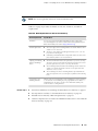
SRX210 Services Gateway
Hardware Guide
Juniper Networks, Inc.
1194 North Mathilda Avenue
Sunnyvale, California 94089
USA
408-745-2000
www.juniper.net
Revision 02
Published: 2010-05-26
This product includes the Envoy SNMP Engine, developed by Epilogue Technology, an Integrated Systems Company. Copyright © 1986-1997, Epilogue
Technology Corporation. All rights reserved. This program and its documentation were developed at private expense, and no part of them is in the public
domain.
This product includes memory allocation software developed by Mark Moraes, copyright © 1988, 1989, 1993, University of Toronto.
This product includes FreeBSD software developed by the University of California, Berkeley, and its contributors. All of the documentation and software
included in the 4.4BSD and 4.4BSD-Lite Releases is copyrighted by the Regents of the University of California. Copyright © 1979, 1980, 1983, 1986, 1988,
1989, 1991, 1992, 1993, 1994. The Regents of the University of California. All rights reserved.
GateD software copyright © 1995, the Regents of the University. All rights reserved. Gate Daemon was originated and developed through release 3.0 by
Cornell University and its collaborators. Gated is based on Kirton’s EGP, UC Berkeley’s routing daemon (routed), and DCN’s HELLO routing protocol.
Development of Gated has been supported in part by the National Science Foundation. Portions of the GateD software copyright © 1988, Regents of the
University of California. All rights reserved. Portions of the GateD software copyright © 1991, D. L. S. Associates.
This product includes software developed by Maker Communications, Inc., copyright © 1996, 1997, Maker Communications, Inc.
Juniper Networks, Junos, Steel-Belted Radius, NetScreen, and ScreenOS are registered trademarks of Juniper Networks, Inc. in the United States and other
countries. The Juniper Networks Logo, the Junos logo, and JunosE are trademarks of Juniper Networks, Inc. All other trademarks, service marks, registered
trademarks, or registered service marks are the property of their respective owners.
Juniper Networks assumes no responsibility for any inaccuracies in this document. Juniper Networks reserves the right to change, modify, transfer, or
otherwise revise this publication without notice.
Products made or sold by Juniper Networks or components thereof might be covered by one or more of the following patents that are owned by or licensed
to Juniper Networks: U.S. Patent Nos. 5,473,599, 5,905,725, 5,909,440, 6,192,051, 6,333,650, 6,359,479, 6,406,312, 6,429,706, 6,459,579, 6,493,347,
6,538,518, 6,538,899, 6,552,918, 6,567,902, 6,578,186, and 6,590,785.
SRX210 Services Gateway Hardware Guide
Copyright © 2010, Juniper Networks, Inc.
All rights reserved. Printed in USA.
Revision History
May 2010 —Revision 02
The information in this document is current as of the date listed in the revision history.
SOFTWARE LICENSE
The terms and conditions for using this software are described in the software license contained in the acknowledgment to your purchase order or, to the
extent applicable, to any reseller agreement or end-user purchase agreement executed between you and Juniper Networks. By using this software, you
indicate that you understand and agree to be bound by those terms and conditions.
Generally speaking, the software license restricts the manner in which you are permitted to use the software and may contain prohibitions against certain
uses. The software license may state conditions under which the license is automatically terminated. You should consult the license for further details.
For complete product documentation, please see the Juniper Networks Web site at www.juniper.net/techpubs.
ii
■
END USER LICENSE AGREEMENT
READ THIS END USER LICENSE AGREEMENT (“AGREEMENT”) BEFORE DOWNLOADING, INSTALLING, OR USING THE SOFTWARE. BY DOWNLOADING,
INSTALLING, OR USING THE SOFTWARE OR OTHERWISE EXPRESSING YOUR AGREEMENT TO THE TERMS CONTAINED HEREIN, YOU (AS CUSTOMER
OR IF YOU ARE NOT THE CUSTOMER, AS A REPRESENTATIVE/AGENT AUTHORIZED TO BIND THE CUSTOMER) CONSENT TO BE BOUND BY THIS
AGREEMENT. IF YOU DO NOT OR CANNOT AGREE TO THE TERMS CONTAINED HEREIN, THEN (A) DO NOT DOWNLOAD, INSTALL, OR USE THE SOFTWARE,
AND (B) YOU MAY CONTACT JUNIPER NETWORKS REGARDING LICENSE TERMS.
1. The Parties. The parties to this Agreement are (i) Juniper Networks, Inc. (if the Customer’s principal office is located in the Americas) or Juniper Networks
(Cayman) Limited (if the Customer’s principal office is located outside the Americas) (such applicable entity being referred to herein as “Juniper”), and (ii)
the person or organization that originally purchased from Juniper or an authorized Juniper reseller the applicable license(s) for use of the Software (“Customer”)
(collectively, the “Parties”).
2. The Software. In this Agreement, “Software” means the program modules and features of the Juniper or Juniper-supplied software, for which Customer
has paid the applicable license or support fees to Juniper or an authorized Juniper reseller, or which was embedded by Juniper in equipment which Customer
purchased from Juniper or an authorized Juniper reseller. “Software” also includes updates, upgrades and new releases of such software. “Embedded
Software” means Software which Juniper has embedded in or loaded onto the Juniper equipment and any updates, upgrades, additions or replacements
which are subsequently embedded in or loaded onto the equipment.
3. License Grant. Subject to payment of the applicable fees and the limitations and restrictions set forth herein, Juniper grants to Customer a non-exclusive
and non-transferable license, without right to sublicense, to use the Software, in executable form only, subject to the following use restrictions:
a. Customer shall use Embedded Software solely as embedded in, and for execution on, Juniper equipment originally purchased by Customer from Juniper
or an authorized Juniper reseller.
b. Customer shall use the Software on a single hardware chassis having a single processing unit, or as many chassis or processing units for which Customer
has paid the applicable license fees; provided, however, with respect to the Steel-Belted Radius or Odyssey Access Client software only, Customer shall use
such Software on a single computer containing a single physical random access memory space and containing any number of processors. Use of the
Steel-Belted Radius or IMS AAA software on multiple computers or virtual machines (e.g., Solaris zones) requires multiple licenses, regardless of whether
such computers or virtualizations are physically contained on a single chassis.
c. Product purchase documents, paper or electronic user documentation, and/or the particular licenses purchased by Customer may specify limits to
Customer’s use of the Software. Such limits may restrict use to a maximum number of seats, registered endpoints, concurrent users, sessions, calls,
connections, subscribers, clusters, nodes, realms, devices, links, ports or transactions, or require the purchase of separate licenses to use particular features,
functionalities, services, applications, operations, or capabilities, or provide throughput, performance, configuration, bandwidth, interface, processing,
temporal, or geographical limits. In addition, such limits may restrict the use of the Software to managing certain kinds of networks or require the Software
to be used only in conjunction with other specific Software. Customer’s use of the Software shall be subject to all such limitations and purchase of all applicable
licenses.
d. For any trial copy of the Software, Customer’s right to use the Software expires 30 days after download, installation or use of the Software. Customer
may operate the Software after the 30-day trial period only if Customer pays for a license to do so. Customer may not extend or create an additional trial
period by re-installing the Software after the 30-day trial period.
e. The Global Enterprise Edition of the Steel-Belted Radius software may be used by Customer only to manage access to Customer’s enterprise network.
Specifically, service provider customers are expressly prohibited from using the Global Enterprise Edition of the Steel-Belted Radius software to support any
commercial network access services.
The foregoing license is not transferable or assignable by Customer. No license is granted herein to any user who did not originally purchase the applicable
license(s) for the Software from Juniper or an authorized Juniper reseller.
4. Use Prohibitions. Notwithstanding the foregoing, the license provided herein does not permit the Customer to, and Customer agrees not to and shall
not: (a) modify, unbundle, reverse engineer, or create derivative works based on the Software; (b) make unauthorized copies of the Software (except as
necessary for backup purposes); (c) rent, sell, transfer, or grant any rights in and to any copy of the Software, in any form, to any third party; (d) remove
any proprietary notices, labels, or marks on or in any copy of the Software or any product in which the Software is embedded; (e) distribute any copy of
the Software to any third party, including as may be embedded in Juniper equipment sold in the secondhand market; (f) use any ‘locked’ or key-restricted
feature, function, service, application, operation, or capability without first purchasing the applicable license(s) and obtaining a valid key from Juniper, even
if such feature, function, service, application, operation, or capability is enabled without a key; (g) distribute any key for the Software provided by Juniper
to any third party; (h) use the Software in any manner that extends or is broader than the uses purchased by Customer from Juniper or an authorized Juniper
reseller; (i) use Embedded Software on non-Juniper equipment; (j) use Embedded Software (or make it available for use) on Juniper equipment that the
Customer did not originally purchase from Juniper or an authorized Juniper reseller; (k) disclose the results of testing or benchmarking of the Software to
any third party without the prior written consent of Juniper; or (l) use the Software in any manner other than as expressly provided herein.
5. Audit. Customer shall maintain accurate records as necessary to verify compliance with this Agreement. Upon request by Juniper, Customer shall furnish
such records to Juniper and certify its compliance with this Agreement.
■
iii
6. Confidentiality. The Parties agree that aspects of the Software and associated documentation are the confidential property of Juniper. As such, Customer
shall exercise all reasonable commercial efforts to maintain the Software and associated documentation in confidence, which at a minimum includes
restricting access to the Software to Customer employees and contractors having a need to use the Software for Customer’s internal business purposes.
7. Ownership. Juniper and Juniper’s licensors, respectively, retain ownership of all right, title, and interest (including copyright) in and to the Software,
associated documentation, and all copies of the Software. Nothing in this Agreement constitutes a transfer or conveyance of any right, title, or interest in
the Software or associated documentation, or a sale of the Software, associated documentation, or copies of the Software.
8. Warranty, Limitation of Liability, Disclaimer of Warranty. The warranty applicable to the Software shall be as set forth in the warranty statement that
accompanies the Software (the “Warranty Statement”). Nothing in this Agreement shall give rise to any obligation to support the Software. Support services
may be purchased separately. Any such support shall be governed by a separate, written support services agreement. TO THE MAXIMUM EXTENT PERMITTED
BY LAW, JUNIPER SHALL NOT BE LIABLE FOR ANY LOST PROFITS, LOSS OF DATA, OR COSTS OR PROCUREMENT OF SUBSTITUTE GOODS OR SERVICES,
OR FOR ANY SPECIAL, INDIRECT, OR CONSEQUENTIAL DAMAGES ARISING OUT OF THIS AGREEMENT, THE SOFTWARE, OR ANY JUNIPER OR
JUNIPER-SUPPLIED SOFTWARE. IN NO EVENT SHALL JUNIPER BE LIABLE FOR DAMAGES ARISING FROM UNAUTHORIZED OR IMPROPER USE OF ANY
JUNIPER OR JUNIPER-SUPPLIED SOFTWARE. EXCEPT AS EXPRESSLY PROVIDED IN THE WARRANTY STATEMENT TO THE EXTENT PERMITTED BY LAW,
JUNIPER DISCLAIMS ANY AND ALL WARRANTIES IN AND TO THE SOFTWARE (WHETHER EXPRESS, IMPLIED, STATUTORY, OR OTHERWISE), INCLUDING
ANY IMPLIED WARRANTY OF MERCHANTABILITY, FITNESS FOR A PARTICULAR PURPOSE, OR NONINFRINGEMENT. IN NO EVENT DOES JUNIPER
WARRANT THAT THE SOFTWARE, OR ANY EQUIPMENT OR NETWORK RUNNING THE SOFTWARE, WILL OPERATE WITHOUT ERROR OR INTERRUPTION,
OR WILL BE FREE OF VULNERABILITY TO INTRUSION OR ATTACK. In no event shall Juniper’s or its suppliers’ or licensors’ liability to Customer, whether
in contract, tort (including negligence), breach of warranty, or otherwise, exceed the price paid by Customer for the Software that gave rise to the claim, or
if the Software is embedded in another Juniper product, the price paid by Customer for such other product. Customer acknowledges and agrees that Juniper
has set its prices and entered into this Agreement in reliance upon the disclaimers of warranty and the limitations of liability set forth herein, that the same
reflect an allocation of risk between the Parties (including the risk that a contract remedy may fail of its essential purpose and cause consequential loss),
and that the same form an essential basis of the bargain between the Parties.
9. Termination. Any breach of this Agreement or failure by Customer to pay any applicable fees due shall result in automatic termination of the license
granted herein. Upon such termination, Customer shall destroy or return to Juniper all copies of the Software and related documentation in Customer’s
possession or control.
10. Taxes. All license fees payable under this agreement are exclusive of tax. Customer shall be responsible for paying Taxes arising from the purchase of
the license, or importation or use of the Software. If applicable, valid exemption documentation for each taxing jurisdiction shall be provided to Juniper prior
to invoicing, and Customer shall promptly notify Juniper if their exemption is revoked or modified. All payments made by Customer shall be net of any
applicable withholding tax. Customer will provide reasonable assistance to Juniper in connection with such withholding taxes by promptly: providing Juniper
with valid tax receipts and other required documentation showing Customer’s payment of any withholding taxes; completing appropriate applications that
would reduce the amount of withholding tax to be paid; and notifying and assisting Juniper in any audit or tax proceeding related to transactions hereunder.
Customer shall comply with all applicable tax laws and regulations, and Customer will promptly pay or reimburse Juniper for all costs and damages related
to any liability incurred by Juniper as a result of Customer’s non-compliance or delay with its responsibilities herein. Customer’s obligations under this
Section shall survive termination or expiration of this Agreement.
11. Export. Customer agrees to comply with all applicable export laws and restrictions and regulations of any United States and any applicable foreign
agency or authority, and not to export or re-export the Software or any direct product thereof in violation of any such restrictions, laws or regulations, or
without all necessary approvals. Customer shall be liable for any such violations. The version of the Software supplied to Customer may contain encryption
or other capabilities restricting Customer’s ability to export the Software without an export license.
12. Commercial Computer Software. The Software is “commercial computer software” and is provided with restricted rights. Use, duplication, or disclosure
by the United States government is subject to restrictions set forth in this Agreement and as provided in DFARS 227.7201 through 227.7202-4, FAR 12.212,
FAR 27.405(b)(2), FAR 52.227-19, or FAR 52.227-14(ALT III) as applicable.
13. Interface Information. To the extent required by applicable law, and at Customer's written request, Juniper shall provide Customer with the interface
information needed to achieve interoperability between the Software and another independently created program, on payment of applicable fee, if any.
Customer shall observe strict obligations of confidentiality with respect to such information and shall use such information in compliance with any applicable
terms and conditions upon which Juniper makes such information available.
14. Third Party Software. Any licensor of Juniper whose software is embedded in the Software and any supplier of Juniper whose products or technology
are embedded in (or services are accessed by) the Software shall be a third party beneficiary with respect to this Agreement, and such licensor or vendor
shall have the right to enforce this Agreement in its own name as if it were Juniper. In addition, certain third party software may be provided with the
Software and is subject to the accompanying license(s), if any, of its respective owner(s). To the extent portions of the Software are distributed under and
subject to open source licenses obligating Juniper to make the source code for such portions publicly available (such as the GNU General Public License
(“GPL”) or the GNU Library General Public License (“LGPL”)), Juniper will make such source code portions (including Juniper modifications, as appropriate)
available upon request for a period of up to three years from the date of distribution. Such request can be made in writing to Juniper Networks, Inc., 1194
N. Mathilda Ave., Sunnyvale, CA 94089, ATTN: General Counsel. You may obtain a copy of the GPL at http://www.gnu.org/licenses/gpl.html, and
a copy of the LGPL at http://www.gnu.org/licenses/lgpl.html .
15. Miscellaneous. This Agreement shall be governed by the laws of the State of California without reference to its conflicts of laws principles. The provisions
of the U.N. Convention for the International Sale of Goods shall not apply to this Agreement. For any disputes arising under this Agreement, the Parties
hereby consent to the personal and exclusive jurisdiction of, and venue in, the state and federal courts within Santa Clara County, California. This Agreement
constitutes the entire and sole agreement between Juniper and the Customer with respect to the Software, and supersedes all prior and contemporaneous
iv
■
agreements relating to the Software, whether oral or written (including any inconsistent terms contained in a purchase order), except that the terms of a
separate written agreement executed by an authorized Juniper representative and Customer shall govern to the extent such terms are inconsistent or conflict
with terms contained herein. No modification to this Agreement nor any waiver of any rights hereunder shall be effective unless expressly assented to in
writing by the party to be charged. If any portion of this Agreement is held invalid, the Parties agree that such invalidity shall not affect the validity of the
remainder of this Agreement. This Agreement and associated documentation has been written in the English language, and the Parties agree that the English
version will govern. (For Canada: Les parties aux présentés confirment leur volonté que cette convention de même que tous les documents y compris tout
avis qui s'y rattaché, soient redigés en langue anglaise. (Translation: The parties confirm that this Agreement and all related documentation is and will be
in the English language)).
■
v
vi
■
Table of Contents
About This Guide
xv
Objectives ......................................................................................................xv
Audience .......................................................................................................xv
Documentation Conventions .........................................................................xv
SRX Series Documentation and Release Notes .............................................xvii
Obtaining Documentation ..........................................................................xviii
Documentation Feedback ...........................................................................xviii
Requesting Technical Support .....................................................................xviii
Part 1
SRX210 Services Gateway Overview
Chapter 1
Introduction to the SRX210 Services Gateway
3
SRX210 Services Gateway Description ............................................................3
About the SRX210 Services Gateway ........................................................3
SRX210 Services Gateway Models ............................................................3
Accessing the SRX210 Services Gateway ..................................................4
SRX210 Services Gateway Hardware Features ................................................4
Chapter 2
SRX210 Services Gateway Hardware Components and
Specifications
7
SRX210 Services Gateway Specifications .........................................................7
SRX210 Services Gateway Front Panel and Back Panel Views (Low Memory,
High Memory and PoE Version) ..............................................................10
SRX210 Services Gateway Front Panel ...................................................10
SRX210 Services Gateway Back Panel ....................................................11
SRX210 Services Gateway with Integrated Convergence Services Front Panel
and Back Panel Views .............................................................................12
SRX210 Services Gateway with Integrated Convergence Services Front
Panel ................................................................................................12
SRX210 Services Gateway with Integrated Convergence Services Back
Panel ................................................................................................13
SRX210 Services Gateway Built-In Interfaces ................................................14
SRX210 Services Gateway LEDs ....................................................................18
Front Panel LEDs ....................................................................................18
Ethernet Port LEDs .................................................................................20
Voice Interface Port LED .........................................................................21
Table of Contents
■
vii
SRX210 Services Gateway Hardware Guide
SRX210 Services Gateway Boot Devices and Dual-Root Partitioning
Scheme ...................................................................................................23
Boot Devices ...........................................................................................23
Dual-Root Partitioning Scheme ...............................................................23
SRX210 Services Gateway Cooling System ....................................................24
SRX210 Services Gateway Power Supply .......................................................26
Chapter 3
SRX210 Services Gateway 3G ExpressCard
29
SRX210 Services Gateway 3G ExpressCard Overview ...................................29
Introduction ............................................................................................29
Supported Modem Types ........................................................................29
Using the 3G ExpressCard .......................................................................30
Key Features ...........................................................................................30
Physical Specifications ............................................................................31
Installing the 3G ExpressCard in the SRX210 Services Gateway ExpressCard
Slot .........................................................................................................32
SRX210 Services Gateway 3G ExpressCard Basic CLI Commands .................33
Chapter 4
SRX210 Services Gateway Power over Ethernet Support
35
SRX210 Services Gateway PoE Overview ......................................................35
Introduction ............................................................................................35
PoE Classes and Power Ratings ..............................................................36
Configuring PoE Functionality on the SRX210 Services Gateway ...................37
Chapter 5
SRX210 Services Gateway with Integrated Convergence
Services
39
About the SRX210 Services Gateway with Integrated Convergence
Services ..................................................................................................39
Basic Functions .......................................................................................40
Supported Features .................................................................................40
Common Deployment Scenarios ............................................................41
Understanding the Functions of the SRX210 Services Gateway with Integrated
Convergence Services .............................................................................41
SRX210 Services Gateway Integrated Convergence Services
Interoperability .......................................................................................42
Configuring the SRX210 Services Gateway with Integrated Convergence
Services ..................................................................................................43
Chapter 6
SRX210 Services Gateway Mini-Physical Interface Modules
45
SRX210 Services Gateway Mini-Physical Interface Modules ...........................45
viii
■
Table of Contents
Table of Contents
Part 2
Setting Up the SRX210 Services Gateway
Chapter 7
Preparing the Site for the SRX210 Services Gateway Installation
49
Site Preparation Checklist for the SRX210 Services Gateway .........................49
General Site Guidelines for Installing the SRX210 Services Gateway ..............51
SRX210 Services Gateway Cabinet Requirements .........................................51
SRX210 Services Gateway Rack Requirements ..............................................52
Clearance Requirements for Airflow and Hardware Maintenance of the
SRX210 Services Gateway ......................................................................54
SRX210 Services Gateway Electrical and Power Requirements .....................55
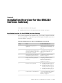
Chapter 8
Installation Overview for the SRX210 Services Gateway
57
Installation Overview for the SRX210 Services Gateway ................................57
Chapter 9
Required Tools and Parts for Installing and Maintaining the SRX210
Services Gateway
59
Required Tools and Parts for Installing and Maintaining the SRX210 Services
Gateway ..................................................................................................59
Chapter 10
Unpacking the SRX210 Services Gateway
61
Unpacking the SRX210 Services Gateway .....................................................61
Verifying Parts Received with the SRX210 Services Gateway ........................61
Chapter 11
Preparing the SRX210 Services Gateway for Installation
65
Preparing the SRX210 Services Gateway for Rack-Mount, Desk-Mount, and
Wall-Mount Installation ...........................................................................65
Preparing the SRX210 Services Gateway for Rack-Mount Installation ............66
Preparing the SRX210 Services Gateway for Desk-Mount Installation ............67
Preparing the SRX210 Services Gateway for Wall-Mount Installation ............68
Chapter 12
Installing the SRX210 Services Gateway
69
SRX210 Services Gateway Safety Requirements, Warnings, and
Guidelines ...............................................................................................69
SRX210 Services Gateway Installation ...........................................................69
Adjusting the Power Supply Adapter Tray for the SRX210 Services
Gateway for Rack-Mount Installation ................................................70
Installing the SRX210 Services Gateway in a Rack ..................................71
Installing the SRX210 Services Gateway on a Desk .................................75
Table of Contents
■
ix
SRX210 Services Gateway Hardware Guide
Installing the SRX210 Services Gateway on a Wall ..................................76
Replacing or Installing Mini-Physical Interface Modules in the SRX210 Services
Gateway ..................................................................................................78
Chapter 13
Connecting, Grounding, and Powering On the SRX210 Services
Gateway
81
Connecting the SRX210 Services Gateway to the Power Supply ....................81
Connecting and Organizing Interface Cables to the SRX210 Services
Gateway ..................................................................................................83
Grounding the SRX210 Services Gateway ......................................................84
Powering On and Powering Off the SRX210 Services Gateway .....................85
Powering On the SRX210 Services Gateway ...........................................85
Powering Off the SRX210 Services Gateway ...........................................86
Resetting the SRX210 Services Gateway .................................................87
Chapter 14
SRX210 Services Gateway Autoinstallation
89
SRX210 Services Gateway Autoinstallation Overview ....................................89
Chapter 15
Connecting the SRX210 Services Gateway to Management
Devices
91
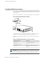
Connecting an SRX210 Services Gateway to the J-Web Interface ..................91
Connecting an SRX210 Services Gateway to the CLI Locally ..........................95
Connecting an SRX210 Services Gateway to the CLI Remotely ......................96
Connecting the Modem at the SRX210 Services Gateway End .......................97
Connecting the Modem to the Console Port on the SRX210 Services
Gateway ..................................................................................................98
Connecting to the CLI at the User End for the SRX210 Services Gateway ......99
Chapter 16
Performing Initial Software Configuration on the SRX210 Services
Gateway
101
SRX210 Services Gateway Software Configuration Overview ......................101
Preparing SRX210 Services Gateway for Configuration .........................101
Understanding Built-In Ethernet Ports ...................................................102
Mapping the Chassis Cluster Ports ........................................................102
Understanding Management Access .....................................................103
Performing Initial Software Configuration on the SRX210 Services Gateway
Using the CLI ........................................................................................104
Performing Initial Software Configuration on the SRX210 Services Gateway
Using the J-Web Interface .....................................................................107
Establishing Basic Connectivity .............................................................107
Configuring Basic System Properties .....................................................108
SRX210 Services Gateway Secure Web Access Overview ............................111
x
■
Table of Contents
Table of Contents
Part 3
Maintaining and Monitoring the SRX210 Services Gateway
Hardware
Chapter 17
Maintaining the SRX210 Services Gateway Hardware
Components
115
Maintaining the SRX210 Services Gateway Hardware Components ............115
Chapter 18
Monitoring the SRX210 Services Gateway
117
Monitoring Hardware Components on the SRX210 Services Gateway .........117
Monitoring the SRX210 Services Gateway Chassis Using the CLI ..........117
Monitoring the SRX210 Services Gateway Components Using LEDs .....120
Monitoring the SRX210 Services Gateway Using Chassis Alarm
Conditions ......................................................................................122
Monitoring the SRX210 Services Gateway Power System .....................125
Resetting the Configuration File When the SRX210 Services Gateway Is
Inaccessible ..........................................................................................126
Using the Reset Config Button on the SRX210 Services Gateway ..........126
Changing the Reset Config Button Behavior on the SRX210 Services
Gateway .........................................................................................127
Juniper Networks Technical Assistance Center ............................................128
Part 4
Appendixes
Appendix A
Safety and Regulatory Compliance Information
131
SRX210 Services Gateway Definition of Safety Warning Levels ...................131
SRX210 Services Gateway General Safety Guidelines and Warnings ............133
SRX210 Services Gateway Fire Safety Requirements ...................................137
SRX210 Services Gateway Installation Safety Guidelines and Warnings ......138
SRX210 Services Gateway Laser and LED Safety Guidelines and
Warnings ..............................................................................................142
Laser and LED Safety Guidelines and Warnings ....................................142
General Laser Safety Guidelines ......................................................142
Class 1 Laser Product Warning .......................................................142
Class 1 LED Product Warning .........................................................143
Laser Beam Warning ......................................................................143
Radiation from Open Port Apertures Warning ................................144
SRX210 Services Gateway Maintenance and Operational Safety Guidelines
and Warnings .......................................................................................145
Safety Guidelines and Warnings ............................................................145
Battery Handling Warning ..............................................................145
Jewelry Removal Warning ..............................................................146
Lightning Activity Warning .............................................................147
Operating Temperature Warning ....................................................148
Product Disposal Warning ..............................................................149
Table of Contents
■
xi
SRX210 Services Gateway Hardware Guide
SRX210 Services Gateway Electrical Safety Guidelines and Warnings .........150
SRX210 Services Gateway Agency Approvals ..............................................151
SRX210 Services Gateway Compliance Statements for EMC
Requirements .......................................................................................152
SRX210 Services Gateway Compliance Statements for Environmental
Requirements .......................................................................................154
SRX210 Services Gateway Compliance Statements for Acoustic Noise ........154
Appendix B
SRX210 Services Gateway Power Guidelines, Requirements, and
Specifications
157
SRX210 Services Gateway Site Electrical Wiring Guidelines .........................157
SRX210 Services Gateway Power Specifications and Requirements ............158
SRX210 Services Gateway Grounding Specifications ...................................159
Appendix C
SRX210 Services Gateway Interface Cable Specifications and
Connector Pinouts
161
Interface Cable and Wire Specifications for the SRX210 Services
Gateway ................................................................................................161
RJ-45 Connector Pinouts for the SRX210 Services Gateway Ethernet Port ....162
RJ-45 Connector Pinouts for the SRX210 Services Gateway Console Port ....163
RJ-11 Connector Pinouts for the SRX210 Services Gateway with Integrated
Convergence Services FXO and FXS Ports ............................................164
Appendix D
Contacting Customer Support and Returning the SRX210 Services
Gateway Hardware
167
Return Procedure for the SRX210 Services Gateway ...................................167
Locating an SRX210 Services Gateway Component Serial Number and Agency
Labels ...................................................................................................168
Listing the SRX210 Services Gateway and Component Details with the
CLI ..................................................................................................168
SRX210 Services Gateway Chassis Serial Number and Agency
Labels .............................................................................................169
SRX210 Services Gateway Mini-Physical Interface Module Serial Number
Label ..............................................................................................169
Contacting Customer Support to Obtain Return Materials Authorization .....170
Information You Might Need to Supply to Juniper Networks Technical
Assistance Center ...........................................................................170
Contacting Customer Support ...............................................................170
Packing the SRX210 Services Gateway and Components for Shipment .......171
Packing the Services Gateway ...............................................................171
Packing the Components for Shipment .................................................172
xii
■
Table of Contents
Table of Contents
Part 5
Index
Index ...........................................................................................................175
Table of Contents
■
xiii
SRX210 Services Gateway Hardware Guide
xiv
■
Table of Contents
About This Guide
This preface includes the following topics:
■
Objectives on page xv
■
Audience on page xv
■
Documentation Conventions on page xv
■
SRX Series Documentation and Release Notes on page xvii
■
Obtaining Documentation on page xviii
■
Documentation Feedback on page xviii
■
Requesting Technical Support on page xviii
Objectives
This guide describes hardware components and installation, basic configuration, and
basic troubleshooting procedures for the Juniper Networks SRX210 Services Gateway.
It explains how to prepare your site for services gateway installation, unpack and
install the hardware, power on the services gateway, perform initial software
configuration, and perform routine maintenance. After completing the installation
and basic configuration procedures covered in this guide, see the JUNOS software
configuration guides for information about further JUNOS software configuration.
Audience
This guide is designed for network administrators who are installing and maintaining
a Juniper Networks SRX210 Services Gateway or preparing a site for device
installation. To use this guide, you need a broad understanding of networks in general
and the Internet in particular, networking principles, and network configuration. Any
detailed discussion of these concepts is beyond the scope of this guide.
Documentation Conventions
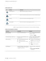
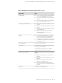
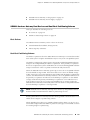
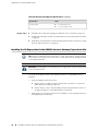
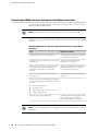
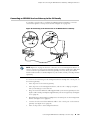
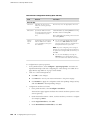
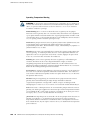
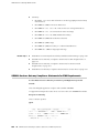
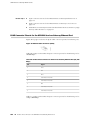
Table 1 on page xvi defines the notice icons used in this guide.
Objectives
■
xv
SRX210 Services Gateway Hardware Guide
Table 1: Notice Icons
Icon
Meaning
Description
Informational note
Indicates important features or instructions.
Caution
Indicates a situation that might result in loss of data or hardware damage.
Warning
Alerts you to the risk of personal injury or death.
Laser warning
Alerts you to the risk of personal injury from a laser.
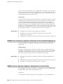
Table 2 on page xvi defines the text and syntax conventions used in this guide.
Table 2: Text and Syntax Conventions
Convention
Description
Examples
Bold text like this
Represents text that you type.
To enter configuration mode, type the
configure command:
user@host> configure
Fixed-width text like this
Represents output that appears on the
terminal screen.
Italic text like this
■
Introduces important new terms.
■
Identifies book names.
■
Identifies RFC and Internet draft
titles.
Italic text like this
xvi
■
Documentation Conventions
Represents variables (options for which
you substitute a value) in commands or
configuration statements.
user@host> show chassis alarms
No alarms currently active
■
A policy term is a named structure
that defines match conditions and
actions.
■
Junos System Basics Configuration
Guide
■
RFC 1997, BGP Communities
Attribute
Configure the machine’s domain name:
[edit]
root@# set system domain-name
domain-name
About This Guide
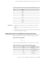
Table 2: Text and Syntax Conventions (continued)
Convention
Description
Examples
Plain text like this
Represents names of configuration
statements, commands, files, and
directories; IP addresses; configuration
hierarchy levels; or labels on routing
platform components.
■
< > (angle brackets)
Enclose optional keywords or variables.
stub <default-metric metric>;
| (pipe symbol)
Indicates a choice between the mutually
exclusive keywords or variables on either
side of the symbol. The set of choices is
often enclosed in parentheses for clarity.
broadcast | multicast
# (pound sign)
Indicates a comment specified on the
same line as the configuration statement
to which it applies.
rsvp { # Required for dynamic MPLS only
[ ] (square brackets)
Enclose a variable for which you can
substitute one or more values.
community name members [
community-ids ]
Indention and braces ( { } )
Identify a level in the configuration
hierarchy.
; (semicolon)
Identifies a leaf statement at a
configuration hierarchy level.
To configure a stub area, include
the stub statement at the [edit
protocols ospf area area-id]
hierarchy level.
■
The console port is labeled
CONSOLE.
(string1 | string2 | string3)
[edit]
routing-options {
static {
route default {
nexthop address;
retain;
}
}
}
J-Web GUI Conventions
Bold text like this
Represents J-Web graphical user
interface (GUI) items you click or select.
> (bold right angle bracket)
Separates levels in a hierarchy of J-Web
selections.
■
In the Logical Interfaces box, select
All Interfaces.
■
To cancel the configuration, click
Cancel.
In the configuration editor hierarchy,
select Protocols>Ospf.
SRX Series Documentation and Release Notes
For a list of related SRX Series documentation, see
http://www.juniper.net/techpubs/hardware/srx-series-main.html.
If the information in the latest SRX Series Release Notes differs from the information
in the documentation, follow the SRX Series Release Notes.
SRX Series Documentation and Release Notes
■
xvii
SRX210 Services Gateway Hardware Guide
Obtaining Documentation
To obtain the most current version of all Juniper Networks technical documentation,
see the products documentation page on the Juniper Networks web site at
http://www.juniper.net/techpubs.
To order printed copies of this guide and other Juniper Networks technical documents,
or to order a documentation CD, which contains this guide, contact your sales
representative.
Copies of the Management Information Bases (MIBs) available in a software release
are included on the documentation CDs and at http://www.juniper.net/.
Documentation Feedback
We encourage you to provide feedback, comments, and suggestions so that we can
improve the documentation. You can send your comments to
[email protected], or fill out the documentation feedback form at
http://www.juniper.net/techpubs/docbug/docbugreport.html. If you are using e-mail, be sure
to include the following information with your comments:
■
Document name
■
Document part number
■
Page number
■
Software release version (not required for Network Operations Guides [NOGs])
Requesting Technical Support
Technical product support is available through the Juniper Networks Technical
Assistance Center (JTAC). If you are a customer with an active J-Care or JNASC support
contract, or are covered under warranty, and need postsales technical support, you
can access our tools and resources online or open a case with JTAC.
■
JTAC policies- For a complete understanding of our JTAC procedures and policies,
review the JTAC User Guide located at
http://www.juniper.net/customers/support/downloads/710059.pdf.
■
Product warranties- For product warranty information, visit
http://www.juniper.net/support/warranty/.
■
JTAC Hours of Operation- The JTAC centers have resources available 24 hours a
day, 7 days a week, 365 days a year.
Self-Help Online Tools and Resources
For quick and easy problem resolution, Juniper Networks has designed an online
self-service portal called the Customer Support Center (CSC) that provides you with
the following features:
xviii
■
Obtaining Documentation
About This Guide
■
Find CSC offerings: http://www.juniper.net/customers/support/
■
Search for known bugs: http://www2.juniper.net/kb/
■
Find product documentation: http://www.juniper.net/techpubs/
■
Find solutions and answer questions using our Knowledge Base:
http://kb.juniper.net/
■
Download the latest versions of software and review release notes:
http://www.juniper.net/customers/csc/software/
■
Search technical bulletins for relevant hardware and software notifications:
https://www.juniper.net/alerts/
■
Join and participate in the Juniper Networks Community Forum:
http://www.juniper.net/company/communities/
■
Open a case online in the CSC Case Manager: http://www.juniper.net/cm/
To verify service entitlement by product serial number, use our Serial Number
Entitlement (SNE) tool located at https://tools.juniper.net/SerialNumberEntitlementSearch/.
Opening a Case with JTAC
You can open a case with JTAC on the Web or by telephone.
■
Use the Case Manager tool in the CSC at http://www.juniper.net/cm/.
■
Call 1-888-314-JTAC (1-888-314-5822 toll-free in the USA, Canada, and Mexico).
For international or direct-dial options in countries without toll-free numbers, visit
us at http://www.juniper.net/support/requesting-support.html.
Requesting Technical Support
■
xix
SRX210 Services Gateway Hardware Guide
xx
■
Requesting Technical Support
Part 1
SRX210 Services Gateway Overview
■
Introduction to the SRX210 Services Gateway on page 3
■
SRX210 Services Gateway Hardware Components and Specifications on page 7
■
SRX210 Services Gateway 3G ExpressCard on page 29
■
SRX210 Services Gateway Power over Ethernet Support on page 35
■
SRX210 Services Gateway with Integrated Convergence Services on page 39
■
SRX210 Services Gateway Mini-Physical Interface Modules on page 45
SRX210 Services Gateway Overview
■
1
SRX210 Services Gateway Hardware Guide
2
■
SRX210 Services Gateway Overview
Chapter 1
Introduction to the SRX210 Services
Gateway
This chapter includes the following topics:
■
SRX210 Services Gateway Description on page 3
■
SRX210 Services Gateway Hardware Features on page 4
SRX210 Services Gateway Description
This topic includes the following sections:
■
About the SRX210 Services Gateway on page 3
■
SRX210 Services Gateway Models on page 3
■
Accessing the SRX210 Services Gateway on page 4
About the SRX210 Services Gateway
The Juniper Networks SRX210 Services Gateway offers complete functionality and
flexibility for delivering secure, reliable data and voice services over IP, along with
multiple interfaces that support WAN and LAN connectivity. Features include
SIP/analog voice support, flexible data/voice T1/E1, and Power over Ethernet (PoE).
The SRX210 Services Gateway provides Internet Protocol Security (IPsec), virtual
private network (VPN), and firewall services for small-sized and medium-sized
companies and enterprise branch and remote offices. Additional security features
also include Unified Threat Management (UTM), which consists of IPS antispam,
antivirus, and Web filtering.
The SRX210 Services Gateway runs the JUNOS operating system.
SRX210 Services Gateway Models
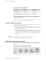
The SRX210 Services Gateway is available in four models, which are listed in Table
3 on page 4.
SRX210 Services Gateway Description
■
3
SRX210 Services Gateway Hardware Guide
Table 3: SRX210 Services Gateway Models
Product Name
Device Type
Model Number
SRX210 Services Gateway
Low Memory
SRX210B
SRX210 Services Gateway
High Memory
SRX210H
SRX210 Services Gateway with
PoE
Power over Ethernet (PoE)
SRX210H-POE
SRX210 Services Gateway with
integrated convergence services
Voice
SRX210H-P-MGW
All SRX210 Services Gateways run the JUNOS operating system.
Accessing the SRX210 Services Gateway
Two user interfaces are available for monitoring, configuring, troubleshooting, and
managing the SRX210 Services Gateway:
Related Topics
■
J-Web interface: Web-based graphical interface that allows you to operate a
services gateway without commands. The J-Web interface provides access to all
JUNOS functionality and features.
■
JUNOS command-line interface (CLI): Juniper Networks command shell that runs
on top of a UNIX-based operating system kernel. The CLI is a straightforward
command interface. On a single line, you type commands that are executed
when you press the Enter key. The CLI provides command Help and command
completion.
■
SRX210 Services Gateway Specifications on page 7
■
SRX210 Services Gateway Hardware Features on page 4
SRX210 Services Gateway Hardware Features
Table 4 on page 4 lists the hardware features supported on the SRX210 Services
Gateway.
Table 4: SRX210 Services Gateway Hardware Features
4
■
Feature
SRX210
Services
Gateway Low
Memory
SRX210
Services
Gateway High
Memory
SRX210
Services
Gateway Power
over Ethernet
SRX210
Services
Gateway with
Integrated
Convergence
Services
DDR memory
512 MB
1 GB
1 GB
1 GB
SRX210 Services Gateway Hardware Features
Chapter 1: Introduction to the SRX210 Services Gateway
Table 4: SRX210 Services Gateway Hardware Features (continued)
SRX210
Services
Gateway Low
Memory
SRX210
Services
Gateway High
Memory
SRX210
Services
Gateway Power
over Ethernet
SRX210
Services
Gateway with
Integrated
Convergence
Services
SIP/analog voice
support
No
No
No
Yes
PoE support
No
No
Yes
Yes
Power supply
adapter
60 watts
60 watts
150 watts
150 watts
AC input voltage
100 to 240 VAC
100 to 240 VAC
100 to 240 VAC
100 to 240 VAC
Gigabit Ethernet
ports
2
2
2
2
Fast Ethernet
ports
6
6
6
6
Console port
1
1
1
1
USB ports
2
2
2
2
Foreign
Exchange
Subscriber (FXS)
and Foreign
Exchange Office
(FXO) interface
None
None
None
Two FXS ports
and two FXO
ports
Mini-PIM slots
1
1
1
1
LEDs
Status, Alarm,
HA, Power,
Mini-PIMs, 3G
ExpressCard,
Port (TX/RX and
PoE)
Status, Alarm,
HA, Power,
Mini-PIMs, 3G
ExpressCard,
Port (TX/RX and
PoE)
Status, Alarm,
HA, Power,
Mini-PIMs, 3G
ExpressCard,
Port (TX/RX and
PoE)
Status, Alarm,
HA, Power,
Mini-PIMs, 3G
ExpressCard,
Port (TX/RX and
PoE), and Voice
Interface
NAND flash
1 GB
1 GB
1 GB
2 GB
Fans
1
1
1
2
Feature
NOTE: The PoE LED is enabled only on the PoE model of the SRX210 Services
Gateway. For non-PoE services gateways, the PoE LED remains off.
For more details on the SRX210 Services Gateway software features and licenses,
see the JUNOS Software Administration Guide.
SRX210 Services Gateway Hardware Features
■
5
SRX210 Services Gateway Hardware Guide
Related Topics
6
■
■
SRX210 Services Gateway Description on page 3
■
SRX210 Services Gateway Specifications on page 7
SRX210 Services Gateway Hardware Features
Chapter 2
SRX210 Services Gateway Hardware
Components and Specifications
This chapter includes the following topics:
■
SRX210 Services Gateway Specifications on page 7
■
SRX210 Services Gateway Front Panel and Back Panel Views (Low Memory, High
Memory and PoE Version) on page 10
■
SRX210 Services Gateway with Integrated Convergence Services Front Panel
and Back Panel Views on page 12
■
SRX210 Services Gateway Built-In Interfaces on page 14
■
SRX210 Services Gateway LEDs on page 18
■
SRX210 Services Gateway Boot Devices and Dual-Root Partitioning
Scheme on page 23
■
SRX210 Services Gateway Cooling System on page 24
■
SRX210 Services Gateway Power Supply on page 26
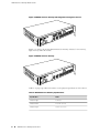
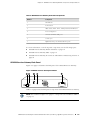
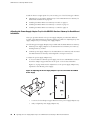
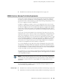
SRX210 Services Gateway Specifications
The SRX210 Services Gateway chassis is a rigid sheet metal structure of 1 rack Unit
(U) height that houses all the other hardware components.
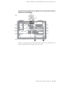
Figure 1 on page 8 shows the SRX210 Services Gateway with Integrated Convergence
Services chassis.
SRX210 Services Gateway Specifications
■
7
SRX210 Services Gateway Hardware Guide
Figure 1: SRX210 Services Gateway with Integrated Convergence Services
Figure 2 on page 8 shows the SRX210 Services Gateway chassis (for low memory,
high memory, and PoE models).
Figure 2: SRX210 Services Gateway
Table 5 on page 8 provides information on the physical specifications of the device.
Table 5: SRX210 Services Gateway Specifications
8
■
Specification
Value
Chassis height
1 unit (U)
Chassis width
11.02 in. (28 cm)
Chassis depth
7.04 in. (17.9 cm)
SRX210 Services Gateway Specifications
Chapter 2: SRX210 Services Gateway Hardware Components and Specifications
Table 5: SRX210 Services Gateway Specifications (continued)
Specification
Value
Chassis weight
■
3.43 lb (1.56 kg) for SRX210 Services Gateway
Low Memory and High Memory models
■
3.50 lb (1.59 kg) for SRX210 Services Gateway
with PoE
■
3.76 lb. (1.70 kg) for SRX210 Services Gateway
with Integrated Convergence Services
■
SRX210 Services Gateway Low Memory model:
27 watts
■
SRX210 Services Gateway High Memory model:
28 watts
■
SRX210 Services Gateway PoE model: 34 watts
(excluding PoE load)
■
SRX210 Services Gateway with Integrated
Convergence Services model: 43 watts
(excluding PoE load)
■
No performance degradation up to 10,000 ft
(3048 m) for SRX210 Services Gateway Low
Memory, High Memory, and PoE models
■
No performance degradation up to 6561 ft (2000
m) for SRX210 Services Gateway with Integrated
Convergence Services)
Average power consumption
Altitude
Relative humidity
5% to 90%, noncondensing
Temperature
Normal operation ensured in temperature range of
32°F (0°C) to 104°F (+40°C)
Nonoperating storage temperature in shipping
container: –40°F (–40°C) to 158°F (70°C)
Maximum thermal output
Noise level
NOTE: These specifications are estimates and subject
to change.
■
SRX210 Services Gateway Low Memory: 120
BTU/hour
■
SRX210 Services Gateway High Memory: 126
BTU/hour
■
SRX210 Services Gateway with PoE: 164
BTU/hour (Excluding PoE load)
■
SRX210 Services Gateway with Integrated
Convergence Services: 232 BTU/hour (Excluding
PoE load)
70 dB(A) or less per EN ISO 7779
SRX210 Services Gateway Specifications
■
9
SRX210 Services Gateway Hardware Guide
CAUTION: Before removing or installing components of a functioning services
gateway, attach an electrostatic discharge (ESD) strap to an ESD point and place the
other end of the strap around your bare wrist. Failure to use an ESD strap could result
in damage to the services gateway.
Related Topics
■
SRX210 Services Gateway Description on page 3
■
SRX210 Services Gateway Front Panel and Back Panel Views (Low Memory, High
Memory and PoE Version) on page 10
■
Monitoring the SRX210 Services Gateway Components Using LEDs on page 120
■
SRX210 Services Gateway Electrical Safety Guidelines and Warnings on page 150
SRX210 Services Gateway Front Panel and Back Panel Views (Low Memory, High
Memory and PoE Version)
This topic contains views of the front panel and back panel of the SRX210 Services
Gateway high memory, low memory, and Power over Ethernet (PoE) versions. This
topic includes the following sections:
■
SRX210 Services Gateway Front Panel on page 10
■
SRX210 Services Gateway Back Panel on page 11
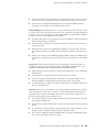
SRX210 Services Gateway Front Panel
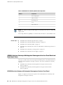
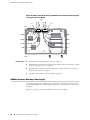
Figure 3 on page 10 shows the front panel of the SRX210 Services Gateway.
Figure 3: SRX210 Services Gateway Front Panel
Table 6 on page 11 lists the front panel components of the services gateway.
NOTE: The numbers in Figure 3 on page 10 correspond to the numbers in Table 6
on page 11.
10
■
SRX210 Services Gateway Front Panel and Back Panel Views (Low Memory, High Memory and PoE Version)
Chapter 2: SRX210 Services Gateway Hardware Components and Specifications
Table 6: SRX210 Services Gateway Front Panel Components
Number
Component
1
Mini-PIM slot
2
Power button
3
LEDs: Status, Alarm, Power, 3G ExpressCard, Mini-PIM, HA
4
Reset Config button
5
Universal Serial Bus (USB) ports
6
Console port
7
Gigabit Ethernet ports and Fast Ethernet ports
For more information on the front panel components, see the following topics:
■
SRX210 Services Gateway Built-In Interfaces on page 14
■
SRX210 Services Gateway LEDs on page 18
■
SRX210 Services Gateway Boot Devices and Dual-Root Partitioning Scheme on
page 23
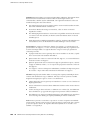
SRX210 Services Gateway Back Panel
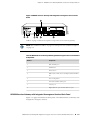
Figure 4 on page 11 illustrates the back panel of the SRX210 Services Gateway.
g031113
Figure 4: SRX210 Services Gateway Back Panel
Table 7 on page 12 lists the back panel components of the SRX210 Services Gateway.
NOTE: The numbers in Figure 4 on page 11 correspond to the numbers in Table 7
on page 12.
SRX210 Services Gateway Front Panel and Back Panel Views (Low Memory, High Memory and PoE Version)
■
11
SRX210 Services Gateway Hardware Guide
Table 7: SRX210 Services Gateway Back Panel Components
Number
Component
1
Power supply point
2
Cable tie holder
3
Grounding point
4
Lock
5
ExpressCard slot
NOTE: The cable tie holder provides support to hold the power cord on to the power
supply point.
The lock provides the capability to lock and secure the device to the installation site.
Related Topics
■
SRX210 Services Gateway Specifications on page 7
■
SRX210 Services Gateway Built-In Interfaces on page 14
■
SRX210 Services Gateway LEDs on page 18
■
SRX210 Services Gateway Boot Devices and Dual-Root Partitioning Scheme on
page 23
■
SRX210 Services Gateway Cooling System on page 24
■
SRX210 Services Gateway Power Supply on page 26
SRX210 Services Gateway with Integrated Convergence Services Front Panel and
Back Panel Views
This topic contains views of the front panel and back panel of the SRX210 Services
Gateway with Integrated Convergence Services. This topic includes the following
sections:
■
SRX210 Services Gateway with Integrated Convergence Services Front
Panel on page 12
■
SRX210 Services Gateway with Integrated Convergence Services Back
Panel on page 13
SRX210 Services Gateway with Integrated Convergence Services Front Panel
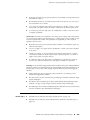
Figure 5 on page 13 shows the front panel of the SRX210 Services Gateway with
Integrated Convergence Services.
12
■
SRX210 Services Gateway with Integrated Convergence Services Front Panel and Back Panel Views
Chapter 2: SRX210 Services Gateway Hardware Components and Specifications
Figure 5: SRX210 Services Gateway with Integrated Convergence Services Front
Panel
Table 8 on page 13 lists the front panel components of the services gateway.
NOTE: The numbers in Table 8 on page 13 correspond to the numbers in Figure 5
on page 13.
Table 8: SRX210 Services Gateway with Integrated Convergence Services Front Panel
Components
Number
Component
1
FXO and FXS ports
2
Mini-PIM slot
3
Power button
4
LEDs- Status, Alarm, Power, 3G ExpressCard, Mini-PIM,
HA
5
Reset Config button
6
Universal Serial Bus (USB) ports
7
Console port
8
Gigabit Ethernet ports and Fast Ethernet ports
SRX210 Services Gateway with Integrated Convergence Services Back Panel
Figure 6 on page 14 illustrates the back panel of the SRX210 Services Gateway with
Integrated Convergence Services.
SRX210 Services Gateway with Integrated Convergence Services Front Panel and Back Panel Views
■
13
SRX210 Services Gateway Hardware Guide
g031102
Figure 6: SRX210 Services Gateway with Integrated Convergence Services Back
Panel
Table 9 on page 14 lists the back panel components of the SRX210 Services Gateway
with Integrated Convergence Services.
NOTE: The numbers in Figure 6 on page 14 correspond to the numbers in Table 9
on page 14.
Table 9: SRX210 Services Gateway with Integrated Convergence Services Back Panel
Components
Related Topics
Number
Component
1
Power supply point
2
Cable tie holder
3
Grounding point
4
Lock
5
ExpressCard slot
■
SRX210 Services Gateway Specifications on page 7
■
SRX210 Services Gateway Built-In Interfaces on page 14
■
SRX210 Services Gateway LEDs on page 18
■
SRX210 Services Gateway Boot Devices and Dual-Root Partitioning Scheme on
page 23
■
SRX210 Services Gateway Cooling System on page 24
■
SRX210 Services Gateway Power Supply on page 26
SRX210 Services Gateway Built-In Interfaces
Table 10 on page 15 summarizes the interface ports supported on the SRX210
Services Gateway.
14
■
SRX210 Services Gateway Built-In Interfaces
Chapter 2: SRX210 Services Gateway Hardware Components and Specifications
Table 10: SRX210 Services Gateway Built-In Hardware Interfaces
Interface Type
Specifications
Gigabit Ethernet
■
Consist of two fixed ports
■
Are labeled as port
ge–0/0/0 and port
ge–0/0/1 on the front
panel
■
Use an RJ-45 connector
■
Provide link speeds of
10/100/1000 Mbps
■
Operate in full-duplex
and half-duplex modes
■
Support flow control
■
Support autonegotiation
and autosensing
Description
The Gigabit Ethernet ports can
be used as follows:
■
To function as front-end
network ports
■
To provide LAN and
WAN connectivity to
hubs, switches, local
servers, and workstations
■
To forward incoming
data packets to the
device
■
To receive outgoing data
packets from the device
■
To connect power
devices to receive
network connectivity and
electric power (PoE
functionality) (For the
PoE and media gateway
model of the SRX210
Services Gateway)
Both Gigabit Ethernet ports
support Power over Ethernet
on the PoE and media gateway
models of the SRX210 Services
Gateway.
Fast Ethernet
■
Consist of six fixed ports
■
Are labeled as port
fe–0/0/2 to port
fe–0/0/7 on the front
panel
■
Provide link speeds of
10/100 Mbps
■
Operate in full-duplex
and half-duplex modes
The first two Fast Ethernet
ports support Power over
Ethernet on the SRX210
Services Gateway (PoE version
and media gateway version).
The Fast Ethernet ports can
be used as follows:
■
To provide LAN
connectivity to hubs,
switches, local servers,
and workstations
■
To forward incoming
data packets to the
device
■
To receive outgoing data
packets from the device
■
To connect power
devices to receive
network connectivity and
electric power (PoE
functionality) (For the
PoE and media gateway
model of the SRX210
Services Gateway)
SRX210 Services Gateway Built-In Interfaces
■
15
SRX210 Services Gateway Hardware Guide
Table 10: SRX210 Services Gateway Built-In Hardware Interfaces (continued)
Interface Type
Specifications
Universal Serial Bus (USB)
■
Consist of two ports
■
Function in full speed and
high speed
■
Are compliant with USB
revision 2.0
Description
The USB ports can be used as
follows:
■
To support a USB storage
device that functions as
a secondary boot device
in case of the internal
flash failure on startup, if
the USB storage device is
installed and configured
NOTE: You must install and
configure the USB storage
device on the USB port to use
it as secondary boot device.
Also, the USB device must
have JUNOS installed.
■
To provide the USB
interfaces that are used
to communicate with
many types of Juniper
supported USB storage
devices.
Contact your Juniper Networks
customer service
representative for more
information.
Console
16
■
SRX210 Services Gateway Built-In Interfaces
■
Consists of one port
■
Uses an RJ-45 serial cable
connector
■
Supports the RS-232
(EIA-232) standard
The console port can be used
as follows:
■
To provide the console
interface
■
To function as a
management port to log
into a device directly
■
To configure the device
using the CLI
Chapter 2: SRX210 Services Gateway Hardware Components and Specifications
Table 10: SRX210 Services Gateway Built-In Hardware Interfaces (continued)
Interface Type
Specifications
Foreign Exchange Subscriber
(FXS) interface
■
Consist of two ports
■
Use an RJ-11 connector
Description
The FXS port can be used as
follows:
■
To provide an interface
to connect analog
phones, fax machines, or
similar devices
■
To supply battery power,
ringing voltage, dial tone,
and so on to the station
NOTE: There is a hardware
relay between the built-in
FXO1 interface and the FXS2
interface. The relay
automatically connects the
FXS2 port and the FXO1 port
in the event of a power failure.
Foreign Exchange Office (FXO)
interface
■
Consist of two ports
■
Use an RJ-11 connector
Mini-Physical Interface Module
(Mini-PIM)
Consists of one slot for a
Mini-PIM
The FXO port can be used to
provide direct connection to
the telephone exchange or
Public Switched Telephone
Networks (PSTN) central office
The Mini-PIM slot can be used
to provide LAN and WAN
functionality along with
connectivity to various media
types.
For more information about
the supported Mini-PIMs, see
the SRX Series Services
Gateways for the Branch
Physical Interface Modules
Hardware Guide.
NOTE: We strongly recommend that only transceivers provided by Juniper Networks
be used on an SRX210 Services Gateway. We cannot guarantee that the interface
module will operate correctly if third-party transceivers are used. Contact Juniper
Networks for the correct transceiver part number for your device.
Related Topics
■
SRX210 Services Gateway Specifications on page 7
■
SRX210 Services Gateway Front Panel and Back Panel Views (Low Memory, High
Memory and PoE Version) on page 10
■
SRX210 Services Gateway with Integrated Convergence Services Front Panel
and Back Panel Views on page 12
SRX210 Services Gateway Built-In Interfaces
■
17
SRX210 Services Gateway Hardware Guide
■
SRX210 Services Gateway LEDs on page 18
■
SRX210 Services Gateway Boot Devices and Dual-Root Partitioning Scheme on
page 23
■
SRX210 Services Gateway Cooling System on page 24
■
SRX210 Services Gateway Power Supply on page 26
SRX210 Services Gateway LEDs
This topic includes the following sections:
■
Front Panel LEDs on page 18
■
Ethernet Port LEDs on page 20
■
Voice Interface Port LED on page 21
Front Panel LEDs
Figure 7 on page 18 shows the SRX210 Services Gateway front panel LEDs.
Table 11 on page 19 lists the LED indicators on the SRX210 Services Gateway front
panel.
Figure 7: SRX210 Services Gateway Front Panel LEDs
18
■
SRX210 Services Gateway LEDs
Chapter 2: SRX210 Services Gateway Hardware Components and Specifications
Table 11: SRX210 Services Gateway Front Panel Components LEDs
Component
Description
Usage
Alarm LED
The Alarm LED has the following indicator
colors:
The Alarm LED can be
used to gather
information on major or
minor alarms or to
determine if the device is
functioning normally.
■
Red and steadily on indicates a major
alarm.
■
Amber and steadily on indicates a minor
alarm.
■
Off indicates that the device is starting up.
NOTE: When the system is up and running, if
the Alarm LED is off, it indicates that no alarms
are present on the device.
Status LED
Mini-PIM LED
Power LED
HA LED
The Status LED has the following indicator
colors:
■
Green and steadily on indicates that the
device is functioning normally.
■
Amber and steadily on indicates that the
device is starting up.
■
Red and steadily on indicates that the
device has failed.
The Mini-PIM LED has the following indicator
colors:
■
Green and steadily on indicates that the
Mini-PIM is functioning normally.
■
Off indicates that the Mini-PIM is not
present or not detected by the device.
The Power LED has the following indicator
colors:
■
Green and steadily on indicates that the
device is functioning normally.
■
Amber and steadily on indicates that the
Power button has been pressed and quickly
released.
■
Off indicates that the device is not receiving
power.
The HA LED has the following indicator colors:
■
Green and steadily on indicates that all HA
links are available.
■
Red and steadily on indicates that the HA
links are not working as expected.
■
Amber and steadily on indicates that some
HA links are not working as expected.
■
Off indicates that HA is not enabled.
The Status LED can be
used to determine
whether the device is
starting up, is functioning
normally, or has failed.
The Mini-PIM LED can be
used to determine if the
Mini-PIM is present and
detected by the device.
The Power LED can be
used to determine if the
device is receiving power.
The HA LED can be used
to determine if high
availability is enabled on
the device.
SRX210 Services Gateway LEDs
■
19
SRX210 Services Gateway Hardware Guide
Table 11: SRX210 Services Gateway Front Panel Components LEDs (continued)
Component
Description
Usage
3G
ExpressCardLED
The 3G ExpressCard LED has the following
indicator colors:
The 3G ExpressCard LED
provides information on
the functioning of the
ExpressCard slot.
■
Green and steadily on indicates that the
ExpressCard is plugged in and the data call
is established.
■
Red and steadily on:
■
Indicates that the ExpressCard
plugged in is faulty or not detected by
the device.
■
Indicates that the ExpressCard is
plugged in but not registered with the
Network.
■
Amber and steadily on indicates that the
ExpressCard is plugged in and registered
with the Network.
■
Off indicates that the ExpressCard is not
plugged in.
Ethernet Port LEDs
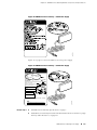
On the SRX210 Services Gateway, each Gigabit Ethernet port and Fast Ethernet port
has two LEDs.Figure 8 on page 20 shows the SRX210 Services Gateway Ethernet
port LEDs.
Figure 8: SRX210 Services Gateway Ethernet Port LEDs
20
■
SRX210 Services Gateway LEDs
Chapter 2: SRX210 Services Gateway Hardware Components and Specifications
NOTE: The numbers in Figure 8 on page 20 correspond to the numbers in Table 12
on page 21.
Table 12 on page 21 describes the built-in Ethernet port LEDs.
Table 12: SRX210 Services Gateway Built-In Ethernet Port LEDs
Number
Function
Color
State
Description
1
TX/RX/LINK
LED
Green
Blinking
Link is active. Data
communication is taking place.
Steady
Link is active. No data
communication is taking place.
Unlit
Off
Link is inactive.
Green
Steady
PoE (Power over Ethernet) is on
and the connected power device
is receiving power.
Yellow
Steady
PoE (Power over Ethernet) is on,
but the connected power device
is not receiving power (device
fault or not enough power).
Unlit
Off
PoE is off.
2
PoE LED
NOTE: The PoE LED is enabled only on the Power over Ethernet (PoE) model of the
SRX210 Services Gateway. For non-PoE models, the PoE LED remains off.
Voice Interface Port LED
On the SRX210 Services Gateway, each Voice Interface (FXO and FXS) port has a
single LED indicating the status.
Figure 9 on page 22 shows the SRX210 Services Gateway Voice Interface port LEDs.
SRX210 Services Gateway LEDs
■
21
SRX210 Services Gateway Hardware Guide
Figure 9: SRX210 Services Gateway Voice Interface Port LEDs
Table 13 on page 22 describes the Voice Interface port LEDs.
Table 13: SRX210 Services Gateway Voice Interface Port LEDs
LED
Color
State
Description
Voice Interface
LEDs
Off
Unlit
Port is inactive.
Green
Steady
Port is connected and active.
Amber
On
Port is active and not ready
for data communication.
Green
Blinking
Port is active and data
communication is taking
place.
Red
Blinking
Port is initializing.
(FXS1, FXS2,
FXO1, and FXO2)
NOTE: The Voice Interface
port LEDs glow red (blinking)
while initializing. If there is an
error, the LEDs remain red;
otherwise, change to green.
Red
Related Topics
22
■
Steady
Port has detected a hardware
initialization failure.
■
SRX210 Services Gateway Specifications on page 7
■
SRX210 Services Gateway Front Panel and Back Panel Views (Low Memory, High
Memory and PoE Version) on page 10
■
SRX210 Services Gateway with Integrated Convergence Services Front Panel
and Back Panel Views on page 12
■
SRX210 Services Gateway Built-In Interfaces on page 14
■
SRX210 Services Gateway Boot Devices and Dual-Root Partitioning Scheme on
page 23
SRX210 Services Gateway LEDs
Chapter 2: SRX210 Services Gateway Hardware Components and Specifications
■
SRX210 Services Gateway Cooling System on page 24
■
SRX210 Services Gateway Power Supply on page 26
SRX210 Services Gateway Boot Devices and Dual-Root Partitioning Scheme
This topic includes the following sections:
■
Boot Devices on page 23
■
Dual-Root Partitioning Scheme on page 23
Boot Devices
The SRX210 Services Gateway can boot from two devices:
■
Internal NAND flash (default; always present)
■
USB storage key (alternate)
Dual-Root Partitioning Scheme
The dual-root partitions allow the SRX210 Services Gateways to remain functional if
there is file system corruption and facilitate easy recovery of the corrupted file system.
The dual-root partitioning scheme keeps the primary and backup JUNOS Software
images in two independently bootable root partitions. If the primary root partition
becomes corrupted, the system will be able to boot from the backup JUNOS Software
image located in the other root partition and remain fully functional.
When the SRX210 Services Gateway powers up, it tries to boot the JUNOS Software
from the default storage media. If the device fails to boot from the default storage
media, it tries to boot from the alternate storage media. With the dual-root partitioning
scheme, the SRX210 Services Gateway first tries to boot the JUNOS Software from
the primary root partition and then from the backup root partition on the default
storage media. If both primary and backup root partitions of a media fail to boot,
then the device tries to boot from the next available type of storage media. The
SRX210 Services Gateway remains fully functional even if it boots the JUNOS Software
from the backup root partition of storage media.
NOTE: SRX210 Services Gateway that ship from the factory with JUNOS Software
Release 10.0 is formatted with the dual-root partitioning scheme.
Existing SRX210 Services Gateways that are running JUNOS Software Release 9.6 or
earlier use the single-root partitioning scheme.
While upgrading these devices to JUNOS Software Release 10.0, you can choose to
format the storage media with dual-root partitions (strongly recommended) or retain
the existing single-root partitioning.
SRX210 Services Gateway Boot Devices and Dual-Root Partitioning Scheme
■
23
SRX210 Services Gateway Hardware Guide
For instructions on upgrading to JUNOS Software Release 10.0, see the SRX Series
Release Notes.
Related Topics
■
SRX210 Services Gateway Specifications on page 7
■
SRX210 Services Gateway Front Panel and Back Panel Views (Low Memory, High
Memory and PoE Version) on page 10
■
SRX210 Services Gateway with Integrated Convergence Services Front Panel
and Back Panel Views on page 12
■
SRX210 Services Gateway Power Supply on page 26
SRX210 Services Gateway Cooling System
The cooling system for the SRX210 Services Gateway with Low Memory, High
Memory, or Power over Ethernet (PoE) includes one fixed fan. The SRX210 Services
Gateway with Integrated Convergence Services has two fixed fans.
The cooling system works from side-to-rear in the services gateway chassis. The fans
draw air through vents along the left and right sides of the chassis and exhaust the
air through the rear side of the chassis.
The airflow produced by the fans keeps device components within the acceptable
temperature range.
Figure 10 on page 25 shows the airflow through the chassis for the SRX210 Services
Gateway with Low Memory, High Memory, and PoE models.
24
■
SRX210 Services Gateway Cooling System
Chapter 2: SRX210 Services Gateway Hardware Components and Specifications
Figure 10: Airflow Through the Chassis (SRX210 Services Gateway with Low Memory,
High Memory, and PoE Models)
Air flow
Rear
g031140
Fan
Front
Figure 11 on page 26 shows the airflow through the chassis for the SRX210 Services
Gateway with Integrated Convergence Services model.
SRX210 Services Gateway Cooling System
■
25
SRX210 Services Gateway Hardware Guide
Figure 11: Airflow Through the Chassis (SRX210 Services Gateway with Integrated
Convergence Services Model)
Air flow
Fan
Fan
g031171
Rear
Front
Related Topics
■
SRX210 Services Gateway Specifications on page 7
■
SRX210 Services Gateway Front Panel and Back Panel Views (Low Memory, High
Memory and PoE Version) on page 10
■
SRX210 Services Gateway with Integrated Convergence Services Front Panel
and Back Panel Views on page 12
■
SRX210 Services Gateway Power Supply on page 26
SRX210 Services Gateway Power Supply
The power supply for the SRX210 Services Gateway is external. You must use the
power supply adapter provided by Juniper Networks to provide power to the services
gateway.
Figure 12 on page 27 shows the label for the 48 V power supply.
26
■
SRX210 Services Gateway Power Supply
Chapter 2: SRX210 Services Gateway Hardware Components and Specifications
g037542
Figure 12: SRX210 Services Gateway — 48 V Power Supply
Figure 13 on page 27 shows the label for the 54 V power supply.
Figure 13: SRX210 Services Gateway — 54 V Power Supply
150W AD/DC ADAPTER
JUNIPER P/N:740-027642
MODEL
: EADP-150NB B
REV: S3
INPUT
: 100-240V ~ 2.5A(2,5A) 50-60Hz
OUTPUT
: +54V
2.78A(2,78A)
EFFICIENCY LEVEL :
CAUTION:
FOR USE WITH INFORMATION TECHNOLOGY EQUIPMENT.
ATTENTION:
UTILISER AVEC DU MATERIEL INFORMATIQUE SEULEMENT.
Endast för kontorsmaskin.
Apparaten skall añslutas till jordat uttag
när den ansluts till ett nätverk.
NOM
NYCE
R33030
V85
10
N17908
MADE IN CHINA
DCGP ZL
Related Topics
g037543
S/N:
■
SRX210 Services Gateway Specifications on page 7
■
SRX210 Services Gateway Front Panel and Back Panel Views (Low Memory, High
Memory and PoE Version) on page 10
SRX210 Services Gateway Power Supply
■
27
SRX210 Services Gateway Hardware Guide
28
■
■
SRX210 Services Gateway with Integrated Convergence Services Front Panel
and Back Panel Views on page 12
■
SRX210 Services Gateway Boot Devices and Dual-Root Partitioning Scheme on
page 23
■
SRX210 Services Gateway Cooling System on page 24
■
Monitoring the SRX210 Services Gateway Power System on page 125
SRX210 Services Gateway Power Supply
Chapter 3
SRX210 Services Gateway 3G
ExpressCard
This chapter includes the following topics:
■
SRX210 Services Gateway 3G ExpressCard Overview on page 29
■
Installing the 3G ExpressCard in the SRX210 Services Gateway ExpressCard
Slot on page 32
■
SRX210 Services Gateway 3G ExpressCard Basic CLI Commands on page 33
SRX210 Services Gateway 3G ExpressCard Overview
This topic provides an overview of the SRX210 Services Gateway 3G ExpressCard
and it includes the following sections:
■
Introduction on page 29
■
Supported Modem Types on page 29
■
Using the 3G ExpressCard on page 30
■
Key Features on page 30
■
Physical Specifications on page 31
Introduction
Wireless WAN access is becoming widely available and comparably priced to ISDN
and DSL. The SRX210 Services Gateway provides support for a wireless interface as
a backup for primary interfaces such as Gigabit Ethernet or Fast Ethernet.
To facilitate wireless connectivity, the SRX210 Services Gateway has a 3G port with
an ExpressCard interface on the back panel. For more information on SRX210
Services Gateway back panel, see “SRX210 Services Gateway Front Panel and Back
Panel Views (Low Memory, High Memory and PoE Version)” on page 10.
Supported Modem Types
Table 14 on page 30 lists the modem types supported on the SRX210 Services
Gateway.
SRX210 Services Gateway 3G ExpressCard Overview
■
29
SRX210 Services Gateway Hardware Guide
Table 14: Juniper Networks Wireless Modems Supported by the SRX210 Services Gateway
Wireless Cards
Release Supported
EXPCD-3G-CDMA-V: 3G EVDO ExpressCard for Verizon Wireless. Currently
available from Juniper Networks.
JUNOS Software Releases 9.6, 10.0, 10.1, and
10.2
EXPCD-3G-CDMA-S: 3G EVDO ExpressCard for Sprint. Currently available from
Juniper Networks.
JUNOS Software Releases 9.6, 10.0, 10.1, and
10.2
Sierra Wireless AirCard 880E/881E supporting Global System for Mobile
Communications (GSM) High-Speed Packet Access (HSPA) ExpressCard. Not
available from Juniper Networks.
JUNOS Software Releases 9.5 and 9.6
Sierra Wireless AirCard AC501/AC502 supporting Global System for Mobile
Communications (GSM) High-Speed Packet Access (HSUPA). Not available from
Juniper Networks.
JUNOS Software Releases 10.1 and 10.2
Using the 3G ExpressCard
To use the ExpressCard, you plug it into the 3G ExpressCard slot, enabling you to
dial a wireless call to the 3G wireless service provider network, which acts as an
Internet gateway.
To use the 3G ExpressCard as a backup interface, you can use the dialer feature
available in the services gateway.
For more information on configuring the 3G ExpressCard, see the JUNOS Software
Interfaces and Routing Configuration Guide.
NOTE: The SRX210 Services Gateway does not support hot insertion and removal
of the 3G ExpressCard.
Key Features
The 3G ExpressCard provides the following key features:
30
■
■
Onboard Subscriber Identity Module (SIM) — All GSM cards have an onboard
SIM. The service provider populates this SIM with the subscriber service
parameters.
■
Onboard nonvolatile RAM (NVRAM) — The Code Division Multiple Access (CDMA)
cards have an onboard NVRAM.
■
Activation of new cards through the CLI — You can activate CDMA ExpressCards
from the JUNOS CLI.
■
Unlocking ExpressCards — You can unlock GSM ExpressCards from the JUNOS
CLI. If the SIM is locked, you need to unlock it before making a call.
SRX210 Services Gateway 3G ExpressCard Overview
Chapter 3: SRX210 Services Gateway 3G ExpressCard
NOTE: Only GSM cards support locking and unlocking of the SIM.
■
Interface support — The ExpressCard interface supports the IP over PPP interface
from the network through the wireless link.
■
Dial-out support — The dialer interface can place calls and has multiple features
such as dial-backup, dialer-watchlist, and dialer-filter. The dialer interface can
use the ExpressCard to support this feature.
NOTE: The 3G ExpressCard does not support the dial-in feature.
■
Card information availability — You can use CLI commands to obtain information
on the ExpressCard, such as type, version, wireless status, and user profiles.
■
Security
■
GSM cards support PIN lock to prevent unauthorized access and use of the
wireless account.
■
You can use the CLI request commands to lock or unlock the SIM card.
■
You have the option to store the PIN code you provide in the services gateway
configuration , so that the SIM can be unlocked without user intervention
on each reboot or reset on the box.
NOTE: Currently all GSM cards support PIN-protected SIMs.
Physical Specifications
Table 15 on page 31 lists the physical parameters of the 3G ExpressCard.
Table 15: 3G ExpressCard Physical Specifications
Specification
Value
Type
Standard ExpressCard with 34 modules
ExpressCard width
34 mm (1.33 in.)
Thickness
5 mm (0.19 in.)
Connector pins
26
Max power consumption
1.3 watts
SRX210 Services Gateway 3G ExpressCard Overview
■
31
SRX210 Services Gateway Hardware Guide
Table 15: 3G ExpressCard Physical Specifications (continued)
Related Topics
Specification
Value
Voltage supply
■
3.3V (primary source)
■
1.5V (secondary source)
■
SRX210 Services Gateway 3G ExpressCard Basic CLI Commands on page 33
■
Installing the 3G ExpressCard in the SRX210 Services Gateway ExpressCard Slot
on page 32
■
SRX210 Services Gateway Front Panel and Back Panel Views (Low Memory, High
Memory and PoE Version) on page 10
Installing the 3G ExpressCard in the SRX210 Services Gateway ExpressCard Slot
TIP: Placing the SRX210 Services Gateway on a flat, level surface, with the Juniper
Networks logo facing up, will make it easier to align and insert the 3G ExpressCard
in the ExpressCard slot.
CAUTION: The SRX210 Services Gateway does not support hot insertion and removal
of the 3G ExpressCard.
To install the 3G ExpressCard in the ExpressCard slot on the SRX210 Services
Gateway:
1.
2.
32
■
Align the 3G ExpressCard as follows:
■
Ensure that the 3G ExpressCard is parallel with the surface on which the
SRX210 Services Gateway is placed.
■
Ensure that the center of the 3G ExpressCard is aligned with the center of
the ExpressCard slot on the SRX210 Services Gateway.
Study Figure 14 on page 33, which shows installation of the 3G ExpressCard on
the SRX210 Services Gateway.
Installing the 3G ExpressCard in the SRX210 Services Gateway ExpressCard Slot
Chapter 3: SRX210 Services Gateway 3G ExpressCard
Figure 14: Installing 3G ExpressCard in the SRX210 Services Gateway
3.
Related Topics
Insert the 3G ExpressCard slowly and firmly into the ExpressCard slot until the
3G ExpressCard is engaged in the slot as follows:
■
The 3G ExpressCard is designed to fit tightly in the slot. You will encounter
two points of resistance while inserting the 3G ExpressCard into the slot.
Use firm pressure as you insert the card.
■
You will encounter the first point of resistance when you begin to insert the
3G ExpressCard. After you align the 3G ExpressCard, lift the card slightly
and use firm pressure to slide it into the slot.
■
When you have partially inserted the 3G ExpressCard, you will encounter
the second point of resistance. Use additional pressure to finish inserting
the 3G ExpressCard into the slot.
■
SRX210 Services Gateway 3G ExpressCard Overview on page 29
■
SRX210 Services Gateway 3G ExpressCard Basic CLI Commands on page 33
SRX210 Services Gateway 3G ExpressCard Basic CLI Commands
Table 16 on page 33 lists the basic CLI commands for operating the 3G ExpressCard
on the SRX210 Services Gateway.
The 3G wireless interface uses the prefix cl in the syntax cl-slot-number/0/port number.
Table 16: SRX210 Services Gateway 3G ExpressCard Basic CLI Commands
Action
Command
Checks the status of the 3G ExpressCard.
show modem wireless interface cl-0/0/8
show interfaces terse
CDMA ExpressCards
SRX210 Services Gateway 3G ExpressCard Basic CLI Commands
■
33
SRX210 Services Gateway Hardware Guide
Table 16: SRX210 Services Gateway 3G ExpressCard Basic CLI Commands (continued)
Action
Command
Activates the CDMA ExpressCard
request modem wireless activate
IOTA — Activates Internet-based over
air provisioning .
■
■
Manual activation — Requires manual
entry of the required information.
■
OTASP — Activates over the air service
provisioning.
■
request modem wireless activate iota cl-0/0/8
■
request modem wireless activate manual
cl-0/0/8 msl MSL value mdn MDN value imsi
IMSI value sid SID value nid NID value
sip-user-id SIP ID sip-password SIP_PASSWORD
■
request modem wireless activate otasp
cl-0/0/8 dial-string calling number
GSM
Unlocks the GSM SIM.
request modem wireless gsm sim-unlock cl-0/0/8
pin
Unlocks the SIM automatically on reboot
set interfaces cl-0/0/ 8 cellular-options gsm-options
sim-unlock-code
Recovers the SIM from the Pin Unlock Key
(PUK) state
request modem wireless gsm sim-unblock cl-0/0/8
puk puk numberpin new pin number
When you attempt to unlock the SIM, if you
enter a wrong PIN three times in a row, the
SIM enters the PUK state.
NOTE: You must obtain the PUK value from your
cellular service provider.
Changes the PIN on the SIM.
request modem wireless gsm change-pin cl-0/0/8
old-pin current pin new-pin new pin
For more information about configuring the 3G wireless interface, see JUNOS Software
Interfaces and Routing Configuration Guide.
Related Topics
34
■
■
SRX210 Services Gateway 3G ExpressCard Overview on page 29
■
Installing the 3G ExpressCard in the SRX210 Services Gateway ExpressCard Slot
on page 32
SRX210 Services Gateway 3G ExpressCard Basic CLI Commands
Chapter 4
SRX210 Services Gateway Power over
Ethernet Support
This chapter includes the following topics:
■
SRX210 Services Gateway PoE Overview on page 35
■
Configuring PoE Functionality on the SRX210 Services Gateway on page 37
SRX210 Services Gateway PoE Overview
This topic includes the following sections:
■
Introduction on page 35
■
PoE Classes and Power Ratings on page 36
Introduction
Power over Ethernet (PoE) is the implementation of the IEEE 802.3 AF and IEEE802.3
AT standards that allow both data and electric power to pass over a copper Ethernet
LAN cable.
The SRX210 Services Gateway supports PoE on four ports, which supply electric
power over the same ports that are used to connect network devices. PoE ports allow
you to plug in devices that require both network connectivity and electric power,
such as VoIP and IP phones and wireless access points.
You can configure the gateway to act as power sourcing equipment for devices
connected on the designated ports.
Table 17 on page 35 lists the SRX210 Services Gateway PoE specifications.
Table 17: SRX210 Services Gateway PoE Specifications
Power Management Schemes
Values
Supported standards
■
IEEE 802.3 AF (PoE)
■
IEEE802.3 AT (PoE+)
■
Legacy (pre-standards)
SRX210 Services Gateway PoE Overview
■
35
SRX210 Services Gateway Hardware Guide
Table 17: SRX210 Services Gateway PoE Specifications (continued)
Power Management Schemes
Values
Supported ports
The following ports support PoE:
■
ge-0/0/0
■
ge-0/0/1
■
fe-0/0/2
■
fe-0/0/3
Total PoE power sourcing capacity
50 watts
Per-port power limit
30 watts
Power management modes
■
Static: power allocated for each interface
can be configured
■
Class: power allocated for interfaces is
decided based on the class of powered
device connected
The IEEE 802.3 AF (PoE) functionality is supported on SRX210 Services Gateway
PoE models that have power supply of 48V. The IEEE802.3 AT (PoE+) functionality
is supported on SRX210 Services Gateway PoE models that have power supply of
54V. For more information, see “Adjusting the Power Supply Adapter Tray for the
SRX210 Services Gateway for Rack-Mount Installation” on page 70.
NOTE:
■
The PoE+ functionality is available from JUNOS Software Release 10.2 or later.
■
The PoE+ functionality is available only if your gateway is using 54V power
supply. You can order the 54V power supply from Juniper Networks. Contact
your Juniper Networks customer service representative for more information.
PoE Classes and Power Ratings
A powered device is classified based on the maximum power that it draws across
all input voltages and operational modes. When the class-based power management
mode is configured on the services gateway, power is allocated by taking into account
the maximum power ratings defined for the different classes of devices.
Table 18 on page 37 lists the classes and their power ratings as specified by the IEEE
802.3 AF standard.
36
■
SRX210 Services Gateway PoE Overview
Chapter 4: SRX210 Services Gateway Power over Ethernet Support
Table 18: PoE Classes and Power Ratings on the SRX210 Services Gateway
Related Topics
Class
Maximum Power Level Output from the PoE Port
0
15.4 watts
1
4.0 watts
2
7.0 watts
3
15.4 watts
4
30.0 watts
■
SRX210 Services Gateway Description on page 3
■
SRX210 Services Gateway Specifications on page 7
■
SRX210 Services Gateway Front Panel and Back Panel Views (Low Memory, High
Memory and PoE Version) on page 10
■
SRX210 Services Gateway Built-In Interfaces on page 14
■
SRX210 Services Gateway LEDs on page 18
■
Mini-Physical Interface Modules on the SRX210 Services Gateway
■
SRX210 Services Gateway 3G ExpressCard Overview on page 29
Configuring PoE Functionality on the SRX210 Services Gateway
To enable the Power over Ethernet (PoE) feature support on your SRX210 Services
Gateway, you must configure the services gateway.
You can configure PoE using the CLI configuration editor.
For more details on configuring PoE, see the JUNOS Software Interfaces and Routing
Configuration Guide.
Related Topics
■
SRX210 Services Gateway Description on page 3
■
SRX210 Services Gateway Specifications on page 7
■
SRX210 Services Gateway Front Panel and Back Panel Views (Low Memory, High
Memory and PoE Version) on page 10
■
SRX210 Services Gateway Built-In Interfaces on page 14
■
SRX210 Services Gateway LEDs on page 18
■
Mini-Physical Interface Modules on the SRX210 Services Gateway
Configuring PoE Functionality on the SRX210 Services Gateway
■
37
SRX210 Services Gateway Hardware Guide
38
■
Configuring PoE Functionality on the SRX210 Services Gateway
Chapter 5
SRX210 Services Gateway with Integrated
Convergence Services
This chapter includes the following topics:
■
About the SRX210 Services Gateway with Integrated Convergence
Services on page 39
■
Understanding the Functions of the SRX210 Services Gateway with Integrated
Convergence Services on page 41
■
SRX210 Services Gateway Integrated Convergence Services
Interoperability on page 42
■
Configuring the SRX210 Services Gateway with Integrated Convergence
Services on page 43
About the SRX210 Services Gateway with Integrated Convergence Services
This topic includes following sections:
■
Basic Functions on page 40
■
Supported Features on page 40
■
Common Deployment Scenarios on page 41
About the SRX210 Services Gateway with Integrated Convergence Services
■
39
SRX210 Services Gateway Hardware Guide
Basic Functions
The availability of hardware and software for voice and data transmission on the
same device is called integrated convergence services.
SRX210 Services Gateway with Integrated Convergence Services implements a media
gateway and a survivable call server. The SRX210 Services Gateway with Integrated
Convergence Services integrates voice and data capabilities and provides a generic
SIP-based voice over IP (VoIP) Media Gateway (SVMG) capability for local public
switched telephone network (PSTN) and legacy analog/fax/phone connectivity. This
feature enables standard phones to be used for voice calls over the Internet.
The SRX210 Services Gateway with Integrated Convergence Services performs the
following basic functions:
■
Bridges the VoIP network to the PSTN so that calls can be made from remote
SIP and PSTN phones and routed to local analog telephones, fax machines, and
local SIP phones behind the media gateway.
■
Assumes the call routing role as a survivable call server for local SIP or Analog
phones, in the event of loss of WAN connections.
■
Supports emergency calling (E911) by providing the mechanism to detect
emergency calls from local VoIP phones and passes these calls to the PSTN when
detected.
■
Provides power failover support for one analog phone and PSTN FXO port.
Supported Features
The SRX210 Services Gateway with Integrated Convergence Services also offers the
following additional features:
40
■
■
Digit manipulation for remapping digits
■
Caller ID support for detection and transmission of caller information (for U.S.
standards)
■
Call waiting for SIP and analog phones in which the user is alerted about a
pending, incoming call
■
Call hold and resume in which SIP calls may be placed on hold and resumed by
the SIP phone user
■
Call waiting and call forwarding
■
Local auto attendant with a standard workflow, allowing the caller to enter an
extension number to reach the call destination
■
Voice mail answering and retrieval through PSTN digit mapping
About the SRX210 Services Gateway with Integrated Convergence Services
Chapter 5: SRX210 Services Gateway with Integrated Convergence Services
Common Deployment Scenarios
The SRX210 Services Gateway with Integrated Convergence Services is deployed in
following environments:
Related Topics
■
Enterprises that deploy VoIP in their headquarters and want to enable VoIP
functionality for their branch offices.
■
Services providers (SPs) who provide VoIP services to their business customers.
■
Branch sites currently using a local key system or PBX that want to utilize SIP
trunking services
■
Understanding the Functions of the SRX210 Services Gateway with Integrated
Convergence Services on page 41
■
SRX210 Services Gateway Integrated Convergence Services Interoperability on
page 42
■
Configuring the SRX210 Services Gateway with Integrated Convergence Services
on page 43
■
SRX210 Services Gateway with Integrated Convergence Services Front Panel
and Back Panel Views on page 12
Understanding the Functions of the SRX210 Services Gateway with Integrated
Convergence Services
SRX210 Services Gateway with Integrated Convergence Services functions as follows:
■
Analog telephones and fax machines are directly connected to the SRX210
Services Gateway with Integrated Convergence Services through Foreign Exchange
Station (FXS) interfaces.
■
The telephone exchange or PSTN central office is directly connected to the
SRX210 Services Gateway with Integrated Convergence Services through Foreign
Exchange Office (FXO) interfaces.
■
The media gateway converts analog signals from FXS and FXO ports and digital
TDM signals from T1/E1 ports to VoIP packets and sends them to the network
after processing through JUNOS software secure routing and firewall flows.
Similarly, the media gateway receives forwarded VoIP packets from the network,
and converts them into analog signal or digital TDM signals and send them across
the appropriate interface.
■
The media gateway also provides power failover support in the event of power
loss by providing a hardware relay between the built-in FXS2 port and FXO1
port, which automatically connects the two ports when the media gateway loses
power.
Understanding the Functions of the SRX210 Services Gateway with Integrated Convergence Services
■
41
SRX210 Services Gateway Hardware Guide
NOTE: The 2-Port FXS/2-Port FXO Mini-PIM and the 4-Port FXO Mini-PIM does not
support failover relay between any of the FXS and FXO ports.
■
Telephony interface expansion available through Mini-PIM interface card option
includes a 2–Port FXS/2–Port FXO Mini-PIM, 4–Port FXO Mini-PIM, and an IP
Flex T1/E1 Mini-PIM with initial support for T1-CAS (loopstart only).
NOTE: For more information on Mini-PIMs, see the SRX Series Services Gateways for
the Branch Physical Interface Modules Hardware Guide.
Related Topics
■
About the SRX210 Services Gateway with Integrated Convergence Services on
page 39
■
SRX210 Services Gateway Integrated Convergence Services Interoperability on
page 42
■
Configuring the SRX210 Services Gateway with Integrated Convergence Services
on page 43
SRX210 Services Gateway Integrated Convergence Services Interoperability
The SRX210 Services Gateway with Integrated Convergence Services aligns with the
open convergence architecture and supports different brands of call servers and SIP
phones.
Table 19 on page 42 summarizes the SIP phones, softphones, and analog devices
supported by SRX210 Services Gateway with Integrated Convergence Services.
Table 19: SRX210 Services Gateway Integrated Convergence Services Interoperability
Phone Types
Devices
SIP phones
■
Avaya 4600 and 9600 series
■
Polycom 300 and 500 series
■
Snom 300 series
■
Microsoft OCS-compatible phones
■
Cisco Unified SIP phones 7960 and 7961
■
SNOM 360
■
Microsoft OCS client
■
X-Lite EyeBeam Mini-SIP
■
Avaya one-x
Softphones
42
■
SRX210 Services Gateway Integrated Convergence Services Interoperability
Chapter 5: SRX210 Services Gateway with Integrated Convergence Services
Table 19: SRX210 Services Gateway Integrated Convergence Services
Interoperability (continued)
Related Topics
Phone Types
Devices
Analog devices
Any analog device including the phones, FAX
machines, PBX or key systems, voice mail or
answering machine, and analog paging systems.
SIP call servers
■
Avaya CM 5.2 with SES
■
Avaya ASM (Aura 1.x)
■
Microsoft OCS R1 and R2
■
Asterisk 1.6.x (Open Source)
■
About the SRX210 Services Gateway with Integrated Convergence Services on
page 39
■
Understanding the Functions of the SRX210 Services Gateway with Integrated
Convergence Services on page 41
■
Configuring the SRX210 Services Gateway with Integrated Convergence Services
on page 43
Configuring the SRX210 Services Gateway with Integrated Convergence Services
To enable voice support on your SRX210 Services Gateway with Integrated
Convergence Services, you must configure the services gateway.
You can configure the voice functionality using:
■
CLI configuration editor
■
J-Web configuration editor
For more information on configuring voice, see the Integrated Convergence Services
Configuration and Administration Guide for SRX Series Services Gateways.
Related Topics
■
■
Understanding the Functions of the SRX210 Services Gateway with Integrated
Convergence Services on page 41
■
SRX210 Services Gateway Integrated Convergence Services Interoperability on
page 42
Configuring the SRX210 Services Gateway with Integrated Convergence Services
■
43
SRX210 Services Gateway Hardware Guide
44
■
Configuring the SRX210 Services Gateway with Integrated Convergence Services
Chapter 6
SRX210 Services Gateway Mini-Physical
Interface Modules
This chapter includes the following topic:
■
SRX210 Services Gateway Mini-Physical Interface Modules on page 45
SRX210 Services Gateway Mini-Physical Interface Modules
The SRX210 Services Gateway supports Mini-Physical Interface Modules (Mini-PIMs).
A Mini-PIM is a network interface card (NIC) that is installed on the services gateway
to provide physical connections to a LAN or a WAN. The Mini-PIM receives incoming
packets from the network and transmits outgoing packets to the network. The
Mini-PIMs supported on the services gateway are field-replaceable. The field
replaceable Mini-PIMs are removable and insertable into the device. You can install
a Mini-PIM into the Mini-PIM slot available on the front panel of the services gateway
chassis.
For more information about supported Mini-PIMs, including how to install and
configure Mini-PIMs, refer to the SRX Series Services Gateways for the Branch Physical
Interface Modules Hardware Guide.
CAUTION: The Mini-PIMs available on the SRX210 Services Gateway are not
hot-swappable. You need to power off the device before removing or installing
Mini-PIMs.
Related Topics
■
SRX210 Services Gateway Description on page 3
■
SRX210 Services Gateway Specifications on page 7
■
SRX210 Services Gateway Hardware Features on page 4
■
SRX210 Services Gateway Built-In Interfaces on page 14
SRX210 Services Gateway Mini-Physical Interface Modules
■
45
SRX210 Services Gateway Hardware Guide
46
■
SRX210 Services Gateway Mini-Physical Interface Modules
Part 2
Setting Up the SRX210 Services Gateway
■
Preparing the Site for the SRX210 Services Gateway Installation on page 49
■
Installation Overview for the SRX210 Services Gateway on page 57
■
Required Tools and Parts for Installing and Maintaining the SRX210 Services
Gateway on page 59
■
Unpacking the SRX210 Services Gateway on page 61
■
Preparing the SRX210 Services Gateway for Installation on page 65
■
Installing the SRX210 Services Gateway on page 69
■
Connecting, Grounding, and Powering On the SRX210 Services
Gateway on page 81
■
SRX210 Services Gateway Autoinstallation on page 89
■
Connecting the SRX210 Services Gateway to Management Devices on page 91
■
Performing Initial Software Configuration on the SRX210 Services
Gateway on page 101
Setting Up the SRX210 Services Gateway
■
47
SRX210 Services Gateway Hardware Guide
48
■
Setting Up the SRX210 Services Gateway
Chapter 7
Preparing the Site for the SRX210
Services Gateway Installation
This chapter provides a checklist to help you prepare your site for installation of the
SRX210 Services Gateway. Read this section to make sure that your site has the
proper operating environment and equipment.
This chapter includes the following topics:
■
Site Preparation Checklist for the SRX210 Services Gateway on page 49
■
General Site Guidelines for Installing the SRX210 Services Gateway on page 51
■
SRX210 Services Gateway Cabinet Requirements on page 51
■
SRX210 Services Gateway Rack Requirements on page 52
■
Clearance Requirements for Airflow and Hardware Maintenance of the SRX210
Services Gateway on page 54
■
SRX210 Services Gateway Electrical and Power Requirements on page 55
Site Preparation Checklist for the SRX210 Services Gateway
The checklist in Table 20 on page 49 summarizes the tasks you need to perform
when preparing a site for installing the SRX210 Services Gateway.
Table 20: Site Preparation Checklist for the SRX210 Services Gateway Installation
Item or Task
Additional Information
Date
and
Notes
Environment
Verify that environmental factors such as
temperature and humidity do not exceed device
tolerances.
“SRX210 Services Gateway
Specifications” on page 7
Power
Site Preparation Checklist for the SRX210 Services Gateway
■
49
SRX210 Services Gateway Hardware Guide
Table 20: Site Preparation Checklist for the SRX210 Services Gateway
Installation (continued)
Item or Task
■
Measure distance between external power
sources and device installation site.
■
Locate sites for connection of system
grounding.
■
Calculate the power consumption and
requirements.
Additional Information
Date
and
Notes
“SRX210 Services Gateway Site
Electrical Wiring Guidelines” on
page 157
“SRX210 Services Gateway Power
Specifications and Requirements”
on page 158
Rack Installation
■
Verify that your rack meets the minimum
requirements.
■
Plan rack location, including required space
clearances.
■
Secure the rack to the floor and building
structure.
“SRX210 Services Gateway Rack
Requirements” on page 52
Cabinet Installation
■
Verify that your cabinet meets the
minimum requirements.
■
Plan the cabinet location, including required
space clearances.
“SRX210 Services Gateway Cabinet
Requirements” on page 51
Wall Installation
■
Verify that the area selected meets the
minimum requirements.
■
Verify that you have the required hardware
to proceed with the installation.
“Preparing the SRX210 Services
Gateway for Wall-Mount
Installation” on page 68
Desktop Installation
■
Verify that the area selected meets the
minimum requirements.
■
Plan the installation location, including
required space clearances and airflow
requirements.
“Preparing the SRX210 Services
Gateway for Desk-Mount
Installation” on page 67
Cables
Related Topics
50
■
■
Acquire cables and connectors.
■
Review the maximum distance allowed for
each cable. Choose the length of cable
based on the distance between the
hardware components being connected.
■
Plan the cable routing and management.
“Interface Cable and Wire
Specifications for the SRX210
Services Gateway” on page 161
■
SRX210 Services Gateway Specifications on page 7
■
General Site Guidelines for Installing the SRX210 Services Gateway on page 51
Site Preparation Checklist for the SRX210 Services Gateway
Chapter 7: Preparing the Site for the SRX210 Services Gateway Installation
■
Installation Overview for the SRX210 Services Gateway on page 57
■
SRX210 Services Gateway Cabinet Requirements on page 51
■
SRX210 Services Gateway Rack Requirements on page 52
■
Clearance Requirements for Airflow and Hardware Maintenance of the SRX210
Services Gateway on page 54
General Site Guidelines for Installing the SRX210 Services Gateway
The following precautions help you plan an acceptable operating environment for
your SRX210 Services Gateway and avoid environmentally caused equipment failures:
■
For the cooling system to function properly, the airflow around the chassis must
be unrestricted. Allow sufficient clearance between the front and back of the
chassis and adjacent equipment. Ensure that there is adequate circulation in the
installation location.
■
Follow the ESD procedures to avoid damaging equipment. Static discharge can
cause components to fail completely or intermittently over time.
■
Ensure that the blank Mini-PIM panel is installed in the empty slot to prevent
any interruption or reduction in the flow of air across internal components.
NOTE: Install the device only in restricted areas, such as dedicated equipment rooms
and equipment closets, in accordance with Articles 110–16, 110–17, and 110–18
of the National Electrical Code, ANSI/NFPA 70.
Related Topics
■
SRX210 Services Gateway Specifications on page 7
■
SRX210 Services Gateway Safety Requirements, Warnings, and Guidelines on
page 69
■
SRX210 Services Gateway Cabinet Requirements on page 51
■
SRX210 Services Gateway Rack Requirements on page 52
■
Site Preparation Checklist for the SRX210 Services Gateway on page 49
■
Clearance Requirements for Airflow and Hardware Maintenance of the SRX210
Services Gateway on page 54
SRX210 Services Gateway Cabinet Requirements
The SRX210 Services Gateway can be installed in a standard 800 mm (31.5 in.) or
larger enclosed cabinet. Table 21 on page 52 provides the details on cabinet size,
clearance, and airflow requirements.
General Site Guidelines for Installing the SRX210 Services Gateway
■
51
SRX210 Services Gateway Hardware Guide
Table 21: SRX210 Services Gateway Cabinet Requirements
Cabinet
Requirements
Cabinet size
Specifications
19 in. (48.3 cm) as defined in Cabinets, Racks, Panels, and Associated
Equipment (document number EIA-310–D) published by the Electronics
Industry Association (http://www.eia.org).
You can mount the services gateway horizontally in the cabinet.
Clearance
requirements
■
The cabinet is at least 1 U (1.75 in. or 4.5 cm) high.
■
The outer edges of the mounting brackets extend the width of either
chassis to 19 in. (48.2 cm), and the front of the chassis extends
approximately 0.5 in. (1.27 cm) beyond the mounting brackets.
■
The minimum total clearance inside the cabinet is 30.7 in. (78 cm)
between the inside of the front door and the inside of the rear door.
NOTE: The holes for the mounting brackets chassis are spaced 1.25 in. (3.2
cm) apart, measured from the center of the hole.
Cabinet airflow
requirements
■
Ensure sufficient ventilation through the cabinet is sufficient to prevent
overheating.
■
Ensure adequate cool air supply to dissipate the thermal output of the
device.
■
Install the device as close as possible to the front of the cabinet so that
the cable management system clears the inside of the front door.
Installing the chassis close to the front of the cabinet maximizes the
clearance in the rear of the cabinet for critical airflow.
■
Route and dress all cables to minimize the blockage of airflow to and
from the chassis.
NOTE: A cabinet larger than the minimum required provides better airflow
and reduces the chance of overheating.
Related Topics
■
General Site Guidelines for Installing the SRX210 Services Gateway on page 51
■
Site Preparation Checklist for the SRX210 Services Gateway on page 49
■
SRX210 Services Gateway Rack Requirements on page 52
■
Clearance Requirements for Airflow and Hardware Maintenance of the SRX210
Services Gateway on page 54
SRX210 Services Gateway Rack Requirements
The services gateway can be installed in a rack. Many types of racks are acceptable,
including front-mount racks and four-post (telco) racks.
52
■
SRX210 Services Gateway Rack Requirements
Chapter 7: Preparing the Site for the SRX210 Services Gateway Installation
NOTE: The services gateway cannot be center-mounted in racks.
Table 22 on page 53 provides the details on rack size, clearance, and airflow
requirements.
Table 22: Rack Requirements for the Services Gateway
Rack Requirements
Specifications
Rack Size
A 19 in. (48.3 cm) rack as defined in Cabinets, Racks, Panels, and
Associated Equipment (document number EIA-310-D) published by the
Electronics Industry Association (http://www.eia.org).
Rack Requirements
■
The outer edges of the mounting brackets extend the width of either
chassis to 19 in. (48.3 cm).
■
The front of the chassis extends approximately 0.5 in. (1.27 cm)
beyond the mounting ears.
■
Maximum permissible ambient temperature when two devices are
placed side by side in a 19 in. rack is 40°C.
■
The holes within each rack set are spaced at 1 U [1.75 in. (4.5 cm)].
The device can be mounted in any rack that provides holes or hole
patterns spaced at 1-U [1.75 in. (4.5 cm)] increments.
■
The mounting brackets and front-mount flanges used to attach the
chassis to a rack are designed to fasten to holes spaced at rack
distances of 1 U (1.75 in.).
■
The mounting holes in the mounting brackets provided with the
device are spaced 1.25 in. (3.2 cm) apart (top and bottom mounting
hole).
Spacing of Mounting
Bracket and Flange
Holes
Connecting to the
Building Structure
Related Topics
Always secure the rack in which you are installing the services gateway
to the structure of the building. If your geographical area is subject to
earthquakes, bolt the rack to the floor. For maximum stability, also
secure the rack to ceiling brackets.
■
General Site Guidelines for Installing the SRX210 Services Gateway on page 51
■
Site Preparation Checklist for the SRX210 Services Gateway on page 49
■
SRX210 Services Gateway Cabinet Requirements on page 51
■
Clearance Requirements for Airflow and Hardware Maintenance of the SRX210
Services Gateway on page 54
SRX210 Services Gateway Rack Requirements
■
53
SRX210 Services Gateway Hardware Guide
Clearance Requirements for Airflow and Hardware Maintenance of the SRX210
Services Gateway
When planning the installation site for the SRX210 Services Gateway, you need to
allow sufficient clearance around the rack or cabinet where you are planning to install
the device.
When planning the installation site for the services gateway, consider the following:
■
For the cooling system to function properly, the airflow around the chassis must
be unrestricted.
■
For service personnel to remove and install hardware components, there must
be adequate space at the front and back of the device. Allow at least 24 in. (61
cm) both in front of and behind the device.
■
If you are mounting the device in a rack with other equipment, or if you are
placing it on the desktop near other equipment, ensure that the exhaust from
other equipment does not blow into the intake vents of the chassis.
Table 23 on page 54 provides information on the clearance requirements for
maintaining the optimum airflow and the distances for facilitating easy
maintenance of the device.
Table 23: Clearance Requirements for the Services Gateway
Location
Recommended
Clearance
Front of the chassis
2.5 in. (6.35 cm)
Requirement for Clearance
Space for service personnel to
remove and install hardware
components
NOTE: More space is required for
installing and removing Mini-PIMs.
54
■
Rear of the chassis
2.5 in. (6.35 cm)
Space for service personnel to
remove and install hardware
components
Between front-mounting flange
and rack or cabinet edge
2.5 in. (6.35 cm)
Space for cable management and
organization
Between side of the chassis and
any non-heat-producing surface
such as a wall or cabinet side
2.5 in. (6.35 cm)
Space for the cooling system to
function properly and to maintain
unrestricted airflow around the
chassis
Between side of the chassis and
devices that have fans or
blowers
2.5 in. (6.35 cm)
Space for the cooling system to
function properly and to maintain
unrestricted airflow around the
chassis
Clearance Requirements for Airflow and Hardware Maintenance of the SRX210 Services Gateway
Chapter 7: Preparing the Site for the SRX210 Services Gateway Installation
Related Topics
■
SRX210 Services Gateway Description on page 3
■
General Site Guidelines for Installing the SRX210 Services Gateway on page 51
■
Site Preparation Checklist for the SRX210 Services Gateway on page 49
■
SRX210 Services Gateway Cabinet Requirements on page 51
■
SRX210 Services Gateway Rack Requirements on page 52
SRX210 Services Gateway Electrical and Power Requirements
There are factors you must consider while planning the electrical wiring and power
availability at your site. These factors include the following requirements:
Related Topics
■
Power specifications and requirements for the device
■
Electrical wiring guidelines for the device installation site
■
Power, connection, and power cord specifications for the device
■
Grounding guidelines and specifications for the device
■
SRX210 Services Gateway Site Electrical Wiring Guidelines on page 157
■
SRX210 Services Gateway Power Specifications and Requirements on page 158
■
Site Preparation Checklist for the SRX210 Services Gateway on page 49
SRX210 Services Gateway Electrical and Power Requirements
■
55
SRX210 Services Gateway Hardware Guide
56
■
SRX210 Services Gateway Electrical and Power Requirements
Chapter 8
Installation Overview for the SRX210
Services Gateway
This chapter includes the following topic:
Installation Overview for the SRX210 Services Gateway on page 57
■
Installation Overview for the SRX210 Services Gateway
After you have prepared your installation site, you are ready to unpack and install
the services gateway. It is important to proceed through the installation process as
shown in Table 24 on page 57.
Table 24: Installation Process Order for the SRX210 Services Gateway
Step
Task
For more information, see
1
Review the safety guidelines
explained.
“SRX210 Services Gateway General
Safety Guidelines and Warnings” on
page 133
2
Verify that you have prepared your
site for the installation of the services
gateway using the checklist.
“Site Preparation Checklist for the
SRX210 Services Gateway” on
page 49
3
Unpack the services gateway and
verify that the parts are received.
“Unpacking the SRX210 Services
Gateway” on page 61
4
Prepare the services gateway for
installation.
“Preparing the SRX210 Services
Gateway for Rack-Mount,
Desk-Mount, and Wall-Mount
Installation” on page 65
5
Install the services gateway.
■
Installing the SRX210 Services
Gateway in a Rack on page 71
■
Installing the SRX210 Services
Gateway on a Desk on page 75
■
Installing the SRX210 Services
Gateway on a Wall on page 76
6
Connect cables to external devices.
“Connecting and Organizing Interface
Cables to the SRX210 Services
Gateway” on page 83
Installation Overview for the SRX210 Services Gateway
■
57
SRX210 Services Gateway Hardware Guide
Table 24: Installation Process Order for the SRX210 Services Gateway (continued)
Related Topics
58
■
Step
Task
For more information, see
7
Connect the grounding cables.
“Grounding the SRX210 Services
Gateway” on page 84
8
Power on the services gateway.
“Powering On and Powering Off the
SRX210 Services Gateway” on
page 85
■
Unpacking the SRX210 Services Gateway on page 61
■
General Site Guidelines for Installing the SRX210 Services Gateway on page 51
■
Preparing the SRX210 Services Gateway for Rack-Mount, Desk-Mount, and
Wall-Mount Installation on page 65
Installation Overview for the SRX210 Services Gateway
Chapter 9
Required Tools and Parts for Installing
and Maintaining the SRX210 Services
Gateway
This chapter includes the following topic:
■
Required Tools and Parts for Installing and Maintaining the SRX210 Services
Gateway on page 59
Required Tools and Parts for Installing and Maintaining the SRX210 Services
Gateway
Table 25 on page 59 lists the tools and equipments required to install and maintain
the SRX210 Services Gateway.
Table 25: Required Tools and Parts for Installing and Maintaining the SRX210 Services
Gateway
Task
Tools and Parts
Installing the SRX210 Services
Gateway
■
Phillips (+) screwdriver,
number 1
■
Tie wrap
Related Topic
■
Installing the SRX210
Services Gateway in a
Rack on page 71
■
Installing the SRX210
Services Gateway on a
Desk on page 75
■
Installing the SRX210
Services Gateway on a
Wall on page 76
Connecting the SRX210
Services Gateway
Electrostatic discharge (ESD)
grounding wrist strap
“Connecting the SRX210
Services Gateway to the Power
Supply” on page 81
Grounding the SRX210
Services Gateway
Phillips (+) screwdriver,
number 1
“Grounding the SRX210
Services Gateway” on page 84
Required Tools and Parts for Installing and Maintaining the SRX210 Services Gateway
■
59
SRX210 Services Gateway Hardware Guide
Table 25: Required Tools and Parts for Installing and Maintaining the SRX210 Services
Gateway (continued)
Related Topics
60
■
Task
Tools and Parts
Packing the SRX210 Services
Gateway
■
Blank panel to cover
empty Mini-PIM slot
■
Electrostatic bag or
antistatic mat, for each
component
■
Electrostatic discharge
(ESD) grounding wrist
strap
Related Topic
“Packing the SRX210 Services
Gateway and Components for
Shipment” on page 171
■
Unpacking the SRX210 Services Gateway on page 61
■
Grounding the SRX210 Services Gateway on page 84
■
Connecting the SRX210 Services Gateway to the Power Supply on page 81
■
Packing the SRX210 Services Gateway and Components for Shipment on page 171
Required Tools and Parts for Installing and Maintaining the SRX210 Services Gateway
Chapter 10
Unpacking the SRX210 Services Gateway
This chapter includes the following topics:
■
Unpacking the SRX210 Services Gateway on page 61
■
Verifying Parts Received with the SRX210 Services Gateway on page 61
Unpacking the SRX210 Services Gateway
The SRX210 Services Gateway is shipped in a cardboard carton. The carton also
contains an accessory box and the SRX210 Services Gateway Getting Started Guide.
NOTE: The device is maximally protected inside the shipping carton. Do not unpack
it until you are ready to begin installation.
To unpack the SRX210 Services Gateway:
Related Topics
1.
Open the box in which the device is shipped.
2.
Verify the parts received against the lists in “Verifying Parts Received with the
SRX210 Services Gateway” on page 61.
3.
Store the shipping box and packing material in case you need to return or move
the device at a later time.
■
Required Tools and Parts for Installing and Maintaining the SRX210 Services
Gateway on page 59
■
Verifying Parts Received with the SRX210 Services Gateway on page 61
■
Preparing the SRX210 Services Gateway for Rack-Mount, Desk-Mount, and
Wall-Mount Installation on page 65
■
Installation Overview for the SRX210 Services Gateway on page 57
Verifying Parts Received with the SRX210 Services Gateway
The SRX210 Services Gateway shipment package contains a packing list that includes
all parts and accessories available with the device. Check the parts in the shipment
Unpacking the SRX210 Services Gateway
■
61
SRX210 Services Gateway Hardware Guide
against the items on the packing list. The packing list specifies the part numbers and
descriptions of each part in your order.
If any part is missing, contact your Juniper Networks customer service representative.
A fully configured SRX210 Services Gateway contains the chassis with installed
components, listed in Table 26 on page 62, and an accessory box, which contains
the parts listed in Table 27 on page 62.
NOTE: The parts shipped with your device can vary depending on the configuration
you ordered.
Table 26: Parts List for a Fully Configured SRX210 Services Gateway
Component
■
For Low Memory model (SRX210B):
Quantity
1
SRX210 Services Gateway with 2xGE + 6xFE ports,
1xMini-PIM slot, and base memory (512 MB RAM, 1GB
Flash)
■
For High Memory model (SRX210H):
SRX210 Services Gateway with 2xGE + 6xFE ports,
1xMini-PIM slot, and high memory (1GB RAM, 1GB
Flash)
■
For PoE model (SRX210H-POE):
SRX210 Services Gateway with 2xGE + 6xFE ports,
1xMini-PIM slot, high memory (1GB RAM, 1GB Flash),
4 ports of POE 802.11AT (50 watts across 4 ports)
■
For Voice model (SRX210H-P-MGW):
SRX210 Services Gateway with 2xGE + 6xFE ports,
1xMini-PIM slot, high memory (1GB RAM, 1GB Flash),
4 ports POE (50 watts) and Media Gateway with 2 FXO
and 2 FXS ports
■
Power supply adapter (60 watts for Low Memory and
High Memory models)
■
Power supply adapter (150 watts for PoE and Voice
models)
1
3-Prong Power Cord
1
DB-9 to RJ-45 Adapter, Straight Through, 7 feet
1
Table 27: Accessory Parts List for the SRX210 Services Gateway
62
■
Part
Quantity
Juniper Networks Product Warranty
1
End User License Agreement
1
Verifying Parts Received with the SRX210 Services Gateway
Chapter 10: Unpacking the SRX210 Services Gateway
Table 27: Accessory Parts List for the SRX210 Services Gateway (continued)
Part
Quantity
Quick Start Guide
1
Security Products Safety Guide
1
Juniper Compliance Form Letter
1
Product Registration
1
Tie Wrap
1
NOTE: The mounting kits available for rack, wall, and desk installation of the SRX210
Services Gateway must be ordered separately. Contact your Juniper Networks
customer service representative for more information.
NOTE: The Mini-Physical Interface Modules (Mini-PIMs) are not shipped with the
device. You have to order them separately. Contact your Juniper Networks customer
service representative for more information.
Related Topics
■
Required Tools and Parts for Installing and Maintaining the SRX210 Services
Gateway on page 59
■
Unpacking the SRX210 Services Gateway on page 61
■
Preparing the SRX210 Services Gateway for Rack-Mount, Desk-Mount, and
Wall-Mount Installation on page 65
Verifying Parts Received with the SRX210 Services Gateway
■
63
SRX210 Services Gateway Hardware Guide
64
■
Verifying Parts Received with the SRX210 Services Gateway
Chapter 11
Preparing the SRX210 Services Gateway
for Installation
This chapter includes the following topics:
■
Preparing the SRX210 Services Gateway for Rack-Mount, Desk-Mount, and
Wall-Mount Installation on page 65
■
Preparing the SRX210 Services Gateway for Rack-Mount Installation on page 66
■
Preparing the SRX210 Services Gateway for Desk-Mount Installation on page 67
■
Preparing the SRX210 Services Gateway for Wall-Mount Installation on page 68
Preparing the SRX210 Services Gateway for Rack-Mount, Desk-Mount, and
Wall-Mount Installation
You can mount an SRX210 Services Gateway in a rack, on a desk, or on a wall. See
the following topics for more information:
■
Preparing the SRX210 Services Gateway for Rack-Mount Installation on page 66
■
Preparing the SRX210 Services Gateway for Desk-Mount Installation on page 67
■
Preparing the SRX210 Services Gateway for Wall-Mount Installation on page 68
The mounting kits for rack, wall, and desk installation of the SRX210 Services Gateway
must be ordered separately. Contact your Juniper Networks customer service
representative for more information.
Related Topics
■
Site Preparation Checklist for the SRX210 Services Gateway on page 49
■
Unpacking the SRX210 Services Gateway on page 61
■
Clearance Requirements for Airflow and Hardware Maintenance of the SRX210
Services Gateway on page 54
■
Preparing the SRX210 Services Gateway for Rack-Mount Installation on page 66
■
Preparing the SRX210 Services Gateway for Desk-Mount Installation on page 67
■
Preparing the SRX210 Services Gateway for Wall-Mount Installation on page 68
Preparing the SRX210 Services Gateway for Rack-Mount, Desk-Mount, and Wall-Mount Installation
■
65
SRX210 Services Gateway Hardware Guide
Preparing the SRX210 Services Gateway for Rack-Mount Installation
You can mount an SRX210 Services Gateway on four-post (telco) racks, enclosed
cabinets, and open-frame racks.
NOTE: The SRX210 Services Gateway cannot be center-mounted in racks.
Table 28 on page 66 provides the list of tasks you need to perform before installing
the device.
Table 28: SRX210 Services Gateway Preinstallation Checklist for Rack-Mount
Installation
Task
Additional Information
Verify that the site meets the requirements.
“Site Preparation Checklist for the SRX210
Services Gateway” on page 49
Verify that the racks or cabinets meet the specific
requirements.
“SRX210 Services Gateway Rack
Requirements” on page 52
Place the rack or cabinet in its permanent location,
allowing adequate clearance for airflow and
maintenance, and secure it to the building
structure.
“Clearance Requirements for Airflow and
Hardware Maintenance of the SRX210
Services Gateway” on page 54
Remove the services gateway chassis from the
shipping carton.
“Unpacking the SRX210 Services Gateway”
on page 61
Verify that you have the following parts available
in your rack-mounting kit for the SRX210 Services
Gateway:
■
Rack-mounting brackets
■
Mounting screws
■
Power supply adapter tray with screws
■
Adapter stopper bracket
Adjust the power supply adapter tray.
“Adjusting the Power Supply Adapter Tray
for the SRX210 Services Gateway for
Rack-Mount Installation” on page 70
NOTE: The rack-mounting kit is not shipped with the device and must be ordered
separately.
66
■
Preparing the SRX210 Services Gateway for Rack-Mount Installation
Chapter 11: Preparing the SRX210 Services Gateway for Installation
Related Topics
■
Site Preparation Checklist for the SRX210 Services Gateway on page 49
■
Clearance Requirements for Airflow and Hardware Maintenance of the SRX210
Services Gateway on page 54
■
Unpacking the SRX210 Services Gateway on page 61
■
Preparing the SRX210 Services Gateway for Rack-Mount, Desk-Mount, and
Wall-Mount Installation on page 65
■
Preparing the SRX210 Services Gateway for Desk-Mount Installation on page 67
■
Preparing the SRX210 Services Gateway for Wall-Mount Installation on page 68
Preparing the SRX210 Services Gateway for Desk-Mount Installation
You can mount an SRX210 Services Gateway on a desk or other level surface
horizontally or vertically. The four rubber feet attached to the chassis provide stability.
Table 29 on page 67 provides the list of tasks you need to perform before installing
the device.
Table 29: SRX210 Services Gateway Preinstallation Checklist for Desk-Mount
Installation
Task
Additional Information
Verify that the site meets the requirements.
“Site Preparation Checklist for the SRX210
Services Gateway” on page 49
Place the desk in its permanent location, allowing
adequate clearance for airflow and maintenance,
and secure it to the building structure.
“Clearance Requirements for Airflow and
Hardware Maintenance of the SRX210
Services Gateway” on page 54
Remove the services gateway chassis from the
shipping carton.
“Unpacking the SRX210 Services
Gateway” on page 61
Verify that you have the following parts available in
your desk-mounting kit to mount the SRX210
Services Gateway vertically:
■
Vertical stand
■
Screws
NOTE: If you are mounting the services gateway horizontally on a desk, ensure that
the chassis is attached with the rubber feet.
NOTE: The vertical desk-mounting kit is not shipped with the device and must be
ordered separately.
Preparing the SRX210 Services Gateway for Desk-Mount Installation
■
67
SRX210 Services Gateway Hardware Guide
Related Topics
■
Site Preparation Checklist for the SRX210 Services Gateway on page 49
■
Clearance Requirements for Airflow and Hardware Maintenance of the SRX210
Services Gateway on page 54
■
Unpacking the SRX210 Services Gateway on page 61
■
Preparing the SRX210 Services Gateway for Rack-Mount Installation on page 66
■
Preparing the SRX210 Services Gateway for Wall-Mount Installation on page 68
Preparing the SRX210 Services Gateway for Wall-Mount Installation
You can mount an SRX210 Services Gateway on a wall. The four rubber feet attached
to the chassis provide stability.
Table 30 on page 68 provides the list of tasks you need to perform before installing
the device.
Table 30: SRX210 Services Gateway Preinstallation Checklist for Wall-Mount
Installation
Task
Additional Information
Verify that the site meets the requirements.
“Site Preparation Checklist for the
SRX210 Services Gateway” on page 49
Remove the services gateway chassis from the
shipping carton.
“Unpacking the SRX210 Services
Gateway” on page 61
Verify that you have the following parts available in
your wall-mounting kit to mount the SRX210 Services
Gateway on wall:
■
Wall-mounting brackets
■
Screws
NOTE: The wall-mounting kit is not shipped with the device and must be ordered
separately.
Related Topics
68
■
■
Site Preparation Checklist for the SRX210 Services Gateway on page 49
■
Unpacking the SRX210 Services Gateway on page 61
■
Preparing the SRX210 Services Gateway for Rack-Mount Installation on page 66
■
Preparing the SRX210 Services Gateway for Desk-Mount Installation on page 67
Preparing the SRX210 Services Gateway for Wall-Mount Installation
Chapter 12
Installing the SRX210 Services Gateway
This chapter includes the following topics:
■
SRX210 Services Gateway Safety Requirements, Warnings, and
Guidelines on page 69
■
SRX210 Services Gateway Installation on page 69
■
Replacing or Installing Mini-Physical Interface Modules in the SRX210 Services
Gateway on page 78
SRX210 Services Gateway Safety Requirements, Warnings, and Guidelines
To avoid harm to yourself or the device as you install and maintain it, follow the
guidelines for working with and near electrical equipment, as well as the safety
procedures for working with devices. For a discussion of how to make the installation
site a safe environment and a list of safety warnings, see the Appendix for Safety
and Regulatory Compliance Information.
NOTE: Providing an exhaustive set of guidelines for working with electrical equipment
is beyond the scope of this guide.
Related Topics
■
General Site Guidelines for Installing the SRX210 Services Gateway on page 51
■
Required Tools and Parts for Installing and Maintaining the SRX210 Services
Gateway on page 59
■
Preparing the SRX210 Services Gateway for Rack-Mount, Desk-Mount, and
Wall-Mount Installation on page 65
■
General Site Guidelines for Installing the SRX 210 Services Gateway
SRX210 Services Gateway Installation
You can install the SRX210 Services Gateway in a rack, on a desk, or on a wall. The
device includes rubber feet for desk and wall mounting. The mounting brackets are
optional accessories.
SRX210 Services Gateway Safety Requirements, Warnings, and Guidelines
■
69
SRX210 Services Gateway Hardware Guide
Install the device as appropriate for your site using one of the following procedures:
■
Adjusting the Power Supply Adapter Tray for the SRX210 Services Gateway for
Rack-Mount Installation on page 70
■
Installing the SRX210 Services Gateway in a Rack on page 71
■
Installing the SRX210 Services Gateway on a Desk on page 75
■
Installing the SRX210 Services Gateway on a Wall on page 76
Adjusting the Power Supply Adapter Tray for the SRX210 Services Gateway for Rack-Mount
Installation
This topic provides details on the power supply adapters provided with different
models of the SRX210 Services Gateway and the procedure for adjusting the power
supply adapter tray to hold the power supply adapter.
The following power supply adapters are provided with the SRX210 Services Gateway:
■
60-watt power supply adapter for the SRX210 Services Gateway Low Memory
and High Memory models
■
150-watt power supply adapter for the SRX210 Services Gateway with PoE and
the SRX210 Services Gateway with Integrated Convergence Services
To adjust the power supply adapter tray:
■
To accommodate the 60-watt power supply, use the two 420–028535 screws to
attach the adapter stopper brackets at the point on the chassis marked B.
Figure 15 on page 70 shows the adjustments to the power supply adapter tray
required for the 60-watt power supply.
Figure 15: Adjusting the Power Supply Adapter Tray to Accommodate the 60-Watt
Power Supply
70
■
1.
Locations for the adapter stopper brackets in the power supply adapter tray
2.
Fully configured power supply adapter tray
Adjusting the Power Supply Adapter Tray for the SRX210 Services Gateway for Rack-Mount Installation
Chapter 12: Installing the SRX210 Services Gateway
■
To accommodate the 150-watt power supply, use the 420–028535 screw to
attach the adapter stopper bracket at the point on the chassis marked A.
Figure 16 on page 71 shows the adjustments to the power supply adapter tray
required for the 150-watt power supply.
Figure 16: Adjusting the Power Supply Adapter Tray to Accommodate the 150-Watt
Power Supply
Related Topics
1.
Locations for the adapter stopper brackets in the power supply adapter tray
2.
Fully configured power supply adapter tray
■
Preparing the SRX210 Services Gateway for Rack-Mount, Desk-Mount, and
Wall-Mount Installation on page 65
■
Preparing the SRX210 Services Gateway for Rack-Mount Installation on page 66
Installing the SRX210 Services Gateway in a Rack
You can front-mount the SRX210 Services Gateway in a rack. Many types of racks
are acceptable, including four-post (telco) racks, enclosed cabinets, and open-frame
racks. For more information about the type of rack or cabinet the SRX210 Services
Gateway can be installed into, see “SRX210 Services Gateway Rack Requirements”
on page 52.
NOTE: The rack-mounting kit is not shipped with the device and must be ordered
separately.
Installing the SRX210 Services Gateway in a Rack
■
71
SRX210 Services Gateway Hardware Guide
NOTE:
■
If you are installing multiple devices in one rack, install the lowest one first and
proceed upward in the rack.
■
Ensure that the rubber feet from the base of the chassis are removed for rack
installation.
To install the device in a rack:
1.
Position a mounting bracket on each side of the chassis as shown in Figure 17
on page 72.
Figure 17: Installation of SRX210 Services Gateway in a Rack — Positioning Mounting
Brackets
Table 31 on page 72 lists the parts used for installing the SRX210 Services
Gateway on the rack. The numbers in Figure 17 on page 72 correspond to the
numbers in Table 31 on page 72.
Table 31: SRX210 Services Gateway Rack Installation Parts
S.No
Part
1
Mounting brackets
2
Screws (mounting bracket)
3
Power supply adapter tray
4
Adapter stopper bracket
2.
72
■
Use a number-1 Phillips screwdriver to install the screws that secure the mounting
brackets and power supply adapter tray to the chassis as shown in Figure 18 on
page 73.
Installing the SRX210 Services Gateway in a Rack
Chapter 12: Installing the SRX210 Services Gateway
Figure 18: SRX210 Services Gateway Rack Installation — Securing Mounting Brackets
and Power Supply Adapter Tray
3.
Place the power supply adapter in the tray as shown in Figure 19 on page 73.
Figure 19: SRX210 Services Gateway Rack Installation — Positioning Power Supply
Adapter Tray
4.
Have one person grasp the sides of the device, lift it, and position it in the rack.
5.
Align the bottom hole in each mounting bracket with a hole in each rack rail as
shown in Figure 20 on page 74, making sure the chassis is level.
Installing the SRX210 Services Gateway in a Rack
■
73
SRX210 Services Gateway Hardware Guide
Figure 20: SRX210 Services Gateway Rack Installation — Hanging the Services
Gateway in a Rack
Related Topics
74
■
6.
Have a second person install a mounting screw into each of the two aligned
holes. Use a number-3 Phillips screwdriver to tighten the screws.
7.
Install the second screw in each mounting bracket.
8.
Verify that the mounting screws on one side of the rack are aligned with the
mounting screws on the opposite side and that the device is level.
■
SRX210 Services Gateway General Safety Guidelines and Warnings on page 133
■
Required Tools and Parts for Installing and Maintaining the SRX210 Services
Gateway on page 59
■
Preparing the SRX210 Services Gateway for Rack-Mount Installation on page 66
■
Adjusting the Power Supply Adapter Tray for the SRX210 Services Gateway for
Rack-Mount Installation on page 70
■
Installing the SRX210 Services Gateway on a Desk on page 75
■
Installing the SRX210 Services Gateway on a Wall on page 76
Installing the SRX210 Services Gateway in a Rack
Chapter 12: Installing the SRX210 Services Gateway
Installing the SRX210 Services Gateway on a Desk
Follow these guidelines when installing the device on a desk:
■
You can install the SRX210 Services Gateway on a desk, table, or other level
surface.
■
The device is shipped with the rubber feet attached. The rubber feet are necessary
to stabilize the device on the desk.
■
You can install the device in a horizontal or vertical position.
■
The vertical position requires the vertical installation kit, which consists of a
vertical installation stand with the rubber feet attached.
NOTE: The desk-mounting kit is not shipped with the device and must be ordered
separately.
To install the device in a horizontal position:
The horizontal position is the standard installation position and does not require the
vertical installation kit.
1.
Make sure that the rubber feet are attached to the chassis.
2.
Place the device on a desk with the Juniper Networks logo embossed on the top
cover facing up.
To install the device in a vertical position:
1.
Place the device on a flat and level surface with the Juniper Networks logo
embossed on the top cover facing up.
2.
Attach the vertical stand to the right side of the chassis using the specified screws
as shown in Figure 21 on page 75.
Figure 21: SRX210 Services Gateway Desk Installation — Attaching Vertical Stand
3.
Place the chassis vertically on the desk with the stand resting on the desk as
shown in Figure 22 on page 76.
Installing the SRX210 Services Gateway on a Desk
■
75
SRX210 Services Gateway Hardware Guide
Figure 22: SRX210 Services Gateway Desk Installation — Placing the Services
Gateway on Desk
Related Topics
■
SRX210 Services Gateway General Safety Guidelines and Warnings on page 133
■
Required Tools and Parts for Installing and Maintaining the SRX210 Services
Gateway on page 59
■
Preparing the SRX210 Services Gateway for Desk-Mount Installation on page 67
■
Installing the SRX210 Services Gateway in a Rack on page 71
■
Installing the SRX210 Services Gateway on a Wall on page 76
Installing the SRX210 Services Gateway on a Wall
You can install the SRX210 Services Gateway on a wall.
NOTE: The wall-mounting kit is not shipped with the device and must be ordered
separately.
To install the device on a wall:
76
■
Installing the SRX210 Services Gateway on a Wall
Chapter 12: Installing the SRX210 Services Gateway
1.
Place the device on a flat and level surface with Juniper Networks logo embossed
on the top cover facing up. Ensure that rubber feet are attached to the bottom
of the chassis.
2.
Position a mounting bracket on each side of the chassis as shown in Figure 23
on page 77.
Figure 23: SRX210 Services Gateway Wall Installation — Attaching Mounting Brackets
Table 32 on page 77 lists the parts used for installing the SRX210 Services
Gateway on a wall. The numbers in Figure 23 on page 77 correspond to the
numbers in Table 32 on page 77.
Table 32: SRX210 Services Gateway Wall Installation Parts
Numbers
Part
1
Mounting brackets
2
Screws (mounting bracket)
3.
Use a number-1 Phillips screwdriver to install the screws that secure the mounting
brackets to the chassis.
4.
If you are using wall anchors to support the chassis, install two pairs of anchors
on the wall with the mounting brackets attached.
5.
Have one person grasp the sides of the device, lift it, and position it on the wall.
6.
Have a second person install two pairs of mounting screws through the bracket
holes on either side of the device to secure it to the wall.
7.
Verify that the mounting screws on one side are aligned with the mounting
screws on the opposite side and that the device is level (see Figure 24 on
page 78).
Installing the SRX210 Services Gateway on a Wall
■
77
SRX210 Services Gateway Hardware Guide
Figure 24: SRX210 Services Gateway Wall Installation — Hanging the Services
Gateway on Wall
Related Topics
■
SRX210 Services Gateway General Safety Guidelines and Warnings on page 133
■
Required Tools and Parts for Installing and Maintaining the SRX210 Services
Gateway on page 59
■
Preparing the SRX210 Services Gateway for Rack-Mount Installation on page 66
■
Adjusting the Power Supply Adapter Tray for the SRX210 Services Gateway for
Rack-Mount Installation on page 70
■
Installing the SRX210 Services Gateway on a Desk on page 75
■
Installing the SRX210 Services Gateway on a Wall on page 76
Replacing or Installing Mini-Physical Interface Modules in the SRX210 Services
Gateway
Mini-Physical Interface Modules (Mini-PIMs) are circuit boards that you can install in
a device for enhanced functionality based on your requirements. They enable you
to easily add or change physical interfaces on a device.
78
■
Replacing or Installing Mini-Physical Interface Modules in the SRX210 Services Gateway
Chapter 12: Installing the SRX210 Services Gateway
The Mini-Physical Interface Module (Mini-PIM) slot is covered with a blank faceplate
to maintain proper airflow through the services gateway. Before installing the
Mini-PIM, you must remove the faceplate.
See the SRX Series Services Gateways for the Branch Physical Interface Modules
Hardware Guide for information about installing Mini-PIMs.
NOTE: The Mini-PIMs available on the SRX210 Services Gateway are not
hot-swappable. You need to power off the device before removing or installing
Mini-PIMs.
Related Topics
■
SRX210 Services Gateway Installation Safety Guidelines and Warnings on page 138
■
Installing the SRX210 Services Gateway on a Desk on page 75
■
Installing the SRX210 Services Gateway on a Wall on page 76
■
Installing the SRX210 Services Gateway in a Rack on page 71
Replacing or Installing Mini-Physical Interface Modules in the SRX210 Services Gateway
■
79
SRX210 Services Gateway Hardware Guide
80
■
Replacing or Installing Mini-Physical Interface Modules in the SRX210 Services Gateway
Chapter 13
Connecting, Grounding, and Powering On
the SRX210 Services Gateway
This chapter includes the following topics:
■
Connecting the SRX210 Services Gateway to the Power Supply on page 81
■
Connecting and Organizing Interface Cables to the SRX210 Services
Gateway on page 83
■
Grounding the SRX210 Services Gateway on page 84
■
Powering On and Powering Off the SRX210 Services Gateway on page 85
Connecting the SRX210 Services Gateway to the Power Supply
To connect the device to the power supply:
CAUTION: Before connecting the device to the power supply, attach an ESD strap
to an ESD point and place the other end of the strap around your bare wrist.
NOTE: If you are installing your services gateway on a desk, ensure that your device
is adequately grounded using the grounding point on the back panel of the chassis.
1.
Plug the DC connector end of the power cable into the power connector on the
back of the device (see Figure 25 on page 82).
2.
Plug the AC adapter end of the power cable into an AC power outlet.
Connecting the SRX210 Services Gateway to the Power Supply
■
81
SRX210 Services Gateway Hardware Guide
Figure 25: Connecting the SRX210 Services Gateway to the Power Supply
NOTE: The device must be connected to earth ground during normal operation. The
protective earthing terminal on the rear of the chassis is provided to connect the
device to ground.
CAUTION: We recommend using a surge protector for the power connection.
NOTE: Use the cable tie holder to secure the power cord on to the power supply
point.
NOTE: We strongly recommend that you use only the 3-pin power cord supplied
with your services gateway. If you are using a 2-pin power cord, then ensure that
your device is adequately grounded using the grounding point available on back
panel of chassis.
Related Topics
82
■
■
Required Tools and Parts for Installing and Maintaining the SRX210 Services
Gateway on page 59
■
Grounding the SRX210 Services Gateway on page 84
■
Connecting and Organizing Interface Cables to the SRX210 Services Gateway
on page 83
■
SRX210 Services Gateway General Safety Guidelines and Warnings on page 133
Connecting the SRX210 Services Gateway to the Power Supply
Chapter 13: Connecting, Grounding, and Powering On the SRX210 Services Gateway
Connecting and Organizing Interface Cables to the SRX210 Services Gateway
You can connect the interfaces installed in the services gateway to various network
media. Each type of interface on the services gateway uses a particular medium to
transmit data. You must configure each network interface before it can operate on
the device.
To connect and organize an interface cable to the device:
Related Topics
1.
Have ready a length of the type of cable used by the interface.
2.
Insert the cable connector into the cable connector port on the interface faceplate.
3.
Arrange network cables as follows to prevent them from dislodging or developing
stress points:
■
Secure cables so that they are not supporting their own weight as they hang
to the floor.
■
Place excess cable out of the way in neatly coiled loops.
■
Use fasteners to maintain the shape of cable loops.
■
Connecting the SRX210 Services Gateway to the Power Supply on page 81
■
Grounding the SRX210 Services Gateway on page 84
■
Interface Cable and Wire Specifications for the SRX210 Services Gateway on
page 161
■
SRX210 Services Gateway Installation Safety Guidelines and Warnings on page 138
Connecting and Organizing Interface Cables to the SRX210 Services Gateway
■
83
SRX210 Services Gateway Hardware Guide
Grounding the SRX210 Services Gateway
To meet safety and electromagnetic interference (EMI) requirements and to ensure
proper operation, you must adequately ground the SRX210 Services Gateway before
connecting power.
Figure 26 on page 84 illustrates connecting a grounding cable to the services gateway.
Figure 26: Grounding the SRX210 Services Gateway
You ground the device by connecting a grounding cable to earth ground and then
attaching it to the chassis grounding points using one 6-32 UNC screw.
Table 33 on page 84 lists the specifications of the grounding cable used with the
device.
Table 33: Grounding Cable Specifications for the Services Gateway
Grounding Requirement
Specification
Grounding cable
14 AWG single-strand wire cable
Amperage of grounding cable
Up to 4 A
Grounding lug
Ring-type, vinyl-insulated TV14-6R lug or
equivalent
CAUTION: Before device installation begins, a licensed electrician must attach a cable
lug to the grounding and power cables that you use. A cable with an incorrectly
attached lug can damage the device (for example, by causing a short circuit).
84
■
Grounding the SRX210 Services Gateway
Chapter 13: Connecting, Grounding, and Powering On the SRX210 Services Gateway
To ground the device:
1.
Connect the grounding cable to a proper earth ground.
2.
Verify that a licensed electrician has attached the cable lug to the grounding
cable.
3.
Place the grounding cable lug over the grounding point on the upper rear of the
chassis.
4.
Secure the grounding cable lug to the grounding point with the screw.
5.
Dress the grounding cable and verify that it does not touch or block access to
the services gateway components and that it does not cause anyone to trip on
it.
NOTE: The device should be permanently connected to ground during normal
operation.
Related Topics
■
Connecting the SRX210 Services Gateway to the Power Supply on page 81
■
Connecting and Organizing Interface Cables to the SRX210 Services Gateway
on page 83
■
SRX210 Services Gateway Grounding Specifications on page 159
■
Powering On and Powering Off the SRX210 Services Gateway on page 85
■
SRX210 Services Gateway General Safety Guidelines and Warnings on page 133
Powering On and Powering Off the SRX210 Services Gateway
This topic describes the following procedures:
1. Powering On the SRX210 Services Gateway on page 85
2. Powering Off the SRX210 Services Gateway on page 86
3. Resetting the SRX210 Services Gateway on page 87
Powering On the SRX210 Services Gateway
To power on the services gateway:
1.
Ensure that you have connected the power supply to the device.
2.
Insert the plug of the power supply adapter into an AC power source receptacle.
3.
Turn on the power to the AC power receptacle.
The device starts automatically as the power supply completes its startup sequence.
The Power LED lights up during startup and remains on steadily when the device is
operating normally.
Powering On and Powering Off the SRX210 Services Gateway
■
85
SRX210 Services Gateway Hardware Guide
NOTE: After the power supply is turned on, it can take up to 60 seconds for status
indicators—such as the Status and Power LEDs—to show that the power supply is
functioning normally.
NOTE: It is recommended to issue the CLI command request system power-off when
you want to power off the device immediately after the device is powered on.
Powering Off the SRX210 Services Gateway
You can power off the services gateway in one of the following ways:
■
Graceful shutdown — Press and release the Power button. The device begins
gracefully shutting down the operating system and then powers itself off.
■
Immediate shutdown — Press the Power button and hold it for more than ten
seconds. The device immediately powers itself off without shutting down the
operating system.
NOTE: Do not press the Power button while the device is shutting down.
WARNING: Use the graceful shutdown method to halt, power off, or reboot the
services gateway. Use the immediate shutdown method as a last resort to recover
the services gateway if the services gateway operating system is not responding to
the graceful shutdown method.
CAUTION: Immediate shutdown can result in data loss and corruption of the file
system.
86
■
Powering Off the SRX210 Services Gateway
Chapter 13: Connecting, Grounding, and Powering On the SRX210 Services Gateway
NOTE: To remove power completely from the device, unplug the AC power cord or
switch off the power source.
After powering off a power supply, wait at least 10 seconds before turning it back
on. After powering on a power supply, wait at least 10 seconds before turning it off.
The Power button on the services gateway is a standby power switch.
If you press the Power button to power off the device when it is still connected to a
power source, 12 V (Low Memory and High Memory models) /48 V (PoE and Voice
models) power will still be available in the chassis and the device will be fully powered
off.
TIP: When you are powering off the device, the system displays the following
message: Turning the system power off. You can now safely remove the power cable
to completely disconnect the power from the device.
NOTE: You can use the request system reboot CLI command to schedule a reboot
of the services gateway using request system reboot.
For more information about halting, powering off, or rebooting the services gateway
using CLI, see the JUNOS Software Administration Guide.
Resetting the SRX210 Services Gateway
The Reset Config button located at the front panel of the SRX210 Services Gateway
removes the current configuration and resets the device to the default configuration.
The button is recessed in the front panel to prevent it from being pressed accidentally.
NOTE: Pressing and holding the Reset Config button for 15 seconds or more deletes
all configurations on the device and loads and commits the factory configuration.
Related Topics
■
Connecting the SRX210 Services Gateway to the Power Supply on page 81
■
Grounding the SRX210 Services Gateway on page 84
■
SRX210 Services Gateway Front Panel and Back Panel Views (Low Memory, High
Memory and PoE Version) on page 10
■
Using the Reset Config Button on the SRX210 Services Gateway on page 126
■
SRX210 Services Gateway LEDs on page 18
Resetting the SRX210 Services Gateway
■
87
SRX210 Services Gateway Hardware Guide
88
■
Resetting the SRX210 Services Gateway
Chapter 14
SRX210 Services Gateway
Autoinstallation
This chapter includes the following topic:
■
SRX210 Services Gateway Autoinstallation Overview on page 89
SRX210 Services Gateway Autoinstallation Overview
The autoinstallation process begins any time a services gateway is powered on and
cannot locate a valid configuration file in the internal flash. Typically, a configuration
file is unavailable when a services gateway is powered on for the first time or if the
configuration file is deleted from the internal flash. The autoinstallation feature
enables you to deploy multiple services gateways from a central location in the
network.
If you are setting up many devices, autoinstallation can help automate the
configuration process by loading configuration files onto new or existing devices
automatically over the network. You can use either the J-Web configuration editor
or the CLI configuration editor to configure a device for autoinstallation.
For the autoinstallation process to work, you must store one or more host-specific
or default configuration files on a configuration server in the network and have a
service available—typically Dynamic Host Configuration Protocol (DHCP)—to assign
an IP address to the services gateway.
Autoinstallation takes place automatically when you connect an Ethernet port on a
new services gateway to the network and power on the device. To simplify the
process, you can explicitly enable autoinstallation on a device and specify a
configuration server, an autoinstallation interface, and a protocol for IP address
acquisition.
For more information about configuring autoinstallation, see the JUNOS Software
Administration Guide.
Related Topics
■
Connecting the SRX210 Services Gateway to the Power Supply on page 81
■
Grounding the SRX210 Services Gateway on page 84
■
Powering On and Powering Off the SRX210 Services Gateway on page 85
■
SRX210 Services Gateway Basic Connectivity Overview
SRX210 Services Gateway Autoinstallation Overview
■
89
SRX210 Services Gateway Hardware Guide
90
■
SRX210 Services Gateway Autoinstallation Overview
Chapter 15
Connecting the SRX210 Services Gateway
to Management Devices
This chapter includes the following topics:
■
Connecting an SRX210 Services Gateway to the J-Web Interface on page 91
■
Connecting an SRX210 Services Gateway to the CLI Locally on page 95
■
Connecting an SRX210 Services Gateway to the CLI Remotely on page 96
■
Connecting the Modem at the SRX210 Services Gateway End on page 97
■
Connecting the Modem to the Console Port on the SRX210 Services
Gateway on page 98
■
Connecting to the CLI at the User End for the SRX210 Services
Gateway on page 99
Connecting an SRX210 Services Gateway to the J-Web Interface
If you plan to use the J-Web interface to configure the SRX210 Services Gateway,
you must connect through one of the built-in Ethernet management ports.
When the services gateway is powered on for the first time, the system looks for a
DHCP server. If it does not find one, the system assigns an IP address within the
192.168.1.0/24 subnetwork to any devices connected to the system.
To connect to the J-Web interface through any of the ports ge-0/0/1 or fe-0/0/2 to
fe-0/0/7 on the services gateway, see Figure 27 on page 92.
Connecting an SRX210 Services Gateway to the J-Web Interface
■
91
SRX210 Services Gateway Hardware Guide
Figure 27: Connecting to the Ethernet Port on an SRX210 Services Gateway
92
■
Connecting an SRX210 Services Gateway to the J-Web Interface
g031118
Chapter 15: Connecting the SRX210 Services Gateway to Management Devices
Connecting an SRX210 Services Gateway to the J-Web Interface
■
93
SRX210 Services Gateway Hardware Guide
To connect to the Ethernet port:
1.
From the management device you use to access the J-Web interface (such as a
PC or a laptop), verify that the address of the port you connect to is set to one
of the following values:
■
Ethernet address on the 192.168.1.0/24 subnetwork other than 192.168.1.1
■
Ethernet address from a DHCP server
2.
Plug one end of the CAT-5e (Ethernet cable) into the Ethernet port on the
management device.
3.
Connect the other end of the Ethernet cable to any of the built-in Ethernet ports
ge-0/0/1 or fe-0/0/2 to fe-0/0/7 on the services gateway.
4.
Wait until the Status LED on the front panel of the services gateway turns solid
green.
5.
Turn on the power to the management device. The services gateway assigns an
IP address to the management device within the 192.168.1.0/24 subnetwork
if the management device is configured to use DHCP.
NOTE: After connecting the management device to the services gateway, the DHCP
server process on the services gateway will assign an IP address automatically to the
management device. Ensure that the management device acquires an IP address on
the 192.168.1.0/24 subnetwork (other than 192.168.1.1) from the device.
6.
From the management device, open a Web browser and enter the IP address
192.168.1.1 in the address field if the management device is configured using
the DHCP.
7.
Configure basic settings for your services gateway.
NOTE: You must manually configure the IP address for the management port you
are using before you save your initial configuration. When you save the configuration
for the first time, you will lose the connection to the services gateway if you have
not manually configured the IP address. If you lose the connection through the
management interface, you must connect through the Console port.
Related Topics
94
■
■
Performing Initial Software Configuration on the SRX210 Services Gateway Using
the J-Web Interface on page 107
■
Connecting an SRX210 Services Gateway to the CLI Locally on page 95
■
SRX210 Services Gateway Software Configuration Overview on page 101
■
SRX210 Services Gateway Secure Web Access Overview on page 111
Connecting an SRX210 Services Gateway to the J-Web Interface
Chapter 15: Connecting the SRX210 Services Gateway to Management Devices
Connecting an SRX210 Services Gateway to the CLI Locally
If you plan to use the CLI to configure the SRX210 Services Gateway, you must
connect through the console port, as shown in Figure 28 on page 95.
Figure 28: Connecting to the Console Port on an SRX210 Services Gateway
NOTE: Figure 28 on page 95 shows a connection to a local management device. A
remote connection to the services gateway through a modem requires the cable and
connector shown (provided in the services gateway accessory box), plus a DB-9
female to DB-25 male (or similar) adapter for your modem, which you must purchase
separately.
To connect to the CLI using a local management device through the console port on
the services gateway:
1.
Turn off power to the services gateway.
2.
Turn off power to the management device, such as a PC or laptop computer,
that you are using to access the CLI.
3.
Plug one end of the Ethernet cable supplied with your services gateway into the
RJ-45 to DB-9 serial port adapter supplied with your services gateway (see Figure
28 on page 95).
4.
Plug the RJ-45 to DB-9 serial port adapter into the serial port on the management
device (see Figure 28 on page 95).
5.
Connect the other end of the Ethernet cable to the console port on the services
gateway (see Figure 28 on page 95).
6.
Turn on the power to the management device.
Connecting an SRX210 Services Gateway to the CLI Locally
■
95
SRX210 Services Gateway Hardware Guide
7.
Start your asynchronous terminal emulation application (such as Microsoft
Windows HyperTerminal) and select the appropriate COM port to use (for
example, COM1).
8.
Configure the port settings shown in Table 34 on page 96.
Table 34: Port Settings when Connecting to Console Port
Port Settings
Value
Bits per second
9600
Data bits
8
Parity
None
Stop bits
1
Flow control
None
9.
Power on the services gateway by pressing the Power button on the front panel.
10. Verify that the Power LED on the front panel turns green.
The terminal emulation screen on your management device displays the startup
sequence. When the services gateway has finished starting up, a login prompt
appears.
11. Log in as the user root. No password is required at initial connection, but you
must assign a root password before committing any configuration settings.
Related Topics
■
Connecting an SRX210 Services Gateway to the CLI Remotely on page 96
■
Performing Initial Software Configuration on the SRX210 Services Gateway Using
the CLI on page 104
■
Connecting an SRX210 Services Gateway to the J-Web Interface on page 91
■
SRX210 Services Gateway Software Configuration Overview on page 101
■
SRX210 Services Gateway Secure Web Access Overview on page 111
Connecting an SRX210 Services Gateway to the CLI Remotely
You can connect an SRX210 Services Gateway to the CLI from a remote location
through two dial-up modems:
■
A modem that is connected to the console port on the services gateway
■
A second modem connected to a remote management device
The modem connection allows you to remotely perform the same console operations
you can perform locally.
96
■
Connecting an SRX210 Services Gateway to the CLI Remotely
Chapter 15: Connecting the SRX210 Services Gateway to Management Devices
Related Topics
■
Connecting an SRX210 Services Gateway to the CLI Locally on page 95
■
Performing Initial Software Configuration on the SRX210 Services Gateway Using
the CLI on page 104
■
Connecting an SRX210 Services Gateway to the J-Web Interface on page 91
■
SRX210 Services Gateway Software Configuration Overview on page 101
■
SRX210 Services Gateway Secure Web Access Overview on page 111
Connecting the Modem at the SRX210 Services Gateway End
NOTE: These instructions use Hayes-compatible modem commands to configure the
modem. If your modem is not Hayes-compatible, refer to the documentation for
your modem and enter the equivalent modem commands.
To configure the modem on the services gateway end:
1.
Connect the modem to a PC or laptop computer.
2.
Power on the modem.
3.
From the PC or laptop computer, start your asynchronous terminal emulation
application (such as Microsoft Windows HyperTerminal) and select the COM port
to which the modem is connected (for example, COM1).
4.
Configure the port settings shown in Table 35 on page 97.
Table 35: Port Settings to Configure the Modem on the Services Gateway End
Port Settings
Value
Bits per second
9600
Data bits
8
Parity
None
Stop bits
1
Flow control
None
5.
In the HyperTerminal window, enter AT.
For more information on the AT commands, see the JUNOS Software
Administration Guide.
An OK response verifies that the modem can communicate successfully with the
COM port on the PC or laptop.
6.
Configure the modem to answer a call on the first ring by entering ATS0=1.
Connecting the Modem at the SRX210 Services Gateway End
■
97
SRX210 Services Gateway Hardware Guide
Related Topics
7.
Configure the modem to accept modem control DTR signals by entering AT&D1.
8.
Disable flow control by entering AT&K0.
9.
Save modem settings by entering AT&W.
■
Connecting the Modem to the Console Port on the SRX210 Services Gateway on
page 98
■
Connecting to the CLI at the User End for the SRX210 Services Gateway on
page 99
■
SRX210 Services Gateway Software Configuration Overview on page 101
Connecting the Modem to the Console Port on the SRX210 Services Gateway
To connect the dial-up modem to the console port on the services gateway:
1.
Turn off power to the services gateway.
2.
Turn off power to the modem.
3.
Plug one end of the Ethernet cable supplied with your services gateway into the
console port on the services gateway.
4.
Plug the other end of the CAT-5e (Ethernet cable) into the RJ-45 to DB-9 serial
port adapter supplied with your services gateway.
5.
Connect the serial port adapter to a separately purchased DB-9 female to DB-25
male adapter or other adapter appropriate for your modem.
6.
Plug the modem adapter into the DB-25 connector on the modem.
7.
Connect the modem to your telephone network.
8.
Turn on the power to the modem.
9.
Power on the services gateway by pressing the Power button on the front panel.
Verify that the Power LED on the front panel turns green.
NOTE: Most modems have an RS-232 DB-25 connector. You must separately purchase
an adapter to connect your modem to the RJ-45 to DB-9 adapter and the Ethernet
cable supplied with the services gateway.
Related Topics
98
■
■
Connecting the Modem at the SRX210 Services Gateway End on page 97
■
Connecting to the CLI at the User End for the SRX210 Services Gateway on
page 99
■
SRX210 Services Gateway Software Configuration Overview on page 101
Connecting the Modem to the Console Port on the SRX210 Services Gateway
Chapter 15: Connecting the SRX210 Services Gateway to Management Devices
Connecting to the CLI at the User End for the SRX210 Services Gateway
To remotely connect to the CLI through a dial-up modem connected to the console
port on the services gateway:
1.
Connect a modem at your remote location to a management device such as a
PC or laptop computer.
2.
Start your asynchronous terminal emulation application (such as Microsoft
Windows HyperTerminal) on the PC or laptop computer.
3.
Select the COM port to which the modem is connected (for example, COM1).
4.
Configure the port settings shown in Table 36 on page 99.
Table 36: Port Settings for Connecting CLI at User End
Port Setting
Value
Bits per second
9600
Data bits
8
Parity
None
Stop bits
1
Flow control
None
5.
In the HyperTerminal window, enter AT.
For more information on the AT commands, see the JUNOS Software
Administration Guide.
An OK response verifies that the modem can communicate successfully with the
COM port on the PC or laptop.
6.
Dial the modem that is connected to the console port on the services gateway
by entering ATDT remote-modem-number. For example, if the number of the
modem connected to the console port on the services gateway is
0013033033030, enter ATDT 0013033033030.
The services gateway login prompt appears.
Related Topics
7.
Log in as the user root. No password is required at initial connection, but you
must assign a root password before committing any configuration settings.
■
Connecting the Modem at the SRX210 Services Gateway End on page 97
■
Connecting the Modem to the Console Port on the SRX210 Services Gateway on
page 98
■
SRX210 Services Gateway Software Configuration Overview on page 101
Connecting to the CLI at the User End for the SRX210 Services Gateway
■
99
SRX210 Services Gateway Hardware Guide
100
■
Connecting to the CLI at the User End for the SRX210 Services Gateway
Chapter 16
Performing Initial Software Configuration
on the SRX210 Services Gateway
This chapter includes the following topics:
■
SRX210 Services Gateway Software Configuration Overview on page 101
■
Performing Initial Software Configuration on the SRX210 Services Gateway Using
the CLI on page 104
■
Performing Initial Software Configuration on the SRX210 Services Gateway Using
the J-Web Interface on page 107
■
SRX210 Services Gateway Secure Web Access Overview on page 111
SRX210 Services Gateway Software Configuration Overview
This topic includes the following sections:
■
Preparing SRX210 Services Gateway for Configuration on page 101
■
Understanding Built-In Ethernet Ports on page 102
■
Mapping the Chassis Cluster Ports on page 102
■
Understanding Management Access on page 103
Preparing SRX210 Services Gateway for Configuration
When the SRX210 services gateway powers on, it tries to boot the JUNOS Software
from the default storage media. If the device fails to boot from the default storage
media, it tries to boot from the alternate storage media.
Table 37 on page 101 provides information on the storage media available on SRX210
services gateway.
Table 37: Storage Media on SRX210 Services Gateway
Storage Media
Type
Internal NAND flash
Default; always present
USB storage device
Alternate
SRX210 Services Gateway Software Configuration Overview
■
101
SRX210 Services Gateway Hardware Guide
NOTE: The SRX210 services gateway that ship with JUNOS Release 10.0 or later are
formatted with dual-root partitions from the factory. SRX Series devices that are
running JUNOS Software Release 9.6 or earlier can be formatted with dual-root
partitions when they are upgraded to JUNOS Release 10.0 or later.
For more information on dual-root partitioning, see the JUNOS Software Administration
Guide for Security Devices.
You configure the services gateway by issuing JUNOS command-line interface (CLI)
commands.
Gather the following information before configuring the device:
■
Device name to be used on the network
■
Domain name the device will use
■
IP address and prefix length information for the Ethernet interface
■
IP address of a default router
■
IP address of a DNS server
■
Password for the root user
Understanding Built-In Ethernet Ports
Note the following points about the SRX210 Services Gateway management port:
■
The SRX210 Services Gateway uses ge-0/0/1 and fe-0/0/2 to fe-0/0/7 as a
management ports to perform initial device setup. Before initial configuration,
when the factory default configuration is active, the device attempts to perform
autoinstallation by obtaining a device configuration through all of its connected
interfaces.
■
The services gateway acts as a DHCP client out of the built-in Ethernet ports. If
the services gateway does not find a DHCP server within a few seconds, the
device acts as a DHCP server and assigns an IP address as 192.168.1.1/24. With
the device temporarily acting as a DHCP server, you can manually configure it
with the J-Web interface.
■
Any DHCP client host, for example, a PC or laptop computer, directly connected
to any of ge-0/0/1 or fe-0/0/2 to fe-0/0/7 ports receives an address on the
192.168.1.1/24 network.
Mapping the Chassis Cluster Ports
On the SRX210 Services Gateway, the fxp1 port is not user-configurable when the
services gateway is operating in chassis cluster mode.
The fxp0 port is dedicated as the out-of-band management interface for each of the
devices in the chassis cluster setup and the fxp1 port is dedicated as the chassis-cluster
control port.
102
■
SRX210 Services Gateway Software Configuration Overview
Chapter 16: Performing Initial Software Configuration on the SRX210 Services Gateway
Table 38 on page 103 shows the mapping of the chassis cluster ports.
Table 38: Mapping the Chassis Cluster Ports on an SRX210 Services Gateway
Ethernet Ports on SRX210 Services Gateway
Management Interface
fe-0/0/6
fxp0 (management port)
fe-0/0/7
fxp1 (control port)
JUNOS Software automatically creates the fxp0 and fxp1 interfaces on these ports
when the SRX210 Services Gateway is operating in chassis cluster mode.
For more information, see the following guides:
■
JUNOS Software Interfaces and Routing Configuration Guide
■
JUNOS Software Security Configuration Guide
Understanding Management Access
Telnet allows you to connect to the services gateway and access the CLI to execute
commands from a remote system. The Telnet CLI connections are not encrypted
and therefore can be intercepted.
NOTE: Telnet access to the root user is prohibited. You must use more secure
methods, such as SSH, to log in as root.
SSH provides the following features:
■
Allows you to connect to the device and access the CLI to execute commands
from a remote system
■
Encrypts traffic so that it cannot be intercepted (unlike Telnet)
■
Can be configured so that connections are authenticated by a digital certificate
■
Uses public–private key technology for both connection and authentication
The SSH client software must be installed on the machine where the client application
runs. If the SSH private key is encrypted (for greater security), the SSH client must
be able to access the passphrase used to decrypt the key.
For information about obtaining SSH software, see http://www.ssh.com and
http://www.openssh.com.
If you are using a JUNOScript server to configure and monitor devices, you can
activate cleartext access on the device to allow unencrypted text to be sent directly
over a Transmission Line Protocol (TCP) connection without using any additional
protocol (such as SSH, SSL, or Telnet). For more information about the JUNOScript
application programming interface (API), see the JUNOScript API Guide.
SRX210 Services Gateway Software Configuration Overview
■
103
SRX210 Services Gateway Hardware Guide
NOTE: Information sent in cleartext is not encrypted and therefore can be intercepted.
If the device is operating in a Common Criteria environment, see the Secure
Configuration Guide for Common Criteria and JUNOS-FIPS.
Related Topics
■
Connecting an SRX210 Services Gateway to the J-Web Interface on page 91
■
Connecting an SRX210 Services Gateway to the CLI Locally on page 95
■
Connecting an SRX210 Services Gateway to the CLI Remotely on page 96
■
Performing Initial Software Configuration on the SRX210 Services Gateway Using
the CLI on page 104
■
Performing Initial Software Configuration on the SRX210 Services Gateway Using
the J-Web Interface on page 107
■
SRX210 Services Gateway Secure Web Access Overview on page 111
Performing Initial Software Configuration on the SRX210 Services Gateway Using
the CLI
This procedure connects the device to the network but does not enable it to forward
traffic. For complete information about enabling the device to forward traffic, including
examples, see the appropriate JUNOS Software configuration guides.
To configure the software:
1.
Verify that the device is powered on.
2.
Log in as the root user. There is no password.
3.
Start the CLI.
root# cli
root@>
4.
Enter configuration mode.
configure
[edit]
root@#
5.
Set the root authentication password by entering a cleartext password, an
encrypted password, or an SSH public key string (DSA or RSA).
[edit]
root@# set system root-authentication plain-text-password
New password: password
Retype new password: password
104
■
Performing Initial Software Configuration on the SRX210 Services Gateway Using the CLI
Chapter 16: Performing Initial Software Configuration on the SRX210 Services Gateway
6.
Configure an administrator account on the device.
[edit]
root@# set system login user admin class super-user authentication
plain-text-password
7.
Commit the configuration to activate it on the device.
[edit]
root@# commit
8.
Log in as the administrative user you configured in Step 6.
9.
Configure the name of the device. If the name includes spaces, enclose the name
in quotation marks (“ ”).
configure
[edit]
admin@# set system host-name host-name
10. Configure the traffic interface.
[edit]
admin@# set interfaces ge-0/0/1 unit 0 family inet address address/prefix-length
11. Configure the default route.
[edit]
admin@# set routing-options static route 0.0.0.0/0 next-hop gateway
12. Configure basic security zones and bind them to traffic interfaces.
[edit]
admin@# set security zones security-zone untrust interfaces ge-0/0/1
13. Configure basic security policies.
[edit]
admin@# set security policies from-zone trust to-zone untrust policy policy-name
match source-address any destination-address any application any
root@# set security policies from-zone trust to-zone untrust policy policy-name
then permit
14. Create a NAT rule for source translation of all Internet bound traffic.
[edit]
admin@# set security nat source rule-set interface-nat from zone trust
admin@# set security nat source rule-set interface-nat to zone untrust
admin@# set security nat source rule-set interface-nat rule rule1 match
source-address 0.0.0.0/0 destination-address 0.0.0.0/0
admin@# set security nat source rule-set interface-nat rule rule1 then source-nat
interface
Performing Initial Software Configuration on the SRX210 Services Gateway Using the CLI
■
105
SRX210 Services Gateway Hardware Guide
15. Check the configuration for validity.
[edit]
admin@# commit check
configuration check succeeds
16. Commit the configuration to activate it on the device.
[edit]
admin@# commit
commit complete
17. Optionally, display the configuration to verify that it is correct.
[edit]
user@host# show
system {
host-name devicea;
domain-name lab.device.net;
domain-search [ lab.device.net device.net ];
backup-device 192.168.2.44;
time-zone America/Los_Angeles;
root-authentication {
ssh-rsa "ssh-rsa [email protected]";
}
name-server {
10.148.2.32;
}
services {
}
ntp {
server 10.148.2.21;
}
}
interfaces {
ge-0/0/0 {
unit 0 {
family inet {
address 192.168.1.1/24;
}
}
}
lo0 {
unit 0 {
family inet {
address 172.16.1.24/32;
}
}
}
}
18. Commit the configuration to activate it on the device.
[edit]
admin@# commit
106
■
Performing Initial Software Configuration on the SRX210 Services Gateway Using the CLI
Chapter 16: Performing Initial Software Configuration on the SRX210 Services Gateway
19. Optionally, configure additional properties by adding the necessary configuration
statements. Then commit the changes to activate them on the device.
[edit]
admin@host# commit
20. When you have finished configuring the device, exit configuration mode.
[edit]
admin@host# exit
admin@host>
Related Topics
■
Connecting an SRX210 Services Gateway to the CLI Locally on page 95
■
Connecting an SRX210 Services Gateway to the CLI Remotely on page 96
■
SRX210 Services Gateway Software Configuration Overview on page 101
■
Performing Initial Software Configuration on the SRX210 Services Gateway Using
the J-Web Interface on page 107
■
SRX210 Services Gateway Secure Web Access Overview on page 111
Performing Initial Software Configuration on the SRX210 Services Gateway Using
the J-Web Interface
This topic includes the following sections:
■
Establishing Basic Connectivity on page 107
■
Configuring Basic System Properties on page 108
Establishing Basic Connectivity
To establish basic connectivity:
1.
Connect an Ethernet cable from any of the ge-0/0/1 or fe-0/0/2 to fe-0/0/7
ports to the Ethernet port on the management device (workstation or laptop).
2.
Connect the power cable to the device and a power source. (We recommend
using a surge protector.) Note the following indications:
■
Power LED (solid green): The device is receiving power.
■
Status LED (solid green): The device is operating normally.
NOTE: The services gateway functions as a DHCP server and will assign an IP address
to the management device.
3.
Ensure that the management device acquires an IP address on the 192.168.1.0/24
subnetwork (other than 192.168.1.1) from the device.
Performing Initial Software Configuration on the SRX210 Services Gateway Using the J-Web Interface
■
107
SRX210 Services Gateway Hardware Guide
NOTE: If an IP address is not assigned to the management device, manually configure
an IP address in the 192.168.1.0/24 subnetwork. Do not assign the 192.168.1.1 IP
address to the management device, as this IP address is assigned to the device.
4.
5.
Access the J-Web interface:
a.
Launch a Web browser from the management device.
b.
Enter 192.168.1.1 in the Address box.
c.
Specify the default user name as root. Do not enter any value in the Password
box.
d.
Press Enter. The J-Web Initial Setup page is displayed.
Configure the basic settings such as Host Name, Domain Name, Root Password,
and IP Address for your services gateway. Ensure that you have configured the
IP address, root authentication, and default gateway before you apply the
configuration.
NOTE: All network and management access settings are optional.
6.
Click Apply to apply the configuration.
NOTE: After configuring the basic settings, the Web session may timeout. Refresh
or relaunch the page if the applied configuration page is not displayed .
Configuring Basic System Properties
Table 39 on page 108 through Table 41 on page 110 provide the summary of
configuration details for initial setup.
Table 39: Basic Configuration Summary (Device Identification)
108
■
Field
Function
Your Action
Host Name
Defines the hostname of the
services gateway.
Type the hostname.
Domain Name
Defines the network or subnetwork
that the services gateway belongs
to.
Type the domain name.
Configuring Basic System Properties
Chapter 16: Performing Initial Software Configuration on the SRX210 Services Gateway
Table 39: Basic Configuration Summary (Device Identification) (continued)
Field
Function
Your Action
Root Password
(required)
Sets the password that user root
can use to log in to the services
gateway.
Type a plaintext password that the
system encrypts.
NOTE: After a root password has been
defined, it is required when you log in
to the J-Web user interface or the CLI.
Verify Root
Password
(required)
Verifies the root password has
been typed correctly.
Retype the password.
DNS Name
Servers
Specifies a DNS server that the
services gateway can use to resolve
hostnames into addresses.
Add an IP address by selecting it in the
box to the left of the Add button, then
clicking Add.
Delete an IP address by clicking it in the
box above the Add button, then clicking
Remove.
Domain Search
Adds each domain name that
includes the services gateway to
the configuration so that each
domain is included in a DNS
search.
Add a domain name by typing it in the
box to the left of the Add button, then
clicking Add.
Delete a domain name by , clicking it
in the box above the Add button, then
clicking Remove.
Table 40: Basic Configuration Summary (Management Access)
Field
Function
Your Action
Default Gateway
Defines a default gateway through which
to direct packets addressed to networks
not explicitly listed in the routing table.
Type a 32-bit IP address in
dotted decimal notation.
Loopback Address
Defines a reserved IP address that is
always available on the services gateway.
If no address is entered, this address is
set to 127.0.0.1/32.
Type a 32-bit IP address and
prefix length in dotted decimal
notation.
Allow Telnet
Access
Allows remote access to the services
gateway using Telnet.
Enable Telnet access by
selecting the box.
Allow JUNOScript
over Clear-Text
Access
Allows JUNOScript to access the services
gateway using a protocol for sending
unencrypted text over a TCP connection.
Enable JUNOScript access over
cleartext by selecting the box.
Allow SSH Access
Allows remote access to the services
gateway using SSH.
Enable SSH access by selecting
the box.
Configuring Basic System Properties
■
109
SRX210 Services Gateway Hardware Guide
Table 41: Basic Configuration Summary (Date and Time)
Field
Function
Your Action
Date and Time
Time Zone
Identifies the time zone in
which the services gateway is
located.
From the list, select the appropriate time zone.
NTP Servers
Specifies an NTP server that
the services gateway can reach
to synchronize the system
time.
Add an IP address by clicking Add and entering
IP address and then clicking OK.
Synchronizes the system time
with the NTP server or allows
you to manually set the system
time and date.
■
Current
System
Time
Delete an IP address by clicking it in the box and
then clicking Delete.
Set the time immediately using the NTP
server; select NTP Servers. The services
gateway sends a request to the NTP server
and synchronizes the system time.
NOTE: If you are configuring other settings on
this page, the services gateway also synchronizes
the system time using the NTP server when you
click OK.
■
Set the time manually by selecting the
Manual button. A window allows you to
select the current date and time from lists.
To configure basic system properties:
1.
In the J-Web interface, select Configure> System properties and select the
required tab and proceed with configuring the other settings. See Table 39 on
page 108 through Table 41 on page 110 for details.
2.
Click one of the following buttons:
3.
■
Click OK to save changes.
■
Click Cancel to cancel your entries and return to the previous page.
■
Click Commit to apply the configuration and other pending changes (if any)
and click Discard to discard pending changes.
Configure an interface as follows:
a.
In the J-Web interface, select Configure>Interfaces
The Interfaces page appears and lists the network interfaces present on the
services gateway.
110
■
b.
Under the Interface Name column, click the interface you want to configure
(for example ge-0/0/0).
c.
Under Logical Interfaces, click Add.
d.
Under IPv4 Addresses and Prefixes, click Add.
Configuring Basic System Properties
Chapter 16: Performing Initial Software Configuration on the SRX210 Services Gateway
4.
5.
6.
e.
In the IPv4 Address and Prefix fields, enter an IP address and a subnet mask
f.
Click OK. The configured IP address is included in the Address Prefix column.
Configure the default route as follows
a.
In the J-Web interface, select Configure>Routing>Static routing
b.
In the Static Routing page, click Add.
c.
Add an IP address for Route and Next-hop.
d.
Click OK. The configured IP address is included in the Static Routing page.
Configure basic security zones and bind them to traffic interfaces.
a.
In the J-Web interface, under the Configure tab, navigate to Security >
Zones
b.
Under Security Zone, click Add.
c.
Enter a name for the zone in the Zone Name field.
d.
Scroll down to the Interfaces Configuration panel on the page to add an
interface to a specific zone.
e.
Click OK to save the configuration.
Configure basic security policies.
a.
In the J-Web interface, under the Configure tab, navigate to Security >
Policy.
b.
In the Security Policy page, click Add.
c.
Enter a name for the policy and select the source and destination zones.
d.
Enter a source address, destination address, and an application.
e.
Select Policy Action as Permit, or Deny, or Reject.
f.
Click OK to save the configuration.
NOTE: Click Commit to apply the configuration and other pending changes (if any)
and click Discard to discard pending changes.
For more instructions on managing users and operations, monitoring network
performance, upgrading software, and diagnosing common problems on an SRX210
Series Services Gateways, see the JUNOS Software Administration Guide.
SRX210 Services Gateway Secure Web Access Overview
You can manage a services gateway remotely through the J-Web interface. To
communicate with the services gateway, the J-Web interface uses Hypertext Transfer
Protocol (HTTP). HTTP allows easy Web access but no encryption. The data that is
SRX210 Services Gateway Secure Web Access Overview
■
111
SRX210 Services Gateway Hardware Guide
transmitted between the Web browser and the services gateway by means of HTTP
is vulnerable to interception and attack. To enable secure Web access, the services
gateway supports HTTP over Secure Sockets Layer (HTTPS). You can enable HTTP
or HTTPS access on specific interfaces and ports as needed.
The services gateway uses the SSL protocol to provide secure management of services
gateways through the J-Web. SSL uses public-private key technology that requires a
paired private key and an authentication certificate for providing the SSL service.
SSL encrypts communication between your device and the Web browser with a
session key negotiated by the SSL server certificate.
An SSL certificate includes identifying information such as a public key and a signature
made by a certificate authority (CA). When you access the services gateway through
HTTPS, an SSL handshake authenticates the server and the client and begins a secure
session. If the information does not match or if the certificate has expired, your
access to the services gateway through HTTPS is restricted.
Without SSL encryption, communication between your services gateway and the
browser is sent in the open and can be intercepted. We recommend that you enable
HTTPS access on your WAN interfaces.
For more information about configuring secure Web access, see the JUNOS Software
Administration Guide.
Related Topics
112
■
■
SRX210 Services Gateway Software Configuration Overview on page 101
■
Performing Initial Software Configuration on the SRX210 Services Gateway Using
the CLI on page 104
■
Performing Initial Software Configuration on the SRX210 Services Gateway Using
the J-Web Interface on page 107
SRX210 Services Gateway Secure Web Access Overview
Part 3
Maintaining and Monitoring the SRX210
Services Gateway Hardware
■
Maintaining the SRX210 Services Gateway Hardware Components on page 115
■
Monitoring the SRX210 Services Gateway on page 117
Maintaining and Monitoring the SRX210 Services Gateway Hardware
■
113
SRX210 Services Gateway Hardware Guide
114
■
Maintaining and Monitoring the SRX210 Services Gateway Hardware
Chapter 17
Maintaining the SRX210 Services
Gateway Hardware Components
This chapter describes how to maintain the hardware components of the SRX210
Services Gateway. This chapter includes the following topic:
■
Maintaining the SRX210 Services Gateway Hardware Components on page 115
Maintaining the SRX210 Services Gateway Hardware Components
Table 42 on page 115 describes the common tasks to maintain the hardware
components of the services gateway.
Table 42: Maintenance Procedures for the Services Gateway Hardware Components
Maintenance
Procedures
Description
Routine Maintenance
Procedures
To maintain optimum performance of the services gateway, you should
regularly perform the following preventive maintenance procedures:
■
Inspect the installation site for moisture, loose wires or cables, and
excessive dust.
■
Make sure that airflow is unobstructed around the device and into
the air intake vents.
■
Check the Status LED on the front panel of the device and on the
Mini-Physical Interface Module (Mini-PIM) you are using.
Maintaining the
Cooling System
The services gateway cooling system works to maintain an optimal
temperature for the device. If the fan controller fails, the device
temperature will exceed the maximum working temperature and the
device will fail. Ensure that you maintain the recommended clearances
behind the device to enable the cooling system to function optimally.
Maintaining the
Power Supply
To maintain the power supply on the services gateway:
■
Make sure that the power and grounding cables are arranged so that
they do not obstruct access to other device components.
■
Periodically inspect the site to ensure that the grounding and power
cables connected to the device are securely in place and that there
is no moisture accumulating near the device.
CAUTION: We recommend using a surge protector for the power
connection.
Maintaining the SRX210 Services Gateway Hardware Components
■
115
SRX210 Services Gateway Hardware Guide
Related Topics
116
■
■
Connecting the SRX210 Services Gateway to the Power Supply on page 81
■
Clearance Requirements for Airflow and Hardware Maintenance of the SRX210
Services Gateway on page 54
■
Site Preparation Checklist for the SRX210 Services Gateway on page 49
Maintaining the SRX210 Services Gateway Hardware Components
Chapter 18
Monitoring the SRX210 Services Gateway
This chapter describes how to monitor the SRX210 Services Gateway hardware
components. If you encounter software problems, or problems with hardware
components not discussed here, contact the Juniper Networks Technical Assistance
Center (JTAC). This chapter includes the following topics:
■
Monitoring Hardware Components on the SRX210 Services Gateway on page 117
■
Resetting the Configuration File When the SRX210 Services Gateway Is
Inaccessible on page 126
■
Juniper Networks Technical Assistance Center on page 128
Monitoring Hardware Components on the SRX210 Services Gateway
This topic includes the following sections:
■
Monitoring the SRX210 Services Gateway Chassis Using the CLI on page 117
■
Monitoring the SRX210 Services Gateway Components Using LEDs on page 120
■
Monitoring the SRX210 Services Gateway Using Chassis Alarm
Conditions on page 122
■
Monitoring the SRX210 Services Gateway Power System on page 125
Monitoring the SRX210 Services Gateway Chassis Using the CLI
You can monitor alarms to troubleshoot hardware problems on a services gateway.
The chassis properties include the status of active chassis alarms on the device,
environment measurements, and the status of Mini-PIMs on the device.
To view these chassis properties, select Monitor in the J-Web interface, or enter the
following CLI show commands:
■
show chassis hardware
■
show chassis hardware detail
■
show chassis environment
■
show chassis fpc
■
show chassis alarms
Examples:
Monitoring Hardware Components on the SRX210 Services Gateway
■
117
SRX210 Services Gateway Hardware Guide
The following examples provide the sample output of commands:
show chassis hardware
■
For the SRX210 Services Gateway
user@host > show chassis hardware
Item
Version
Part number
Serial number
Description
Chassis
SRX210b
Routing Engine
RE-SRX210-LOWMEM
REV X0
750-021778
000000PS2627
FPC 0
FPC
PIC 0
FE, 1x 3G
2x GE, 6x
Power Supply 0
■
For the SRX210 Services Gateway with Integrated Convergence Services
user@host > show chassis hardware
Item
Version
Part number
Serial number
Description
REV 01
750-021778
VG8859
RE-SRX210-VOICE
Chassis
Routing Engine
FPC 0
FPC
PIC 0
3G, 2xFXS, 1xFXO
2x GE, 6x FE, 1x
Power Supply 0
show chassis hardware detail
user@host > show chassis hardware detail
Hardware inventory:
Item
Version Part number Serial number
Description
Chassis
SRX210b
Routing Engine
REV X0
750-021778
000000PS2631
RE-SRX210-LOWMEM
da0
999 MB ST72682
Nand Flash
usb0 (addr 1) DWC OTG root hub 0
vendor 0x0000
uhub0
usb0 (addr 2) product 0x6254 25172 vendor 0x058f
uhub1
usb0 (addr 3) ST72682 High Speed Mode 64218 STMicroelectronics umass0
FPC 0
FPC
PIC 0
2x GE, 6x FE, 1x 3G
Power Supply 0
118
■
Monitoring the SRX210 Services Gateway Chassis Using the CLI
Chapter 18: Monitoring the SRX210 Services Gateway
NOTE: The values given in the usb0 rows provide information for USB level debugging.
This information is about USB hub topology.
show chassis environment
user@host > show chassis environment
Class Item
Status
Measurement
Temp
Routing Engine
OK
33 degrees C / 91 degrees F
Fans
SRX210 Chassis fan
OK
Spinning at intermediate-speed
Power Power Supply 0
OK
show chassis fpc
user@host > show chassis fpc
Temp
CPU Utilization (%)
Slot State
(C)
Total
Memory
Interrupt
Utilization (%)
DRAM (MB) Heap
Buffer
0
Online
-------------------- CPU less FPC --------------------
1
Online
-------------------- CPU less FPC --------------------
show chassis alarms
user@host > show chassis alarms
Alarm time
Class
Description
2009-05-11 10:47:47 UTC Major
SRX210 Chassis Fan Failure
Related Topics
■
Monitoring the SRX210 Services Gateway Components Using LEDs on page 120
■
Monitoring the SRX210 Services Gateway Using Chassis Alarm Conditions on
page 122
■
Monitoring the SRX210 Services Gateway Power System on page 125
■
Maintaining the SRX210 Services Gateway Hardware Components on page 115
■
Juniper Networks Technical Assistance Center on page 128
Monitoring the SRX210 Services Gateway Chassis Using the CLI
■
119
SRX210 Services Gateway Hardware Guide
Monitoring the SRX210 Services Gateway Components Using LEDs
Table 43: Component LEDs on the Services Gateway
LED
State
Meaning
Possible Causes and
Corrective Actions
Status LED
Green
Indicates that the device is
functioning normally.
Normal condition. No
action is required.
Amber
■
The device is starting
up.
Normal condition. No
action is required.
■
The Reset Config button
is pressed.
Alarm LED
Red
An error is detected in the
device.
Contact the Juniper
Networks Technical
Assistance Center (JTAC).
See “Juniper Networks
Technical Assistance
Center” on page 128.
Red
The device detects a major
alarm.
A major alarm indicates a
critical situation on the
gateway that requires
immediate action.
See “Monitoring the
SRX210 Services Gateway
Using Chassis Alarm
Conditions” on page 122.
Amber
The device detects a minor
alarm.
A minor alarm requires
monitoring or
maintenance. If left
unchecked, it might cause
an interruption in service
or degradation in
performance.
See “Monitoring the
SRX210 Services Gateway
Using Chassis Alarm
Conditions” on page 122.
Off
The device is starting up.
NOTE: When the system is
up and running, if the Alarm
LED is off, it indicates that
no alarms are present on the
device.
120
■
Monitoring the SRX210 Services Gateway Components Using LEDs
Normal condition. No
action is required.
Chapter 18: Monitoring the SRX210 Services Gateway
Table 43: Component LEDs on the Services Gateway (continued)
Possible Causes and
Corrective Actions
LED
State
Meaning
Power LED
Green
The device is receiving
power and is functioning
normally.
Normal condition. No
action is required.
Amber
The Power button has been
pressed and quickly
released.
Normal condition. No
action is required.
Off
The device is not receiving
power.
Normal condition if the
services gateway is
switched off. No action is
required.
If you have not powered off
the services gateway, verify
that the AC power cord
from the power source to
the device is not damaged,
the socket is in working
condition, and the device
has an AC input voltage
between 110 and 240 VAC.
See “Monitoring the
SRX210 Services Gateway
Power System” on page 125.
HA LED
Off
The device is not part of the
chassis cluster setup.
Mini-PIM LED
Green
The Mini-PIM is present and
detected by the device.
Normal condition. No
action is required.
Off
The Mini-PIM is not present
or is not detected by the
device.
See “Monitoring the
SRX210 Services Gateway
Using Chassis Alarm
Conditions” on page 122.
Monitoring the SRX210 Services Gateway Components Using LEDs
■
121
SRX210 Services Gateway Hardware Guide
Table 43: Component LEDs on the Services Gateway (continued)
Possible Causes and
Corrective Actions
LED
State
Meaning
Voice Interface
LED
Off
The port is inactive.
Normal condition. No
action is required.
Green (Steady)
The port is active and
functioning normally.
Normal condition. No
action is required.
Amber
The port is active and not
ready for data
communication.
Normal condition. No
action is required.
Green (Blinking)
The port is active and data
communication is taking
place.
Normal condition. No
action is required.
Red (blinking)
The port is initializing.
Normal condition. No
action is required.
NOTE: The Voice Interface
port LED glows red (blinking)
while initializing. If there is
an error, the LED remains
red; otherwise, the LED
changes to green.
Red (steady)
Related Topics
The Port has detected a
hardware initialization
failure.
Contact the Juniper
Networks Technical
Assistance Center (JTAC).
See “Juniper Networks
Technical Assistance
Center” on page 128.
■
Monitoring the SRX210 Services Gateway Chassis Using the CLI on page 117
■
Monitoring the SRX210 Services Gateway Using Chassis Alarm Conditions on
page 122
■
Monitoring the SRX210 Services Gateway Power System on page 125
■
Using the Reset Config Button on the SRX210 Services Gateway on page 126
■
Changing the Reset Config Button Behavior on the SRX210 Services Gateway on
page 127
■
Juniper Networks Technical Assistance Center on page 128
Monitoring the SRX210 Services Gateway Using Chassis Alarm Conditions
When the services gateway detects an alarm condition, the alarm LED on the front
panel turns red or amber as appropriate.
To view a more detailed description of the cause of the alarm , issue the show chassis
alarms CLI command.
122
■
Monitoring the SRX210 Services Gateway Using Chassis Alarm Conditions
Chapter 18: Monitoring the SRX210 Services Gateway
For more information on the show chassis alarms command, see the JUNOS Software
Administration Guide.
Table 44 on page 123 describes alarms that can occur for an SRX210 Services Gateway
chassis component.
Table 44: SRX210 Services Gateway Chassis Alarm Conditions and Corrective Actions
Component
Alarm Condition
Action
Boot media
The services
gateway boots from
an alternate boot
device.
■
If the internal flash fails at startup, the
services gateway automatically boots
from the alternative boot device (USB
storage device).
Alarm
Severity
Amber
(minor)
NOTE: If you configured your services
gateway to boot from an alternative boot
device, ignore this alarm condition.
Mini-Physical
Interface
Module
(Mini-PIM)
A Mini-PIM has
failed.
■
Reformat the internal flash and install a
bootable image. (See the JUNOS Software
Administration Guide.)
■
If you did not configure the services
gateway to boot from an alternative boot
device, contact Juniper Networks
Technical Assistance Center (JTAC). See
“Juniper Networks Technical Assistance
Center” on page 128.
■
Contact the Juniper Networks Technical
Assistance Center (JTAC). See “Juniper
Networks Technical Assistance Center”
on page 128.
■
If you must replace the failed Mini-PIM,
see the SRX Series Services Gateways for
the Branch Physical Interface Modules
Hardware Guide for information about
replacing the Mini-PIMs.
Monitoring the SRX210 Services Gateway Using Chassis Alarm Conditions
Red
(major)
■
123
SRX210 Services Gateway Hardware Guide
Table 44: SRX210 Services Gateway Chassis Alarm Conditions and Corrective
Actions (continued)
Component
Alarm Condition
Action
Hardware
components
on the
services
gateway
The services
gateway chassis
temperature or
chassis is too warm.
■
Check the room temperature. See
“SRX210 Services Gateway
Specifications” on page 7.
■
Check the air flow. See “General Site
Guidelines for Installing the SRX210
Services Gateway” on page 51.
■
Check the fans. See “SRX210 Services
Gateway Cooling System” on page 24.
Alarm
Severity
Amber
(minor)
If you must replace a fan, contact
Juniper Networks Technical Assistance
Center (JTAC). See “Juniper Networks
Technical Assistance Center” on
page 128.
The services
gateway fan has
failed.
Use the CLI command show chassis
environment to determine whether the fan is
functioning normally.
Red
(major)
If the fan has failed, contact JTAC. See
“Juniper Networks Technical Assistance
Center” on page 128.
The services
gateway
temperature is too
high, either because
of an internal
overheating
condition or because
the maximum
recommended room
temperature has
been exceeded.
Related Topics
124
■
The services gateway shuts down
automatically in four minutes.
Red
(major)
■
Monitoring the SRX210 Services Gateway Chassis Using the CLI on page 117
■
Monitoring the SRX210 Services Gateway Components Using LEDs on page 120
■
Monitoring the SRX210 Services Gateway Power System on page 125
■
Using the Reset Config Button on the SRX210 Services Gateway on page 126
■
Changing the Reset Config Button Behavior on the SRX210 Services Gateway on
page 127
■
Juniper Networks Technical Assistance Center on page 128
Monitoring the SRX210 Services Gateway Using Chassis Alarm Conditions
Chapter 18: Monitoring the SRX210 Services Gateway
Monitoring the SRX210 Services Gateway Power System
The LEDs on the services gateway enable you to determine the performance and
operation. The Power LED, located on the front panel of the services gateway,
indicates the different settings with respect to the power system.
Table 45 on page 125 describes different Power LED status settings and their corrective
actions.
Table 45: Services Gateway Power LED Status
Related Topics
LED Status
Meaning
Possible Cause and Corrective Action
Green
The device is receiving
power, and the internal
power supply is
functional.
Normal indication. No action is
required.
Amber
The Power button has
been pressed and quickly
released. The device is
shutting down or starting
up.
Normal indication. No action is
required.
Off
The device is not
receiving power.
■
Verify that the AC power cord
from the power source to the
device is not damaged. If the
insulation is cracked or broken,
immediately replace the cord or
cable.
■
Ensure that the socket you plug
in is in working condition.
■
Ensure the device has an AC input
voltage between 110 and 240
VAC.
■
If you cannot determine the cause
of the problem or need additional
assistance, contact the Juniper
Networks Technical Assistance
Center (JTAC). See “Juniper
Networks Technical Assistance
Center” on page 128.
■
Monitoring the SRX210 Services Gateway Chassis Using the CLI on page 117
■
Monitoring the SRX210 Services Gateway Components Using LEDs on page 120
■
Monitoring the SRX210 Services Gateway Using Chassis Alarm Conditions on
page 122
■
Using the Reset Config Button on the SRX210 Services Gateway on page 126
Monitoring the SRX210 Services Gateway Power System
■
125
SRX210 Services Gateway Hardware Guide
■
Changing the Reset Config Button Behavior on the SRX210 Services Gateway on
page 127
■
Juniper Networks Technical Assistance Center on page 128
Resetting the Configuration File When the SRX210 Services Gateway Is Inaccessible
You can use the SRX210 Services Gateway's Reset Config button to restore the
device's configuration file when the current one is faulty or fails. You can also change
the default behavior of the Reset Config button.
This topic includes the following sections:
■
Using the Reset Config Button on the SRX210 Services Gateway on page 126
■
Changing the Reset Config Button Behavior on the SRX210 Services
Gateway on page 127
Using the Reset Config Button on the SRX210 Services Gateway
If a configuration fails or denies management access to the services gateway, you
can use the Reset Config button to restore the device to the factory default
configuration or a rescue configuration. For example, if someone inadvertently
commits a configuration that denies management access to a services gateway, you
can delete the invalid configuration and replace it with a rescue configuration by
pressing the Reset Config button.
NOTE: The Reset Config button is recessed to prevent it from being pressed
accidentally.
The rescue configuration is a previously committed, valid configuration. You must
have previously set the rescue configuration through the J-Web interface or the CLI.
To press the Reset Config button, insert a small probe (such as a straightened paper
clip) into the pinhole on the front panel.
126
■
■
By default, pressing and quickly releasing the Reset Config button loads and
commits the rescue configuration through the J-Web interface or the CLI. The
Status LED glows amber during this time. For details, see the JUNOS CLI User
Guide.
■
By default, pressing and holding the Reset Config button for 15 seconds or
more—until the Status LED glows amber—deletes all configurations on the device,
including the backup configurations and rescue configuration, and loads and
commits the factory configuration. For details about factory default settings, see
the JUNOS Software Administration Guide.
Resetting the Configuration File When the SRX210 Services Gateway Is Inaccessible
Chapter 18: Monitoring the SRX210 Services Gateway
Related Topics
■
Changing the Reset Config Button Behavior on the SRX210 Services Gateway on
page 127
■
Monitoring the SRX210 Services Gateway Chassis Using the CLI on page 117
■
Monitoring the SRX210 Services Gateway Components Using LEDs on page 120
■
Monitoring the SRX210 Services Gateway Using Chassis Alarm Conditions on
page 122
■
Monitoring the SRX210 Services Gateway Power System on page 125
■
Juniper Networks Technical Assistance Center on page 128
Changing the Reset Config Button Behavior on the SRX210 Services Gateway
You can change the default operation of the Reset Config button by limiting how the
button resets the services gateway:
■
To prevent the Reset Config button from setting the device to the factory default
configuration and deleting all other configurations:
admin@host# set chassis config-button no-clear
You can still press and quickly release the button to reset it to the rescue
configuration.
■
To prevent the Reset Config button from setting the device to the rescue
configuration:
admin@host# set chassis config-button no-rescue
You can still press and hold the button for 15 seconds or more to reset the
gateway to the factory defaults.
■
To disable the button and prevent the device from resetting to either
configuration:
admin@host# set chassis config-button no-clear no-rescue
The no-rescue option prevents the Reset Config button from loading the rescue
configuration. The no-clear option prevents the Reset Config button from deleting all
configurations on the services gateway.
To return the function of the Reset Config button to its default behavior, remove the
config-button statement from the device configuration.
Related Topics
■
Using the Reset Config Button on the SRX210 Services Gateway on page 126
■
Monitoring the SRX210 Services Gateway Chassis Using the CLI on page 117
■
Monitoring the SRX210 Services Gateway Components Using LEDs on page 120
■
Monitoring the SRX210 Services Gateway Using Chassis Alarm Conditions on
page 122
Changing the Reset Config Button Behavior on the SRX210 Services Gateway
■
127
SRX210 Services Gateway Hardware Guide
■
Monitoring the SRX210 Services Gateway Power System on page 125
■
Juniper Networks Technical Assistance Center on page 128
Juniper Networks Technical Assistance Center
If you need assistance while troubleshooting a services gateway, open a support case
using the Case Manager link at http://www.juniper.net/support/, or call 1-888-314-JTAC
(within the United States) or 1-408-745-9500 (from outside the United States).
128
■
Juniper Networks Technical Assistance Center
Part 4
Appendixes
■
Safety and Regulatory Compliance Information on page 131
■
SRX210 Services Gateway Power Guidelines, Requirements, and
Specifications on page 157
■
SRX210 Services Gateway Interface Cable Specifications and Connector
Pinouts on page 161
■
Contacting Customer Support and Returning the SRX210 Services Gateway
Hardware on page 167
Appendixes
■
129
SRX210 Services Gateway Hardware Guide
130
■
Appendixes
Appendix A
Safety and Regulatory Compliance
Information
This appendix includes the following topics:
■
SRX210 Services Gateway Definition of Safety Warning Levels on page 131
■
SRX210 Services Gateway General Safety Guidelines and Warnings on page 133
■
SRX210 Services Gateway Fire Safety Requirements on page 137
■
SRX210 Services Gateway Installation Safety Guidelines and Warnings on page 138
■
SRX210 Services Gateway Laser and LED Safety Guidelines and
Warnings on page 142
■
SRX210 Services Gateway Maintenance and Operational Safety Guidelines and
Warnings on page 145
■
SRX210 Services Gateway Electrical Safety Guidelines and Warnings on page 150
■
SRX210 Services Gateway Agency Approvals on page 151
■
SRX210 Services Gateway Compliance Statements for EMC
Requirements on page 152
■
SRX210 Services Gateway Compliance Statements for Environmental
Requirements on page 154
■
SRX210 Services Gateway Compliance Statements for Acoustic Noise on page 154
SRX210 Services Gateway Definition of Safety Warning Levels
This topic defines the following three levels of safety warnings used in Juniper
Networks technical publications:
NOTE: You might find this information helpful in a particular situation or might
otherwise overlook it.
CAUTION: You need to observe the specified guidelines to avoid minor injury or
discomfort to you or severe damage to the services gateway.
SRX210 Services Gateway Definition of Safety Warning Levels
■
131
SRX210 Services Gateway Hardware Guide
WARNING: This symbol means danger. You are in a situation that could cause bodily
injury. Before you work on any equipment, be aware of the hazards involved with
electrical circuitry and be familiar with standard practices for preventing accidents.
Waarschuwing Dit waarschuwingssymbool betekent gevaar. U verkeert in een situatie
die lichamelijk letsel kan veroorzaken. Voordat u aan enige apparatuur gaat werken,
dient u zich bewust te zijn van de bij elektrische schakelingen betrokken risico's en
dient u op de hoogte te zijn van standaard maatregelen om ongelukken te voorkomen.
Varoitus Tämä varoitusmerkki merkitsee vaaraa. Olet tilanteessa, joka voi johtaa
ruumiinvammaan. Ennen kuin työskentelet minkään laitteiston parissa, ota selvää
sähkökytkentöihin liittyvistä vaaroista ja tavanomaisista onnettomuuksien
ehkäisykeinoista.
Attention Ce symbole d'avertissement indique un danger. Vous vous trouvez dans
une situation pouvant causer des blessures ou des dommages corporels. Avant de
travailler sur un équipement, soyez conscient des dangers posés par les circuits
électriques et familiarisez-vous avec les procédures couramment utilisées pour éviter
les accidents.
Warnung Dieses Warnsymbol bedeutet Gefahr. Sie befinden sich in einer Situation,
die zu einer Körperverletzung führen könnte. Bevor Sie mit der Arbeit an irgendeinem
Gerät beginnen, seien Sie sich der mit elektrischen Stromkreisen verbundenen
Gefahren und der Standardpraktiken zur Vermeidung von Unfällen bewußt.
Avvertenza Questo simbolo di avvertenza indica un pericolo. La situazione potrebbe
causare infortuni alle persone. Prima di lavorare su qualsiasi apparecchiatura, occorre
conoscere i pericoli relativi ai circuiti elettrici ed essere al corrente delle pratiche
standard per la prevenzione di incidenti.
Advarsel Dette varselsymbolet betyr fare. Du befinner deg i en situasjon som kan
føre til personskade. Før du utfører arbeid på utstyr, må du vare oppmerksom på de
faremomentene som elektriske kretser innebærer, samt gjøre deg kjent med vanlig
praksis når det gjelder å unngå ulykker.
Aviso Este símbolo de aviso indica perigo. Encontra-se numa situação que lhe poderá
causar danos físicos. Antes de começar a trabalhar com qualquer equipamento,
familiarize-se com os perigos relacionados com circuitos eléctricos, e com quaisquer
práticas comuns que possam prevenir possíveis acidentes.
¡Atención! Este símbolo de aviso significa peligro. Existe riesgo para su integridad
física. Antes de manipular cualquier equipo, considerar los riesgos que entraña la
corriente eléctrica y familiarizarse con los procedimientos estándar de prevención
de accidentes.
Varning! Denna varningssymbol signalerar fara. Du befinner dig i en situation som
kan leda till personskada. Innan du utför arbete på någon utrustning måste du vara
medveten om farorna med elkretsar och känna till vanligt förfarande för att förebygga
skador.
132
■
SRX210 Services Gateway Definition of Safety Warning Levels
Appendix A: Safety and Regulatory Compliance Information
Related Topics
■
SRX210 Services Gateway General Safety Guidelines and Warnings on page 133
■
SRX210 Services Gateway Fire Safety Requirements on page 137
■
SRX210 Services Gateway Installation Safety Guidelines and Warnings on page 138
■
SRX210 Services Gateway Laser and LED Safety Guidelines and Warnings on
page 142
■
SRX210 Services Gateway Electrical Safety Guidelines and Warnings on page 150
■
SRX210 Services Gateway Maintenance and Operational Safety Guidelines and
Warnings on page 145
SRX210 Services Gateway General Safety Guidelines and Warnings
General Safety Guidelines and Warnings
The following guidelines help ensure your safety and protect the services gateway
from damage. The list of guidelines might not address all potentially hazardous
situations in your working environment, so be alert and exercise good judgment at
all times.
■
Perform only the procedures explicitly described in these topics. Ensure that
only authorized service personnel perform other system services.
■
Keep the area around the chassis clear and free from dust before, during, and
after installation.
■
Keep tools away from areas where people could trip on them.
■
Wear safety glasses if you are working under any conditions that could be
hazardous to your eyes.
■
Do not perform any actions that create a potential hazard to people or make the
equipment unsafe.
■
Never install or manipulate wiring during electrical storms.
■
Never install electrical jacks in wet locations unless the jacks are specifically
designed for wet environments.
■
Do not open or remove chassis covers or sheet metal parts unless instructions
are provided in this guide. Such an action could cause severe electrical shock.
■
Do not push or force any objects through any opening in the chassis frame. Such
an action could result in electrical shock or fire.
■
Avoid spilling liquid onto the services gateway chassis or onto any services
gateway component. Such an action could cause electrical shock or damage the
services gateway.
■
Avoid touching uninsulated electrical wires or terminals that have not been
disconnected from their power source. Such an action could cause electrical
shock.
Qualified Personnel Warning
SRX210 Services Gateway General Safety Guidelines and Warnings
■
133
SRX210 Services Gateway Hardware Guide
WARNING: Only trained and qualified personnel should install or replace the services
gateway.
Waarschuwing Installatie en reparaties mogen uitsluitend door getraind en bevoegd
personeel uitgevoerd worden.
Varoitus Ainoastaan koulutettu ja pätevä henkilökunta saa asentaa tai vaihtaa tämän
laitteen.
Attention Tout installation ou remplacement de l'appareil doit être réalisé par du
personnel qualifié et compétent.
Warnung Gerät nur von geschultem, qualifiziertem Personal installieren oder
auswechseln lassen.
Avvertenza Solo personale addestrato e qualificato deve essere autorizzato ad
installare o sostituire questo apparecchio.
Advarsel Kun kvalifisert personell med riktig opplæring bør montere eller bytte ut
dette utstyret.
Aviso Este equipamento deverá ser instalado ou substituído apenas por pessoal
devidamente treinado e qualificado.
¡Atención! Estos equipos deben ser instalados y reemplazados exclusivamente por
personal técnico adecuadamente preparado y capacitado.
Varning! Denna utrustning ska endast installeras och bytas ut av utbildad och
kvalificerad personal.
Restricted Access Area Warning
WARNING: The services gateway is intended for installation in restricted access
areas. A restricted access area is an area to which access can be gained only by
service personnel through the use of a special tool, lock and key, or other means of
security, and which is controlled by the authority responsible for the location.
Waarschuwing Dit toestel is bedoeld voor installatie op plaatsen met beperkte
toegang. Een plaats met beperkte toegang is een plaats waar toegang slechts door
servicepersoneel verkregen kan worden door middel van een speciaal instrument,
een slot en sleutel, of een ander veiligheidsmiddel, en welke beheerd wordt door de
overheidsinstantie die verantwoordelijk is voor de locatie.
Varoitus Tämä laite on tarkoitettu asennettavaksi paikkaan, johon pääsy on rajoitettua.
Paikka, johon pääsy on rajoitettua, tarkoittaa paikkaa, johon vain huoltohenkilöstö
pääsee jonkin erikoistyökalun, lukkoon sopivan avaimen tai jonkin muun turvalaitteen
avulla ja joka on paikasta vastuussa olevien toimivaltaisten henkilöiden valvoma.
134
■
SRX210 Services Gateway General Safety Guidelines and Warnings
Appendix A: Safety and Regulatory Compliance Information
Attention Cet appareil est à installer dans des zones d'accès réservé. Ces dernières
sont des zones auxquelles seul le personnel de service peut accéder en utilisant un
outil spécial, un mécanisme de verrouillage et une clé, ou tout autre moyen de
sécurité. L'accès aux zones de sécurité est sous le contrôle de l'autorité responsable
de l'emplacement.
Warnung Diese Einheit ist zur Installation in Bereichen mit beschränktem Zutritt
vorgesehen. Ein Bereich mit beschränktem Zutritt ist ein Bereich, zu dem nur
Wartungspersonal mit einem Spezialwerkzeugs, Schloß und Schlüssel oder anderer
Sicherheitsvorkehrungen Zugang hat, und der von dem für die Anlage zuständigen
Gremium kontrolliert wird.
Avvertenza Questa unità deve essere installata in un'area ad accesso limitato. Un'area
ad accesso limitato è un'area accessibile solo a personale di assistenza tramite
un'attrezzo speciale, lucchetto, o altri dispositivi di sicurezza, ed è controllata
dall'autorità responsabile della zona.
Advarsel Denne enheten er laget for installasjon i områder med begrenset adgang.
Et område med begrenset adgang gir kun adgang til servicepersonale som bruker et
spesielt verktøy, lås og nøkkel, eller en annen sikkerhetsanordning, og det kontrolleres
av den autoriteten som er ansvarlig for området.
Aviso Esta unidade foi concebida para instalação em áreas de acesso restrito. Uma
área de acesso restrito é uma área à qual apenas tem acesso o pessoal de serviço
autorizado, que possua uma ferramenta, chave e fechadura especial, ou qualquer
outra forma de segurança. Esta área é controlada pela autoridade responsável pelo
local.
¡Atención! Esta unidad ha sido diseñada para instalarse en áreas de acceso
restringido. Área de acceso restringido significa un área a la que solamente tiene
acceso el personal de servicio mediante la utilización de una herramienta especial,
cerradura con llave, o algún otro medio de seguridad, y que está bajo el control de
la autoridad responsable del local.
Varning! Denna enhet är avsedd för installation i områden med begränsat tillträde.
Ett område med begränsat tillträde får endast tillträdas av servicepersonal med ett
speciellt verktyg, lås och nyckel, eller annan säkerhetsanordning, och kontrolleras
av den auktoritet som ansvarar för området.
Preventing Electrostatic Discharge Damage to the Services Gateway
SRX210 Services Gateway General Safety Guidelines and Warnings
■
135
SRX210 Services Gateway Hardware Guide
Many services gateway hardware components are sensitive to damage from static
electricity. Some components can be impaired by voltages as low as 30 V. You can
easily generate potentially damaging static voltages whenever you handle plastic or
foam packing material or if you move components across plastic or carpets. Observe
the following guidelines to minimize the potential for electrostatic discharge (ESD)
damage, which can cause intermittent or complete component failures:
■
Always use an ESD wrist strap or ankle strap, and verify that it is in direct contact
with your skin.
CAUTION: For safety, periodically check the resistance value of the ESD strap. The
measurement should be in the range of 1 to 10 Mohms.
■
When handling any component that is removed from the chassis, verify that the
equipment end of your ESD strap is attached to one of the ESD points on the
chassis.
■
Avoid contact between the component and your clothing. ESD voltages emitted
from clothing can still damage components.
■
When removing or installing a component, always place it component-side up
on an antistatic surface, in an antistatic card rack, or in an electrostatic bag. If
you are returning a component, place it into an electrostatic bag before packing
it. See Figure 29 on page 136.
Figure 29: Placing a Component into an Electrostatic Bag
Related Topics
136
■
■
SRX210 Services Gateway Definition of Safety Warning Levels on page 131
SRX210 Services Gateway General Safety Guidelines and Warnings
Appendix A: Safety and Regulatory Compliance Information
■
SRX210 Services Gateway Fire Safety Requirements on page 137
SRX210 Services Gateway Fire Safety Requirements
In the event of a fire emergency involving devices and other network equipment,
the safety of people is the primary concern. Establish procedures for protecting
people in the event of a fire emergency, provide safety training, and properly provision
fire-control equipment and fire extinguishers.
In addition, establish procedures to protect your equipment in the event of a fire
emergency. Juniper Networks products should be installed in an environment suitable
for electronic equipment. We recommend that fire suppression equipment be available
in the event of a fire in the vicinity of the equipment and that all local fire, safety,
and electrical codes and ordinances be observed when installing and operating your
equipment.
In the event of an electrical hazard or an electrical fire, first turn power off to the
equipment at the source. Then use a Type C fire extinguisher to extinguish the fire.
Type C fire extinguishers, which use noncorrosive fire retardants such as carbon
dioxide (CO2) and Halotron, are most effective for suppressing electrical fires. Type
C fire extinguishers displace the oxygen from the point of combustion to eliminate
the fire. For extinguishing fire on or around equipment that draws air from the
environment for cooling, use this type of inert oxygen displacement extinguisher
instead of an extinguisher that leave residues on equipment.
Do not use multipurpose Type ABC chemical fire extinguishers (dry chemical fire
extinguishers) near Juniper Networks equipment. The primary ingredient in these
fire extinguishers is monoammonium phosphate, which is very sticky and difficult
to clean. In addition, in minute amounts of moisture, monoammonium phosphate
can become highly corrosive and corrodes most metals.
Any equipment in a room in which a chemical fire extinguisher has been discharged
is subject to premature failure and unreliable operation. The equipment is considered
to be irreparably damaged.
NOTE: To keep warranties effective, do not use a dry chemical fire extinguisher to
control a fire at or near a Juniper Networks services gateway. If a dry chemical fire
extinguisher is used, the unit is no longer eligible for coverage under a service
agreement.
We recommend that you dispose of any irreparably damaged equipment in an
environmentally responsible manner.
Related Topics
■
SRX210 Services Gateway General Safety Guidelines and Warnings on page 133
■
SRX210 Services Gateway Installation Safety Guidelines and Warnings on page 138
SRX210 Services Gateway Fire Safety Requirements
■
137
SRX210 Services Gateway Hardware Guide
SRX210 Services Gateway Installation Safety Guidelines and Warnings
Installation Instructions Warning
WARNING: Read the installation instructions before you connect the services gateway
to a power source.
Waarschuwing Raadpleeg de installatie-aanwijzingen voordat u het systeem met de
voeding verbindt.
Varoitus Lue asennusohjeet ennen järjestelmän yhdistämistä virtalähteeseen.
Attention Avant de brancher le système sur la source d'alimentation, consulter les
directives d'installation.
Warnung Lesen Sie die Installationsanweisungen, bevor Sie das System an die
Stromquelle anschließen.
Avvertenza Consultare le istruzioni di installazione prima di collegare il sistema
all'alimentatore.
Advarsel Les installasjonsinstruksjonene før systemet kobles til strømkilden.
Aviso Leia as instruções de instalação antes de ligar o sistema à sua fonte de energia.
¡Atención! Ver las instrucciones de instalación antes de conectar el sistema a la red
de alimentación.
Varning! Läs installationsanvisningarna innan du kopplar systemet till dess
strömförsörjningsenhet.
Rack-Mounting Requirements and Warnings
Ensure that the equipment rack into which the services gateway is installed is evenly
and securely supported to avoid the hazardous condition that could result from
uneven mechanical loading.
WARNING: To prevent bodily injury when mounting or servicing the services gateway
in a rack, take the following precautions to ensure that the system remains stable.
The following directives help maintain your safety:
138
■
■
The services gateway must be installed into a rack that is secured to the building
structure.
■
The services gateway should be mounted at the bottom of the rack if it is the
only unit in the rack.
SRX210 Services Gateway Installation Safety Guidelines and Warnings
Appendix A: Safety and Regulatory Compliance Information
■
When mounting the services gateway in a partially filled rack, load the rack from
the bottom to the top with the heaviest component at the bottom of the rack.
■
If the rack is provided with stabilizing devices, install the stabilizers before
mounting or servicing the services gateway in the rack.
Waarschuwing Om lichamelijk letsel te voorkomen wanneer u dit toestel in een rek
monteert of het daar een servicebeurt geeft, moet u speciale voorzorgsmaatregelen
nemen om ervoor te zorgen dat het toestel stabiel blijft. De onderstaande richtlijnen
worden verstrekt om uw veiligheid te verzekeren:
■
De Juniper Networks services gateway moet in een stellage worden geïnstalleerd
die aan een bouwsel is verankerd.
■
Dit toestel dient onderaan in het rek gemonteerd te worden als het toestel het
enige in het rek is.
■
Wanneer u dit toestel in een gedeeltelijk gevuld rek monteert, dient u het rek
van onderen naar boven te laden met het zwaarste onderdeel onderaan in het
rek.
■
Als het rek voorzien is van stabiliseringshulpmiddelen, dient u de stabilisatoren
te monteren voordat u het toestel in het rek monteert of het daar een servicebeurt
geeft.
Varoitus Kun laite asetetaan telineeseen tai huolletaan sen ollessa telineessä, on
noudatettava erityisiä varotoimia järjestelmän vakavuuden säilyttämiseksi, jotta
vältytään loukkaantumiselta. Noudata seuraavia turvallisuusohjeita:
■
Juniper Networks services gateway on asennettava telineeseen, joka on kiinnitetty
rakennukseen.
■
Jos telineessä ei ole muita laitteita, aseta laite telineen alaosaan.
■
Jos laite asetetaan osaksi täytettyyn telineeseen, aloita kuormittaminen sen
alaosasta kaikkein raskaimmalla esineellä ja siirry sitten sen yläosaan.
■
Jos telinettä varten on vakaimet, asenna ne ennen laitteen asettamista telineeseen
tai sen huoltamista siinä.
Attention Pour éviter toute blessure corporelle pendant les opérations de montage
ou de réparation de cette unité en casier, il convient de prendre des précautions
spéciales afin de maintenir la stabilité du système. Les directives ci-dessous sont
destinées à assurer la protection du personnel:
■
Le rack sur lequel est monté le Juniper Networks services gateway doit être fixé
à la structure du bâtiment.
■
Si cette unité constitue la seule unité montée en casier, elle doit être placée dans
le bas.
■
Si cette unité est montée dans un casier partiellement rempli, charger le casier
de bas en haut en plaçant l'élément le plus lourd dans le bas.
■
Si le casier est équipé de dispositifs stabilisateurs, installer les stabilisateurs avant
de monter ou de réparer l'unité en casier.
SRX210 Services Gateway Installation Safety Guidelines and Warnings
■
139
SRX210 Services Gateway Hardware Guide
Warnung Zur Vermeidung von Körperverletzung beim Anbringen oder Warten dieser
Einheit in einem Gestell müssen Sie besondere Vorkehrungen treffen, um
sicherzustellen, daß das System stabil bleibt. Die folgenden Richtlinien sollen zur
Gewährleistung Ihrer Sicherheit dienen:
■
Der Juniper Networks services gateway muß in einem Gestell installiert werden,
das in der Gebäudestruktur verankert ist.
■
Wenn diese Einheit die einzige im Gestell ist, sollte sie unten im Gestell
angebracht werden.
■
Bei Anbringung dieser Einheit in einem zum Teil gefüllten Gestell ist das Gestell
von unten nach oben zu laden, wobei das schwerste Bauteil unten im Gestell
anzubringen ist.
■
Wird das Gestell mit Stabilisierungszubehör geliefert, sind zuerst die Stabilisatoren
zu installieren, bevor Sie die Einheit im Gestell anbringen oder sie warten.
Avvertenza Per evitare infortuni fisici durante il montaggio o la manutenzione di
questa unità in un supporto, occorre osservare speciali precauzioni per garantire che
il sistema rimanga stabile. Le seguenti direttive vengono fornite per garantire la
sicurezza personale:
■
Il Juniper Networks services gateway deve essere installato in un telaio, il quale
deve essere fissato alla struttura dell'edificio.
■
Questa unità deve venire montata sul fondo del supporto, se si tratta dell'unica
unità da montare nel supporto.
■
Quando questa unità viene montata in un supporto parzialmente pieno, caricare
il supporto dal basso all'alto, con il componente più pesante sistemato sul fondo
del supporto.
■
Se il supporto è dotato di dispositivi stabilizzanti, installare tali dispositivi prima
di montare o di procedere alla manutenzione dell'unità nel supporto.
Advarsel Unngå fysiske skader under montering eller reparasjonsarbeid på denne
enheten når den befinner seg i et kabinett. Vær nøye med at systemet er stabilt.
Følgende retningslinjer er gitt for å verne om sikkerheten:
■
Juniper Networks services gateway må installeres i et stativ som er forankret til
bygningsstrukturen.
■
Denne enheten bør monteres nederst i kabinettet hvis dette er den eneste enheten
i kabinettet.
■
Ved montering av denne enheten i et kabinett som er delvis fylt, skal kabinettet
lastes fra bunnen og opp med den tyngste komponenten nederst i kabinettet.
■
Hvis kabinettet er utstyrt med stabiliseringsutstyr, skal stabilisatorene installeres
før montering eller utføring av reparasjonsarbeid på enheten i kabinettet.
Aviso Para se prevenir contra danos corporais ao montar ou reparar esta unidade
numa estante, deverá tomar precauções especiais para se certificar de que o sistema
possui um suporte estável. As seguintes directrizes ajudá-lo-ão a efectuar o seu
trabalho com segurança:
140
■
SRX210 Services Gateway Installation Safety Guidelines and Warnings
Appendix A: Safety and Regulatory Compliance Information
■
O Juniper Networks services gateway deverá ser instalado numa prateleira fixa
à estrutura do edificio.
■
Esta unidade deverá ser montada na parte inferior da estante, caso seja esta a
única unidade a ser montada.
■
Ao montar esta unidade numa estante parcialmente ocupada, coloque os itens
mais pesados na parte inferior da estante, arrumando-os de baixo para cima.
■
Se a estante possuir um dispositivo de estabilização, instale-o antes de montar
ou reparar a unidade.
¡Atención! Para evitar lesiones durante el montaje de este equipo sobre un bastidor,
o posteriormente durante su mantenimiento, se debe poner mucho cuidado en que
el sistema quede bien estable. Para garantizar su seguridad, proceda según las
siguientes instrucciones:
■
El Juniper Networks services gateway debe instalarse en un bastidor fijado a la
estructura del edificio.
■
Colocar el equipo en la parte inferior del bastidor, cuando sea la única unidad
en el mismo.
■
Cuando este equipo se vaya a instalar en un bastidor parcialmente ocupado,
comenzar la instalación desde la parte inferior hacia la superior colocando el
equipo más pesado en la parte inferior.
■
Si el bastidor dispone de dispositivos estabilizadores, instalar éstos antes de
montar o proceder al mantenimiento del equipo instalado en el bastidor.
Varning! För att undvika kroppsskada när du installerar eller utför underhållsarbete
på denna enhet på en ställning måste du vidta särskilda försiktighetsåtgärder för att
försäkra dig om att systemet står stadigt. Följande riktlinjer ges för att trygga din
säkerhet:
Related Topics
■
Juniper Networks services gateway måste installeras i en ställning som är
förankrad i byggnadens struktur.
■
Om denna enhet är den enda enheten på ställningen skall den installeras längst
ned på ställningen.
■
Om denna enhet installeras på en delvis fylld ställning skall ställningen fyllas
nedifrån och upp, med de tyngsta enheterna längst ned på ställningen.
■
Om ställningen är försedd med stabiliseringsdon skall dessa monteras fast innan
enheten installeras eller underhålls på ställningen.
■
SRX210 Services Gateway Fire Safety Requirements on page 137
■
SRX210 Services Gateway Laser and LED Safety Guidelines and Warnings on
page 142
SRX210 Services Gateway Installation Safety Guidelines and Warnings
■
141
SRX210 Services Gateway Hardware Guide
SRX210 Services Gateway Laser and LED Safety Guidelines and Warnings
The 1-Port SFP Mini-Physical Interface Module (Mini-PIM) is equipped with laser
transmitters, which are considered a Class 1 Laser Product by the U.S. Food and
Drug Administration, and they are evaluated as a Class 1 Laser Product per EN
60825–1 +A11 +A2 requirements.
This topic includes the following sections:
■
Laser and LED Safety Guidelines and Warnings on page 142
Laser and LED Safety Guidelines and Warnings
General Laser Safety Guidelines
When working around Mini-PIMs, observe the following safety guidelines to prevent
eye injury:
■
Do not look into unterminated ports or at fibers that connect to unknown sources.
■
Do not examine unterminated optical ports with optical instruments.
■
Avoid direct exposure to the beam.
WARNING: Unterminated optical connectors can emit invisible laser radiation. The
lens in the human eye focuses all the laser power on the retina, so focusing the eye
directly on a laser source—even a low-power laser—could permanently damage the
eye.
Class 1 Laser Product Warning
WARNING: Class 1 laser product.
Waarschuwing Klasse-1 laser produkt.
Varoitus Luokan 1 lasertuote.
Attention Produit laser de classe I.
Warnung Laserprodukt der Klasse 1.
Avvertenza Prodotto laser di Classe 1.
Advarsel Laserprodukt av klasse 1.
Aviso Produto laser de classe 1.
¡Atención! Producto láser Clase I.
142
■
SRX210 Services Gateway Laser and LED Safety Guidelines and Warnings
Appendix A: Safety and Regulatory Compliance Information
Varning! Laserprodukt av klass 1.
Class 1 LED Product Warning
WARNING: Class 1 LED product.
Waarschuwing Klasse 1 LED-product.
Varoitus Luokan 1 valodiodituote.
Attention Alarme de produit LED Class I.
Warnung Class 1 LED-Produktwarnung.
Avvertenza Avvertenza prodotto LED di Classe 1.
Advarsel LED-produkt i klasse 1.
Aviso Produto de classe 1 com LED.
¡Atención! Aviso sobre producto LED de Clase 1.
Varning! Lysdiodprodukt av klass 1.
Laser Beam Warning
WARNING: Do not stare into the laser beam or view it directly with optical
instruments.
Waarschuwing Niet in de straal staren of hem rechtstreeks bekijken met optische
instrumenten.
Varoitus Älä katso säteeseen äläkä tarkastele sitä suoraan optisen laitteen avulla.
Attention Ne pas fixer le faisceau des yeux, ni l'observer directement à l'aide
d'instruments optiques.
Warnung Nicht direkt in den Strahl blicken und ihn nicht direkt mit optischen Geräten
prüfen.
Avvertenza Non fissare il raggio con gli occhi né usare strumenti ottici per osservarlo
direttamente.
Advarsel Stirr eller se ikke direkte p strlen med optiske instrumenter.
SRX210 Services Gateway Laser and LED Safety Guidelines and Warnings
■
143
SRX210 Services Gateway Hardware Guide
Aviso Não olhe fixamente para o raio, nem olhe para ele directamente com
instrumentos ópticos.
¡Atención! No mirar fijamente el haz ni observarlo directamente con instrumentos
ópticos.
Varning! Rikta inte blicken in mot strålen och titta inte direkt på den genom optiska
instrument.
Radiation from Open Port Apertures Warning
WARNING: Because invisible radiation may be emitted from the aperture of the port
when no fiber cable is connected, avoid exposure to radiation and do not stare into
open apertures.
Waarschuwing Aangezien onzichtbare straling vanuit de opening van de poort kan
komen als er geen fiberkabel aangesloten is, dient blootstelling aan straling en het
kijken in open openingen vermeden te worden.
Varoitus Koska portin aukosta voi emittoitua näkymätöntä säteilyä, kun kuitukaapelia
ei ole kytkettynä, vältä säteilylle altistumista äläkä katso avoimiin aukkoihin.
Attention Des radiations invisibles à l'il nu pouvant traverser l'ouverture du port
lorsqu'aucun câble en fibre optique n'y est connecté, il est recommandé de ne pas
regarder fixement l'intérieur de ces ouvertures.
Warnung Aus der Port-Öffnung können unsichtbare Strahlen emittieren, wenn kein
Glasfaserkabel angeschlossen ist. Vermeiden Sie es, sich den Strahlungen auszusetzen,
und starren Sie nicht in die Öffnungen!
Avvertenza Quando i cavi in fibra non sono inseriti, radiazioni invisibili possono
essere emesse attraverso l'apertura della porta. Evitate di esporvi alle radiazioni e
non guardate direttamente nelle aperture.
Advarsel Unngå utsettelse for stråling, og stirr ikke inn i åpninger som er åpne, fordi
usynlig stråling kan emiteres fra portens åpning når det ikke er tilkoblet en fiberkabel.
Aviso Dada a possibilidade de emissão de radiação invisível através do orifício da
via de acesso, quando esta não tiver nenhum cabo de fibra conectado, deverá evitar
a exposição à radiação e não deverá olhar fixamente para orifícios que se encontrarem
a descoberto.
¡Atención! Debido a que la apertura del puerto puede emitir radiación invisible
cuando no existe un cable de fibra conectado, evite mirar directamente a las aperturas
para no exponerse a la radiación.
Varning! Osynlig strålning kan avges från en portöppning utan ansluten fiberkabel
och du bör därför undvika att bli utsatt för strålning genom att inte stirra in i
oskyddade öppningar.
144
■
SRX210 Services Gateway Laser and LED Safety Guidelines and Warnings
Appendix A: Safety and Regulatory Compliance Information
Related Topics
■
SRX210 Services Gateway Installation Safety Guidelines and Warnings on page 138
■
SRX210 Services Gateway Maintenance and Operational Safety Guidelines and
Warnings on page 145
SRX210 Services Gateway Maintenance and Operational Safety Guidelines and
Warnings
This topic includes the following section:
■
Safety Guidelines and Warnings on page 145
Safety Guidelines and Warnings
Battery Handling Warning
WARNING: Replacing the battery incorrectly might result in an explosion. Replace
the battery only with the same or equivalent type recommended by the manufacturer.
Dispose of used batteries according to the manufacturer's instructions.
Waarschuwing Er is ontploffingsgevaar als de batterij verkeerd vervangen wordt.
Vervang de batterij slechts met hetzelfde of een equivalent type dat door de fabrikant
aanbevolen is. Gebruikte batterijen dienen overeenkomstig fabrieksvoorschriften
weggeworpen te worden.
Varoitus Räjähdyksen vaara, jos akku on vaihdettu väärään akkuun. Käytä
vaihtamiseen ainoastaan saman- tai vastaavantyyppistä akkua, joka on valmistajan
suosittelema. Hävitä käytetyt akut valmistajan ohjeiden mukaan.
Attention Danger d'explosion si la pile n'est pas remplacée correctement. Ne la
remplacer que par une pile de type semblable ou équivalent, recommandée par le
fabricant. Jeter les piles usagées conformément aux instructions du fabricant.
Warnung Bei Einsetzen einer falschen Batterie besteht Explosionsgefahr. Ersetzen
Sie die Batterie nur durch den gleichen oder vom Hersteller empfohlenen Batterietyp.
Entsorgen Sie die benutzten Batterien nach den Anweisungen des Herstellers.
Avvertenza Pericolo di esplosione se la batteria non è installata correttamente.
Sostituire solo con una di tipo uguale o equivalente, consigliata dal produttore.
Eliminare le batterie usate secondo le istruzioni del produttore.
Advarsel Det kan være fare for eksplosjon hvis batteriet skiftes på feil måte. Skift
kun med samme eller tilsvarende type som er anbefalt av produsenten. Kasser brukte
batterier i henhold til produsentens instruksjoner.
Aviso Existe perigo de explosão se a bateria for substituída incorrectamente. Substitua
a bateria por uma bateria igual ou de um tipo equivalente recomendado pelo
fabricante. Destrua as baterias usadas conforme as instruções do fabricante.
SRX210 Services Gateway Maintenance and Operational Safety Guidelines and Warnings
■
145
SRX210 Services Gateway Hardware Guide
¡Atención! Existe peligro de explosión si la batería se reemplaza de manera incorrecta.
Reemplazar la batería exclusivamente con el mismo tipo o el equivalente
recomendado por el fabricante. Desechar las baterías gastadas según las instrucciones
del fabricante.
Varning! Explosionsfara vid felaktigt batteribyte. Ersätt endast batteriet med samma
batterityp som rekommenderas av tillverkaren eller motsvarande. Följ tillverkarens
anvisningar vid kassering av använda batterier.
Jewelry Removal Warning
WARNING: Before working on equipment that is connected to power lines, remove
jewelry, including rings, necklaces, and watches. Metal objects heat up when
connected to power and ground and can cause serious burns or weld the metal object
to the terminals.
Waarschuwing Alvorens aan apparatuur te werken die met elektrische leidingen is
verbonden, sieraden (inclusief ringen, kettingen en horloges) verwijderen. Metalen
voorwerpen worden warm wanneer ze met stroom en aarde zijn verbonden, en
kunnen ernstige brandwonden veroorzaken of het metalen voorwerp aan de
aansluitklemmen lassen.
Varoitus Ennen kuin työskentelet voimavirtajohtoihin kytkettyjen laitteiden parissa,
ota pois kaikki korut (sormukset, kaulakorut ja kellot mukaan lukien). Metalliesineet
kuumenevat, kun ne ovat yhteydessä sähkövirran ja maan kanssa, ja ne voivat
aiheuttaa vakavia palovammoja tai hitsata metalliesineet kiinni liitäntänapoihin.
Attention Avant d'accéder à cet équipement connecté aux lignes électriques, ôter
tout bijou (anneaux, colliers et montres compris). Lorsqu'ils sont branchés à
l'alimentation et reliés à la terre, les objets métalliques chauffent, ce qui peut
provoquer des blessures graves ou souder l'objet métallique aux bornes.
Warnung Vor der Arbeit an Geräten, die an das Netz angeschlossen sind, jeglichen
Schmuck (einschließlich Ringe, Ketten und Uhren) abnehmen. Metallgegenstände
erhitzen sich, wenn sie an das Netz und die Erde angeschlossen werden, und können
schwere Verbrennungen verursachen oder an die Anschlußklemmen angeschweißt
werden.
Avvertenza Prima di intervenire su apparecchiature collegate alle linee di
alimentazione, togliersi qualsiasi monile (inclusi anelli, collane, braccialetti ed orologi).
Gli oggetti metallici si riscaldano quando sono collegati tra punti di alimentazione e
massa: possono causare ustioni gravi oppure il metallo può saldarsi ai terminali.
Advarsel Fjern alle smykker (inkludert ringer, halskjeder og klokker) før du skal
arbeide på utstyr som er koblet til kraftledninger. Metallgjenstander som er koblet
til kraftledninger og jord blir svært varme og kan forårsake alvorlige brannskader
eller smelte fast til polene.
146
■
SRX210 Services Gateway Maintenance and Operational Safety Guidelines and Warnings
Appendix A: Safety and Regulatory Compliance Information
Aviso Antes de trabalhar em equipamento que esteja ligado a linhas de corrente,
retire todas as jóias que estiver a usar (incluindo anéis, fios e relógios). Os objectos
metálicos aquecerão em contacto com a corrente e em contacto com a ligação à
terra, podendo causar queimaduras graves ou ficarem soldados aos terminais.
¡Atención! Antes de operar sobre equipos conectados a líneas de alimentación,
quitarse las joyas (incluidos anillos, collares y relojes). Los objetos de metal se calientan
cuando se conectan a la alimentación y a tierra, lo que puede ocasionar quemaduras
graves o que los objetos metálicos queden soldados a los bornes.
Varning! Tag av alla smycken (inklusive ringar, halsband och armbandsur) innan du
arbetar på utrustning som är kopplad till kraftledningar. Metallobjekt hettas upp när
de kopplas ihop med ström och jord och kan förorsaka allvarliga brännskador;
metallobjekt kan också sammansvetsas med kontakterna.
Lightning Activity Warning
WARNING: Do not work on the system or connect or disconnect cables during periods
of lightning activity.
Waarschuwing Tijdens onweer dat gepaard gaat met bliksem, dient u niet aan het
systeem te werken of kabels aan te sluiten of te ontkoppelen.
Varoitus Älä työskentele järjestelmän parissa äläkä yhdistä tai irrota kaapeleita
ukkosilmalla.
Attention Ne pas travailler sur le système ni brancher ou débrancher les câbles
pendant un orage.
Warnung Arbeiten Sie nicht am System und schließen Sie keine Kabel an bzw.
trennen Sie keine ab, wenn es gewittert.
Avvertenza Non lavorare sul sistema o collegare oppure scollegare i cavi durante un
temporale con fulmini.
Advarsel Utfør aldri arbeid på systemet, eller koble kabler til eller fra systemet når
det tordner eller lyner.
Aviso Não trabalhe no sistema ou ligue e desligue cabos durante períodos de mau
tempo (trovoada).
¡Atención! No operar el sistema ni conectar o desconectar cables durante el transcurso
de descargas eléctricas en la atmósfera.
Varning! Vid åska skall du aldrig utföra arbete på systemet eller ansluta eller koppla
loss kablar.
SRX210 Services Gateway Maintenance and Operational Safety Guidelines and Warnings
■
147
SRX210 Services Gateway Hardware Guide
Operating Temperature Warning
WARNING: To prevent the services gateway from overheating, do not operate it in
an area that exceeds the maximum recommended ambient temperature of 104οF
(40οC). To prevent airflow restriction, allow at least 6 in. (15.2 cm) of clearance
around the ventilation openings.
Waarschuwing Om te voorkomen dat welke services gateway van de Juniper
Networks services gateway dan ook oververhit raakt, dient u deze niet te bedienen
op een plaats waar de maximale aanbevolen omgevingstemperatuur van 40οC wordt
overschreden. Om te voorkomen dat de luchtstroom wordt beperkt, dient er minstens
15,2 cm speling rond de ventilatie-openingen te zijn.
Varoitus Ettei Juniper Networks services gateway-sarjan reititin ylikuumentuisi, sitä
ei saa käyttää tilassa, jonka lämpötila ylittää korkeimman suositellun
ympäristölämpötilan 40οC. Ettei ilmanvaihto estyisi, tuuletusaukkojen ympärille on
jätettävä ainakin 15,2 cm tilaa.
Attention Pour éviter toute surchauffe des routeurs de la gamme Juniper Networks
services gateway, ne l'utilisez pas dans une zone où la température ambiante est
supérieure à 40οC. Pour permettre un flot d'air constant, dégagez un espace d'au
moins 15,2 cm autour des ouvertures de ventilations.
Warnung Um einen services gateway der services gateway vor Überhitzung zu
schützen, darf dieser nicht in einer Gegend betrieben werden, in der die
Umgebungstemperatur das empfohlene Maximum von 40οC überschreitet. Um
Lüftungsverschluß zu verhindern, achten Sie darauf, daß mindestens 15,2 cm lichter
Raum um die Lüftungsöffnungen herum frei bleibt.
Avvertenza Per evitare il surriscaldamento dei services gateway, non adoperateli in
un locale che ecceda la temperatura ambientale massima di 40οC. Per evitare che
la circolazione dell'aria sia impedita, lasciate uno spazio di almeno 15.2 cm di fronte
alle aperture delle ventole.
Advarsel Unngå overoppheting av eventuelle rutere i Juniper Networks services
gateway Disse skal ikke brukes på steder der den anbefalte maksimale
omgivelsestemperaturen overstiger 40οC (104οF). Sørg for at klaringen rundt
lufteåpningene er minst 15,2 cm (6 tommer) for å forhindre nedsatt luftsirkulasjon.
Aviso Para evitar o sobreaquecimento do encaminhador Juniper Networks services
gateway, não utilize este equipamento numa área que exceda a temperatura máxima
recomendada de 40οC. Para evitar a restrição à circulação de ar, deixe pelo menos
um espaço de 15,2 cm à volta das aberturas de ventilação.
¡Atención! Para impedir que un encaminador de la serie Juniper Networks services
gateway se recaliente, no lo haga funcionar en un área en la que se supere la
temperatura ambiente máxima recomendada de 40οC. Para impedir la restricción
de la entrada de aire, deje un espacio mínimo de 15,2 cm alrededor de las aperturas
para ventilación.
148
■
SRX210 Services Gateway Maintenance and Operational Safety Guidelines and Warnings
Appendix A: Safety and Regulatory Compliance Information
Varning! Förhindra att en Juniper Networks services gateway överhettas genom att
inte använda den i ett område där den maximalt rekommenderade
omgivningstemperaturen på 40οC överskrids. Förhindra att luftcirkulationen inskränks
genom att se till att det finns fritt utrymme på minst 15,2 cm omkring
ventilationsöppningarna.
Product Disposal Warning
WARNING: Disposal of this product must be handled according to all national laws
and regulations.
Waarschuwing Dit produkt dient volgens alle landelijke wetten en voorschriften te
worden afgedankt.
Varoitus Tämän tuotteen lopullisesta hävittämisestä tulee huolehtia kaikkia
valtakunnallisia lakeja ja säännöksiä noudattaen.
Attention La mise au rebut définitive de ce produit doit être effectuée conformément
à toutes les lois et réglementations en vigueur.
Warnung Dieses Produkt muß den geltenden Gesetzen und Vorschriften entsprechend
entsorgt werden.
Avvertenza L'eliminazione finale di questo prodotto deve essere eseguita osservando
le normative italiane vigenti in materia
Advarsel Endelig disponering av dette produktet må skje i henhold til nasjonale lover
og forskrifter.
Aviso A descartagem final deste produto deverá ser efectuada de acordo com os
regulamentos e a legislação nacional.
¡Atención! El desecho final de este producto debe realizarse según todas las leyes y
regulaciones nacionales
Varning! Slutlig kassering av denna produkt bör skötas i enlighet med landets alla
lagar och föreskrifter.
Related Topics
■
SRX210 Services Gateway Laser and LED Safety Guidelines and Warnings on
page 142
■
SRX210 Services Gateway Electrical Safety Guidelines and Warnings on page 150
SRX210 Services Gateway Maintenance and Operational Safety Guidelines and Warnings
■
149
SRX210 Services Gateway Hardware Guide
SRX210 Services Gateway Electrical Safety Guidelines and Warnings
In Case of Electrical Accident
If an electrical accident results in an injury, take the following actions in this order:
1.
Use caution. Be aware of potentially hazardous conditions that could cause further
injury.
2.
Disconnect power from the services gateway.
3.
If possible, send another person to get medical aid. Otherwise, assess the
condition of the victim, then call for help.
General Electrical Safety Guidelines and Warnings
■
Related Topics
150
■
Install the services gateway in compliance with the following local, national, or
international electrical codes:
■
United States—National Fire Protection Association (NFPA 70), United States
National Electrical Code
■
Canada—Canadian Electrical Code, Part 1, CSA C22.1
■
Other countries—International Electromechanical Commission (IEC) 60364,
Part 1 through Part 7
■
Evaluated to the TN power system
■
Locate the emergency power-off switch for the room in which you are working
so that if an electrical accident occurs, you can quickly turn off the power.
■
Do not work alone if potentially hazardous conditions exist anywhere in your
workspace.
■
Never assume that power is disconnected from a circuit. Always check the circuit
before starting to work.
■
Carefully look for possible hazards in your work area, such as moist floors,
ungrounded power extension cords, and missing safety grounds.
■
Operate the services gateway within marked electrical ratings and product usage
instructions.
■
For the services gateway and peripheral equipment to function safely and
correctly, use the cables and connectors specified for the attached peripheral
equipment, and make certain they are in good condition.
■
SRX210 Services Gateway Electrical and Power Requirements on page 55
■
SRX210 Services Gateway Maintenance and Operational Safety Guidelines and
Warnings on page 145
■
SRX210 Services Gateway Agency Approvals on page 151
■
Grounding the SRX210 Services Gateway on page 84
SRX210 Services Gateway Electrical Safety Guidelines and Warnings
Appendix A: Safety and Regulatory Compliance Information
SRX210 Services Gateway Agency Approvals
The SRX210 Services Gateway complies with the following standards:
■
■
Safety
■
CSA 60950-1 (2003) Safety of Information Technology Equipment
■
UL 60950-1 (2003) Safety of Information Technology Equipment
■
EN 60950-1 (2001) Safety of Information Technology Equipment
■
IEC 60950-1 (2001) Safety of Information Technology Equipment (with
country deviations)
■
EN 60825-1 +A1+A2 (1994) Safety of Laser Products - Part 1: Equipment
Classification
■
EN 60825-2 (2000) Safety of Laser Products - Part 2: Safety of Optical Fiber
Comm. Systems
EMC
■
■
■
EN 300 386 V1.3.3 (2005) Telecom Network Equipment - EMC requirements
EMI ( SRX210 Services Gateway Low Memory and High Memory Models) :
■
FCC Part 15 Class B (2007) USA Radiated Emissions
■
EN 55022 Class B (2006) European Radiated Emissions
■
VCCI Class B (2007) Japanese Radiated Emissions
EMI ( SRX210 Services Gateway with PoE and SRX210 Services Gateway with
Integrated Convergence Services) :
■
FCC Part 15 Class A (2007) USA Radiated Emissions
■
EN 55022 Class A (2006) European Radiated Emissions
■
VCCI Class A (2007) Japanese Radiated Emissions
SRX210 Services Gateway Agency Approvals
■
151
SRX210 Services Gateway Hardware Guide
■
Related Topics
Immunity
■
EN 55024 +A1+A2 (1998) Information Technology Equipment Immunity
Characteristics
■
EN-61000-3-2 (2006) Power Line Harmonics
■
EN-61000-3-3 +A1 +A2 +A3 (1995) Power Line Voltage Fluctuations
■
EN-61000-4-2 +A1 +A2 (1995) Electrostatic Discharge
■
EN-61000-4-3 +A1+A2 (2002) Radiated Immunity
■
EN-61000-4-4 (2004) Electrical Fast Transients
■
EN-61000-4-5 (2006) Surge
■
EN-61000-4-6 (2007) Immunity to Conducted Disturbances
■
EN-61000-4-11 (2004) Voltage Dips and Sags
■
SRX210 Services Gateway Electrical Safety Guidelines and Warnings on page 150
■
SRX210 Services Gateway Compliance Statements for EMC Requirements on
page 152
■
SRX210 Services Gateway Compliance Statements for Environmental
Requirements on page 154
■
SRX210 Services Gateway Compliance Statements for Acoustic Noise on page 154
SRX210 Services Gateway Compliance Statements for EMC Requirements
For the SRX210 Services Gateway Low Memory and High Memory Models
Canada
This Class B digital apparatus complies with Canadian ICES-003.
Cet appareil numérique de la classe B est conforme à la norme NMB-003 du Canada.
European Community
This is a Class B product.
Japan
152
■
SRX210 Services Gateway Compliance Statements for EMC Requirements
Appendix A: Safety and Regulatory Compliance Information
The preceding translates as follows:
This is a Class B product based on the standard of the Voluntary Control Council for
Interference by Information Technology Equipment (VCCI). If this product is used
near a radio or television receiver in a domestic environment, it may cause radio
interference. Install and use the equipment according to the instruction manual.
United States
This equipment has been tested and found to comply with the limits for a Class B
digital device, pursuant to Part 15 of the FCC Rules. These limits are designed to
provide reasonable protection against harmful interference in a residential installation.
This equipment generates, uses and can radiate radio frequency energy and, if not
installed and used in accordance with the instructions, may cause harmful interference
to radio communications. However, there is no guarantee that interference will not
occur in a particular installation. If this equipment does cause harmful interference
to radio or television reception, which can be determined by turning the equipment
off and on, the user is encouraged to try to correct the interference by one or more
of the following measures:
■
Reorient or relocate the receiving antenna.
■
Increase the separation between the equipment and receiver.
■
Connect the equipment into an outlet on a circuit different from that to which
the receiver is connected.
■
Consult the dealer or an experienced radio/TV technician for help.
For the SRX210 Services Gateway with PoE and SRX210 Services Gateway with
Integrated Convergence Services
Canada
This Class A digital apparatus complies with Canadian ICES-003.
Cet appareil numérique de la classe A est conforme à la norme NMB-003 du Canada.
European Community
This is a Class A product. In a domestic environment this product may cause radio
interference in which case the user may be required to take adequate measures.
Japan
The preceding translates as follows:
SRX210 Services Gateway Compliance Statements for EMC Requirements
■
153
SRX210 Services Gateway Hardware Guide
This is a Class A product based on the standard of the Voluntary Control Council for
Interference by Information Technology Equipment (VCCI). If this equipment is used
in a domestic environment, radio interference may occur, in which case, the user
may be required to take corrective actions.
United States
The services gateway has been tested and found to comply with the limits for a Class
A digital device of the FCC Rules. These limits are designed to provide reasonable
protection against harmful interference when the equipment is operated in a
commercial environment. This equipment generates, uses, and can radiate radio
frequency energy and, if not installed and used in accordance with the instruction
manual, may cause harmful interference to radio communications. Operation of this
equipment in a residential area is likely to cause harmful interference in which case
the user will be required to correct the interference at his own expense.
Related Topics
■
SRX210 Services Gateway Agency Approvals on page 151
■
SRX210 Services Gateway Compliance Statements for Environmental
Requirements on page 154
■
SRX210 Services Gateway Compliance Statements for Acoustic Noise on page 154
SRX210 Services Gateway Compliance Statements for Environmental Requirements
This topic includes the compliance statement for the following environmental
requirement:
Lithium Battery
Batteries in this product are not based on mercury, lead, or cadmium substances.
The batteries used in this product are in compliance with EU Directives 91/157/EEC,
93/86/EEC, and 98/101/EEC. The product documentation includes instructional
information about the proper method of reclamation and recycling.
Related Topics
■
SRX210 Services Gateway Compliance Statements for EMC Requirements on
page 152
■
SRX210 Services Gateway Compliance Statements for Acoustic Noise on page 154
■
SRX210 Services Gateway Agency Approvals on page 151
SRX210 Services Gateway Compliance Statements for Acoustic Noise
Maschinenlärminformations-Verordnung - 3. GPSGV, der höchste Schalldruckpegel
beträgt 70 dB(A) oder weniger gemäss EN ISO 7779
Translation:
The maximum emitted sound pressure level is 70 dB(A) or less per EN ISO 7779.
154
■
SRX210 Services Gateway Compliance Statements for Environmental Requirements
Appendix A: Safety and Regulatory Compliance Information
Related Topics
■
SRX210 Services Gateway Compliance Statements for EMC Requirements on
page 152
■
SRX210 Services Gateway Compliance Statements for Environmental
Requirements on page 154
■
SRX210 Services Gateway Agency Approvals on page 151
SRX210 Services Gateway Compliance Statements for Acoustic Noise
■
155
SRX210 Services Gateway Hardware Guide
156
■
SRX210 Services Gateway Compliance Statements for Acoustic Noise
Appendix B
SRX210 Services Gateway Power
Guidelines, Requirements, and
Specifications
This appendix includes the following topics:
■
SRX210 Services Gateway Site Electrical Wiring Guidelines on page 157
■
SRX210 Services Gateway Power Specifications and Requirements on page 158
■
SRX210 Services Gateway Grounding Specifications on page 159
SRX210 Services Gateway Site Electrical Wiring Guidelines
Table 46 on page 157 describes the factors you must consider while planning the
electrical wiring for the services gateway at your site.
CAUTION: It is particularly important to provide a properly grounded and shielded
environment and to use electrical surge-suppression devices.
Table 46: Site Electrical Wiring Guidelines for the Services Gateway
Site Wiring Factor
Guideline
Signaling
Limitations
To ensure that signaling functions optimally:
■
Install wires correctly.
Improperly installed wires can emit radio interference.
■
Do not exceed the recommended distances or pass wires between
buildings.
The potential for damage from lightning strikes increases if wires
exceed recommended distances or if wires pass between buildings.
■
Shield all conductors.
The electromagnetic pulse (EMP) caused by lightning can damage
unshielded conductors and destroy electronic devices.
SRX210 Services Gateway Site Electrical Wiring Guidelines
■
157
SRX210 Services Gateway Hardware Guide
Table 46: Site Electrical Wiring Guidelines for the Services Gateway (continued)
Site Wiring Factor
Guideline
Radio Frequency
Interference (RFI)
To reduce or eliminate the emission of RFI from your site wiring:
Electromagnetic
Compatibility (EMC)
■
Use twisted-pair cable with a good distribution of grounding
conductors.
■
Use a high-quality twisted-pair cable with one ground conductor for
each data signal when applicable, if you must exceed the
recommended distances.
Provide a properly grounded and shielded environment and use electrical
surge-suppression devices.
Strong sources of electromagnetic interference (EMI) can cause the
following damage:
■
Destroy the signal drivers and receivers in the device
■
Conduct power surges over the lines into the equipment, resulting
in an electrical hazard
NOTE: If your site is susceptible to problems with EMC, particularly from
lightning or radio transmitters, you may want to seek expert advice.
CAUTION: To comply with intrabuilding lightning/surge requirements, the intrabuilding
wiring must be shielded. The shielding for the wiring must be grounded at both ends.
Related Topics
■
General Site Guidelines for Installing the SRX210 Services Gateway on page 51
■
SRX210 Services Gateway Electrical and Power Requirements on page 55
■
SRX210 Services Gateway Power Specifications and Requirements on page 158
SRX210 Services Gateway Power Specifications and Requirements
The AC power system electrical specifications for the SRX210 Services Gateway are
listed in Table 47 on page 158.
Table 47: Power Supply Electrical Specifications for the SRX210 Services Gateway
158
■
Power Requirement
Specification
AC input voltage
100 to 240 VAC
AC input line frequency
50 to 60 Hz
SRX210 Services Gateway Power Specifications and Requirements
Appendix B: SRX210 Services Gateway Power Guidelines, Requirements, and Specifications
Table 47: Power Supply Electrical Specifications for the SRX210 Services
Gateway (continued)
Power Requirement
Specification
AC system current rating
1.5 A maximum
2.5 A maximum (for PoE and Voice models)
WARNING: The AC power cord for the services gateway is intended for use with the
device only and not for any other use.
Related Topics
■
SRX210 Services Gateway Power Supply on page 26
■
SRX210 Services Gateway Site Electrical Wiring Guidelines on page 157
■
Site Preparation Checklist for the SRX210 Services Gateway on page 49
■
SRX210 Services Gateway Grounding Specifications on page 159
■
Interface Cable and Wire Specifications for the SRX210 Services Gateway on
page 161
SRX210 Services Gateway Grounding Specifications
To meet safety and electromagnetic interference (EMI) requirements and to ensure
proper operation, the services gateway must be adequately grounded before power
is connected. A grounding point available on the rear of the services gateway chassis
is used to connect the device to earth ground.
WARNING: Before device installation begins, a licensed electrician must attach a
cable lug to the grounding and power cables that you use. A cable with an incorrectly
attached lug can damage the device (for example, by causing a short circuit).
To ground the device before connecting power, you connect the grounding cable to
earth ground and then attach the lug on the cable to the chassis grounding point with
the screw.
Table 48 on page 159 lists the specifications of the grounding cable used with the
device.
Table 48: Grounding Cable Specifications for the Services Gateway
Grounding Requirement
Specification
Grounding cable
14 AWG single-strand wire cable
SRX210 Services Gateway Grounding Specifications
■
159
SRX210 Services Gateway Hardware Guide
Table 48: Grounding Cable Specifications for the Services Gateway (continued)
Related Topics
160
■
Grounding Requirement
Specification
Amperage of grounding cable
Up to 4 A
Grounding lug
Ring-type, vinyl-insulated TV14-6R lug or
equivalent
■
SRX210 Services Gateway Site Electrical Wiring Guidelines on page 157
■
SRX210 Services Gateway Power Specifications and Requirements on page 158
■
Grounding the SRX210 Services Gateway on page 84
■
Interface Cable and Wire Specifications for the SRX210 Services Gateway on
page 161
SRX210 Services Gateway Grounding Specifications
Appendix C
SRX210 Services Gateway Interface
Cable Specifications and Connector
Pinouts
The network interfaces supported on the services gateway accept different types of
network cables.
This appendix includes the following topics:
■
Interface Cable and Wire Specifications for the SRX210 Services
Gateway on page 161
■
RJ-45 Connector Pinouts for the SRX210 Services Gateway Ethernet
Port on page 162
■
RJ-45 Connector Pinouts for the SRX210 Services Gateway Console
Port on page 163
■
RJ-11 Connector Pinouts for the SRX210 Services Gateway with Integrated
Convergence Services FXO and FXS Ports on page 164
Interface Cable and Wire Specifications for the SRX210 Services Gateway
Table 49 on page 161 lists the specifications for the cables that connect to ports.
Table 49: Cable and Wire Specifications for Ports
Maximum
Length
Device
Receptacle
One 6-ft (1.83-m) length
with DB-9/RJ-45
connectors
6 ft (1.83 m)
RJ-45
One 15-ft (4.57-m)
length with RJ-45/RJ-45
connectors
328 ft (100
m)
RJ-45
Port
Cable Specification
Cable/Wire Required
Console
port
RS-232 (EIA-232) serial
cable
Ethernet
port
CAT-5e (Category 5)
cable or equivalent
suitable for 100BASE-T
operation
Interface Cable and Wire Specifications for the SRX210 Services Gateway
■
161
SRX210 Services Gateway Hardware Guide
Related Topics
■
RJ-45 Connector Pinouts for the SRX210 Services Gateway Ethernet Port on
page 162
■
RJ-45 Connector Pinouts for the SRX210 Services Gateway Console Port on
page 163
■
SRX210 Services Gateway Front Panel and Back Panel Views (Low Memory, High
Memory and PoE Version) on page 10
RJ-45 Connector Pinouts for the SRX210 Services Gateway Ethernet Port
Figure 30 on page 162 shows the RJ-45 cable connector pinouts for Ethernet ports.
Figure 30: Ethernet Cable Connector (RJ-45)
Table 50 on page 162 describes the RJ-45 connector pinouts for the Ethernet port for
10/100 Mbps.
Table 50: RJ-45 Connector Pinouts for the Services Gateway Ethernet Port (10/100
Mbps)
Pin
Signal
1
TX+
2
TX-
3
RX+
4
Termination network
5
Termination network
6
RX-
7
Termination network
8
Termination network
Table 51 on page 163 describes the RJ-45 connector pinouts for the Ethernet port for
1Gbps (1000 Mbps).
162
■
RJ-45 Connector Pinouts for the SRX210 Services Gateway Ethernet Port
Appendix C: SRX210 Services Gateway Interface Cable Specifications and Connector Pinouts
Table 51: RJ-45 Connector Pinouts for the Services Gateway Ethernet Port (1 Gbps)
Related Topics
Pin
Signal
1
BI_DA+
2
BI_DA-
3
BI_DB+
4
BI_DC+
5
BI_DC-
6
BI_DB-
7
BI_DD+
8
BI_DD-
■
Interface Cable and Wire Specifications for the SRX210 Services Gateway on
page 161
■
RJ-45 Connector Pinouts for the SRX210 Services Gateway Console Port on
page 163
■
SRX210 Services Gateway Front Panel and Back Panel Views (Low Memory, High
Memory and PoE Version) on page 10
RJ-45 Connector Pinouts for the SRX210 Services Gateway Console Port
Figure 31 on page 163 shows the RJ-45 connector pinouts for the console port.
Figure 31: Console Cable Connector
Table 52 on page 163 describes the RJ-45 connector pinouts for the console port.
Table 52: RJ-45 Connector Pinouts for Services Gateway Console Port
Pin
Signal
Description
1
RTS
Request to Send
2
DTR
Data Terminal Ready
3
TXD
Transmit Data
4
Ground
Signal Ground
RJ-45 Connector Pinouts for the SRX210 Services Gateway Console Port
■
163
SRX210 Services Gateway Hardware Guide
Table 52: RJ-45 Connector Pinouts for Services Gateway Console Port (continued)
Related Topics
Pin
Signal
Description
5
Ground
Signal Ground
6
RXD
Receive Data
7
DSR/DCD
Data Set Ready
8
CTS
Clear to Send
■
Interface Cable and Wire Specifications for the SRX210 Services Gateway on
page 161
■
RJ-45 Connector Pinouts for the SRX210 Services Gateway Ethernet Port on
page 162
■
RJ-45 Connector Pinouts for the SRX210 Services Gateway Console Port on
page 163
■
SRX210 Services Gateway Front Panel and Back Panel Views (Low Memory, High
Memory and PoE Version) on page 10
RJ-11 Connector Pinouts for the SRX210 Services Gateway with Integrated
Convergence Services FXO and FXS Ports
The FXO and FXS ports use an RJ-11 cable.
Table 53 on page 164 describes the RJ-11 connector pinouts.
Table 53: RJ-11 Connector Pinouts
164
■
Pin
Signal
1
No connect
2
No connect
3
RJ P –Ring
4
RJ N –Tip
5
No connect
6
No connect
RJ-11 Connector Pinouts for the SRX210 Services Gateway with Integrated Convergence Services FXO and FXS Ports
Appendix C: SRX210 Services Gateway Interface Cable Specifications and Connector Pinouts
Related Topics
■
Interface Cable and Wire Specifications for the SRX210 Services Gateway on
page 161
■
RJ-45 Connector Pinouts for the SRX210 Services Gateway Ethernet Port on
page 162
■
RJ-45 Connector Pinouts for the SRX210 Services Gateway Console Port on
page 163
■
SRX210 Services Gateway with Integrated Convergence Services Front Panel
and Back Panel Views on page 12
RJ-11 Connector Pinouts for the SRX210 Services Gateway with Integrated Convergence Services FXO and FXS Ports
■
165
SRX210 Services Gateway Hardware Guide
166
■
RJ-11 Connector Pinouts for the SRX210 Services Gateway with Integrated Convergence Services FXO and FXS Ports
Appendix D
Contacting Customer Support and
Returning the SRX210 Services Gateway
Hardware
This appendix describes how to return the SRX210 Services Gateway or an individual
component such as Mini-Physical Interface module (Mini-PIM) to Juniper Networks
for repair or replacement. This appendix includes the following topics:
■
Return Procedure for the SRX210 Services Gateway on page 167
■
Locating an SRX210 Services Gateway Component Serial Number and Agency
Labels on page 168
■
Contacting Customer Support to Obtain Return Materials Authorization on page 170
■
Packing the SRX210 Services Gateway and Components for Shipment on page 171
Return Procedure for the SRX210 Services Gateway
Follow the tasks list provided in Table 54 on page 167 to return an SRX210 Services
Gateway or component to Juniper Networks for repair or replacement:
Table 54: Return Procedure for SRX210 Services Gateway
Step
Task
For more information, see
1
Determine the part number and serial
number of the device or component.
“Locating an SRX210 Services Gateway
Component Serial Number and Agency
Labels” on page 168
2
Obtain a Return Materials
Authorization (RMA) number from
JTAC.
“Contacting Customer Support” on
page 170
3
Pack the SRX210 Services Gateway or
component for shipping.
“Packing the SRX210 Services
Gateway and Components for
Shipment” on page 171
Return Procedure for the SRX210 Services Gateway
■
167
SRX210 Services Gateway Hardware Guide
NOTE: Do not return the device or any component to Juniper Networks unless you
have first obtained an RMA number. Juniper Networks reserves the right to refuse
shipments that do not have an RMA. Refused shipments are returned to the customer
via collect freight.
For more information about return and repair policies, see the customer support
Web page at http://www.juniper.net/support/guidelines.html.
For product problems or technical support issues, open a support case using the Case
Manager link at http://www.juniper.net/support/ or call 1-888-314-JTAC (within the United
States) or 1-408-745-9500 (outside the United States).
Related Topics
■
Locating an SRX210 Services Gateway Component Serial Number and Agency
Labels on page 168
■
Information You Might Need to Supply to Juniper Networks Technical Assistance
Center on page 170
■
Packing the SRX210 Services Gateway and Components for Shipment on page 171
■
Contacting Customer Support on page 170
Locating an SRX210 Services Gateway Component Serial Number and Agency
Labels
This topic includes the following sections:
■
Listing the SRX210 Services Gateway and Component Details with the
CLI on page 168
■
SRX210 Services Gateway Chassis Serial Number and Agency Labels on page 169
■
SRX210 Services Gateway Mini-Physical Interface Module Serial Number
Label on page 169
Listing the SRX210 Services Gateway and Component Details with the CLI
Before contacting Juniper Networks to request an RMA, you must find the serial
number on the SRX210 Services Gateway or component.
To list all of the SRX210 Services Gateway components and their serial numbers,
enter the following command-line interface (CLI) command:
user@host> show chassis hardware
Hardware inventory:
Item
Version Part number
Serial number
Chassis
Routing Engine
SRX210b
REV X0
750-021778
000000PS2627
FPC 0
168
■
Description
Locating an SRX210 Services Gateway Component Serial Number and Agency Labels
RE-SRX210-LOWMEM
FPC
Appendix D: Contacting Customer Support and Returning the SRX210 Services Gateway Hardware
PIC 0
3G
2x GE, 6x FE, 1x
Power Supply 0
NOTE: In the show chassis hardware command, the Mini-Physical Interface Module
(Mini-PIM) slot number is reported as an FPC number, and the Mini-PIM number
(always 0) is reported as the PIC number.
Most components also have a serial number ID label attached to the component
body.
SRX210 Services Gateway Chassis Serial Number and Agency Labels
The SRX210 Services Gateway has a serial number ID and agency labels on the
bottom of the chassis as shown in Figure 32 on page 169.
Figure 32: Location of SRX210 Serial Number and Agency Labels
SRX210 Services Gateway Mini-Physical Interface Module Serial Number Label
Mini-Physical Interface Modules (Mini-PIMs) are field-replaceable on the SRX210
Services Gateway. Each Mini-PIM has a unique serial number. The serial number
label is located on the right side of the Mini-PIM, when the Mini-PIM is horizontally
oriented (as it would be installed on the device). The exact location might be slightly
SRX210 Services Gateway Chassis Serial Number and Agency Labels
■
169
SRX210 Services Gateway Hardware Guide
different on different Mini-PIMs, depending on the placement of components on the
Mini-PIM.
Related Topics
■
Packing the SRX210 Services Gateway and Components for Shipment on page 171
■
Return Procedure for the SRX210 Services Gateway on page 167
■
Contacting Customer Support on page 170
Contacting Customer Support to Obtain Return Materials Authorization
This topic includes the following sections:
■
Information You Might Need to Supply to Juniper Networks Technical Assistance
Center on page 170
■
Contacting Customer Support on page 170
Information You Might Need to Supply to Juniper Networks Technical Assistance Center
If you are returning a services gateway or hardware component to Juniper Networks
for repair or replacement, obtain a Return Materials Authorization (RMA) number
from Juniper Networks Technical Assistance Center (JTAC).
When requesting support from JTAC by telephone, be prepared to provide the
following information:
Related Topics
■
Your existing case number, if you have one
■
Details of the failure or problem
■
Type of activity being performed on the services gateway when the problem
occurred
■
Configuration data displayed by one or more show commands
■
Your name, organization name, telephone number, fax number, and shipping
address
■
Return Procedure for the SRX210 Services Gateway on page 167
■
Locating an SRX210 Services Gateway Component Serial Number and Agency
Labels on page 168
■
Packing the SRX210 Services Gateway and Components for Shipment on page 171
■
Contacting Customer Support on page 170
Contacting Customer Support
Once you have located the serial numbers of the device or component, you can
return the device or component for repair or replacement. For this, you need to
contact Juniper Networks Technical Assistance Center (JTAC).
170
■
Contacting Customer Support to Obtain Return Materials Authorization
Appendix D: Contacting Customer Support and Returning the SRX210 Services Gateway Hardware
You can contact JTAC 24 hours a day, 7 days a week, using any of the following
methods:
■
On the Web: Using the Case Manager link at http://www.juniper.net/support/
■
By telephone:
■
From the US and Canada: 1-888-314-JTAC
■
From all other locations: 1-408-745-9500
NOTE: If contacting JTAC by telephone, enter your 11-digit case number followed
by the pound (#) key if this is an existing case, or press the star (*) key to be routed
to the next available support engineer.
Related Topics
■
Return Procedure for the SRX210 Services Gateway on page 167
■
Locating an SRX210 Services Gateway Component Serial Number and Agency
Labels on page 168
■
Information You Might Need to Supply to Juniper Networks Technical Assistance
Center on page 170
■
Packing the SRX210 Services Gateway and Components for Shipment on page 171
Packing the SRX210 Services Gateway and Components for Shipment
This topic includes the following sections:
■
Packing the Services Gateway on page 171
■
Packing the Components for Shipment on page 172
Packing the Services Gateway
To pack the services gateway for shipment:
1.
Retrieve the shipping carton and packing materials in which the device was
originally shipped. If you do not have these materials, contact your Juniper
Networks representative about approved packaging materials.
2.
Attach an electrostatic discharge (ESD) grounding strap to your bare wrist and
connect the strap to the ESD point on the chassis or to an outside ESD point if
the device is disconnected from earth ground.
3.
On the console or other management device connected to the services gateway,
enter CLI operational mode and issue the following command to shut down the
services gateway software:
user@host> request system power-off
Wait until a message appears on the console confirming that the operating system
has halted.
Packing the SRX210 Services Gateway and Components for Shipment
■
171
SRX210 Services Gateway Hardware Guide
4.
Shut down power to the device by pressing the Power button on the front panel
of the device.
5.
Disconnect power from the device.
6.
Remove the cables that connect to all external devices.
7.
Remove all field-replaceable units (FRUs) from the device.
8.
If the device is installed on a wall or rack, have one person support the weight
of the device while another person unscrews and removes the mounting screws.
9.
Place the device in the shipping carton.
10. Cover the device with an ESD bag, and place the packing foam on top of and
around the device.
11. Replace the accessory box on top of the packing foam.
12. Securely tape the box closed.
13. Write the Return Materials Authorization (RMA) number on the exterior of the
box to ensure proper tracking.
Packing the Components for Shipment
Follow these guidelines for packing and shipping individual components of the
services gateway:
■
When you return a component, make sure that it is adequately protected with
packing materials and packed so that the pieces are prevented from moving
around inside the carton.
■
Use the original shipping materials if they are available.
■
Place individual Mini-Physical Interface Modules (Mini-PIMs) in electrostatic bags.
■
Write the Return Materials Authorization (RMA) number on the exterior of the
box to ensure proper tracking.
CAUTION: Do not stack any of the services gateway components during packing.
Related Topics
172
■
■
Required Tools and Parts for Installing and Maintaining the SRX210 Services
Gateway on page 59
■
Locating an SRX210 Services Gateway Component Serial Number and Agency
Labels on page 168
■
Information You Might Need to Supply to Juniper Networks Technical Assistance
Center on page 170
■
Return Procedure for the SRX210 Services Gateway on page 167
■
Contacting Customer Support on page 170
Packing the Components for Shipment
Part 5
Index
■
Index on page 175
Index
■
173
SRX210 Services Gateway Hardware Guide
174
■
Index
Index
Symbols
#, comments in configuration statements..................xvii
( ), in syntax descriptions...........................................xvii
3G
using.....................................................................29
3G ExpressCard...........................................................29
< >, in syntax descriptions.......................................xvii
[ ], in configuration statements...................................xvii
{ }, in configuration statements.................................xvii
| (pipe), in syntax descriptions...................................xvii
A
accessory list................................................................61
adapter, console port
chassis............................................................95, 98
agency approvals.......................................................151
airflow..........................................................................24
Alarm LED...................................................................19
monitoring..........................................................120
alarms
relay contacts.....................................................161
wire specifications..............................................161
altitude, acceptable range..............................................7
approvals, agency......................................................151
AT modem command............................................97, 99
AT&D1 modem command...........................................97
AT&K0 modem command...........................................97
AT&W modem command............................................97
ATDT modem command.............................................99
ATS0=1 modem command.........................................97
autoinstallation
overview...............................................................89
B
basic connectivity
secure Web access..............................................111
blank faceplate
removing..............................................................78
boot devices
types.....................................................................23
boot media
monitoring..........................................................122
braces, in configuration statements............................xvii
brackets
angle, in syntax descriptions...............................xvii
square, in configuration statements....................xvii
C
cables
console port cable (chassis), connecting..........95, 98
Ethernet cable, connecting..............................95, 98
CAT-5e.......................................................................161
chassis alarms
sample................................................................122
Clearance Requirements..............................................54
CLI show commands..................................................117
comments, in configuration statements.....................xvii
compliance
acoustic noise.....................................................154
EMC requirements..............................................152
Environmental requirements..............................154
general standards...............................................151
component
return procedure ................................................167
configuration
Services Gateway................................................101
connectivity
LAN.........................................................................3
modem (remote) connection................................95
through J-Web.......................................................91
through the CLI locally..........................................95
through the CLI remotely......................................95
WAN.......................................................................3
console port
adapter (chassis).............................................95, 98
cable specifications.............................................161
connecting through the CLI locally........................95
connecting through the CLI remotely....................95
RJ-45...................................................................163
settings for local CLI connection...........................95
settings for modem connection at device for
remote CLI access.............................................97
settings for modem connection for remote CLI
access...............................................................99
conventions
notice icons...........................................................xv
text and syntax....................................................xvi
Index
■
175
SRX210 Services Gateway Hardware Guide
cooling system.............................................................24
maintenance.......................................................115
curly braces, in configuration statements...................xvii
guidelines
electrical.............................................................150
electrical wiring..................................................157
installing...............................................................51
D
DB-9 to DB-25 serial port adapter................................98
DDR Memory.................................................................4
desk
installing...............................................................75
desk installation
preparing..............................................................67
desk mount
preparing..............................................................67
device grounding.........................................................84
dial-up modem connection See modem connection to
console port
E
electricity
safety warnings...................................................150
electromagnetic compatibility....................................157
EMC (EMI)
compliance with requirements............................152
standards............................................................151
encrypted access
through HTTPS...................................................111
through SSL........................................................111
environmental specifications.........................................7
Ethernet cable
connecting the services gateway to a management
device...............................................................95
connecting the services gateway to a modem.......98
ethernet port
cable specifications.............................................161
Ethernet port
RJ-45...........................................................162, 163
ExpressCard.................................................................29
ExpressCard LED.........................................................19
F
factory default configuration......................................126
fire safety specifications.............................................137
font conventions.........................................................xvi
Foreign Exchange Office (FXO) interface.......................4
Foreign Exchange Subscriber (FXS) ...............................4
FXO.............................................................................39
FXS..............................................................................39
H
HA LED........................................................................19
hardware components
maintenance.......................................................115
monitoring..........................................................122
Hayes-compatible modem See modem connection to
console port
HTTP (Hypertext Transfer Protocol)
on built-in management interfaces.....................111
HTTPS (Hypertext Transfer Protocol over SSL)
recommended for secure access.........................111
HyperTerminal, for terminal emulation
local CLI connection..............................................95
modem connection at device for remote CLI
access...............................................................97
modem connection for remote CLI access............99
I
immunity standards...................................................151
installation
guidelines.............................................................51
safety guidelines...................................................69
safety requirements..............................................69
safety warnings.....................................................69
installation parts..........................................................59
installation site
electrical wiring guidelines..................................157
installation tools...........................................................59
interface
installing...............................................................78
removing..............................................................78
interface alarms.........................................................122
interface cable
specifications......................................................161
interface cables
connecting............................................................83
organizing.............................................................83
interfaces
built-in..................................................................14
hardware..............................................................14
internet..........................................................................3
J
G
ge-0/0
connecting through J-Web.....................................91
176
■
Index
J-Web interface
configuration editor See J-Web configuration editor
connecting............................................................91
Quick Configuration See Quick Configuration
Index
JTAC...................................................................128, 170
information required...........................................170
requesting support..............................................170
Juniper Networks Technical Assistance Center...........128
Juniper Technical Assistance Center See JTAC
JUNOS CLI
connecting locally.................................................95
connecting remotely.............................................95
JUNOS software
establishing secure Web access..........................111
L
laptop See management device
laser safety guidelines................................................142
LEDs
front panel............................................................18
port.......................................................................18
safety warnings...................................................142
voice interface......................................................18
local connection to the console port.............................95
pinouts.......................................................................164
RJ-45...........................................................162, 163
PoE..........................................................................3, 35
configuring............................................................37
PoE Status LED............................................................21
Port LED
TX/RX, POE..........................................................20
port settings.................................................................97
power
shutdown..............................................................86
Power LED...................................................................19
monitoring..........................................................120
status..................................................................125
Power over Ethernet....................................................35
power rating
PoE classes...........................................................35
power supply
connecting............................................................81
maintenance.......................................................115
power system
monitoring..........................................................125
requirements......................................................158
specifications .....................................................158
M
maintenance guidelines
warnings.............................................................145
management device
connecting to J-Web..............................................91
Mini-PIM
monitoring..........................................................122
Mini-PIM LED...............................................................19
monitoring..........................................................120
Mini-PIMs
installing...............................................................78
removing..............................................................78
modem commands
at device end........................................................97
at remote end.......................................................99
modem connection to console port
configuring modem at services gateway end........97
configuring modem at user end............................99
connecting modem to device................................98
overview...............................................................95
N
NEBS standards..........................................................151
network.........................................................................3
notice icons..................................................................xv
P
parentheses, in syntax descriptions............................xvii
parts list.......................................................................61
PC See management device
R
rack
installing...............................................................71
rack installation
preparing..............................................................66
rack mount
preparing..............................................................66
radio frequency interference......................................157
remote connection to console port
configuring modem at services gateway end........97
configuring modem at user end............................99
connecting modem to device................................98
overview...............................................................95
requirements
airflow clearance...................................................54
cabinet airflow......................................................51
cabinet size...........................................................51
electrical...............................................................55
geographical area..................................................52
hardware maintenance.........................................54
power...................................................................55
rack size...............................................................52
rack strength.........................................................52
spacing mounting brackets...................................52
rescue configuration...................................................126
Reset Config Button
CLI commands....................................................127
set chassis commands........................................127
using...................................................................126
Index
■
177
SRX210 Services Gateway Hardware Guide
return
component.........................................................167
services gateway.................................................167
RJ-11 connector pinouts.............................................164
RJ-45 pinouts
console port........................................................163
Ethernet port......................................................162
RJ-45 to DB-9 serial port adapter
chassis console port..............................................98
root password
at initial local connection (none)...........................95
at initial remote connection (none).......................99
RS-232 (EIA-232) .......................................................161
S
safety guidelines
general................................................................133
installation..........................................................138
LED.....................................................................142
safety standards.........................................................151
safety warning levels
definition............................................................131
safety warnings
general................................................................133
installation..........................................................138
laser....................................................................142
maintenance and operational.............................145
secure access
HTTPS recommended.........................................111
overview.............................................................111
requirements......................................................111
Secure Sockets Layer See SSL
services gateway............................................................3
3G.........................................................................29
autoinstallation.....................................................89
back panel............................................................10
chassis alarms.....................................................122
components..........................................................10
desk installation....................................................75
establishing secure Web access..........................111
front panel............................................................10
grounding.............................................................84
hardware interfaces..............................................14
HTTPS Web access.............................................111
installation overview.............................................57
installation process...............................................57
installation types...................................................65
LEDs.....................................................................18
monitoring component LEDs..............................120
parts.....................................................................59
PoE.......................................................................35
power supply..................................................26, 85
powering off.........................................................86
powering on..........................................................85
preparing installation............................................65
178
■
Index
rack installation....................................................71
return procedure ................................................167
SSL access...........................................................111
tools......................................................................59
unpacking.............................................................61
verifying parts.......................................................61
wall installation.....................................................76
Services Gateway
configuration......................................................101
show chassis commands
show chassis alarms...........................................117
show chassis environment..................................117
show chassis fpc.................................................117
show chassis hardware.......................................117
shutdown
graceful.................................................................86
immediate............................................................86
signaling limitations...................................................157
SIP/analog voice support................................................4
site
environmental specifications..................................7
specifications
cable...................................................................161
environmental........................................................7
fire safety............................................................137
PoE.......................................................................35
wires to external alarm-reporting devices...........161
SRX210 Services Gateway .............................................3
SRX210 Services Gateway with Integrated Convergence
Services ...............................................................3, 39
SSL (Secure Sockets Layer)
management access...........................................111
standards compliance................................................151
Status LED...................................................................19
monitoring..........................................................120
support, requesting from JTAC...................................170
syntax conventions.....................................................xvi
T
temperature, acceptable range.......................................7
temperature, nonoperating range..................................7
thermal output...............................................................7
TX/RX LED...................................................................21
V
Voice..............................................................................3
W
wall
installing...............................................................76
wall installation
preparing..............................................................68
Index
wall mount
preparing..............................................................68
warnings
electrical.............................................................150
wire specifications.....................................................161
wireless........................................................................29
Index
■
179
SRX210 Services Gateway Hardware Guide
180
■
Index