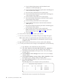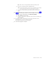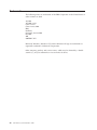
1
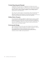
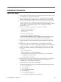
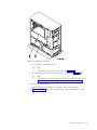
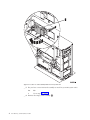
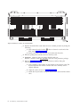
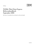
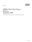
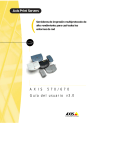
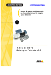
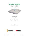
iSeries 270 and 820
30xx Memory
Card Installation
Version 5
SENG-3002-01
iSeries 270 and 820
30xx Memory
Card Installation
Version 5
SENG-3002-01
Note
Before using this information and the product it supports, be sure to read the “Safety and
Environmental Notices” on page iii and the “Notices” on page 19.
Second Edition (May 2001)
This edition applies only to reduced instructions set computer (RISC) systems.
© Copyright International Business Machines Corporation 2000, 2001. All rights reserved.
US Government Users Restricted Rights – Use, duplication or disclosure restricted by GSA ADP Schedule Contract
with IBM Corp.
Safety and Environmental Notices
Danger Notices
A danger notice calls attention to a situation that is potentially lethal or extremely
hazardous to people.
DANGER
To prevent a possible electrical shock during an electrical storm, do not
connect or disconnect cables or station protectors for communications lines,
display stations, printers, or telephones. (RSFTD003)
DANGER
To prevent a possible electrical shock from touching two surfaces with
different electrical grounds, use one hand, when possible, to connect or
disconnect signal cables. (RSFTD004)
DANGER
An electrical outlet that is not correctly wired could place hazardous voltage
on metal parts of the system or the products that attach to the system. It is the
customer’s responsibility to ensure that the outlet is correctly wired and
grounded to prevent an electrical shock. (RSFTD201)
DANGER
To prevent a possible electrical shock when adding or removing any devices
to or from the system, ensure that the power cords for those devices are
unplugged before the signal cables are connected or disconnected. If possible,
disconnect all power cords from the existing system before you add or
remove a device. (RSFTD203)
Caution Notices
A caution notice calls attention to a situation that is potentially hazardous to
people because of some existing condition.
CAUTION:
Telecommunications Statement: This unit contains over-voltage circuits between
the ac power outlet and the unit. These circuits meet the standard limits
described in International Electrical Commission (IEC) 664, installation category
II. It is the customer’s responsibility to ensure that the power outlet meets the
standards of IEC 664, installation category II. (RSFTC214)
Laser Safety Information
CAUTION:
This product may contain a CD-ROM which is a class 1 laser product.
(RSFTC240)
© Copyright IBM Corp. 2000, 2001
iii
Product Recycling and Disposal
Components of the system, such as structural parts and circuit cards, can be
recycled where recycling facilities exist. IBM does not currently collect and recycle
used IBM products from customers in the United States other than those products
that are involved in trade-in programs. Companies are available to disassemble,
reutilize, recycle, or dispose of electronic products. Contact an IBM account
representative for more information.
The system unit contains batteries and circuit boards with lead solder. Before you
dispose of this unit, these batteries and circuit boards must be removed and
discarded according to local regulations or recycled where facilities exist. This book
contains specific information on each battery type where applicable.
Battery Return Program
In the United States, IBM has established a collection process for reuse, recycling,
or proper disposal of used IBM batteries and battery packs. For information on
proper disposal of the batteries in this unit, please contact IBM at 1-800-426-4333.
Please have the IBM part number that is listed on the battery available when you
make your call. For information on battery disposal outside the United States,
contact your local waste disposal facility.
Environmental Design
The environmental efforts that have gone into the design of the system signify
IBM’s commitment to improve the quality of its products and processes. Some of
these accomplishments include the elimination of the use of Class I
ozone-depleting chemicals in the manufacturing process, reductions in
manufacturing wastes, and increased product energy efficiency. For more
information, contact an IBM account representative.
iv
30xx Memory Card Installation V5R1
Installation Instructions
Before you begin
__ 1. Take a minute to become familiar with these instructions. Note that you may
not complete every step in this instruction.
__ 2. These instructions contain steps on how to install memory (main storage
cards), including adding another 2884 card assembly, into the system unit.
__ 3. This feature is customer installed. The installation of this feature is intended for
an experienced user who understands industry terminology and who has some
system experience. If you elect not to perform this feature installation yourself,
contact IBM® or an Authorized Dealer. They can perform the feature
installation for a fee.
__ 4. When you use these instructions, you will do the following:
v Remove the system unit covers.
v Install your new hardware.
v Install covers.
v IPL your operating system.
v Verify your new hardware configuration.
You need to allow additional time to complete your jobs, back up your
system, IPL your system, and verify your hardware configuration.
__ 5. Some of the pictures in these instructions may not look exactly like the
system unit that you have. However, the steps to perform the task are the
same.
__ 6. Ensure that you have a current backup of your operating system and
licensed programs. If you have backed up the operating system and licensed
programs since the last time you applied PTFs, that backup is acceptable.
__ 7. If there are incorrect, missing or visibly damaged parts, contact one of the
following:
v Your authorized dealer
v Point of purchase (for example, IBM Direct)
v IBM Rochester Manufacturing Automated Information Line (R-MAIL)
– 1-800-300-8751 (United States)
– 1-507-253-5242 (worldwide)
__ 8. Determine if there are any existing PTF prerequisites before you install your
new feature. Go to this Web site and locate your feature number and
OS/400® release and check the prerequisites:
http://as400service.ibm.com/s_dir/slkbase.NSF/
Then do the following to get to the Customer Install Features Prerequisites:
a. Select All Documents
b. Select Collapse
c. Select General Information
d. Select Offerings
e. Select Feature Prerequisites
f. Select Customer Install Features Prerequisites
© Copyright IBM Corp. 2000, 2001
1
__ 9. If you encounter difficulties during the installation, contact your authorized
dealer or service provider.
Powering off the system unit
__ 1. Set the System performance adjustment to a value other than option 0.
__ a. On an iSeries command line, type WRKSYSVAL (QPFRADJ) and press
Enter.
__ b. Select the Change option on the Work with System Values display and
press Enter.
__ c. If you have a Performance adjustment value of option 1, option 2, or
option 3 you do not need to change the value. Press Enter.
If the Performance adjustment value is 0 (No adjustment), it is
necessary to change the value to 2.
__ d. Press F3 once to return to the Main Menu.
__ 2. Ensure that all jobs are complete (WRKACTJOB).
__ 3. When all jobs are complete, type: pwrdwnsys *immed on an iSeries command
line and press the Enter key.
Note: If you encounter difficulties during the installation, contact your
dealer or your service provider.
__ 4. When the iSeries is completely powered down disconnect all PCs from the
system unit. Power off all devices, such as printers and displays, that are
connected to the system unit.
__ 5. Unplug any power cords, such as printers and displays, from electrical
outlets.
__ 6. Unplug the system unit power cord from the electrical outlet.
__ 7. Remove the unit back and side cover. Refer to “Unit Covers” on page 15.
__ 8. Attach the disposable wrist strap to prevent electrostatic discharge from
damaging a device. Attach the adhesive part of the foil to an unpainted
surface.
Notes:
a. Follow the same precautions you would use without the wrist strap. The
2209 Disposable Wrist Strap is for static control. It will not increase nor
decrease your risk of receiving electric shock when using or working on
electrical equipment.
b. Discard the wrist strap immediately and contact your dealer for a
replacement, if the disposable wrist strap appears damaged or is cut off.
Do not continue until a new wrist strap is available.
c. Remove the liner from the copper foil at the end, when you unroll the
strap.
d. Attach the copper foil to an exposed, unpainted metal surface on the
frame of the unit (electrical ground).
Identifying the memory location
Depending on which system processor you have, memory can be located on the
inside of your system unit or in a separate card assembly (feature 2884).
2
30xx Memory Card Installation V5R1
Figure 1. Location of Access Cover
__ 1. Do you have a 270 system unit?
Yes
No
↓
You have a 820 system unit. Go to step 5 on page 4.
__ 2. Does your system unit have an access cover as shown in Figure 1 A?
Yes
No
↓
The memory is located on the inside of your 270 system unit. Go to
“Installing memory cards inside your system unit” on page 7.
__ 3. Remove the access cover.
Note: A customer can safely use all latches that are colored blue.
__ 4. Figure 2 on page 4 shows the location of the 2884 card assembly in a 270
system unit.
Installation Instructions
3
Figure 2. Location of card assembly 2884 in a 270 system unit
__ 5. Do you have a new 2884 card assembly to install in your 820 system unit?
Yes
No
↓
Go to step 7 on page 5.
__ 6. Remove the empty card assembly C .
4
30xx Memory Card Installation V5R1
Figure 3. Location of Card Assembly 2884 in 820 Unit
__ 7. Remove the 2884 card assembly B or C from the system unit by doing
the following:
__ a. Unlatch the two blue latches on the 2884 until the card assembly
slightly “pops” out.
__ b. Pull on both latches at the same time to remove the card assembly
from the system unit.
__ c. Turn the card assembly over and lay it on the static protective bag
provided.
Adding memory to the card assembly
__ 1. Before you remove the blank filler cards and install the memory into the
card assembly, read the following:
v Figure 4 on page 6 shows memory card locations on the main storage card
assembly.
v Fill positions C and D before installing memory cards in positions E, F, G,
and H.
v Install memory in sets of four. For example, you cannot fill only positions
E and G and later fill positions F and H. You must install all four memory
cards at one time.
v Pairs of memory cards must be either 128MB, 256MB, or 512MB. Pairs
installed in E and G must match pairs installed in F and H.
v Go to step 2 on page 6.
Installation Instructions
5
Figure 4. Memory Locations on Card Assembly
__ 2. Remove the blank filler cards from the next available positions by doing the
following:
__ a. Push outward on the latches A that are located at each end of the
filler card, Figure 5 on page 7.
__ b. Remove the filler card from the card socket and discard it.
__ 3. Find the package that contains the new memory cards.
__ 4. Attention: Memory cards are fragile. Handle with care.
Remove a memory card, one at a time, from the static protective package.
__ 5. Refer to Figure 5 on page 7 to install the memory card by doing the
following:
__ a. Look carefully at the notches on the bottom of the memory card. The
distance between the notches and the end of the memory card is
slightly different.
__ b. Align the card as shown in Figure 5 on page 7.
__ c. Match the keyed notches and push down on the card until the latches
close.
6
30xx Memory Card Installation V5R1
Figure 5. Install Memory Cards
__ 6. Install the remaining memory cards.
__ 7. When you finish installing all the memory cards, turn the card assembly
over, and slide it into the system unit. Push on both card latches at the same
time. Close the latches when you cannot push the card assembly any further
into the system unit.
__ 8. Reinstall the access cover.
__ 9. You have completed the installation of the memory cards in your system.
Go to “Installing system unit covers” on page 10.
Installing memory cards inside your system unit
__ 1. Figure 6 on page 8 and Figure 7 on page 9 show the memory card
connectors on the processor A inside your system unit.
Installation Instructions
7
Figure 6. Memory Connectors View 1
8
30xx Memory Card Installation V5R1
Figure 7. Memory Connectors View 2
__ 2. Refer to the figure that matches your system unit to place the memory in
the correct order.
__ 3. Place memory cards as follows on the processor:
v In pairs, beginning with C and D, then E and F, and so on.
v Each pair of storage cards must be either 128MB, 256MB, or 512MB.
__ 4. Remove the blank filler cards from the next available positions by doing the
following:
__ a. Push outward on the latches that are located at each end of the filler
card, Figure 6 on page 8.
__ b. Remove the filler card from the card socket and discard it.
__ 5. Find the package that contains the new memory cards.
__ 6. Attention: memory cards are fragile. Handle with care.
Remove a memory card, one at a time, from the static protective package.
__ 7. Install the memory card in the next available position (Figure 6 on page 8)
beginning with C and D by doing the following:
__ a. Look carefully at the notches on the bottom of the memory card. The
distance between the notches and the end of the card is slightly
different.
__ b. Align the card as shown in Figure 6 on page 8.
__ c. Match the keyed notches and push forward on the card until the
latches close.
Installation Instructions
9
__ 8. Install the second memory card.
__ 9. Do you have any other adapter cards or devices to install?
No
Yes
↓
If you have another device such as an adapter card, a tape unit, or
disk units to install, go to the instructions that came with that
device.
Go to “Installing system unit covers”.
Installing system unit covers
__ 1. Remove the wrist strap.
__ 2. Figure 8 shows how to install the system unit side cover by aligning the tabs
on the top and bottom edge. Press forward to make sure that all tabs enter
the slots. Slide the cover toward the front of the system unit until it stops
and install the screws.
Figure 8. Install system unit side cover
__ 3. Install the system unit back cover.
10
30xx Memory Card Installation V5R1
__ 4. DANGER
An electrical outlet that is not correctly wired could place hazardous
voltage on metal parts of the system or the products that attach to the
system. It is the customer’s responsibility to ensure that the outlet is
correctly wired and grounded to prevent an electrical shock.
(RSFTD201)
Plug the following power cords into an electrical outlet.
v System unit
Note: Do not power on your system unit at this time.
v System unit console
__ 5. Plug in and power on all attached devices, such as printers and displays.
Completing the installation
__ 1. Is your system unit an iSeries 270 or 820?
270
820
↓
Go to step 4.
__ 2. Look at the Function/Data display on the control panel. Refer to “System
unit control panel” on page 17.
__ 3. Does 01 B N V=S appear in the Function/Data display?
Yes
No
↓
Do the following:
__ a. Press the Increment/Decrement push button until 02 appears
in the Function/Data display.
__ b. Press the Enter push button on the control panel.
__ c. Press the Increment/Decrement push button until B appears
in the Function/Data display.
__ d. Press the Enter push button on the control panel.
__ e. Press the Increment/Decrement push button until N appears
in the Function/Data display.
__ f. Press the Enter push button on the control panel.
__ g. Press the Increment/Decrement push button until S appears
in the Function/Data display.
__ h. Press the Enter push button on the control panel.
__ i. Press the Increment/Decrement push button until 01 appears
in the Function/Data display.
__ j. Press the Enter push button on the control panel.
01 B N S should appear in the Function/Data display. If it
does not, repeat steps 3a through 3i.
__ k. Go to step 6 on page 12.
__ 4. Look at the Function/Data display on the control panel.
__ 5. Does 01 B V=S appear in the Function/Data display?
Yes
No
↓
Do the following:
Installation Instructions
11
__ a. Press the Mode Select button until the Manual mode
indicator (a small hand) lights up.
__ b. Press the Increment/Decrement push button until 02 appears
in the Function/Data display.
__ c. Press the Enter push button on the control panel.
__ d. Press the Increment/Decrement push button until B appears
in the Function/Data display.
__ e. Press the Enter push button on the control panel.
__ f. Press the Increment/Decrement push button until S appears
in the Function/Data display.
__ g. Press the Enter push button on the control panel.
__ h. Press the Mode Select button until the Normal indicator
(OK) lights up.
__ i. Press the Increment/Decrement push button until 01 appears
in the Function/Data display.
__ j. Press the Enter push button on the control panel.
01 B S should appear in the Function/Display panel. If it
does not appear, repeat steps 5a through 5i.
__ k. Go to step 6.
__ 6. Power on the workstation or PC that is your console.
__ 7. Press the system unit power-on button. The power-on light will appear.
Note: There will be an approximately 10 second delay before power on.
The system takes approximately 5 to 20 minutes to power on and
complete an IPL.
__ 8. Sign on the system unit. Ensure that you have service tools authority.
__ 9. To verify your memory (main storage) card configuration, do the following
.
__ a. Type strsst on the command line and press Enter.
__ b. Type your service tools userid and service tools password on
the System Service Tools (SST) Sign On display and press Enter.
__ c. Select Start a service tool on the System Service Tools (SST) display
and press Enter.
__ d. Select Hardware service manager on the Start a Service Tool display
and press Enter.
__ e. Select Logical hardware resources (Buses, IOPs, Controllers...) from
the Hardware Service Manager display and press Enter.
__ f. Select Main Storage Resources on the Logical Hardware Resources
display and press Enter.
The following screen is an example of what you should see.
Display Main Storage Information
Opt Location
-
1
2
3
Type
Size
Resource Name
32
32
32
MS0x
MS0x
MS0x
Status
Operational
Operational
Operational
Verify that the status is Operational for all locations.
12
30xx Memory Card Installation V5R1
Note: If the status is not Operational, check the memory cards.
__ g. If you have a printer, print the configuration list.
Note: To print the hardware resources list, press F12 one time. When
the Logical Hardware Resources menu appears, press F6.
__ h. To return to the Main Menu, press F3 three times and then press
Enter.
__ 10. If you changed the System performance adjustment option value in step 1 on
page 2, do the following to return to what you had prior to your upgrade:
__ a. On an iSeries command line, type WRKSYSVAL (QPFRADJ).
__ b. Select Change and press Enter.
__ c. Change the Performance adjustment value to what it was before you
did the upgrade.
__ 11. For additional iSeries information, go to the iSeries Information Center,
SK3T-4091-00 CD or from the following Web site:
http://www.ibm.com/eserver/iseries/infocenter
__ 12. Your feature upgrade is complete.
Installation Instructions
13
14
30xx Memory Card Installation V5R1
Unit Covers
Locate the diagram of the unit you are working on. If you have a 270 system unit
in a rack, go to “270 unit in a rack” on page 16.
270 and 820 System Units
To access the PCI card location, you need to remove the back cover and the side
cover:
__ 1. Place your hand near the bottom of the back cover and lift up and out.
__ 2. Attention: If removing side cover while powered on, errors may occur due
to electromagnetic interference.
Remove the right side cover (view from back) by loosening the thumbscrews
and sliding the cover from front to back until it stops.
__ 3. Pull the cover out.
© Copyright IBM Corp. 2000, 2001
15
270 unit in a rack
1. Press latches B and pull the server out using the handle C.
2. Refer to previous unit diagram to remove the side cover.
16
30xx Memory Card Installation V5R1
System unit control panel
Go to the front of your system unit. Open the control panel door.
Your control panel looks like either Figure 9 or Figure 10 on page 18. Refer to the
control panel for your unit.
Figure 9. Control panel without Electronic Keystick
A
Power On Light
v A blinking light indicates power to the unit.
v A constant light indicates that the unit is up and working.
B
Power Push button
C
Processor Activity
D
System Attention
E
Function/Data Display
F
Increment/Decrement buttons
G
Enter Push button
H
Auto
J
Normal
K
Manual
.
.
.
.
.
.
.
© Copyright IBM Corp. 2000, 2001
17
If your control panel looks like this, before you can use F Increment/Decrement
buttons and G Enter push button, you need to press H Mode Selects to select
Manual mode N.
Figure 10. Control panel with Electronic Keystick
18
A
Power On Light
v A blinking light indicates power to the unit.
v A constant light indicates that the unit is up and working.
B
Power Push button
C
Processor Activity
D
System Attention
E
Function/Data Display
F
Increment/Decrement buttons
G
Enter Push button
H
Mode Selects
J
Electronic Keystick Slot
K
Secure
L
Auto
M
Normal
N
Manual
30xx Memory Card Installation V5R1
Notices
This information was developed for products and services offered in the U.S.A.
IBM may not offer the products, services, or features discussed in this document in
other countries. Consult your local IBM representative for information on the
products and services currently available in your area. Any reference to an IBM
product, program, or service is not intended to state or imply that only that IBM
product, program, or service may be used. Any functionally equivalent product,
program, or service that does not infringe any IBM intellectual property right may
be used instead. However, it is the user’s responsibility to evaluate and verify the
operation of any non-IBM product, program, or service.
IBM may have patents or pending patent applications covering subject matter
described in this document. The furnishing of this document does not give you
any license to these patents. You can send license inquiries, in writing, to:
IBM Director of Licensing
IBM Corporation
500 Columbus Avenue
Thornwood, NY 10594
U.S.A.
The following paragraph does not apply to the United Kingdom or any other
country where such provisions are inconsistent with local law:
INTERNATIONAL BUSINESS MACHINES CORPORATION PROVIDES THIS
PUBLICATION “AS IS” WITHOUT WARRANTY OF ANY KIND, EITHER
EXPRESS OR IMPLIED, INCLUDING, BUT NOT LIMITED TO, THE IMPLIED
WARRANTIES OF NON-INFRINGEMENT, MERCHANTABILITY OR FITNESS
FOR A PARTICULAR PURPOSE. Some states do not allow disclaimer of express or
implied warranties in certain transactions, therefore, this statement may not apply
to you.
This information could include technical inaccuracies or typographical errors.
Changes are periodically made to the information herein; these changes will be
incorporated in new editions of the publication. IBM may make improvements
and/or changes in the product(s) and/or the program(s) described in this
publication at any time without notice.
Information concerning non-IBM products was obtained from the suppliers of
those products, their published announcements or other publicly available sources.
IBM has not tested those products and cannot confirm the accuracy of
performance, compatibility or any other claims related to non-IBM products.
Questions on the capabilities of non-IBM products should be addressed to the
suppliers of those products.
If you are viewing this information softcopy, the photographs and color
illustrations may not appear.
The drawings and specifications contained herein shall not be reproduced in whole
or in part without the written permission of IBM.
IBM has prepared this publication for use by customer personnel for operating and
planning for the specific machines indicated. IBM makes no representations that it
is suitable for any other purpose.
© Copyright IBM Corp. 2000, 2001
19
Trademarks
The following terms are trademarks of the IBM Corporation in the United States or
other countries or both:
AS/400
AS/400e series
Client Access
Client Access/400
IBM
NetFinity
Operating System/400
OS/400
400
800-IBM-CALL
Microsoft, Windows, Windows NT, and the Windows 95 logo are trademarks or
registered trademarks of Microsoft Corporation.
Other company, product, and service names, which may be denoted by a double
asterisk (**), may be trademarks or service marks of others.
20
30xx Memory Card Installation V5R1
Readers’ Comments — We’d Like to Hear from You
iSeries 270 and 820
30xx Memory
Card Installation
Version 5
Publication No. SENG-3002-01
Overall, how satisfied are you with the information in this book?
Overall satisfaction
Very Satisfied
Satisfied
Neutral
Dissatisfied
h
h
h
h
Very
Dissatisfied
h
How satisfied are you that the information in this book is:
Accurate
Complete
Easy to find
Easy to understand
Well organized
Applicable to your tasks
Very Satisfied
Satisfied
Neutral
Dissatisfied
h
h
h
h
h
h
h
h
h
h
h
h
h
h
h
h
h
h
h
h
h
h
h
h
Very
Dissatisfied
h
h
h
h
h
h
Please tell us how we can improve this book:
Thank you for your responses. May we contact you?
h Yes
h No
When you send comments to IBM, you grant IBM a nonexclusive right to use or distribute your comments in any
way it believes appropriate without incurring any obligation to you.
Name
Company or Organization
Phone No.
Address
SENG-3002-01
___________________________________________________________________________________________________
Readers’ Comments — We’d Like to Hear from You
Cut or Fold
Along Line
_ _ _ _ _ _ _Fold
_ _ _and
_ _ _Tape
_ _ _ _ _ _ _ _ _ _ _ _ _ _ _ _ _ _ _ _ _ _ _ _ _ _ _Please
_ _ _ _ _do
_ _not
_ _ staple
_ _ _ _ _ _ _ _ _ _ _ _ _ _ _ _ _ _ _ _ _ _ _ _ _ _ _ _ _Fold
_ _ _and
_ _ Tape
______
NO POSTAGE
NECESSARY
IF MAILED IN THE
UNITED STATES
BUSINESS REPLY MAIL
FIRST-CLASS MAIL PERMIT NO. 40 ARMONK, NEW YORK
POSTAGE WILL BE PAID BY ADDRESSEE
IBM CORPORATION
ATTN DEPT 542
IDCLERK
3605 Highway 52 N
ROCHESTER MN 55901-7829
_________________________________________________________________________________________
Fold and Tape
Please do not staple
Fold and Tape
SENG-3002-01
Cut or Fold
Along Line
Printed in the United States of America
on recycled paper containing 10%
recovered post-consumer fiber.
SENG-3002-01