1
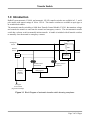
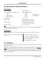
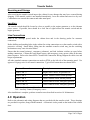
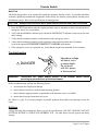
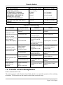
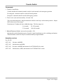
Hubbell Industrial Controls, Inc. A subsidiary of Hubbell Incorporated 4301 Cheyenne Drive Archdale, NC Telephone (336) 434-2800 FAX (336) 434-2803 Instruction Manual Transfer switches LX-440 Non-Automatic LX-450 Automatic 100, 200, 260, 400, 600, 800, 1000, 1250 Ampere 2, 3, 4 Pole Publication No. 201 April, 2001 Transfer Switch Table of Contents 1.0 Introduction....................................................................................................................................3 2.0 Specifications and Certifications ..................................................................................................4 Specifications .....................................................................................................................................4 Certifications ......................................................................................................................................4 3.0 Installation......................................................................................................................................4 Receiving and Storage ........................................................................................................................5 Location ..............................................................................................................................................5 Line Connections................................................................................................................................5 4.0 Operation ........................................................................................................................................5 Automatic Operation ..........................................................................................................................6 5.0 Standard and Optional Features ..................................................................................................7 Standard Features ...............................................................................................................................7 Optional Features................................................................................................................................8 6.0 Maintenance .................................................................................................................................10 Transfer Test.....................................................................................................................................10 Troubleshooting................................................................................................................................11 Settings .............................................................................................................................................11 7.0 Transfer Control Relay Board....................................................................................................12 8.0 Plant Exerciser Timer .................................................................................................................14 Set the time .......................................................................................................................................14 Programming ....................................................................................................................................14 9.0 Spare Parts and Drawing References ........................................................................................16 Spare Parts ........................................................................................................................................16 Drawing References .........................................................................................................................16 Page 2 of 16 Pages Transfer Switch 1.0 Introduction Hubbell’s non-automatic, LX-440, and automatic, LX-450, transfer switches are available in 2, 3, and 4 pole models with ampere ratings of 100 to 1250 A. The transfer switches are available as open type or in an individual cabinet. The automatic transfer switch has a Solid State Transfer Control Module, LX-301, that monitors voltage and controls the transfer to and from the normal and emergency sources. The non-automatic transfer switch has a selector switch to manually initiate transfer. A handle is included with all transfer switches to manually close the normal or emergency contacts. TSE Emergency Source TSN Normal Source To load PRM optional Switching Mechanism Normal Source Transformer Control Module (LX-301) Emergency Source Transformer Transfer Control Relay Board To engine start contacts (If generator backup) Figure 1-1 Block Diagram of automatic transfer switch showing one phase Page 3 of 16 Pages Transfer Switch 2.0 Specifications and Certifications Specifications Switch Mechanism Solenoid Actuation Short Circuit Ratings of Transfer Switches 100 A 200 A 260, 400, 600 A 800, 1000, 1250 A RMS Symmetrical Amperes 42,000 50,000 When protected by 65,000 a circuit breaker. 85,000 Control Voltage 120 VAC Pick-up Voltage 90% of normal source voltage 90% of emergency source voltage Drop-out Voltage 84% of normal source voltage 84% of emergency source voltage Auxiliary Contacts 10 A, 125/250 VAC Note Time delay settings and voltage pick-up and drop-out levels are set at the factory and should not be changed without consulting the factory. Certifications Hubbell’s Automatic transfer switches meet the requirements for all of the certifications listed below. UL 1008 Standard for Safety for automatic transfer NEC Article 517, Health Care facilities switches NEC Article 702, Optional Standby Systems NEC Article 701, Legally Required Standby Systems (LX-450 only) NFPA 20 Installation of Fire Pumps 3.0 Installation Refer to the transfer switch nameplate to ensure that the voltage, current, and horsepower ratings are compatible with the load. Refer to the receiving, handling, storage, installation, and inspection procedures in the Instruction Manual that accompanies the combination Fire Pump Controller and automatic transfer switch. Many of the procedures in the installation section are applicable to the automatic transfer switch in the adjoining cabinet. For automatic transfer switches sold as an individual unit, and for additional information, follow the procedures below. Page 4 of 16 Pages Transfer Switch Receiving and Storage After receiving the transfer switch inspect the cabinet for any damage that may have occurred during shipping. If the transfer switch is not installed immediately, cover the cabinet and store in a dry area. Condensation can corrode the contacts and other metal parts. Location The transfer switch should be located as close as possible to the engine generator or to the alternate power source. If possible, there should be a clear line of sight between the transfer switch and the engine generator. Line Connections Refer to the drawings posted inside the cabinet door and in the drawing packet for customer connections. Before drilling and punching holes in the cabinet for wiring connections cover the transfer switch with a protective covering. Small debris falling into the automatic transfer switch may jam the switching mechanism or may cause electrical failure. Ensure that the normal (primary), emergency (alternate), and load isolation switches are open before making connections. Connect the load, normal source, and emergency source power cables in the same phase sequence. Refer to the latest NFPA 70 and Field Connections Wiring Diagram for cable sizes and torque requirements. All other standard customer connections are made to PTB1 on the left side of the mounting panel. Use approved 14-gauge wire for all control connections. Typical field connections are shown below. Terminal Connections Description PTB1-1 and –2 Engine Start Contact, for generator set PTB1-5 and -6 TSNa4 contacts closed, normal position PTB1-7 and -8 TSNa3 contacts closed, normal position PTB1-9 and -10 TSEa4 contacts closed, emergency position PTB1-11 and -12 TSEa3 contacts closed, emergency position TSN - Auxiliary Contact, Normal source TSE - Auxiliary Contact, Emergency source After installation is complete, perform a transfer test as described in section 6.0 Maintenance. 4.0 Operation Refer to the schematic and wiring diagrams that are provided with the transfer switch. These drawings are provided in a packet, along with this manual. A schematic is also posted on the inside of the cabinet door. Page 5 of 16 Pages Transfer Switch The Hubbell Transfer Control Module, LX-301, controls transfer to the emergency source and retransfer to the normal source. The LX-440 non-automatic transfer switch does not come with a Control Module. A selector switch initiates transfer and retransfer. Automatic Operation Transfer to Emergency Source The Control Module monitors the normal source phase voltage for acceptable limits of drop-out and pick-up. A NORMAL OVERRIDE ON MOMENTARY OUTAGE time delay is provided to override voltage dips causing nuisance starting of the engine generator set. If the normal source voltage is restored above the pick-up setting within the time delay period, the delay timer is reset. If the NORMAL OVERRIDE ON MOMENTARY OUTAGE time delay expires before the normal source voltage is restored, the normal source electronic control initiates engine starting of the generator set and/or activates the emergency source electronic control. The engine control relay is a 12 VDC latching relay on the Control Module. The customer connections for the engine start contacts are on PTB1 located on the left side of the transfer switch mounting panel. Refer to the Field Connections Wiring Diagram posted on the inside of the cabinet door and in the drawing packet for customer connections. The emergency source electronic control monitors the emergency source for the acceptable voltage and frequency pick-up levels. When both the voltage and frequency of the emergency source are verified, 24 VDC from the Control Module energizes the TCR (Transfer Control Relay). The normally open contacts of the TCR close to power the transfer switch switching mechanism via emergency transformer XFMR2. After the emergency source contacts close, auxiliary contacts TSEb1 open to disconnect power to the switching mechanism. Transfer switches with the NEUTRAL POSITION TIME DELAY, stop in the neutral position. After the adjustable time delay expires, Q1 on the TCR board turns on to energize the TR relay. The TR relay contacts close to re-connect power to the switching mechanism to complete the transfer. An EMERGENCY OVERRIDE ON MOMENTARY OUTAGE time delay is provided to override momentary voltage dips preventing the transfer switch from retransferring to the normal source. If the emergency source voltage is restored above the pick-up setting within the delay period, the delay timer is reset. Retransfer to Normal Source When the Control Module detects that the normal source voltage rises above the pick-up settings, the timing sequence starts for retransfer to the normal source. The RETRANSFER TO THE NORMAL time delay starts to allow the normal source to stabilize before retransfer. If the normal source does not meet pick-up requirements, the delay timer is reset. At the end of this delay, the TCR is de-energized. The normally closed contacts of the TCR close. The switching mechanism is then powered by 120 V from the normal transformer, XFMR1, through the TCR relay contacts. After the normal source contacts close , auxiliary contact TSNb1 opens to disconnect power to the switching mechanism. Transfer switches with the NEUTRAL POSITION TIME DELAY, stop in the neutral position. After the adjustable time delay expires, the TR contacts close to complete transfer. Page 6 of 16 Pages Transfer Switch 5.0 Standard and Optional Features Standard Features The following standard features are provided with the LX-450 automatic transfer switch. Indicating lights NORMAL (PL1, Green) When the transfer switch is in the normal position (normal source contacts closed) auxiliary contact TSN-1NO closes to power the pilot light. EMERGENCY (PL2, Red) When the transfer switch is in the emergency position (emergency source contacts closed) auxiliary contact TSE-1NO closes to power the pilot light. Control Module LED Indicators EMERGENCY FREQUENCY MONITOR LED (Green) This LED is on when the emergency source frequency is within the operating range. EMERGENCY VOLTAGE MONITOR LED (Red) This LED is on when the emergency source voltage is above the pick-up level. ENGINE RUNNING UNLOADED LED (Red) This LED is on when the engine generator is running during the cool down interval. NORMAL VOLTAGE MONITOR LED (Green) This LED is on when the normal source voltage is above the pick-up level. RETRANSFER TO NORMAL SOURCE LED (Red) This LED is on during the RETRANSFER TO NORMAL time delay after the normal source voltage rises above the pick-up level. TRANSFER TO EMERGENCY SOURCE LED (Red) This LED is on during the TRANSFER TO EMERGENCY time delay after the emergency source voltage and frequency is above the pick-up level. Time Delays This time delay is provided to allow the engine generator to run for a cool down period after retransfer to the normal source. At the end of this period, the engine control relay contacts activate to shutdown the engine generator. ENGINE RUNNING UNLOADED TIME DELAY This time delay overrides a retransfer to the normal source when the emergency source voltage is low or drops out momentarily. OVERRIDE MOMENTARY OUTAGES ON EMERGENCY SOURCE OVERRIDE MOMENTARY OUTAGES ON NORMAL SOURCE This time delay overrides transfer when the normal source voltage is low or drops out momentarily. RETRANSFER TO NORMAL This time delay allows the normal source to stabilize before retransfer. TRANSFER TO EMERGENCY This time delay allows the emergency source to stabilize before retransfer. Page 7 of 16 Pages Transfer Switch Auxiliary Contacts Auxiliary contacts TSNa3, -a4 and TSEa3, -a4 are available for remote alarms, pilot lights, or other applications. These contacts are pre-wired for customer connections to PTB1-7 through PTB1-12. The contacts are rated at 10 A, 125/250 VAC. Manual Disconnect Switch The MDS (Manual Disconnect Switch) is mounted on the TRC board. This switch isolates the power source to the switching mechanism. Then the automatic transfer switch can only be operated manually with the handle. CAUTION: Disconnect normal and emergency power sources before using handle to transfer the contacts. TEST push button The TEST push button simulates a loss of power from the normal source and causes the Control Module to initiate transfer to the emergency source. Optional Features The items described in this section are a few of the optional features available with the LX-450 automatic transfer switch. Contact the local Hubbell representative for additional options desired for an application. Refer to the job schematic and wiring diagrams for these and other features. BYPASS/RETRANSFER TO NORMAL push button (S1) This option is standard for combination Fire Pump Controller with automatic transfer switch to meet NFPA 20 specifications. Pressing this button allows the transfer switch to retransfer to the normal position bypassing the RETRANSFER TO NORMAL SOURCE time delay. Phase Rotation Monitor (H1) The PRM (Phase Rotation Monitor) contacts open if the phase rotation of the normal power source is not correct. If the proper phase sequence is not sensed, the LX-301 Control Module does not output a signal to the TCR board to retransfer the transfer switch to the normal source. Auxiliary Contacts (A1–A4) One additional NO/NC set of contacts may be added to the normal and the emergency source side of the transfer switch. The contacts are rated for pilot duty: 10 A at 125 or 250 VAC. BYPASS/TRANSFER TO EMERGENCY push button (S2) This push button overrides the time delay to transfer to the emergency source. Page 8 of 16 Pages Transfer Switch Plant Exerciser (B1–B2) The Plant Exerciser option is a seven-day clock that provides for automatic test operation of the generator set at pre-selected intervals. The clock is powered by a fused circuit from control transformer XFMR3. The Plant Exerciser option is used in conjunction with contacts to initiate engine starting without a load transfer, option B1. Option B2 includes a selector switch to simulate a power failure with or without a load transfer. Refer to section 8, pages 14-15, for instructions to program the Plant Exerciser timer. Remote Test (R7) This option provides terminal points for the connection of remote devices that are normally closed and wired in series with the TEST push button. An open circuit simulates failure of the normal source and initiates transfer to the emergency source. Selector Switch (R2–R4) Selector switches are available to set the transfer switch for testing, automatic or manual mode, and to test start the engine for troubleshooting and maintenance. Selector switches with an OFF position, option R2, include an OFF indicating light (PL4, white). Switches with a TEST position initiate a load transfer. NEUTRAL POSITION TIME DELAY (N) When the normal source contacts open, the NEUTRAL POSITION TIME DELAY starts. The timer circuit on the TCR board, temporarily disconnects the power source to the switching mechanism while the automatic transfer switch is in the neutral position (normal and emergency source contacts open). The adjustable timer is usually set for three seconds. The red START DELAY LED indicates the timer is counting. After the delay, the green END DELAY indicates the TR (timer relay) is energized to reconnect power to the switching mechanism. Page 9 of 16 Pages Transfer Switch 6.0 Maintenance DANGER: Do not touch the transfer switch until ALL power is disconnected. Shocks, burns, or death may result from high voltage. CAUTION: Only personnel who are familiar with the power distribution system and this manual should be allowed to inspect or perform maintenance on the transfer switch. Preventive maintenance The following checks should be preformed as part of routine maintenance: • A transfer test of the transfer switch should be preformed every week. • The transfer switch should be kept clean of dust and moisture. DO NOT USE A BLOWER TO CLEAN the switch or the inside of the enclosure. Always use a clean cloth or vacuum to prevent debris from lodging in the switching mechanism. • Check all wiring connections. • Visually inspect the contacts for surface deposits and pitting. This inspection should be preformed annually. Transfer Test After installation, and each week thereafter, check the operation of the transfer switch by performing a manual and an automatic transfer. Manual Test WARNING: Disconnect the emergency and normal power sources before transferring with the handle. Manual operation is only for testing the mechanical operating mechanism or switching when there is a control problem. Manual operation of the transfer switch is performed by sliding the square notch at the end of the handle onto the end of the square bar on the left side of the switch. Push the handle up to transfer to the normal source (A). To transfer the switch to the emergency source (B) insert a screw driver in the TRIP hole to put the switch in the neutral position. Then push the handle up and insert a screw driver into the SELECT hole to transfer the switch to the emergency source. CAUTION: Do not leave the handle on the square bar. The handle prevents closure of the cabinet door and may cause damage to or prevent emergency operation of the transfer switch. Page 10 of 16 Pages Transfer Switch Auto Test The following procedure is an example for testing the automatic transfer switch. A procedure should be written by qualified personnel that is applicable to the facility, the transfer switch options, and the power distribution system. Refer to job specifications for timing delays. CAUTION: Always close enclosure door when switch transfers with power connected. 1. Press the TEST push button until the engine generator starts or automatic transfer switch transfers if emergency source is a second utility. 2. Verify that the NORMAL indicator goes off and the EMERGENCY indicator comes on per the time delay settings. 3. Verify that the automatic transfer switch transfers to the emergency source. 4. Verify that the automatic transfer switch retransfers to the normal position after 30 minutes or press the optional BYPASS/RETRANSFER TO NORMAL push button. 5. If the emergency source is a generator set, verify that the engine runs unloaded for five minutes. Troubleshooting ! WARNING: DANGER Hazardous voltage will shock, burn, or cause death. Do not touch until ALL power is disconnected. Disconnect ALL power supply sources to the transfer switch before servicing to prevent shock or accident hazard. Before troubleshooting, perform the following checks: a. visual inspection for physical damage. b. ensure that all switches are in the normal operating position. c. ensure that the engine generator is operational or the alternate source is available. d. ensure that all wiring connections are secure. See Table 6-1, page 12, for some examples of possible problems that could occur and steps to take for repair. Settings Voltage and time delay settings are factory set per job specifications. DO NOT CHANGE VOLTAGE SETTINGS WITHOUT CONSULTING HUBBELL ICD. The table below lists the typical time delay settings. Page 11 of 16 Pages Transfer Switch Time Delay function NORMAL OVER-RIDE ON MONETARY OUTAGE RETRANSFER TO NORMAL ENGINE RUNNING UNLOADED EMERGENCY OVER-RIDE ON MOMENTARY OUTAGE TRANSFER TO EMERGENCY NEUTRAL POSITION TIME DELAY (optional) Frequency Monitor Typical factory setting Adjustment Range 1 second, engine generator 3 seconds, utility 30 minutes 5 minutes 1 second 0.5 to 6 seconds 2 seconds 3 seconds 0 seconds to 5 minutes 1 second to 10 minutes 60 Hz 30 to 100 Hz 2 to 30 minutes 2 to 30 minutes 0.5 to 6 seconds Table 6-1 Troubleshooting Condition Automatic transfer switch does not transfer LED’s on Control Module indicate proper timing sequence, voltage, and frequency Automatic transfer switch transfers when normal source OK Engine generator does not start Engine generator continues to run unloaded Possible cause Checks Action Switching mechanism jammed Isolate power sources Actuate transfer switch manually Transformer fault Check for 115 V output from transformers Replace transformer TCR board fault Inspect board for damage Check TCR and TR relays Repair/Replace TCR board Check board components with ohm meter Phase Rotation Monitor fault (ATS/Fire Pump) Check for correct phase sequence. Check PRM w/ ohm meter Correct line connections for proper phase sequence. Replace PRM Control Module Check VOLTAGE MONITOR LED’s Repair/Replace Control Module Engine Start Relay Check contacts at PTB11 and -2 Replace MB relay Control Module fault Check Engine Start Contacts Repair/Replace Control Module Engine Start Relay fault Relay circuit fault Check relay on Control Module Repair/Replace Control Module 7.0 Transfer Control Relay Board Refer to schematic 49271-500. The primary purpose of the Transfer Control Relay board is to control the operation of the switching mechanism. The board also has the isolation switch alarm circuit and relays. Page 12 of 16 Pages Transfer Switch Components 1. Transfer Control Relay Controls whether the automatic transfer switch is in the normal or the emergency position. De-energized - automatic transfer switch in Normal position Energized - automatic transfer switch in Emergency position 2. Timer circuit (not used on assembly –101 and -104) This circuit determines how long the automatic transfer switch stays in the neutral position. Jumper JMP1 selects one of four ranges. Potentiometer P1 adjusts the time within that range. The four ranges are: 1–6 seconds 20–120 seconds 5–30 seconds 100–600 seconds 3. Manual Disconnect Switch (not used on assembly -103) Opening this switch disconnects power from the control transformers to the switching mechanism. Then the transfer switch can only be switched manually using the handle. Assembly versions For LX-450 49271-101 No timer with MDS. 49271-102 Includes timer and MDS. 49271-104 No timer with MDS and monitor for AUTO/MANUAL switch. 49271-105 Includes timer, MDS, and monitor for AUTO/MANUAL switch. Page 13 of 16 Pages Transfer Switch 8.0 Plant Exerciser Timer Set the time 1) Press the Res. (reset) button to clear the memory 2) Press and hold the (time/run mode) button while setting the time a) Press the h button to set the hours b) Press the m button to set the minutes c) Repeatedly press the Day button to select the day of the week (1—7, Monday–Sunday) 3) When set correctly, the colon between the hours and minutes flashes 4) To reset for daylight savings time a) Press the ±1h button one time in the spring to advance the time one hour b) Press ±1h one time in the fall to set the time back one hour Notes The time and the day of the week must be set before programming the Timer. The Timer has sufficient back up power to maintain the time and program settings for up to four days. Programming 1) To set the Timer to transfer the transfer switch with load or no load once a week and run generator set for thirty minutes, Friday at 9:00 a.m. a) Press the Prog. (program) button to display the day of the week and time setting for the program b) Press the (ON/OFF) button once to display the ON (open circle) symbol c) Press h to set the hours until 09 AM is displayed d) Press m to set the minutes until 00 is displayed e) Press Day eight times to select 5 (Friday) as the day of the week to run (Press the button four times to select Monday or up to 10 times to select Sunday.) f) Press Prog. button g) Press twice to display the OFF (open circle with dot) symbol h) Repeat steps c), d), and e) to set 9:30 a.m., Friday i) Press Prog. button j) Press the (time/run mode) button 2) To review the programming a) Press Prog. once to see the transfer time Page 14 of 16 Pages Transfer Switch b) Press Prog. a second time to see the retransfer time. c) Press Prog. a third time to see the number of additional program times Fr18 3) To manually override the Timer press the button a) Pressing once transfers the Timer contacts—output ON (starts the engine) Automatic control resumes after the next programmed event—temporary override b) Press twice consecutively turns the output ON—permanent override c) Press three times consecutively to turn the output OFF—permanent override d) Press until the symbol appears to end the override—return to run mode 4) To delete a program a) Press Prog. to display the program to delete b) Press m until the display is blank c) Press h until the display is blank d) Press to return to run mode Page 15 of 16 Pages Transfer Switch 9.0 Spare Parts and Drawing References The following lists contain part numbers and drawing numbers for identification and for ordering. If materials are needed from Hubbell, contact the local Hubbell representative to request the desired information or parts. Spare Parts Description Part No. Transformer 100 VA 200 VA 57511355 57511343 Socket 402066520 Lens, red 402067520 Lens, green 402066720 120 V Bulb 80324905 Black Push Button 12 point terminal strip Spares 2 Years Spares 2 Years Description Part No. Phase Rotation Monitor 208–260 V 440–480 V 57418-398 57418-399 LX-450 TCR Board w/o Timer, w/ Switch w/ Timer, w/ Switch w/o Timer, w/ Switch w/ Timer, w/ Switch 49271-101 49271-102 49271-104 49271-105 1 80320400 AR relay, 2 pole 31658-123 1 57520323 AR1 relay, 3 pole 31658-112 1 Plant Exerciser, SPDT 31658139 1 1 1 2 LX-301 Control Modules Standard Standard 200 V/3 pole/60 Hz 90363-001 240 V/3 pole/60 Hz 90363-005 208 V/3 pole/60 Hz 90363-002 440 V/3 pole/60 Hz 90363-006 220 V/3 pole/60 Hz 90363-003 460 V/3 pole/60 Hz 90363-007 230 V/3 pole/60 Hz 90363-004 480 V/3 pole/60 Hz 90363-008 Engine Start Relay, 12 VDC 31658-076 1 Drawing References Drawing No. Title Drawing No. 49271-500 Title Schematic Transfer Control Relay Board Notes As built schematics and wiring diagrams are provided as part of the drawing packet supplied with each transfer switch. Refer to Bulletin 1000 for information about one year parts and labor warranty. Page 16 of 16 Pages