1
HP Apollo 9000 Model 750
Owner's Guide
for HP-UX Users
HP 9000 Series 700 Computers
ABCDE
HP Part No. A1961-90000
Printed in USA
June 1991
Edition 1
E0691
Legal Notices
The information in this document is subject to change without notice.
Hewlett-Packard makes no warranty of any kind with regard to this manual,
including, but not limited to, the implied warranties of merchantability and
tness for a particular purpose. Hewlett-Packard shall not be held liable for
errors contained herein or direct, indirect, special, incidental or consequential
damages in connection with the furnishing, performance, or use of this
material.
Warranty. A copy of the specic warranty terms applicable to your
Hewlett-Packard product and replacement parts can be obtained from your
local Sales and Service Oce.
c copyright 1983-91 Hewlett-Packard Company
This document contains information which is protected by copyright. All rights
are reserved. Reproduction, adaptation, or translation without prior written
permission is prohibited, except as allowed under the copyright laws.
Restricted Rights Legend. Use, duplication or disclosure by the U.S.
Government is subject to restrictions as set forth in subparagraph (c) (1) (ii)
of the Rights in Technical Data and Computer Software clause at DFARS
252.227-7013 for DOD agencies, and subparagraphs (c) (1) and (c) (2) of the
Commercial Computer Software Restricted Rights clause at FAR 52.227-19 for
other agencies.
HEWLETT-PACKARD COMPANY
3000 Hanover Street
Palo Alto, California 94304 U.S.A.
c copyright 1980, 84, 86 AT&T Technologies, Inc.
UNIX is a registered trademark of Unix System Laboratories Inc. in the USA
and other countries.
c copyright 1979, 80, 83, 85-90 Regents of the University of California
This software is based in part on the Fourth Berkeley Software Distribution
under license from the Regents of the University of California.
Printing History
The manual printing date and part number indicate its current edition. The
printing date will change when a new edition is printed. Minor changes may be
made at reprint without changing the printing date. The manual part number
will change when extensive changes are made.
Manual updates may be issued between editions to correct errors or document
product changes. To ensure that you receive the updated or new editions, you
should subscribe to the appropriate product support service. See your HP sales
representative for details.
June 1991 . . . Edition 1.
Safety Symbols and Conventions
The following conventions are used throughout this manual:
Note
Caution
Warning
Notes contain important information set o from the text.
Caution messages indicate procedures which, if not observed,
could result in loss of data or damage to equipment. Do not
proceed beyond a CAUTION sign until the indicated conditions
are fully understood and met.
Warning messages indicate procedures or practices which, if
not observed, could result in personal injury. Do not proceed
beyond a WARNING sign until the indicated conditions are fully
understood and met.
iv
Warnings and Cautions
Removing device cover may expose sharp edges in equipment
chassis. To avoid injury, use care when installing customer
add-on devices.
WARNUNG: Das Entfernen der Gerateabdeckung legt die scharfen Kanten
im Inneren des Gerates frei. Um Verietzungen zu vermeiden,
seien Sie vorsichtig beim Einbau von zusatzlichen Bauteilen,
die vom Kunden selber eingebaut werden konnen.
Des bords tranchants du ch^assis de l'equipement peuvent ^atre
ADVERTISSEMENT: exposes quand le cache de l'unite n'est pas en place. Pour
eviter des blessures, faire tres attention lors de l'installation de
modules supplementaires par le client.
WARNING:
To avoid personal injury and to prevent possible equipment
damage, ensure that the ac power is o and the ac power cord
is disconnected.
WARNUNG: Um Verletzungen und mogliche Ausrustungsschaden zu
verhindern, mu die Wechselstrmoquelle ausgeschaltet sein und
das Wechselstromzufuhrungskabel aus der Steckdose entfernt
sein.
ADVERPour eviter les risques de blessures et de dommages au
TISSEMENT: materiel, s'assurer que le systeme n'est pas sous tension et que
le l d'alimentation electrique c.a. est debranche.
WARNING:
v
Disconnect power plug from wall outlet or source power
before moving or removing the device, or installing add-on
components.
WARNUNG: Entfernen Sie die Stromzufuhrung von der Steckdose oder
der Stromquelle bevor Sie das Gerat bewegen, abbauen, oder
zusatzliche Bauteile installieren.
Debrancher la che de las prise de courant ou de la source
ADVERTISSEMENT: d'alimentation electrique avant de deplacer ou de retirer
l'unite, ou avant d'installer des modules supplementaires.
WARNING:
Lifting the 19-inch monitor requires more than one person
because the unit weighs more than 40 pounds (18 kilograms).
WARNUNG: Der-19-inch (48 cm) Bildschirm mu von mehreren Personen
angehoben werden, da die Einheit uber 40 Pfund (18
kilogramm) wiegt.
ADVERIl faut plus d'une personne pour soulever le moniteur de 48 cm
TISSEMENT: (19 pouces) etant donne qu'il pese plus de 18 kg.
WARNING:
Monitor input voltage must be the same as the system's input
voltage.
VORSICHT: Die Bildschirm-Eingangsspannung mu genauso gro sein wie
die Eingangsspannung des Systems.
ATTENTION: La tension d'entree du moniteur doit ^etre la m^eme que la
tension d'entree du systeme.
CAUTION:
Do not unplug the monitor video cable while the system unit is
powered on.
VORSICHT: Ziehen Sie nicht das Stromzufuhrungskabel zum Bildschirm aus
der Steckdose, solange das Gerat eingeschaltet ist.
ATTENTION: Ne pas debrancher le c^able video du moniteur pendant que
l'unite est alimentee.
CAUTION:
vi
System power cord must be plugged into an accessible
dedicated ac mains receptacle.
VORSICHT: Das System-Netzanschlukabel mu an eine zugangliche
spezielle Wechselstrom-Hauptzufuhrungssteckdose
angeschlossen werden.
ATTENTION: Le l d'alimentation electrique du systeme doit ^etre branche
dans une prise de courant c.a. specialisee accessible.
CAUTION:
Monitor screen damage will occur if the monitor is left on for
extended periods of time with the same image on the screen at
high intensity.
VORSICHT: Bildschirmschaden ist unvermeidlich, falls der Bildschirm uber
langere Zeit und mit demselben Bild auf dem Schirm bei hoher
Intensitat angeschaltet bleibt.
ATTENTION: L'ecran du moniteur sera endommage si le moniteur est laisse
pendant une periode prolongee avec la m^eme image sur l'ecran
a haute intensite.
CAUTION:
vii
Laser Safety Statement (For U.S.A. Only)
(For computers with a CD ROM disk drive installed.)
The CD ROM mass storage system is certied as a Class 1 laser product
under the U.S. Department of Health and Human services (DHHS) Radiation
Performance Standard according to the Radiation Control for Health and Safety
Act of 1968.
This means that the mass storage system does not produce hazardous
laser radiation. Since laser light emitted inside the mass storage system is
completely conned within protective housings and external covers, the laser
beam cannot escape from the machine during any phase of user operation.
Warning
Use of controls, adjustments, or performing procedures
different from those specified in this manual may result in
hazardous invisible laser radiation exposure. None of the
mechanisms within the mass storage system contain customer
or field-replaceable parts.
The CD ROM drive becomes a Class 3B laser mechanism
when disassembled. If the CD ROM drive is disassembled,
exposure to the invisible laser beam and hazardous invisible
laser radiation could result in blindness.
the CD ROM drive for any reason.
viii
Do NOT disassemble
Related Learning Products
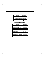
Many of Table 0-1 HP-UX learning products are referred to in this book.
Others in this list may be useful in helping you to make better use of your
system.
Table 0-1. HP-UX Learning Products
Title
HP part number
HP-UX Reference
B2355-90004
System Administration Tasks
B2355-90003
Installation Guide for HP Apollo 9000 Model 750 Workstations
and Servers
A1961-90001
Installing Peripherals
B2355-90006
E/ISA Conguration Guide for HP-UX: HP 9000 Series 700
Computers
B2355-90012
A Beginner's Guide to HP-UX
B1862-90000
A User's Guide to HP-UX Shells
B1862-90017
HP Visual User Environment User's Guide
B1171-90022
The HP Visual User Environment System Administration
Manual
B1171-90023
Using the X Window System
B1171-90037
Using DEX and SAX with HP-UX
A1926-90002
Managing Clusters of HP 9000 Computers
B2355-90009
How HP-UX Works: Concepts for the System Administrator
B2355-90005
Installing and Updating HP-UX
B2355-90000
HP-UX System Security
B1862-90009
Solving HP-UX Problems
B1862-90010
ix
Welcome!
Welcome to the worldwide community of HP Apollo workstation users.
The HP Apollo 9000 Model 750 Owner's Guide describes your HP Apollo 9000
Model 750 computer. It also refers to other documents that you have received
with your computer and its system software or which you may order separately.
In this section you will nd information about the organization of this guide
and the audience for which it is intended. You will also nd references to other
documents and directions for you to comment upon or ask questions about this
guide.
How to Use This Guide
Use this guide to learn about these things:
how to start up your system
how to interact with your computer
how to change your computer's conguration by adding, replacing, or
removing internal parts like memory cards and disk drives
how to determine the cause of problems with the system hardware
This guide will either give specic directions for each of these matters or direct
you to other documents or online resources that will explain how to do these
things.
When to Use This Guide
Use this guide after you have installed your system. To install your system
follow the instructions in the Installation Guide for HP Apollo 9000 Model 750
Workstations and Servers .
x
How This Guide Is Organized
Each chapter contains specic information about your system.
Read Chapter 1 to learn about your computer's parts, connectors, switches,
controls and indicators.
Read Chapter 2 to learn how to turn on the power, log in, log out and turn
o the power safely.
Read Chapter 3 to learn about the human interfaces that come with your
system. This chapter will help you decide if you wish to use the HP Visual
User Environment or an HP-UX shell to control your computer. This
chapter also contains a guide to the use of the Boot Console User Interface, a
program that allows you to change your system's conguration and behavior.
Read Chapter 4 to learn how to protect your computer's most precious
resource|its le system.
Read Chapter 5 to learn how to add, replace, or remove memory and internal
peripheral devices.
Read Chapter 6 to learn how to diagnose hardware problems and to
learn when and how to ask for assistance from your designated service
representative
xi
Audience
This guide is intended for use by service personnel and owners of HP Apollo
9000 Model 750 computers.
Read Me
Documents
Please refer to the release documents you received with your system. These
documents have titles that begin with the phrase \Read Me ." In these
documents you will nd information that may not have been included in this
guide at the time of its publication.
Problems, Questions, and Suggestions
We appreciate comments from the people who use our computer systems. Use
the Reader Response Card contained in this guide to submit comments about
the guide.
Getting Help
You may need assistance from time to time. In this manual, the person who
provides help is called the designated service representative. Check with the
appropriate party (your purchasing department, for example) to nd out where
to request service.
xii
Typeface Conventions
Unless otherwise noted in the text, this guide uses the following typeface
conventions.
term
Marks the rst appearance of a word and phrase that is used as
terminology. Terms are explained immediately or dened further in a
glossary.
Example: The practice of copying les onto other media for safe storage is
called backup.
Menu Item
The label of a menu item.
Example: Select Network Conguration Tasks to continue.
computer output
Indicates one of the following:
Text output from a computer system, usually appearing on a terminal
screen. Example:
Console login:
The literal name of software elements, such as les and programs. For
example: \The /etc/config program . . . "
user input
Text that is to be typed into a computer system by a user. Example:
$ pwd
variable name
A variable whose value must be supplied by the user.
Example: cp is a command entered by the user, and lename1 and
lename2 represent the names of the arguments to the command:
$ cp lename1 lename2
emphasized text
A point of emphasis.
Example: Back up all les before proceeding further.
4Keycap5
The character(s) printed on a keycap.
Example: 4Return5
FFFFFFFFFFFFFFFFFFFFFFFFFFFF
Function Key
This indicates the label of a function key as it appears at the bottom of a
terminal screen or window.
FFFFFFFFFFFFFFFFFFFFFFFFFFFF
Example: PERFORM TASK
xiii
Emissions Regulations
Federal Communications Commission (FCC)
The Federal Communications Commission of the U.S. government regulates
the radio frequency energy emanated by computing devices through published
regulations. These regulations specify the limits of radio frequency emission to
protect radio and television reception. All HP Apollo nodes and peripherals
have been tested and comply with these limits. The FCC regulations also
require that computing devices used in the U.S. display the agency's label and
that the related documentation include the following statement.
WARNING: This equipment generates, uses, and may emit radio frequency
energy and, if not installed and used in accordance with these instructions, may
cause interference to radio communications. It has been tested and found to
comply with the limits for a Class A computing device pursuant to Subpart J
of Part 15 of FCC Rules, which are designed to provide reasonable protection
against such interference when operated in a commercial environment.
Operation of this equipment in a residential area is likely to cause interference,
in which case the user at his own expense will be required to take whatever
measures may be required to correct the interference.
Compliance to these regulations requires the use of shielded cables.
Canadian Department of Communications (DOC)
This digital apparatus does not exceed the Class A limits for radio noise
emissions from digital apparatus as set out in the Radio Interference
Requirements of the Canadian Department of Communications.
Compliance to these regulations requires the use of shielded cables.
xiv
Verband Deutscher Elektrotechniker (VDE)
Herstellerbescheinigung
Hiermit wird bescheinigt, da dieses Gerat in Ubereinstimmung
mit den
Bestimmungen der Postverfugung 1046/84 funkentstort ist. Der Deutschen
Bundespost wurde das Inverkehrbringen dieses Gerates angezeigt und die
Berechtigung zur Uberpr
ufung der Serie auf Einhaltung der Bestimmungen
eingeraumt.
Die Einhaltung dieser Grenzwerte schreibt den Gebrauch abgeschirmter
Kabel vor.
VCCI Class 1 ITE Equipment
xv
Emissions Regulations Compliance
Any third-party I/O device installed in HP Apollo system(s) must be in
accordance with the requirements set forth in the preceding Emissions
Regulations statements. In the event that a third-party noncompliant I/O
device is installed, the customer assumes all responsibility and liability arising
therefrom.
Compliance to these regulations requires the use of shielded cables.
xvi
1
Your HP Apollo 9000 Model 750 Computer
This chapter provides an introduction to your HP Apollo 9000 Model 750
computer and its components. It describes the following:
The locations of the system unit's switches and LED indicators
How to interpret the LED indicators
The mass storage device bays
The parts of the rear of the system unit, including:
The system bulkhead and its connectors
The EISA card faceplate(s)
The graphic device bulkhead(s)
The power supply bulkhead
Your HP Apollo 9000 Model 750 Computer
1-1
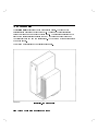
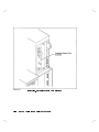
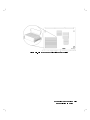
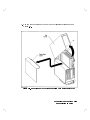
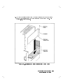
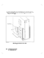
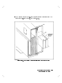
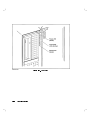
The System Unit
The system unit is contains the computer system itself. The front of the
central section contains the disk drive bays. The rear of the central section
holds the system card and graphic device cards. The \shoulder" section to the
right of the central section contains the EISA (Extended Industry Standard
Architecture) card bay and the cooling fans. At the bottom of the entire unit is
the power supply.
The system unit is intended for deskside placement.
Figure 1-1. The System Unit
1-2
Your HP Apollo 9000 Model 750 Computer
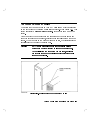
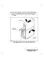
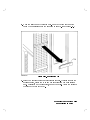
The Power On/Standby Switch
The switch that you use to turn on your HP Apollo 9000 Model 750 is located
on the in the front of the system unit's right \shoulder." (See Figure 1-2.) This
switch is actually a power on/standby switch. It is not the same as a power
switch.
When you attach the power cable to the connector on the power supply and
plug that cable into a power source, electric power is available from the power
supply. When you turn on the power on/standby switch, that electrical power
is distributed to the rest of the system unit.
Warning
Do
not
assume that all power to the computer is off just
because the power on/standby switch has been turned off.
To completely remove power from you computer, unplug the
power cable from the power outlet and disconnect that cable
from the power supply.
Figure 1-2. Location of the Power On/Standby Switch
Your HP Apollo 9000 Model 750 Computer
1-3
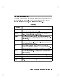
Understanding the LEDs
In the front of the system unit's center section is a hinged cover. When the
cover is closed, ve LEDs can be viewed through small \windows". Beside each
window is a symbol indicating the meaning associated with the activity of each
LED. Table 1-1 describes the activity of the lights when the HP-UX operating
system is running on your computer.
Table 1-1. LED Symbols and Their Meanings
Symbol
Note
1-4
Meaning
LED Activity
On/O
Power on/standby
Flashing
Transmitting to LAN
Flashing
Receiving from LAN
Flashing
Disk activity
Slow ash
System \heartbeat"
If you have been working on your system successfully, and the
\heartbeat" LED remains o or on for a long period of time,
it may mean that your system is \hung" (incapable of further
processing). See Chapter 6 for suggestions on how to deal with
this condition.
Your HP Apollo 9000 Model 750 Computer
Figure 1-3. LED Windows
Note
It takes a substantial amount of time (2|5 minutes) for your
computer to start the HP-UX operating system. During this
time, the behavior of these LED indicators (and the others
hidden behind the cover) is not controlled by HP-UX. Do not
interpret the behavior of the LEDS as illustrated by Table 1-1
until after HP-UX has nished booting.
Your HP Apollo 9000 Model 750 Computer
1-5
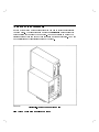
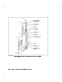
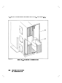
The Back of the System Unit
In back of the system unit are connectors you can use to attach peripherals to
your computer. The connectors are mounted on bulkheads: metal panels that
cover portions of the rear of the computer. You can get access to most of the
internal parts of your computer by removing some of these bulkheads. You will
nd descriptions of these internal parts in Chapter 5.
Figure 1-4. The Back of the System Unit
1-6
Your HP Apollo 9000 Model 750 Computer
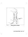
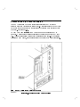
The System Bulkhead
The system bulkhead is the rightmost and tallest of the bulkheads in the back
of the system. (See Figure 1-4.) The I/O connectors and switches on this
bulkhead are listed in Table 1-2 and illustrated in Figure 1-5.
Table 1-2.
I/O Connector
or Switch
Use
SCSI
Used to attach external devices to the builtin SCSI (Small
Computer Systems Interface) controller.
HP-HIL
Used to connect HP-HIL (Human Interface Link) devices to the
system. The keyboard is an HP-HIL device.
Parallel
Used to connect external devices to the builtin parallel interface.
Many printers are have parallel interfaces which may be used with
this connector.
Thin LAN
Used to attach the system to an Ethernet LAN (Local Area
Network) that uses a BNC-type connector. Either this connector or
the AUI connector may be used.
AUI
Used to attach the system to an Ethernet LAN (Local Area
Network) that requires an external MAU (Medium Access Unit).
Either this connector or the Thin LAN connector may be used.
RS-232
Each of these connectors may be used to connect external devices to
the builtin serial interfaces. Most printers and modems can use
these connectors.
Audio
Used to drive an external speaker or other audio device.
Reset switch
Restarts the computer by resetting the operating system.
Service/Normal Used only during manufacturing. You will not need to use this
switch.
switch
Your HP Apollo 9000 Model 750 Computer
1-7
Figure 1-5. Connectors Mounted on the System Bulkhead
1-8
Your HP Apollo 9000 Model 750 Computer
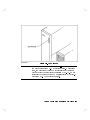
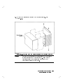
The Power Supply Bulkhead
This covers the power supply. It has a plug connector for the power cord. The
power supply bulkhead is below the other bulkheads at the bottom of the
system unit as you view it from the rear. See Figure 1-6.
Figure 1-6. The Power Supply Bulkhead
Your HP Apollo 9000 Model 750 Computer
1-9
Graphic Device Bulkheads
If your computer system includes a bitmapped display, you will nd the
bulkhead for a graphic device to the left of the system bulkhead in the upper
portion of the system unit. Your system may be equipped with two graphic
display devices; if so, there may be two graphic device bulkheads.
If your system is a server, it will probably not have any graphic devices at this
location.
You can have any of three types of graphic device in your computer:
Color graphic This type of device has three BNC connectors (one for each for
red, blue, and green). (See Figure 1-7). These are connected
card
by a cable to three similar connectors on a color display
monitor.
Grayscale
This type of device has one BNC connector. (See Figure 1-8).
graphic card This is connected by a cable to a similar connector on a
grayscale display monitor.
Graphic
This type of device has a special connector. (See Figure 1-9.)
interface card It is connected to an external graphic processor, which in turn
is connected to a video display monitor.
1-10
Your HP Apollo 9000 Model 750 Computer
Figure 1-7. Color Graphic Card Bulkhead
Your HP Apollo 9000 Model 750 Computer
1-11
Figure 1-8. Grayscale Graphic Card Bulkhead
1-12
Your HP Apollo 9000 Model 750 Computer
Figure 1-9. Graphic Interface Card Bulkhead
Your HP Apollo 9000 Model 750 Computer
1-13
Access to the EISA Card Faceplates
Your HP Apollo 9000 Model 750 includes four slots for EISA (Extended
Industry Standard Architecture) circuit cards. These slots are in the EISA card
bay above the power supply on the left side of the system unit (as viewed from
the back). See Figure 1-10.
An EISA card has a faceplate upon which one or more connectors may be
mounted. There are four vertical openings in the rear panel of the EISA card
bay. These openings allow access to the faceplates of the cards. If your system
contains no EISA cards, the openings should be covered with blank faceplates.
1-14
Your HP Apollo 9000 Model 750 Computer
Figure 1-10. Openings for EISA Card Faceplates
The Monitor and Its Controls
The monitor is the bitmapped video display device for your HP Apollo 9000
Model 750 computer. It may be attached directly to a graphic card in your
computer, or it may be attached to an external graphic processor. If your HP
Apollo 9000 Model 750 is congured as a server, it will probably not have a
monitor; see \Console Terminal", below.
Before using your monitor, you should become familiar with the controls and
indicators. For detailed information, see the installation instructions that are
packaged with your monitor.
Console Terminal
If your HP Apollo 9000 Model 750 computer is congured as a server, it
probably will not have a bitmapped display. Instead, it will use a video display
terminal connected to Serial Port A on the I/O bulkhead.
Before using your monitor, you should become familiar with the controls
and indicators. For details on the operation of your console terminal, see the
installation and operating instructions that are packaged with the terminal.
Your HP Apollo 9000 Model 750 Computer
1-15
2
Starting Up Your Computer
This chapter tells you how to boot HP-UX and get started with the HP Visual
User Environment. It describes the following:
How to boot (start up) the HP-UX operating system on your computer
How to log in (start a work session) as the root user
How to log out (end a work session)
How to create a new user account for yourself
How to shut down your computer and turn o the power safely
Are You Ready?
This chapter assumes the following:
Your computer is equipped with a bitmapped display. If it is not, you
will probably use a text terminal as your system console. Consult \About
Shells" in Chapter 3 and A Beginner's Guide to HP-UX for information
about basic interaction with the shell (command-line interface). See System
Administration Tasks manual for information on managing your system.
Your computer hardware has been unpacked and installed (including
computer, keyboard, monitor, and any external peripherals) according
to the instructions in Installation Guide for HP Apollo 9000 Model 750
Workstations and Servers .
If your computer is connected to a local area network, the physical
connection to the network has been made.
If your computer is a member of an HP-UX cluster, it has been added to
the cluster according to the instructions in Managing Clusters of HP 9000
Computers .
Starting Up Your Computer
2-1
You know where your system unit's power on/standby switch is. Refer to
Figure 1-2. You should also be able to locate the power switches for the
monitor and the external graphic processor, if your system includes these
components.
The HP-UX system software is installed and ready to boot. This will be true
in either of the following cases:
Your computer was delivered with the following software preinstalled on its
disks:
The HP-UX Operating System, Release 8.05 (or later)
The X Window System, Version 11, Release 4 (or later)
The HP Visual User Environment (VUE)
You have installed HP-UX from tape according to the instructions in
Installing and Updating HP-UX .
If your software is not yet installed, please install it before proceeding
further.
Before Turning On the Power for the First Time
If you are turning on your computer for the rst time, you will be asked for
some information about your system. You should know the following things:
The system name of your computer. This is sometimes called the host name.
The system name should not exceed eight characters in length. Obtain a
system name from your system administrator.
The time zone where your computer is located.
If you are connecting your system to a local area network, you will also need to
know this:
The internet protocol address (or IP address) of your computer. This is a
four-element code that uniquely identies your computer among all those
located on your network (or anyone else's). Obtain this address from your
network administrator.
Have this information at hand when you turn on the power for the rst time.
Enter the information when your system requests it. If you do not have the
information when prompted for it, the system will allow you to exit and restart
the system at another time when you can have the information ready at hand.
2-2
Starting Up Your Computer
Booting HP-UX
When you turn on the power to your computer, it will boot the HP-UX
operating system. The expression \boot" is short for \bootstrap;" the
computer loads a sequence of programs, each enabling more of the system
than the previous program. Thus the computer \pulls itself up by its own
bootstraps."
A computer's operating system is a set of programs that controls the execution
of other programs. HP-UX is a multitasking operating system because it
allows your computer to run many programs simultaneously. HP-UX is also a
multiuser system because it allows a number of dierent users to run programs
at the same time.
Once HP-UX is running on your system, you must log in as a user. If you
are accustomed to working on single-user personal computers, this may strike
you as odd, especially if you are the only user of your machine. However, the
process of user login is one of the ways that HP-UX prevents unauthorized
persons from using your system. This is especially important if your system is
attached to a network.
Turning On the Power
Turn on the power to the monitor and any external peripherals rst. If
necessary, wait for any external disk drives to come up to speed. (The
installation documents that are supplied with the external drives will explain
this.)
After the monitor and any other external devices have been turned on, turn on
the computer.
HP-UX Starts Up
After about three minutes, many messages appear on your screen. These
messages convey information about the various hardware and software
subsystems that are being activated by the bootup process. Unless something
is wrong with your system, you will not have to respond to any of these
messages.
Starting Up Your Computer
2-3
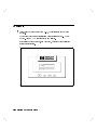
Logging In
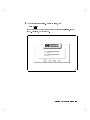
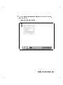
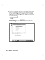
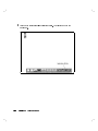
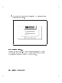
1
After your computer has booted HP-UX, the login screen shown below
appears.
This means your hardware installation was successful and HP-UX has
booted. Your HP VUE has also loaded and started.
If this screen does not appear, see Chapter 6, or contact your designated
service representative.
2-4
d
a
c
b
Starting Up Your Computer
2
You must rst login as root. To login as root, type:
root 4Return5
If you have given your computer a hostname other than unknown, skip to
step 4. Otherwise, go on to step 3.
d
a
c
b
Starting Up Your Computer
2-5
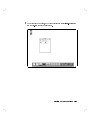
3
If a window appears over your login screen cautioning you about your
computer's hostname being unknown, you may continue and start HP VUE.
Move your mouse to put the pointer on the Start HP VUE screen button,
then click the left mouse button once.
NNNNNNNNNNNNNNNNNNNNNNNNNNNNNNNNNNN
Caution
Later, you should use the /etc/setparms program to enter a
host name for your system.
NNNNNNNNNNNNNNNNNNNNNNNNNNNNNNNN
You should not click on the No Windows screen button until
you have learned how to read and edit les.
2-6
d
a
c
b
Starting Up Your Computer
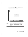
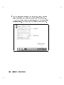
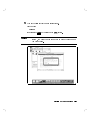
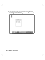
4
The copyright screen shown below appears.
Your HP VUE workspace (the screen environment in which you interact with
HP-UX) appears in about one minute.
The windows displayed on your screen may not be exactly like
those shown in this manual.
Note
d
a
c
b
Starting Up Your Computer
2-7
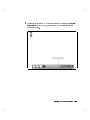
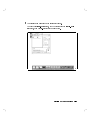
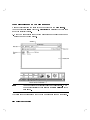
5
A screen similar to this one appears, with a console icon, two le manager
windows, a window entitled \Fasten Your Seatbelt," and the workspace
manager. The workspace manager is also known as the control panel.
Move the mouse pointer into the le manager window for the
/usr/demos/bin directory. It contains the icons (small pictures) for the
demonstrations. To run a demonstration, move the mouse pointer over an
icon, and press and release the left mouse button twice quickly. This is called
\double-clicking."
Place the pointer over the screen button labeled \Continue," and \click" the
left mouse button once by pressing and releasing it. This will close the
\Fasten Your Seatbelt" window.
Close the le manager window for the demonstrations by double-clicking on
its window menu button. Move the mouse pointer over the minimize button
in the other le manager window and double-click on it. This will turn the
window into a le manager icon. Move the mouse pointer over the console
icon, and double-click on it.
2-8
d
a
c
b
Starting Up Your Computer
6
The console icon disappears and is replaced by the console window. This is a
terminal window. It behaves just like any text terminal. You may type a
command into it, and it will print the results of the command's execution.
For the moment, though, you will use another feature of the HP Visual User
Environment: the Help System. Through interaction with the Help System,
you may learn about HP VUE.
Move the pointer to the help screen button. It's along the bottom of the
control panel, and it has a question mark (\?") on it. Click the left mouse
button once.
d
a
c
b
Starting Up Your Computer
2-9
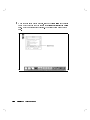
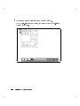
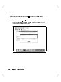
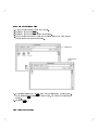
7
The Help Index window shown below appears.
Move the mouse pointer into the window and onto the line
A Tutorial for New Users
and click the left mouse button once to bring the next index into the
window. Then click the left mouse button once on the Viewer screen button
to see the help information.
NNNNNNNNNNNNNNNNNN
2-10
d
a
c
b
Starting Up Your Computer
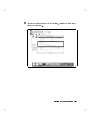
8
The rst part of A Tutorial for New Users is displayed in the Help Viewer
window. To see more of the text, you must use the scroll bar. You need not
read all the information now. See HP Visual Environment User's Guide for
information on using the scroll bar.
Close the Help Viewer window by moving the mouse pointer over the window
menu button in the upper left-hand corner of the window and double-clicking
the left mouse button.
Close the Help Index window in the same way. Turn the Console window
into an icon by clicking on its minimize button.
d
a
c
b
Starting Up Your Computer
2-11
Logging Out
1
To logout, move your pointer onto the control panel's lower right-hand bar.
This bar is called the logout button. Click the left mouse button once.
Notice that the progress light on the logout button begins to blink. This
indicates that the logout process has begun.
2-12
d
a
c
b
Starting Up Your Computer
2
This conrmation box will appear. To conrm your logout, click on the
screen button marked \OK."
A short time later, the login screen will reappear.
d
a
c
b
Caution
Do not turn o the power to your computer without rst
performing the shutdown procedures described in \Shutting
Down Your Computer". If you do not shut down your
computer properly, you may damage the programs and data on
your disk.
Starting Up Your Computer
2-13
Creating a New User Account
1
To create a new user account that you will normally use, you must rst login
as root.
Caution
2-14
root is a user account with special privileges and dangers.
Only the system administrator should regularly login as root.
d
a
c
b
Starting Up Your Computer
2
Activate the Help System by moving the pointer to the control panel's help
screen button (on the bottom, marked with a \?") and clicking the left
mouse button once.
d
a
c
b
Starting Up Your Computer
2-15
3
2-16
When the Help Index window appears, click on the down arrow in the scroll
bar to move the text so that you can see the System Administration Tasks
entry. Move your pointer onto this entry. Then click the left mouse button
once.
d
a
c
b
Starting Up Your Computer
4
When the System Administration Tasks Help Topic window appears,
select and click on
d
Creating a New User Account
a
c
b
Starting Up Your Computer
2-17
5
Read the instructions for creating a new user account. Click on the down
arrow and up arrow in the scroll bar to scroll through the instructions.
When you have nished reading the instructions, click on the control panel's
application button. That button has a few sheets of paper pictured on it.
2-18
d
a
c
b
Starting Up Your Computer
6
You will see a le manager window similar to this one.
To open the system_apps folder, move the pointer onto the system_apps
folder icon, then double-click the left mouse button.
d
a
c
b
Starting Up Your Computer
2-19
7
You will see a system applications window similar to this one.
Open the sys_admin folder by putting the pointer on it and double-clicking
the left mouse button.
2-20
d
a
c
b
Starting Up Your Computer
8
This system administration window appears.
Move your pointer onto the System Administration Manager (SAM) icon and
double-click the left mouse button.
d
a
c
b
Starting Up Your Computer
2-21
9
The System Administration Manager (SAM) is a application that is designed
to run on text terminals. If you wish to move the highlight bar to another
item, you must use the cursor keys. To press a softkey, you may either use
the function keys on your keyboard or use the mouse to click on the softkeys
in SAM's terminal window.
With this item highlighted,
Users ->
NNNNNNNNNNNNNNNNNNNNNNNNNNNNNNNN
move the mouse pointer over the Select Item softkey and click the left
mouse button once.
2-22
d
a
c
b
Starting Up Your Computer
10
When this window appears, this line will be highlighted:
Add a New User Account to the System
NNNNNNNNNNNNNNNNNNNNNNNNNNNNNNNN
Move the mouse pointer over the Select Item softkey and click the left
mouse button once.
d
a
c
b
Starting Up Your Computer
2-23
11
Type the login name you want to use for normal work, for example:
wizard
Note that some items are set to their default values. Normally, these need
not be changed.
NNNNNNNNNNNNNNNNNNNNNNNNNNNNNNNNNNN
Click on the Perform Task softkey.
2-24
d
a
c
b
Starting Up Your Computer
12
Type in the password for your new login account.
For example:
123four
NNNNNNNNNNNNN
then press the 4Return5 key or click on the Done softkey.
Caution
Remember your password! If you forget your password for the
system, you won't be able to log back in under the login name
you have chosen.
d
a
c
b
Starting Up Your Computer
2-25
NNNNNNNNNNNNN
13
Reenter the password, then press 4Return5 or click on the Done softkey.
The new user will be added to the system while this message is displayed:
Adding user user name...
You should also create a password for root. Refer to Appendix A of the HP
Visual User Environment User's Guide .
2-26
d
a
c
b
Starting Up Your Computer
14
After the new user has been added to the system, press the keyboard space
bar to get a blank form.
d
a
c
b
Starting Up Your Computer
2-27
NNNNNNNNNNNNNNNNNNNNNNNNNN
15
2-28
Click on the Main Menu softkey.
d
a
c
b
Starting Up Your Computer
NNNNNNNNNNNNNNNNNNNNNNNN
16
Click on the Exit SAM softkey.
To close the Permanent Terminal Window, move the mouse pointer over the
window menu button in its upper left-hand corner and double-click the left
mouse button.
d
a
c
b
Starting Up Your Computer
2-29
Setting a New Password
In addition to setting a password when you set up a regular user account, you
will want to change your password from time to time as a matter of good
security practice.
A password must meet four criteria to be valid:
Contain at least six characters.
At least two characters must be alphabetic.
At least one character must be a number (0-9) or a special character (/, ?, !,
or other punctuation mark).
Dier from your previous password by at least three characters.
Your password is case-sensitive, so the password ?Secret is dierent from the
password ?secret. Your password can also be as long as you want, but only
the rst eight characters are checked.
To set a password using VUE:
1. Click the applications directory button on the Workspace Manager to
display the applications directory.
2. Double-click the system_apps folder to open that subdirectory.
3. Double-click the sys_admin folder.
4. Double-click the PASSWORD icon to start that application.
5. Type your new password after the New password prompt and press 4Return5.
What you type doesn't appear on the screen.
6. Verify your new password, as requested, by retyping it and pressing 4Return5.
NNNNNNNNNNNNNNNNNNNNNNNNNNNNNNNNNNN
NNNNNNNNNNNNNNNNNNNNNNNNNNNNN
NNNNNNNNNNNNNNNNNNNNNNNNNN
Use the same procedure to change an old password as to add a new password.
If you already have one, you will be prompted appropriately for the old
password.
2-30
Starting Up Your Computer
Shutting Down Your Computer
Caution
Do not turn o the power to your computer without rst doing
these shutdown procedures. If you do not shut down your
computer properly, you may damage the programs and data on
your disk.
When you need to shut down your computer so it can be powered o, you
should follow these steps. Doing this will ensure that your le system remains
intact and that you can power-up and login correctly.
1
You must be logged in as root. If you are not, logout, then login as root.
d
a
c
b
Starting Up Your Computer
2-31
2
2-32
Click on the control panel's application button. That's the one with the
pages on it.
d
a
c
b
Starting Up Your Computer
3
When this window appears, move your pointer onto the system_apps folder
and double-click the left mouse button.
d
a
c
b
Starting Up Your Computer
2-33
4
2-34
When this window appears, move your pointer onto the sys_admin folder,
then double-click the left mouse button.
d
a
c
b
Starting Up Your Computer
5
When this window appears, double-click on the HALTSYS icon.
d
a
c
b
Starting Up Your Computer
2-35
6
When the Halt System window appears, click on the screen button marked
\OK, Halt System." Any other users who are logged onto your computer will
get a warning that the computer will soon be unavailable. In one minute, the
system will begin its shutdown process.
If you do not want to shut down your system, click on the screen button
marked \No, Cancel."
2-36
d
a
c
b
Starting Up Your Computer
7
The shutdown process takes about one minute.
These lines appear at the lower left-hand corner of your screen:
c
Halted (in a tight loop) -- OK To Hit Reset Button
b
You may now turn o your computer.
Starting Up Your Computer
2-37
8
The next time you turn on your computer, its HP VUE login screen should
appear within ve minutes.
d
a
c
b
For More Information . . .
To learn more about the HP-UX window environments, refer to HP Visual
User Environment User's Guide , The HP Visual User Environment System
Administration Manual and Using the X Window System .
2-38
Starting Up Your Computer
3
Using Your Computer
This chapter will help you decide how to interact with your HP Apollo 9000
Model 750 computer. It describes the following:
System software interfaces
The two types of HP-UX user interfaces you may use:
HP Visual User Environment (HP VUE)
HP-UX shells
Sample interactions in each HP-UX user interface
Further resources for learning more about the HP-UX user interfaces
Note
If you purchased your HP Apollo 9000 Model 750 computer
with pre-loaded system software, it will start up in HP VUE. If
you prefer not to use HP VUE, you may disable it by following
the directions in \Disabling HP VUE from Your Computer" in
Appendix A of HP Visual User Environment User's Guide .
The system hardware interface
The boot console user interface
Tasks that you may accomplish by interacting directly with the hardware
Using Your Computer
3-1
About HP VUE
The HP Visual User Environment (HP VUE) is a graphical interface
through which you can communicate with your computer. It is similar to the
windowing systems that are used on many personal computers. However, since
the underlying operating system is HP-UX, you will be able to do much more
with this system than you could with a machine equipped with less capable
system software.
This added power does not mean that your computer must be dicult to
use. HP VUE allows users to accomplish the most common interactions by
manipulating graphical objects with a mouse, reducing the time it takes to
learn how to use HP-UX.
3-2
Using Your Computer
Working with HP VUE
The following examples are typical of tasks to be accomplished with HP VUE.
The details of the display appearance will dier from that of your computer;
these examples are only for the purpose of illustrating how you can interact
with HP VUE and to help you to decide whether you prefer to work with the
HP Visual User Environment or one of the shells.
Like other graphical user interfaces, HP VUE provides windows for various
applications that run on your computer. In a networked environment, some
of these applications may be running on other computers. The windows can
accept input from the keyboard, mouse and other devices and display the
applications in a variety of ways.
Many of the windows are under the control of managers, which are software
systems that determine the nature and style of your interactions with parts of
the HP-UX operating system. For more information about managers, see the
HP Visual User Environment User's Guide .
One of the managers, called the Workspace Manager, works with the system's
builtin terminal emulators to provide windows that act like the screens of text
terminals. When you open one of these terminal windows, you will be able to
use the command line interface, or \shell." For information on using a shell,
see \About Shells" later in this chapter.
Using Your Computer
3-3
About Directories and HP VUE File Managers
Manage the information you store in your computer with the le manager.
Your computer uses les to hold data. Directories are \folders" that hold les
and other directory folders.
1. Move the mouse pointer over the le manager icon and press the left mouse
button to open the le manager.
Note
Your computer shows dierent les than those pictured. The
le manager illustrated here displays the home directory of the
user patti.
The following examples assume that two le managers are open on the screen.
3-4
Using Your Computer
Example 1: Moving a File
1. If your two le manager views overlap, move the overlapping view below the
underlying view by moving the mouse pointer onto the title bar (marked
File Manager) of the overlapping window, pressing and holding down the
left mouse button , dragging the window away from the underlying window so
you can see the display areas of both, and releasing the mouse button.
2. Press and hold down the middle mouse button on the le to be moved from
one of the le managers.
3. Drag the le to the other le manager display area, ensuring that it is over
an empty area.
4. Drop the le (release the mouse button).
Using Your Computer
3-5
Example 2: Copying a File
1.
2.
3.
4.
Move the pointer over the le to be copied.
Press and hold down 4CTRL5.
Press and hold down the middle mouse button .
Drag the le over an empty area in the display area of the le manager
window into which it is to be copied.
5. While still holding down 4CTRL5, drop the le (release the mouse button).
If you release 4CTRL5 before the mouse button, the le is moved instead of
copied.
6. Release 4CTRL5.
3-6
Using Your Computer
Learning More about HP VUE
To learn more about the HP Visual User Environment, read the HP Visual
User Environment User's Guide . This book explains many of the features of
the dierent HP VUE managers and provides examples of how they may be
used.
Using Your Computer
3-7
About Shells
In systems equipped only with text terminals, HP-UX usually communicates
with the user through a shell. A shell is a program that captures text typed
on the terminal's keyboard, interprets the text into commands and data,
transmits the commands to the operating system, and prints the results of the
commands' execution (and any resulting messages) on the terminal's screen. A
shell is sometimes also called a command interpreter or command processor.
When you interact with your computer using the entire screen as a terminal
(that is, if you do not use OSF/Motif or another window environment), you
will use the shell in much the same way you would if you were working on a
text terminal.
If you set up your computer to run HP VUE or the OSF/Motif window
environment upon which it is based, each terminal window that you open with
hpterm or xterm runs a shell program. You may open many terminal windows,
and they may communicate with your computer's processor or the processors of
other computers connected to a network.
Table 3-1 lists some of the features of the shells available in HP-UX.
3-8
Using Your Computer
Table 3-1. HP-UX Shells
Shell
Features
Bourne
Shell
The default shell for HP-UX. It is compatible with most of the shell
programs provided with your system.
Korn
Shell
An upwardly-compatible extension of the Bourne Shell, with many new
features:
A command history buer
Command aliases
Pathname completion
Job control
Interactive command-line editing
Key
Shell
An upwardly-compatible extension of the Korn Shell. It makes use of
softkeys function keys to \build" HP-UX command lines, which are
translated and executed automatically. Key Shell includes these features:
\Keystroke" execution of 22 commands
Softkey display of options for 70 common HP-UX commands
User-congurable status line
Context-sensitive help
Support for editing keys like 4Delete line5
C Shell
This shell has a command syntax that resembles the C programming
language. For this reason, it is often favored by C programmers.
Working with a Shell
The following examples are typical of tasks to be accomplished with a shell.
They work in the same way in any of the four shells.
The lenames used in the examples will dier from those that are on your
computer; these examples are only for the purpose of illustrating how you can
interact with an HP-UX shell and to help you to decide whether you prefer to
work with the HP Visual User Environment or one of the shells.
This is the general form of the HP-UX commands used in the examples:
command name argument(s)
Using Your Computer
3-9
The command name is the name of an HP-UX command. The argument is the
data that the command will act upon. There may be more than one argument .
In the following examples, all of the arguments are le names.
About Directories
You will understand the following examples better if you know something
about directories. In HP-UX, a le is a \container" for data. A directory is
a \container," too, but it contains les. A directory may also contain other
directories.
A le's location may be described by writing the \chain" of directories one
must pass through to nd the le. In HP-UX, the highest-level directory is
called the root directory. It is designated by the \slash" symbol:
/
A directory called users that is contained in the root directory is designated in
this way:
/users
The directory users is said to be a subdirectory of the root directory. It may
in turn contain other subdirectories. Here is how a users subdirectory called
terry is designated:
/users/terry
3-10
Using Your Computer
If /users/terry contains a le called myfile, this is how it is designated:
/users/terry/myfile
Because this describes the \path" one must follow from the root directory to
locate myfile, /users/terry/myfile is a path name.
Example 1: Moving Files
Use the mv command to move les from one directory to another. For example,
to move myfile into the projects directory, type:
$ cd
$ mv myfile projects
Move to your home directory rst.
Now verify that it worked:
List your current working directory.
Where did myfile go?
Look in the projects directory.
old/
There's myfile. It worked!
A single dot (.) for a path name represents your current working directory.
Therefore, to move myfile from the projects directory back to your current
working directory, type:
Don't forget the dot.
$ mv projects/myfile .
$ lsf
List your current working directory.
myfile
projects/
It worked; myfile is back.
$ lsf projects
List projects.
new/
old/
The le myfile isn't there anymore.
The general form of the mv command is as follows:
mv from path to path
where from path is the le name or path name of the le you want to move,
and to path is the name of the path to which you are moving.
$ lsf
projects/
$ lsf projects
myfile
new/
Using Your Computer
3-11
Example 2: Copying Files
To copy a le into a dierent directory, use the cp command. For example, to
make a copy of myfile named myfile2 in the projects directory, type:
$ cp myfile projects/myfile2
$ lsf
myfile
projects/
The le myfile still exists.
$ lsf projects
myfile2
new/ old/ The copy (myfile2) is in the projects directory.
To make a new version of myfile2 named myfile3 in your current directory,
type:
$ cp projects/myfile2 myfile3
$ lsf
myfile
myfile3
projects/
The general form of the cp command is as follows:
cp from path to path
where from path is the le name or path name of the le you want to copy, and
to path is the path name of the directory or le to which you are copying.
3-12
Using Your Computer
Changing Your Login Shell
If your system was installed for you, the installer may have chosen a shell for
you. If you prefer to use another shell, you may change your shell permanently
by using the chsh (change shell) command:
chsh username full shell name
where username is your user name and full shell name is the full path name of
the shell you want as your login shell. After you use the chsh command, you
must log out and log in again for the change to take eect. For example, if
the user terry changes the default login shell to the Korn Shell, the command
reads:
$ chsh terry /bin/ksh
Learning More about Shells
To learn more about the HP-UX shells, read A Beginner's Guide to HP-UX .
This book explains many of the features of the dierent shells and provides
examples of how they may be used. For a more detailed exploration, read A
User's Guide to HP-UX Shells , an extended tutorial on the uses of the shells.
For a technical description of the shells, see sh (1), ksh (1), keysh (1), and csh (1)
in HP-UX Reference .
Using Your Computer
3-13
The Boot Console User Interface
There will be time when you will want to interact directly with the hardware
of your computer before it boots the operating system. Your HP Apollo 9000
Model 750 provides a boot console user interface to allow you to perform
special tasks, display information, and set certain system parameters even if
the operating system is unavailable.
These are the special tasks you can perform:
Boot your computer from any specied hardware device.
Search for hardware devices that contain media from which your computer
can be booted.
Select an operating system for the next boot attempt.
Reset the computer.
These are the kinds of information your system can display:
A list of the commands you may issue from the boot console user interface
Help in using those commands
The real-time clock's time and date
The operating system selected
The settings of the Autoboot and Autosearch \ags"
The status (on or o) of the secure boot mode
The station address for the builtin LAN interface
The primary boot path
The alternate boot path
The console path
The keyboard path
The versions of the I/O modules (builtin, graphics, and EISA)
Your computer's model number
Your computer's processor frequency
Your computer's I/O subsystem frequency
Your computer's SCSI jumper frequency setting
Your computer's EISA jumper frequency setting
The status of the LAN jumper
The revision number of the processor
The revision number of the system controller
The revision number of the oating point coprocessor
These are the system parameters you can set:
3-14
Using Your Computer
The real-time clock's time and date
The operating system selected
The Autoboot and Autosearch \ags"
The status (on or o) of the secure boot mode
The primary boot path
The alternate boot path
The console path
The keyboard path
Using the Boot Console User Interface
To use the boot console user interface, follow these steps:
1. Shut down your computer. To do this, follow the steps listed in \Shutting
Down Your Computer" in Chapter 2. Wait until these words appear:
Halted (in a tight loop) -- OK To Hit Reset Button
2. Turn o the computer, wait a few seconds, then turn it back on.
3. Press the 4ESC5 key. In a few seconds, this message appears:
Terminating selection process.
A short time later, this message appears:
Searching for potential boot devices.
To terminate search, press and hold the ESCAPE key.
Device Selection Device Path Device Type and Utilities
-----------------------------------------------------------------------------
Your computer is now searching for devices that may hold le systems from
which it can boot HP-UX. As they are found, they appear in a list.
A list of devices might look like this:
P0
P1
P2
P3
P4
scsi.6.0
scsi.5.0
scsi.4.0
scsi.3.0
lan.123456-789abc
disk drive identier
disk drive identier
DDS-format tape drive identier
CD ROM drive identier
cluster server identier
Using Your Computer
3-15
This process may take several minutes. When the search ends, this list of
actions appears:
b)
s)
a)
x)
?)
Boot from specified device
Search for bootable devices
Enter boot administration mode
Exit and continue boot sequence
Help
Select from menu:
This is the boot console user interface menu.
If no devices are listed, take these actions:
Check for loose connections.
Check to make sure that all the SCSI bus addresses are unique for each
SCSI bus. Duplication of addresses may cause several or all of the
devices on the bus to be inaccessible, and it may lead to loss of data.
Check and verify that all peripherals are powered on.
If you have performed the address, connection, and power checks and
there are still no devices listed, there is a serious problem. Contact your
designated service representative for assistance.
If no disk devices are listed, and your system is equipped with disk drives,
then your computer is failing to communicate with its disks. Recheck the
SCSI connections and try again.
Of course, if your computer is a member of a cluster (a group of computers
that share the le system of a host by means of a network connection), there
may be no disks listed because your computer has no disks directly attached
to it.
Entering the Boot Administration Mode
To change system hardware parameters, you must enter the boot
administration mode. From within this mode, you may enter any of the
commands used in the task descriptions that follow.
To enter the boot administration mode, type:
Select from menu: a
3-16
Using Your Computer
This prompt is displayed:
BOOT_ADMIN>
Exiting the Boot Administration Mode
To exit the boot administration mode, take any of the following actions:
Type exit at the BOOT_ADMIN> prompt. This will return you to the boot
console user interface menu.
Type reset. This will restart the computer.
Issue a boot command. See \Booting the Computer" for details.
Turn o the computer. There is no need to shut down the computer with
the special procedure described in \Shutting Down Your Computer" in
Chapter 2, since the computer has not yet been booted, and the le system
has not been activated.
Getting Help on the Use of the Boot Console User Interface
Commands
You may issue many dierent commands in the boot administration mode. For
a complete listing of these commands, type:
BOOT_ADMIN> h
or
BOOT_ADMIN> help
or
BOOT_ADMIN> ?
A summary of all the commands appears on your screen.
To get help for a particular command, type:
BOOT_ADMIN> help command name
where command name is the name of one of the listed commands. The
displayed help information usually includes a description of the command, its
options, and the format for parameters.
Using Your Computer
3-17
Booting the Computer
Usually, you will start your computer by turning it on and waiting for HP-UX
to boot automatically. However, you may not wish for the usual sequence to
occur.
For example, you may wish to start your computer from an operating system
that is stored on a device that is dierent from your usual boot device. If
your normal operating system kernel (/hp-ux) or the disk on which it resides
becomes damaged or unusable, you may wish to boot from a dierent disk
or perhaps another type of device, such as a DDS-format tape drive or a
magneto-optical disk.
Here are some situations and examples:
If you know which device you want to boot from, and you know that it
contains a bootable operating system, type:
BOOT_ADMIN> boot device
where device is one of the following:
The hardware path to the device, specied in Mnemonic Style Notation.
(See Table 3-3 in the section \Displaying and Setting Paths" later in this
chapter for further information.)
The Pn designation of the device, as listed in the device search (see \Using
the Boot Console User Interface" or \Searching for Bootable Media").
For example, if you wish to boot an operating system that is stored on a
DDS-format tape in a drive that is located at scsi.4.0 and is designated by
the search as device P2, type:
BOOT_ADMIN> boot scsi.4.0
or
BOOT_ADMIN> boot P2
The operating system on the specied device will be used to start your
computer.
If you wish to interact with the Initial System Loader (ISL) before booting
your computer, type:
3-18
Using Your Computer
BOOT_ADMIN> boot device isl
This will cause the ISL to be loaded from the specied device. After a short
time, this prompt will appear on your screen:
ISL>
ISL is the program that actually controls the loading of the operating
system. By interacting with ISL, you can choose to load an alternate version
of the HP-UX operating system.
For example, if the usual kernel (/hp-ux) on your root disk (scsi.6.0) has
become corrupted, and you wish to boot your computer from the backup
kernel (/SYSBCKUP), type:
ISL> hpux boot disk(scsi.6;0)/SYSBCKUP
If you do not know the locations of the bootable operating systems on
the various media in your le system, you can nd out with the search
command (see \Searching for Bootable Media").
Note
You may also boot the computer from the main menu of the
Boot Console User Interface by using a command in this form:
Select from menu: b device
where device path is a designator for the path to the device
that contains a bootable le system.
Searching for Bootable Media
The initial search conducted by the boot console user interface locates devices
that might contain bootable media. This search might nd a DDS-format tape
drive which actually does not contain a bootable tape. To check to see which
devices actually contain bootable media, type:
BOOT_ADMIN> search
This will cause your computer to search exhaustively for bootable media. It
will search all types of I/O devices in this order:
1. builtin SCSI
2. builtin LAN
Using Your Computer
3-19
3. EISA cards
The search may turn up more devices than there are lines on your display. If
you are using a text terminal, you may control the progress of the search from
your terminal's keyboard:
To hold the display temporarily, press 4Control5-4S5.
To continue the display, press 4Control5-4Q5.
To halt the search, press 4Escape5.
These ow-control commands do not work with a bitmapped display, but such
a display can show more than forty lines of text, so you are unlikely to need
them.
Note
If the search discovers ten devices, the label in the Device
Selection column for the tenth entry will be labeled P9. Any
subsequent entries will be labeled P*.
P* cannot be used as a device designator for boot
administration commands because it is ambiguous. To refer to
a device labeled P* in a search, specify it by means of the entry
in the Device Path column.
To search to see which devices of just one type actually contain bootable media,
type:
BOOT_ADMIN> search device type
where device type is one of the following:
scsi
The builtin SCSI bus
lan
All connections to the builtin LAN
eisa
The EISA bus
Note
You may also search for bootable media from the main menu
of the Boot Console User Interface by using a command in this
form:
Select from menu: s
You may also use this form:
3-20
Using Your Computer
Select from menu: s device type
where device type is the type of device (scsi, lan, or eisa) for
which you wish to search.
Redisplaying the Results of a Search
The list of bootable devices is stored until you conduct another search or you
reboot your system. To see the list of devices again, type:
BOOT_ADMIN> show
It is much faster to redisplay the list with show than it is to conduct the search
again.
Displaying and Setting Paths
A path is the hardware address of a device that is attached to the I/O system
of your computer. The path command can set any of the following paths:
Table 3-2. System Paths
Path Name
Device
primary or pri Your computer's default boot device (usually the root disk)
alternate or
alt
Your computer's alternate boot device (usually a DDS-format tape
device)
console or con Your computer's primary display device
keyboard or
key
Your computer's primary ASCII input device
To display the current settings for the system paths, type:
BOOT_ADMIN> path
The paths will be displayed in Mnemonic Style Notation. This notation
displays paths in these formats:
Using Your Computer
3-21
Table 3-3. Mnemonic Style Notation
Specication Format
I/O Type
EISA SCSI
eisa.slot .scsi address .logical unit number
Other EISA/ISA
eisa.slot .other info 1
Builtin SCSI
scsi.scsi address .logical unit number
Builtin LAN
lan.server address .init timeout .io timeout
Builtin HIL
hil
RS-232 Port A
rs232_a.baud rate .word length .parity option
RS-232 Port B
rs232_b.baud rate .word length .parity option
Graphics slot
graphics_12 and graphics_23
Builtin parallel port parallel
1 See your SCSI card documentation for information about board-level
information, function blocks, choice blocks, attributes, and other EISA/ISA card
information.
2 The graphics_1 path maps to graphics slot 0 (the center slot in the top section
of the system unit, as viewed from the rear). This path is not supported for
HP-UX 8.05.
3 The graphics_2 path maps to graphics slot 1 (the leftmost slot in the top
section of the system unit, as viewed from the rear). This is the only graphics
path supported for HP-UX 8.05.
To display the current setting for a particular system path, type:
BOOT_ADMIN> path path type
where path type is one of the path types listed in Table 3-2. For example, to
get the path to the primary boot device, type:
BOOT_ADMIN> path primary
To set a system path to a new value, type:
BOOT_ADMIN> path path type path
where path type is one of the path types listed in Table 3-2 and path is
the specication of the path in Mnemonic Style Notation (as described in
3-22
Using Your Computer
Table 3-3. For example, to set the console path to RS-232 Port A with a baud
rate of 4800, a word length of 7, and even parity, type:
BOOT_ADMIN> path console rs232_a.4800.7.even
For help in using the path command, type:
BOOT_ADMIN> help path
or
BOOT_ADMIN> help path type
where path type is one of the path types listed in Table 3-2. The help screens
oer complete descriptions of all path options.
Selecting an Operating System
Your computer currently uses the HP-UX operating system, so it is set up
to load HP-UX. At some time in the future, you may decide to use the OSF
operating system.
To check which operating system your computer is currently congured to load,
type:
BOOT_ADMIN> os
Your computer will respond with one of the following:
HPUX or HP-UX Hewlett-Packard Unix
OSF
the Open Software Foundation's operating system
To set up your computer to load an OSF system, type:
BOOT_ADMIN> os osf
To set up your computer to load HP-UX again, type:
BOOT_ADMIN> os hpux
or
BOOT_ADMIN> os hp-ux
For this change in operating systems to take eect, you must reset your
computer (see \Resetting the Computer"), or turn it o and back on again.
Using Your Computer
3-23
Resetting the Computer
The act of resetting your computer causes it to restart completely. It's similar
to turning the computer o and then back on again. To reset your computer,
type:
BOOT_ADMIN> reset
Displaying and Setting the Real-time Clock
It is usually a good idea to set the real-time clock in your computer with the
HP-UX date command, since that command contains special safeguards that
can help you to avoid disruption of time-related processes (like those controlled
by the cron command). But you may set the clock from within the boot
administration mode if you wish.
To display the current setting of the real-time clock, type:
BOOT_ADMIN> date
Your computer will report the information in this form:
Mon Jul 1 14:55:05 GMT (19:91:07:01:14:44:05)
To set the real-time clock, type:
BOOT_ADMIN> date century:year:month:day:hour:minute:second
For example, to set the clock to July 1, 1991, 2:44:05 pm gmt, type:
BOOT_ADMIN> date 19:91:7:1:14:44:5
Note
3-24
The boot administration mode's date command only
\understands" Greenwich Mean Time (gmt). You must
compute gmt relative to your own time zone to get the correct
value for hours (and in some time zones, minutes as well).
Using Your Computer
Displaying and Setting the Autoboot and Autosearch Flags
Autoboot and Autosearch are ags (variables) stored in your computer's
non-volatile memory. (Non-volatile memory retains its contents even after
power is turned o.) If you reset these ags to new values, the change will take
eect the next time you reboot the computer.
To examine the state of the Autoboot and Autosearch ags, type:
BOOT_ADMIN> auto
If Autoboot is set to on, when your computer is turned on, it will
automatically attempt to boot the operating system. If it is set to off, your
computer will enter the boot console user interface instead.
To change the state of the Autoboot ag, type:
BOOT_ADMIN> autoboot state
where state is on or off.
If Autosearch is set to on, when your computer enters the boot console user
interface, a search for all potential bootable devices takes place.
To change the state of the Autosearch ag, type:
BOOT_ADMIN> autosearch state
where state is on or off.
Note
Set both Autoboot and Autosearch to on if you wish to have
your system boot automatically from the rst device it nds
in its search. If you wish to have your system come up in the
Boot Console User Interface instead, set both Autoboot and
Autosearch to off.
It is not recommended to set Autoboot and Autosearch to any
other combination of values.
Using Your Computer
3-25
Displaying and Setting the Secure Boot Mode
There may be circumstances in which you would not wish to allow anyone
to attempt to boot your computer from a device other than the device you
have specied, nor to control the system from any console other than the
one you have designated. This can be an important consideration in secure
installations.
If you set up your system in such a way that it is physically impossible for
unauthorized persons to disconnect it from its designated boot device(s), you
can guarantee that the boot console user interface cannot be used to boot
the system from an unauthorized device or to change the console path. If the
secure boot mode is set to on, the boot console interface cannot be activated;
thus you are assured that your system's security cannot be compromised
through interaction with that interface.
To check the status of the secure boot mode, type:
BOOT_ADMIN> secure
The value on or off will be displayed.
To set the secure boot mode to on, type:
BOOT_ADMIN> secure on
Resetting the Secure Boot Mode
Once the secure boot mode is set to on, the only way to reset it to off is to
disconnect the boot device(s). Follow these steps:
1. Shut down your computer, turn it o and disconnect the power cable.
2. Disconnect your computer from its boot device(s). This will probably
involve special procedures (specic to your site) for gaining access to the
boot device(s).
3. Turn on your computer. The boot console interface will reappear.
4. Enter the boot administration mode.
5. Type:
BOOT_ADMIN> secure off
3-26
Using Your Computer
6. Turn o your computer.
7. Reconnect the boot device(s).
8. Turn your system back on.
Displaying the LAN Station Address
The LAN station address of your computer is the label that uniquely identies
the LAN connection for your computer at the link level (the hardware level). It
is sometimes necessary for you to supply this address to others. For example, if
your computer is to become a member of a cluster, the cluster administrator
will need to know your LAN station address in order to add your computer to
the cluster.
To display your computer's LAN station address, type:
BOOT_ADMIN> lan_addr
The LAN station address will be displayed as a twelve-digit number in
hexidecimal notation, like this:
LAN Station Address: 123456-789abc
Using Your Computer
3-27
4
Protecting Your File System
The programs and data on your disks are of great value, and you should have
procedures in place to make periodic copies of them on another medium, such
as DDS tape. Such a copy of your le system is called a backup.
You may use a backup for several purposes:
to restore individual les you may have deleted accidentally
to restore all les in the event of a disk failure
A backup need not contain all the les on your system, and les may be copied
to or from it one at a time. You make a backup with the fbackup utility, and
it is restored with the frecover utility.
You can make a dierent type of backup (called a disk image) using the dd
command or a utility provided on the Support Medium. See \Creating a Disk
Image" and \Using the Backup System Disks Main Menu Option" in Chapter 6
for more information.
Note
You should back up your disks on a regular basis. See System
Administration Tasks for a complete discussion of the various
backup strategies and the correct use of fbackup.
Protecting Your File System
4-1
Protecting Your System from the Effects of a System
Crash
The most important use of a backup is to recover from a system crash. In the
most serious type of system crash, it is impossible to reboot your system from
the root disk because the data on the disk has been corrupted, or the disk itself
may have been damaged. In this situation, you must boot your computer from
an alternate device, such as a DDS tape drive.
You cannot boot your system from a backup. You can start your system only
from a bootable image on a disk or on a tape. A recovery system contains such
a bootable image, along with a small subset of your le system, just enough
to get your computer started after a disk failure. Unlike a backup, a recovery
system can be used to start your computer. Once you get the computer
operating again, you can restore all of your les from a backup.
For instructions on creating a recovery system, see \Creating a Recovery
System", the next section in this chapter. For instructions on using a recovery
system, see \Using the Recovery System" in Chapter 6.
Creating a Recovery System
You need some knowledge of device les to create a recovery system.
The DDS tape drive and the disks inside your system use device les to
receive and transmit data. The DDS tape drive uses the device le called
/dev/update.src
The procedure described here assumes that you are using a DDS tape drive to
create a recovery system. You may use other devices for the recovery system,
such as a magneto-optical disk or a spare hard disk. You may not use a oppy
disk, though, because it does not have enough storage capacity to hold the
recovery leset.
To create a recovery system:
1. Log in as superuser (root). See A Beginner's Guide to HP-UX for
information on how to log in from the shell prompt.
2. Prepare a DDS tape cassette for use as a recovery system. Make sure
that the cassette is not write-protected. To do this, check the rear of the
cassette. You will see a sliding tab in one corner. This tab is used to open
4-2
Protecting Your File System
and close the \recognition hole" in the cassette. If the hole is open, the
cassette is write-protected; if it is closed, data may be written on the tape.
If necessary, slide the tab to close the recognition hole.
3. Create the recovery system by using the mkrs command. mkrs has the form:
/etc/mkrs [-v] [-q] [-s] [-f rcdev] [-r rootdev] [-m series]
For example, if you are creating a recovery system on a DDS-format tape
drive associated with the device le /dev/rmt/0m, and the root device is
associated with the device le /dev/dsk/6s0 , type:
/etc/mkrs -v -q -s -f /dev/rmt/0m -r /dev/dsk/6s0
This will create a recovery system in /usr/tmp (on disk) and copy it over
to the DDS-format tape drive after it is \built." The recovery system will
contain a small but useful subset of the system les. Your system will print
a summary description of its actions on the screen as the recovery system is
being created.
Note
To use the -q option, you must have at least 10 megabytes of
space available in /usr/tmp.
See the following section, \Using the mkrs Script", for details on options and
defaults.
For the devices and options in the example command line, the process of
building a recovery system begins with this message:
Building a series 700 DAT recovery system on /dev/rmt/0m
for the disk corresponding to /dev/dsk/6s0
Are you sure you want to continue (y/n)?
4. To continue, press 4Y5 4Return5. To stop the process, press 4N5 4Return5.
If you continue, this message appears:
Place media in drive, once busy light remains off hit <Return>.
5. Put the DDS tape cassette into the system's tape drive.
6. When the tape has nished loading, press 4Return5.
Protecting Your File System
4-3
A series of messages follows, reporting the progress of the creation of the
recovery system. The process takes less than ten minutes. When the
recovery system is completed, the DDS-format tape drive will eject the
cassette.
If mkrs doesn't exist on your system (you'll receive a message file not
found), use the information on adding lesets in Chapter 5, \Updating
HP-UX", in Installing and Updating HP-UX , to add the aconfig leset to
your system.
7. Boot the recovery system to verify that it works. For this step, you will
need to shut down the system (see \Shutting Down Your Computer" in
Chapter 2). Once the system is turned o, follow the procedure in \Booting
the Recovery System" in Chapter 6 to boot the recovery system.
You probably will want to test-boot the recovery system during o hours if
other people use your system.
8. Put the recovery system in a safe place and lock it up.
When you boot using the recovery system, you come up as the root user.
This is potentially a serious security problem. It is up to you, the system
administrator, to keep this recovery system safe, so you can use it if you
need to, and unauthorized people can't get at it.
9. If you loaded the aconfig leset just to create a recovery system, you may
wish to recover the disk space used by aconfig.
To remove the leset, follow the instructions in \Removing System Files" in
System Administration Tasks .
4-4
Protecting Your File System
Using the mkrs Script
The mkrs command has the form:
mkrs [-v] [-q] [-s] [-f rcdev] [-r rootdev] [-m series]
where:
rcdev
is the name of the device le for the cartridge tape drive
on which you will create your recovery system. The mkrs
command will, by default, look for the following device les:
/dev/update.src
if it exits as a character device le, else
/dev/rct/c0
if it exits as a character device le, else
/dev/rct
if it exits as a character device le, else
the device le must be specied.
If none of the above defaults exists on your system, you must
either create one of them or specify the recovery device le
using the -f option. The recovery device le can be either a
block or a character device le. An error message will result if
the user does not use one of the defaults and does not specify a
recovery device le name.
The -v option species you want to see a running history of
the construction of the recovery system.
The -q option species that the recovery system's image
be created in the /tmp directory before being copied to the
recovery media (the -q option is the default for a DDS tape
recovery system). This option saves time due to seeking on
DDS tape media.
The -s option species that a smaller set of system les be
placed on the recovery media; this applies when making a
DDS tape recovery system for a small memory system. The -s
option is required when building a recovery system for a Series
700 computer on DDS-format media.
Protecting Your File System
4-5
rootdev
series
is the name of the device le for the root device. The mkrs
command will, by default, look for the following root device
les:
/dev/dsk/0s0 if it exists as a block device le, else
/dev/root
if it exists as a block device le, else
/dev/hd
if it exists as a block device le, else the device
le must be specied.
If none of the above defaults exists on your system, you must
either create one of them or specify the root device le using
the -r option. The root device le must be a block device le.
The character device le need not exist. An error message will
result if a default root device le does not exist and you do not
specify a root device le name.
Normally not needed. If mkrs cannot determine the type of
system you have it will send you an error message. If this
happens re-execute mkrs using the -m option with the value
700.
For example, if your root le system had the device le /dev/dsk/0s0, and you
were creating your recovery system on a cartridge tape drive which had the
device le /dev/update.src, you would type the following command:
mkrs
The mkrs process takes about ten minutes.
\Using the Recovery System" in Chapter 6 explains how to use the recovery
tape to restore your system.
For more information about /etc/mkrs, see the mkrs (1M) manual page in
HP-UX Reference .
4-6
Protecting Your File System
Backing Up Your Programs and Data
Your data is precious. Back it up often. Consult System Administration Tasks
for backup strategies.
There are two types of backups:
Backup tape A tape that contains copies of some or all the les on your
system.
Disk image
A bit-for-bit copy of your disk(s). Such an image is usually
made on some other medium (a DDS-format tape, for
example), but it may also be made on another disk.
Backup tapes and disk images dier from one another in one important way.
A backup tape need not contain all the les on your system, and les may be
copied to or from it one at a time. This is not possible with a disk image. A
backup tape is a more exible tool for maintaining the security of your data.
Making an Archive Backup
An archive backup contins all the les on your system. You should make an
archive copy of your le system as soon as your system is installed. If you
ordered your system with preinstalled software, you may not have access to the
installation tapes, so the only way you can be sure that you can restore all
your les is to make an archive of them immediately.
To make an archive copy of your le system:
1. Log in as root.
2. Open a terminal window.
3. Load a write-enabled medium (for example, a DDS-format tape) into the
backup device.
4. Type:
$ fbackup -f backup device -0 -v -i /
where backup device is the device le associated with the backup device.
For example, to back up all your les to a DDS-format tape in a tape drive
located at /dev/rmt/0m, type:
Protecting Your File System
4-7
$ fbackup -f /dev/rmt/0m -0 -v -i /
5. If fbackup requires more than one medium to complete the backup, it will
prompt you to insert one in the backup device.
You can use fbackup in many dierent ways to provide complete and ecient
backup of your le system. See System Administration Tasks for more
information.
Creating a Disk Image
You need some knowledge of device les to create a disk image. The DDS tape
drive and the disks inside your system use device les to receive and transmit
data. The DDS tape drive uses the device le called /dev/rmt/0mn. The root
(/) disk uses /dev/rdsk/6s0 , and the user (/usr) disk uses /dev/rdsk/5s0.
To create a disk image:
1. Shut down your system, and put it into single-user mode. To do this, log in
as root and type:
$ shutdown
After a one-minute pause, this will bring all processes on your computer to a
halt and cause it to reboot into a mode in which root is the only user.
Note
If other users are logged into your computer, they will receive a
message to the eect that their sessions will end in 60 seconds.
They will have to stop whatever they are doing and save any
open les.
2. Log in as superuser (root). See A Beginner's Guide to HP-UX for
information on how to log in from the shell prompt.
3. Put a DDS tape cassette into the system's tape drive. Make sure that the
cassette is not write-protected. To do this, check the rear of the cassette.
You will see a sliding tab in one corner. This tab is used to open and close
the \recognition hole" in the cassette. If the hole is open, the cassette
is write-protected; if it is closed, data may be written on the tape. If
necessary, slide the tab to close the recognition hole.
4. The command to copy a disk image onto tape looks like this:
4-8
Protecting Your File System
$ dd if=disk lename of=DDS tape device lename
If you want to copy the disk located at /dev/rdsk/6s0, type:
$ dd if=/dev/rdsk/6s0 of=/dev/rmt/0m bs=10k
This will cause the image of the disk to be copied to the DDS tape
cassette. The length of time it takes to copy a disk image varies with the
characteristics of dierent types of disks, but the copy could take up to an
hour to complete.
5. Copy any other disks in a similar fashion. Use a separate tape for each disk
image. If you copy two or more images onto the same tape, only the rst
one can be restored.
Protecting Your File System
4-9
5
Expanding Your Computer
and Replacing Its Parts
Your HP Apollo 9000 Model 750 computer can be expanded and modied in
many ways:
additional memory
additional mass storage devices
dierent graphic display systems
This chapter contains descriptions and illustrations of how to add these options
to the system unit.
It also contains the procedures for removing and replacing your computer's
internal components, should that ever be necessary. Each procedure references
one or more illustrations for the task at hand. You will nd a list of the
replaceable parts under the heading \Replaceable Parts List".
This chapter does not include procedures to replace components in any
external graphics unit that may be in your system, nor are there any
procedures for the monitor or any external peripherals. See the documents that
accompanied these units for any such instructions. For general instructions
on adding peripherals to your HP Apollo 9000 Model 750, consult Installing
Peripherals .
Expanding Your Computer
and Replacing Its Parts
5-1
Procedure Terminology
Pay special attention to the rst word in each procedure's title. This keyword
informs you of the type of operation you are about to undertake:
Terms
Denition
Removing
Permanent removal of a component. Example: removing a
mass storage device.
Replacing
Removing a component and installing another component of
the same type. Example: replacing a bad component to resolve
a hardware problem.
Changing
Changing the functionality of the component. Example:
changing 802.3 LAN types between thin or thick cables.
Adding
Installing a component where no previous component was
installed. Example: adding an optional EISA card or
increasing memory capacity.
5-2
Expanding Your Computer
and Replacing Its Parts
Electrostatic Discharge (ESD) Precautions
Electrostatic discharge (ESD) can result from the buildup of static electricity
on or around the components you handle. You can even carry a charge on
you own body, and the discharge of this energy through a component or your
computer can cause damage to the system.
Caution
Observe the following precautions at all times during these
removal and replacement tasks to prevent damage to the
system unit components from ESD:
Wear a grounded static strap on your wrist to ensure that
any accumulated electrostatic charge will be discharged from
your body to ground.
Keep all uninsulated printed circuit cards in their protective
antistatic bags.
Handle all printed circuit cards by their edges, once you have
removed them from their protective antistatic bags.
Expanding Your Computer
and Replacing Its Parts
5-3
Replaceable Parts List
Table 5-1. Major Components
Part Name
System card
Part Number
A1095-69510
SIMM card (16 Megabyte) A1470-69521
Lithium battery
1420-0314
Table 5-2. Optional Components
Part Name
Part Number
660 megabyte disk assembly
A1095-69001
1.3 gigabyte disk assembly
A1095-69002
Microoppy disk drive
A1094-69007
CD ROM drive
A1999-69001
SCSI terminator
1252-3932
Graphic interface card
98705-66582
24-bit color graphic display card
A1659-66001
Monochrome graphic display card A1924-66001
5-4
Expanding Your Computer
and Replacing Its Parts
Getting Ready
Perform the following steps to safely power down your computer:
1. Log in as root and give the superuser password for your system.
2. Shut down your system as described in \Shutting Down Your Computer" in
Chapter 2.
3. Wait for these words to appear at the bottom of the screen:
Halted (in a tight loop) -- OK To Hit Reset Button
4. Turn o the power to all of the computer's components and remove the
power cord before replacing components or adding options to the system
unit cabinet.
Expanding Your Computer
and Replacing Its Parts
5-5
Replacing the System Card
Perform the following steps in the order given to replace the system card:
1. Shut down the system as described in \Getting Ready" earlier in this
chapter.
2. Power down the computer and all its peripherals, and disconnect the power
cord from the system unit.
3. Disconnect all the cables connected to the system card.
4. Remove the system card from the back of the system:
a. Remove the ve screws that hold the system bulkhead in place. See
Figure 5-1 (an illustration of the warning label on the system bulkead)
for the locations of the screws.
Figure 5-1.
5-6
Expanding Your Computer
and Replacing Its Parts
b. Pull out the lever near the center of the system bulkhead. This will pull
the card free of the internal connector. (See Figure 5-2.)
Figure 5-2. Releasing the System Card
Expanding Your Computer
and Replacing Its Parts
5-7
c. Pull the system card from the back of the system unit. (See Figure 5-3.)
Figure 5-3. Removing the System Card
5-8
Expanding Your Computer
and Replacing Its Parts
5. Remove all of the SIMM cards from the original system card and re-install
them on the replacement system card. Follow the instructions in \Replacing
or Adding SIMM Cards".
6. Remove the EEPROM in socket U87 on the original system card and install
it on the replacement system card. This EEPROM contains boot path and
LAN identication information that must remain with the computer.
7. Congure the LAN type jumper settings on another system card with those
on the original system card. Follow the instructions in \Changing 802.3
LAN Types".
8. Install the replacement system card into the back of the system unit cabinet.
a. Slide the system card into the back of the system unit.
b. Push in the lever near the center of the system bulkhead. This will press
the card into the internal connector.
c. Replace the ve screws that hold the system bulkhead in place. See
Figure 5-1 (an illustration of the warning label on the system bulkead)
for the locations of the screws.
Expanding Your Computer
and Replacing Its Parts
5-9
Replacing or Adding SIMM Cards
The system card must be removed to gain access to the SIMM cards.
Perform the following steps in the order given to update, replace, or add SIMM
cards plugged into the system card:
1. Shut down the system as described in \Getting Ready" earlier in this
chapter.
2. Power down the computer and all its peripherals, and disconnect the power
cord from the system unit.
3. Remove the system card from the back of the system unit cabinet by
following the procedure described in Step 4 of \Replacing the System Card".
4. The next step depends on whether you are replacing a SIMM card or adding
additional SIMM card pairs:
a. To replace a SIMM card:
Remove the suspect SIMM card on the system card and replace it with
another SIMM card the same size as shown in Figure 5-4.
b. To add additional SIMM card pairs:
SIMM cards must be added in pairs. If you add a SIMM card to slot
J102, you must also add a card to slot J103. The same is true for the
other paired SIMM slots: J104/J105, J106/J107, J108/J109, and
J110/J111.
Install the new SIMM card pairs into the next adjacent empty connector
pairs on the system card.
5. Install the system card into the back of the system unit cabinet by following
the procedure described in Step 8 of \Replacing the System Card".
5-10
Expanding Your Computer
and Replacing Its Parts
Figure 5-4. SIMM Card Removal/Replacement/Addition
Expanding Your Computer
and Replacing Its Parts
5-11
Replacing the Lithium Battery
The lithium battery provides power for the system clock and stable storage. It
is located on the system card.
Caution
There is danger of explosion if this battery is not replaced
correctly. Replace this battery only with Panasonic BR-2325 or
equivalent. Discard the used battery according to the battery
manufacturer's instruction.
Perform the following steps in the order given to replace the lithium battery:
1. Shut down the system as described in \Getting Ready" earlier in this
chapter.
2. Power down the computer and all its peripherals, and disconnect the power
cord from the system unit.
3. Remove the system card from the middle slot of the system unit cabinet as
shown in Figure 5-3. Note the location of the lithium battery and its holder
(see Figure 5-5).
4. Remove the used battery battery by sliding it from beneath the metal spring
clip that holds it in place.
5. Making sure that the positive (+) side of the replacement battery is up , slide
it into place underneath the metal spring clip.
6. Re-install the system card into the middle slot of the system unit cabinet.
5-12
Expanding Your Computer
and Replacing Its Parts
Figure 5-5. Lithium Battery Location
Expanding Your Computer
and Replacing Its Parts
5-13
Changing 802.3 LAN Types
Your computer accepts two dierent types of LAN connectors. Only one of the
connectors on the I/O bulkhead may be used. To change connector types, you
must reset some jumpers on the system card. Perform the following steps in
the order given to change the 802.3 LAN type jumpers on the system card:
1. Shut down the system as described in \Getting Ready" earlier in this
chapter.
2. Power down the computer and all its peripherals, and disconnect the power
cord from the system unit.
3. Remove the system card from the middle slot of the system unit cabinet as
shown in Figure 5-3.
4. Change the LAN type jumper settings on the system card as shown in
Figure 5-6.
5. Re-install the system card into the middle slot of the system unit cabinet.
LAN Cable Connections
For thick LANs, an external MAU must be connected between the AUI port on
the system bulkhead and the thick LAN cable.
For thin LANs, a \T" is used to connect the internal MAU on the system card
to the BNC cables.
5-14
Expanding Your Computer
and Replacing Its Parts
Figure 5-6. Location of the LAN Type Jumpers on the System Card
Expanding Your Computer
and Replacing Its Parts
5-15
Replacing a Graphics Card
A graphics card connects your computer to video display monitor or to an
external graphics processor.
Perform the following steps in the order given to replace a graphics card:
1. Shut down the system as described in \Getting Ready" earlier in this
chapter.
2. Power down the computer and all its peripherals, and disconnect the power
cord from the system unit
3. Disconnect any cables connected to the graphics card.
4. Remove the graphics card from its slot in the upper portion of the system
unit as shown in Figure 5-7.
Note
For HP-UX 8.05, graphics slot 1 (the leftmost slot in the top
section of the system unit, as viewed from the rear) is the only
supported graphics slot. Do not use graphics slot 0 (the center
slot in the top section of the system unit, as viewed from the
rear). This slot is not supported for HP-UX 8.05.
5. Install another graphics card into the slot and reconnect the cable(s).
5-16
Expanding Your Computer
and Replacing Its Parts
Figure 5-7. Graphics Card Removal
Expanding Your Computer
and Replacing Its Parts
5-17
Adding, Replacing, or Removing EISA or ISA Cards
You must refer to E/ISA Conguration Guide for HP-UX: HP 9000 Series 700
Computers to complete the installation of EISA or ISA cards. There may be
special requirements for conguration of ISA cards.
To add or replace an EISA or ISA card:
1. Shut down the system as described in \Getting Ready" earlier in this
chapter.
2. Power down the computer and all its peripherals, and disconnect the power
cord from the system unit.
3. If you are replacing or removing an EISA or ISA card, disconnect any
cables connected to that card.
5-18
Expanding Your Computer
and Replacing Its Parts
4. Remove the top cover and the EISA card bay's outer cover as shown in
Figure 5-8.
Figure 5-8. Removing the Top Cover and the EISA Card Bay's Outer Cover
Expanding Your Computer
and Replacing Its Parts
5-19
5. Remove the EISA card bay's RFI (radio frequency interference) shield as
shown in Figure 5-9.
Figure 5-9. Removing the EISA Card Bay's RFI Shield
5-20
Expanding Your Computer
and Replacing Its Parts
6. Remove the retaining screw from the blank faceplate (if you are adding a
card) or the existing card (if you are replacing or removing a card). See
Figure 5-10. Save the screw.
Figure 5-10. Installating/Removing/Replacing EISA or ISA Cards
Expanding Your Computer
and Replacing Its Parts
5-21
7. Remove the blank faceplate or existing card.
8. If you are removing an EISA or ISA card and not replacing it with another
card, attach a blank faceplate to the power supply bulkhead with the screw
you saved earlier. Proceed to Step 12.
9. If you are adding or replacing a card that has jumpers, switches, or other
congurable parts, set the jumpers, switches or other hardware. Refer to
the card's documentation for instructions.
10. Insert the new EISA or ISA card into the slot, carefully aligning the
electrical contact pins on the card with the EISA slot. Press the card all
the way down into the slot.
11. Secure the EISA or ISA card's faceplate to the computer chassis using the
retaining screw you removed earlier.
12. Replace the EISA card bay's RFI shield and outer cover. Then replace the
top cover on the system unit.
13. Follow the instructions in E/ISA Conguration Guide for HP-UX: HP 9000
Series 700 Computers to congure the card.
5-22
Expanding Your Computer
and Replacing Its Parts
Removing an Internal Mass Storage Device
Your HP Apollo 9000 Model 750 has three bays for mass storage devices. The
lower and middle bays may contain one full-height device each. Supported
full-height devices include hard disks and a DDS-format tape drive. The top
bay may contain one full-height device or either one or two half-height devices.
Supported half-height devices include a microoppy disk and a CDROM drive.
Procedures for removing these devices varies slightly if the devices are
full-height or half-height units.
Removing a Full-height Device
Perform the following steps in the order given to remove a full-height internal
mass storage device:
1. If the mass storage unit is a hard disk drive, back up the data it contains
with fbackup.
2. If you plan to replace this mass storage unit with an identical device,
proceed to Step 3.
If you are permanently removing this unit and not replacing it with an
identical unit, or if you are replacing this unit with a unit of a dierent
type, remove the disk using SAM (the System Administration Manager):
a. Type:
$ /usr/bin/sam
b. When the System Administration Manager menu appears, select the
following sequence of screens by moving the highlight bar with the 485 or
495 keys and pressing the Select Item softkey:
NNNNNNNNNNNNNNNNNNNNNNNNNNNNNNNNNNN
NNNNNNNNNNNNNNNNNNNNNNNNNNNNNNNNNNNNNNNNNNNNNNNNNNNNNNNN
Peripheral Devices
#
Disk Drives -->
#
NNNNNNNNNNNNNNNNNNNNNNNNNNNNNNNNNNNNNNNNNNNNNNN
NNNNNNNNNNNNNNNNNNNNNNNNNNNNNNNNNNNNNNNNNNNNNNNNNNNNNNNNNNNNNNNNNNNNNNNNNNNNNNNNNNN
Remove a Hard Disk Drive...
c. Follow the directions on the screen labeled Remove a Hard Disk Drive.
Expanding Your Computer
and Replacing Its Parts
5-23
NNNNNNNNNNNNNNNNNNNNNNNNNNNNNNNNNNNNNNNNN
d. Return to the initial SAM menu by pressing the Previous Menu
softkeys.
e. Exit SAM by pressing the Exit SAM softkey.
NNNNNNNNNNNNNNNNNNNNNNNNNN
3. Shut down the system as described in \Getting Ready" earlier in this
chapter.
4. Power down the computer and its peripherals, and disconnect the power
cord from the system unit.
5. Disconnect from the system bulkhead the cables to any external SCSI
devices. If there is a terminator on the system bulkhead's SCSI connector,
remove it and set it aside.
5-24
Expanding Your Computer
and Replacing Its Parts
6. Remove the thumbscrew from the back of the system unit's top cover.
Remove the top cover. If you intend to remove a mass storage unit
from either of the lower bays, remove the left side cover as well. (See
Figure 5-11.)
Figure 5-11. Removing the Top Cover and the Left Side Cover
Expanding Your Computer
and Replacing Its Parts
5-25
7. If you intend to remove a mass storage unit from either of the lower bays,
remove the small cover on the lower right side of the central section of the
system unit. (See Figure 5-12.)
Figure 5-12. Removing the Small Cover
5-26
Expanding Your Computer
and Replacing Its Parts
8. Remove the screws that hold in place the mounting bracket which contains
the mass storage unit you are going to remove. (See Figure 5-13.)
Figure 5-13. Removing Screws from the Mounting Bracket
Expanding Your Computer
and Replacing Its Parts
5-27
9. Locate the access plate for the mass storage unit you are going to remove.
Remove the retaining screw from the access plate. Remove the access
plate. (See Figure 5-14.)
Figure 5-14. Removing the Access Plate
5-28
Expanding Your Computer
and Replacing Its Parts
10. Open the front door of the system unit. Remove the trim above and/or
below the mass storage unit you are going to remove. (See Figure 5-15.)
Figure 5-15. Removing the Trim
11. Slide the mounting bracket a short distance forward. Working through the
access opening, detach the SCSI and power cables from the mass storage
unit. Pull gently on the connectors, not on the cables. Attach the cables to
the clip in the back of the bay.
Expanding Your Computer
and Replacing Its Parts
5-29
12. Slide the mounting bracket completely out of the bay. (See Figure 5-16.)
Figure 5-16. Removing the Mounting Bracket
5-30
Expanding Your Computer
and Replacing Its Parts
13. Remove the mass storage unit from the mounting bracket. (See
Figure 5-17.)
Figure 5-17. Removing the Mass Storage Unit from the Mounting Bracket
Caution
Handle the mass storage unit carefully! It may be sensitive
to static electricity or mechanical shock. Follow all ESD
precautions listed in \Electrostatic Discharge (ESD)
Precautions" earlier in this chapter.
Expanding Your Computer
and Replacing Its Parts
5-31
14. Install the mounting bracket back into the system unit cabinet and
reconnect the SCSI cables/terminator to the system bulkhead.
Note
One SCSI terminator must always be installed at the end of the
last external device. The internal SCSI cable already has a
terminator builtin.
15. Reconnect the power cable.
Removing a Half-height Device
The top bay may hold one or two half-height mass storage devices. It may also
hold one full-height device, or it may remain empty.
Removing a half-height device is very similar to removing a full-height device.
There are these dierences:
Half-height devices can be placed only in the top bay.
Only the top cover need come o the system unit. It is not necessary to
remove the left side cover or the small cover on the lower right side of the
central section of the system unit.
5-32
Expanding Your Computer
and Replacing Its Parts
The mounting bracket for half-height devices diers in appearance from the
bracket for full-height devices. (See Figure 5-18.)
Figure 5-18. Removal of a Half-height Internal Mass Storage Device
Expanding Your Computer
and Replacing Its Parts
5-33
Replacing the Power Supply
You cannot replace the power supply on your HP Apollo 9000 Model 750
yourself. Contact your designated service representative for assistance.
5-34
Expanding Your Computer
and Replacing Its Parts
6
Troubleshooting
This chapter contains information that will help you determine what's wrong
with your system when you have problems.
Your system comes with many tools to help you understand operating faults:
Front panel LEDs
Power-on selftests
Boot Administration commands
System Acceptance Test
You will learn how and when to use these resources in this chapter.
Troubleshooting Strategies
This is an outline of what you should do in the event of trouble.
1. If you turn on the power, and your computer is completely unresponsive
(the green-colored LED on the front panel is not ON and nothing appears on
the monitor for more than 20 seconds), see \System Unresponsive".
2. If the computer responds, but the operating system does not begin loading,
see \Operating System Will Not Load".
3. If the operating system loads, but the system hangs (if it is no longer
responsive to input from the keyboard or mouse, and the cursor stops
ashing or disappears) or the system works intermittently, see \System
Loses Network Communications".
4. If your computer has a hard crash (stops working altogether and displays an
HPMC error), call your designated service representative. An HPMC error
is an unrecoverable hardware error, and it may require the use of special
Troubleshooting
6-1
diagnostic tools and replacement of a hardware component which you
cannot access.
5. If your computer cannot be turned o , call your designated service
representative. This requires replacement of a hardware component which
you cannot access.
System Unresponsive
Try the actions listed in Table 6-1 if your system does nothing in response to
turning on the power.
Table 6-1. Problems with Powering Up the System
Problem
The power LED doesn't
come on.
Action
Make sure the AC power cable is connected
securely to the system unit.
Make sure the power cord is plugged into a
working AC outlet.
Make sure the power on/standby switch is
set to the ON position. Depress it several
times to see if the system can be made to
respond.
Replace the power supply. See \Replacing
None of the amber-colored
LEDs in the front panel turn the Power Supply" in Chapter 5.
ON after the power switch is
depressed.
6-2
Troubleshooting
Operating System Will Not Load
Try the actions listed in Table 6-2 if the operating system will not begin
loading.
Table 6-2. Problems with Loading the Operating System
Problem
Action
The green-colored power
LED is on, but the screen is
blank or is ickering.
If your system is equipped with an external
graphics unit, make sure that its power
switch is set in the ON position.
Use the Brightness control on the monitor
to increase the brightness level. If the
screen is still blank, turn o the power
switches. When the power LED goes o,
check the video cable connections.
Replace the power supply. See \Replacing
The green-colored power
the Power Supply" in Chapter 5.
LED is not ON, but the
amber-colored LEDs are ON.
The power LED is ON, and
text has appeared on the
screen, but more than two
minutes have passed without
any sign of disk activity.
Check all SCSI cables and the SCSI
terminator to make sure that they are
correctly routed, connected, and secured.
Consult Installation Guide for HP Apollo
9000 Model 750 Workstations and Servers
for information on cable connections for
your SCSI devices.
System still won't boot.
Examine the eight amber-colored LEDs (see
Figure 6-1). Make a note of the pattern
displayed by these indicators.
Press the TOC switch. (See Figure 1-5 for
the location of this switch.) This should
cause the system to reboot (restart the
HP-UX operating system).
System does not boot.
See \Dealing with a Boot Failure" later in
this chapter.
Troubleshooting
6-3
System Loses Network Communications
If the program you have been running uses resources from a local area network,
and it stops unexpectedly, see Table 6-3.
Table 6-3. Problems with the 802.3 Network
Problem
6-4
Action
No systems respond to the
/etc/ping command.
Check the network connection at the back
of your computer. Make sure that the cable
is securely fastened to the appropriate
connector.
Your system does not
respond to /etc/ping from
another system on the
network.
Check to see if the networking software is
still running on your system. If it is not
running, restart it by logging onto your
system as superuser and running /etc/rc.
Some systems respond to
/etc/ping, but others do
not.
Contact the network administrator
immediately. This condition most probably
indicates a serious fault with the network.
Contact the network administrator.
Troubleshooting
System Works Intermittently
If your system works intermittently, see Table 6-4.
Table 6-4. Intermittent Failures
Problem
Action
Parts of the system seem to
work, but others do not.
Run the SAX tests to verify that the
system's hardware is functioning properly.
(See the section \Running the SAX
(System Acceptance Executive) Tests" in
this chapter.)
The hardware passes the
SAX tests, but operation is
still intermittent.
Call your designated service representative.
Troubleshooting
6-5
Dealing with a Boot Failure
If you have reached this section, your usual boot device (typically a disk) is not
responding as it should. You must attempt to boot from the disk (or another
boot device) by selecting it manually.
To boot a device manually, follow these steps:
1. Turn o the power to the computer, wait a few seconds, then turn the power
back on.
2. Press the 4Escape5 key. In a few seconds, this message appears:
Terminating selection process.
A short time later, this message appears:
Searching for potential boot devices.
To terminate search, press and hold the ESCAPE key.
Device Selection Device Path Device Type and Utilities
-----------------------------------------------------------------------------
Your computer is now searching for devices that may hold le systems from
which it can boot HP-UX. As they are found, they appear in a list.
A list of devices might look like this:
P0
P1
P2
P3
P4
scsi.6.0
scsi.5.0
scsi.4.0
scsi.3.0
lan.123456-789abc
Disk drive identier
Disk drive identier
DDS-format tape drive identier
CD ROM drive identier
cluster server hostname
This process may take several minutes. You can terminate the search at any
time by pressing 4Escape5. When the search ends, this list of actions appears:
b)
s)
a)
x)
?)
Boot from specified device
Search for bootable devices
Enter boot administration mode
Exit and continue boot sequence
Help
Select from menu:
If no devices are listed, there is a serious problem. Contact your
designated service representative for assistance.
6-6
Troubleshooting
If no disk devices are listed, then your computer is failing to communicate
with its disks. Recheck the SCSI connections and try again.
3. If the search locates the disk that contains your root le system, attempt to
boot from it. Enter the boot command (b) with your choice from among the
listed devices. For example, if a SCSI disk is listed as item P0 (as in the
example list above), type:
Select from menu: b P0
It may be several seconds before the boot messages begin to appear on the
screen. You may hear sounds coming from the disk drive and see a sequence
of changing patterns on the LED display.
If you see several disks in the list, but you do not know which among them
can be booted from, type:
Select from menu: s
The system will conduct another search which will list only those devices
which contain bootable media. Boot from one of these.
4. If your computer still fails to boot, there is either something wrong with the
le system or with the hardware. If you suspect a le system failure, see
\Dealing with File System Failures" later in this chapter. If you think that
something is wrong with the hardware, see \Dealing with Hardware Faults".
If you are not certain, continue with the next section.
Dealing with File System Failures
If you have reached this section, it is very probable that your lesystem has
been corrupted (damaged). Don't panic! There are ways to recover your
lesystem, at least to the point of being able to start your system.
If you are trying to get your system started for the rst time, and you
have reached this point, you must recover your le system from a Support
Medium. See \Using a Support Medium to Recover Your File System" for
instructions.
If you have created a recovery system (as described in \Creating a Recovery
System" in Chapter 4) and followed the backup procedures recommended
in System Administration Tasks , you should have no diculty in restoring
your le system with the frecover utility. Follow the steps in \Restoring
Troubleshooting
6-7
Your Disk(s)" to restore your basic le system, then consult HP-UX
System Administration Tasks and the frecover (1M) manual page in HP-UX
Reference to restore the rest of your les.
If you have not created a recovery system, but you have a backup created
by means of the fbackup utility, use the copy of frecover on the Support
Medium to recover your le system.
If you have not created a recovery system, but you have created image copies
of your disk(s) either with dd (as described in \Creating a Disk Image" in
Chapter 4 or with the utilities on the Support Medium (see \Using the
Backup System Disks Main Menu Option"), restore your disks with the
dd command. See the dd (1) manual page in HP-UX Reference for more
information.
If you have neither a backup created with fbackup nor a disk image, you
must attempt to restore your system to operation by means of the utilities on
the Support Medium. See \Using a Support Medium to Recover Your File
System" for details.
Restoring Your Disk(s)
There are four steps to the restoration process:
1. Boot the recovery system. This is an abbreviated version of HP-UX that
you created on tape or other media. To boot the recovery system, follow
the instructions in \Booting the Recovery System" later in this section.
(The procedure for creating a recovery system is described in \Creating a
Recovery System" in Chapter 4.)
One of the rst actions taken by the recovery system will be to perform a
le system check with fsck. This may solve your disks' problems without
having to go through the rest of the procedure.
2. Back up the disks. Even if the disks are corrupted, there may be valuable
data on them which might be restored. Also, the reason for the failure may
be determined through an analysis of the backup.
3. Restore the les you need by using frecover.
6-8
Troubleshooting
Booting the Recovery System
To boot the recovery system:
1. Turn on the power to the mass storage device (a DDS-format tape drive, for
example) that will hold the recovery system.
2. Insert the recovery system in the mass storage device.
3. Boot the system from the recovery system (see \Dealing with a Boot
Failure") using a command in this form:
Select from menu: b device path
where device path is a designator for the path to the device that contains
the recovery system. For example, to boot from a DDS-format Support
Medium in a tape drive located at scsi.4.0, type:
Select from menu: b scsi.4.0
You can also use the Device Selection identier. For example, if the
device containing the recovery system is designated as P2, type:
Select from menu: b P2
4. Over the next ten minutes, a series of messages (similar to those listed
below) appears on your system's console:
Trying scsi.4.0
Boot path initialized
Attempting to load IPL
Soft booted.
ISL Revision A.00.09 March 27, 1990
ISL booting hpux boot tape(;0):RECOVER
Secondary Loader 9000/700
Revision 2.1
Booting tape(;0):RECOVER
1005668 + 4505600 + 184828 start 0x23b78
5. A menu similar to this one appears:
Troubleshooting
6-9
date
6. The system will attempt to run the le-system checking command fsck with
the -p (\preening") option. If fsck runs successfully, you may not have to
proceed further, since the le system will be in a bootable state. If fsck
does not succeed in repairing your le system, you receive a message to that
eect.
HP-UX Recovery System 2.0
Using the Recovery System
This menu is on your screen:
1)
2)
3)
4)
5)
Remove the root password.
Work in a shell to perform recovery manually
Perform and automatic recovery
Exit recovery system and reboot file system
Help
Selection >>
To use the recovery system:
1. Press 455 4Return5 for information about each option on the menu.
2. If you wish to continue with the recovery process, press 435 4Return5. This
replaces key les so that the root disk can be used again. The replaced les
are saved in a directory under /tmp. The recovery process displays the menu
when the recovery is complete.
3. To reboot your system, press 445 4Return5.
If your system boots successfully, and you have backup tapes containing les
that should also be restored, use frecover to copy these les from your backup
tapes. See System Administration Tasks and the frecover (1M) manual page in
HP-UX Reference for instructions on how to restore the rest of your les.
If your system still fails to boot, see \Dealing with Hardware Faults" later in
this chapter.
6-10
Troubleshooting
Using a Support Medium to Recover Your File System
The Support Media come in two forms:
DDS-format tape
CD ROM
The basic operations and procedures described in this section are correct for
either form of the Support Media. The CD ROM has some additional features
which are due to the random-access nature of this medium.
The Support Media provide the opportunity to diagnose and x system
problems when the operating system won't boot. Either Support Medium
(DDS-format tape or CD ROM) runs with or without a properly functioning
root disk.
The software recovery utilities available on the media are available for the end
user to attempt to recover a le system. The remaining utilities are reserved
for HP personnel only.
Note
You are licensed to use only the Recovery Utilities on the
S700 Support Media. The use of any other exectuable code on
the S700 Support Media is restricted to HP personnel only.
Hewlett-Packard shall not be liable for any damages resulting
from unauthorized use of the S700 Support Media. The
Support Media remains the property of Hewlett-Packard.
The focus of this section is on the software recovery utilities.
The Support Media contain tools that allow you to attempt to recover a
corrupted system even if you do not have a recovery system or a backup from
which to restore.
Hewlett Packard recommends that you create and use a recovery system (as
described in \Creating a Recovery System" in Chapter 4) using the backup
strategy described in Systems Administration Tasks .
Caution
Use of these utilities may not result in the recovery of your
data. The only way to be certain that your data is recoverable
Troubleshooting
6-11
is to follow the backup strategy described in Systems
Administration Tasks .
Resource Considerations
The Support Media contain a special version of the HP-UX operating system
called the Support Kernel. The Support Kernel contains a memory-based le
system and functions independently of the system disk.
Prior to using one of the Support Media, you should understand these things:
The Support Kernel requires a minimum hardware conguration to properly
function. The minimum conguration constists of 16 Mbytes of memory and
an I/O path to console and DDS or CD ROM drive.
The memory-based le system is much smaller than the typical disk-based
le system.
When the memory-based le system is full, you must remove some of the
existing les prior to loading any new les.
The total memory used by the Support Kernel is approximately 6 megabytes.
The remaining memory can be used to run programs.
Any program that runs on HP-UX can run on the Support Kernel, subject to
the following limitations:
The program cannot attempt to use swap.
The program cannot rely on the existence of swap.
The program's sticky bit cannot be set.
Booting the Support Medium
If the system cannot boot from the system disk, and you do not have a
recovery system, boot the Support Medium by following these steps:
1. Turn on the device (tape or CD ROM drive) that will hold the Support
Medium.
2. Insert the Support Medium into the device.
3. Boot the system from the Support Medium (see \Dealing with a Boot
Failure") using a command in this form:
6-12
Troubleshooting
Select from menu: b device path isl
where device path is a designator for the path to the device that contains
the Support Medium. For example, to boot from a DDS-format Support
Medium in a tape drive located at scsi.4.0, type:
Select from menu: b scsi.4.0 isl
You can also use the Device Selection identier. For example, if the
device containing the Support Medium is designated as P2, type:
Select from menu: b P2 isl
This command boots the Initial System Loader (ISL); sometimes referred to
as the IPL.
4. After the ISL> prompt appears, boot the Support Kernel:
ISL> support
4Return5
5. Several boot and initialization messages appear on the screen. Press 4Return5
following the prompt:
Press
4Return5
to continue
The SUPPORT TAPE MAIN MENU appears. Now, you are ready to use the
Support Kernel.
Caution
Do not reboot the system while any disk-based le systems are
mounted. Unmount all of the disk-based le systems by typing
the following:
# /etc/umount -a
There are two proper ways to reboot the system. One of them
is to type the following:
# /etc/reboot
Another way is to select the Reboot System option from the
SUPPORT TAPE MAIN MENU.
Troubleshooting
6-13
Using the Support Kernel
After you boot the Support Kernel, the following menu appears:
SUPPORT TAPE MAIN MENU
s.
l.
d.
h.
b.
r.
x.
Search for a file
Load a file
Diagnostic Menu
Help Menu
Backup System Disk(s)
Reboot System
Exit to shell
Select one of the above:
Execute a menu option by entering the associated letter and pressing 4Return5.
For example, exit to a shell as follows:
Select one of the above: x
4Return5
Main Menu Option Definitions
s
l
d
h
b
6-14
Species a le. The menu system prompts you for the name
of the le you want, and then determines whether that le is
on the support tape. You can specify either the le name or
the full path name. If the le you want is on the tape, this
selection will tell you which section of the tape the le is on.
Loads the le into the memory-based le system. The menu
system will prompt you for the name of the le you want to
load.
Goes to the Online Diagnostics Menu. This option is reserved
for use by Hewlett Packard personnel only.
Goes to the Help Menu. See \Support Tape Help Menu" for
more details.
Backup system disks. See \Using the Backup System Disks
Main Menu Option" for more details.
Troubleshooting
Exits the menu system to the Bourne shell. To return to main
menu from Bourne shell prompt, simply type \menu" followed
by 4Return5.
x
Support Tape Help Menu Option Definitions
SUPPORT TAPE HELP MENU
i.
a.
m.
r.
x.
Display Support Tape manual
Display an annotated index of the files on the tape.
Display a manual page for a command
Return to main menu
Exit to shell
Select one of the above:
Help Menu Options.
i
a
m
r
x
Displays this manual at the terminal using the more command.
Display an annotated index of the les on the tape.
Display a detailed description of a specic command. You are
prompted for the name of the command you want to know
about.
Return to main menu.
Exit to shell.
Using the Backup System Disks Main Menu Option
This Main Menu option allows you to create a raw backup of current
contents of system disk(s). Disk images are backed up on a DDS tape in 10
kilobyte block sizes. Multiple disk images on the same tape are separated
by End_Of_File (EOF) marks. Remember, this backup process creates disk
\images" using the dd command (see dd (1) in HP-UX Reference . Therefore,
when the DDS tape is used to recover a disk, you will need to use dd. If you
wish to make a more traditional backup, please use fbackup. Both fbackup
and frecover are available on the Support Medium.
Troubleshooting
6-15
Obtain a DDS tape which may be written on without destroying needed data.
Make sure that the tape is not write-protected. To do this, check the rear of
the cassette. You will see a sliding tab in one corner. This tab is used to open
and close the \recognition hole" in the cassette. If the hole is open, the cassette
is write-protected; if it is closed, data may be written on the tape. If necessary,
slide the tab to close the recognition hole.
Once you have selected the backup option from the Main menu, you may create
backups as follows:
1. Respond to the following prompt with the drive path of the medium upon
which the backup will be created. If you are currently booted from a
DDS-format tape drive, you will most likely use the same path that you
booted from.
Legal tape drive paths :
SCSI.0.0, SCSI.1.0, SCSI.2.0, SCSI.3.0,
SCSI.4.0, SCSI.5.0, SCSI.6.0, SCSI.7.0
Enter Tape Drive Path:
For example, to select the available DDS drive, from the earlier example,
enter:
Enter Tape Drive Path: SCSI.4.0
4Return5
2. If you booted from DDS tape, you are now prompted to remove the Support
Tape and insert the tape upon which the disk image will be created.
Remove Support Tape from tape drive.
Insert writable scratch tape into tape drive.
If you booted from a CD ROM or have inserted the backup tape, you now
see:
Press "c" then <return> to continue, or
press "a" then <return> to abort backup process.
If you chose to continue and the tape is write protected, you see the
message:
Unable to access tape at <address> for writing.
Insert writable scratch tape into tape drive.
6-16
Troubleshooting
Press "c" then &<return> to continue, or
press "a" then &<return> to abort backup process.
If you receive this message, remove the tape and close its write-protect tab.
Put it back in the tape drive, and press 4C5 4return5.
If you choose to abort the backup process (by pressing 4A5 4Return5), you see a
prompt that allows you to return to the Main Menu.
3. If you chose to continue the backup, you now see the following:
Legal tape drive paths :
SCSI.0.0, SCSI.1.0, SCSI.2.0, SCSI.3.0,
SCSI.4.0, SCSI.5.0, SCSI.6.0, SCSI.7.0
Enter Tape Drive Path of the Volume to be Backed Up:
If you wish to backup the disk at SCSI address 6, type:
Enter Tape Drive Path of the Volume to be Backed Up: SCSI.6.0
When the backup is nished, you see:
Press "u" then <Return> to back up another volume.
Press "a" then <Return> to abort backup process.
4. Take one of the following actions:
a. Type 4U5 4Return5 to see the previous menu to specify the volume to be
backed up. Repeat the instructions above for each disk image you make.
b. Type 4A5 4Return5. You see this message:
Remove scratch tape.
Insert Support Tape.
Press <return> to get back to main menu
Remove the tape from the drive, and put it in a safe place. Put the
Support Tape back in the drive, and press 4return5. The SUPPORT TAPE
MAIN MENU reappears.
Note
The following procedure for restoring a backup, created
by the process described above, assumes that a device le
/dev/rmt/0mn corresponds to a DDS tape drive; and device
Troubleshooting
6-17
les /dev/rdsk/6s0 and /dev/rdsk/5s0 correspond to the /
(root) and /usr disk drives, respectively.
You must choose a device le of the \no-rewind" type for
the DDS drive for this procedure to work properly. The
/dev/rmt/0mn device le is of this type. The /dev/rmt/0m
device le is not.
Load the backup tape into the tape drive. Type the following commands at a
shell prompt:
# dd if=/dev/rmt/4mn of=/dev/rdsk/6s0 bs=10k
# dd if=/dev/rmt/4mn of=/dev/rdsk/5s0 bs=10k
Commands
You must use appropriate device les when executing HP-UX commands. All
device les that you may need are aleady available on the Support Media. The
following convention for mapping disk device le names to physical hardware
paths is used by the Support Kernel:
SCSI.0.0
/dev/rdsk/0s0 /dev/dsk/0s0
SCSI.1.0
/dev/rdsk/1s0 /dev/dsk/1s0
SCSI.2.0
/dev/rdsk/2s0 /dev/dsk/2s0
SCSI.3.0
/dev/rdsk/3s0 /dev/dsk/3s0
SCSI.4.0
/dev/rdsk/4s0 /dev/dsk/4s0
SCSI.5.0
/dev/rdsk/5s0 /dev/dsk/5s0
SCSI.6.0
/dev/rdsk/6s0 /dev/dsk/6s0
For example:
# /etc/fsck -p /dev/rdsk/6s0
This command attempts to x the lesystem of the mass storage device located
at SCSI address 6 (SCSI.6.0).
6-18
Troubleshooting
Note
Three mount points are provided in the Support kernel
memory-based le system for mounting disk-based le systems.
Mount points are simply empty directories that can be used for
mounting le systems. These mount points are : /mnt1, /mnt2,
and /mnt3.
For example, to mount a le system pointed at by a device
le /dev/dsk/6s0, type the following command at the shell
prompt:
# /etc/mount /dev/dsk/6s0 /mnt1
A le system may have to be xed by /etc/fsck before it can
be mounted. Refer to manual pages for mount (1) and fsck (1)
in HP-UX Reference for more details.
Troubleshooting
6-19
Default Memory-based Root File System
These les are distributed on the Support Media. They are loaded into the
memory-based le system from the Support Media automatically. The list
of les that are automatically loaded may change. You may verify that a
particular le is memory resident by using the s option from the main menu.
./.profile
.bin
./bin/cat
./bin/cp
./bin/cpio
./bin/dd
./bin/expr
./bin/ls
./bin/mt
./bin/mt
./bin/rm
./bin/sh
./bin/stty
./bin/su
./bin/tar
./dev
./etc
./etc/fbackup
./etc/frecover
./etc/fsck
./etc/init
./etc/mkfs
./etc/mknod
./etc/mount
./etc/reboot
./etc/umount
./etc/passwd
./etc/group
./etc/mnttab
./etc/utmp
./lib
./lib/crt0.o
./lib/dld.sl
./lib/libc.sl
./lib/libm.sl
./mnt1
./mnt2
./mnt3
./tmp
./usr
./usr/bin
./usr/bin/clear
./usr/bin/tabs
./usr/bin/tset
./usr/lib
./usr/lib/terminfo ./usr/lib/terminfo/h
./usr/lib/terminfo/h/hp
./usr/tmp
./usr/tape_ui/backup_disks
./usr/tape_ui
./usr/tape_ui/menu ./usr/tape_ui/reboot_system ./usr/tape_ui/restor_disk
./lost+found
6-20
Troubleshooting
These les are distributed on the Support Media. They
can be loaded into the memory-based le system from the Support Media using
the l option from the main menu. The list of les that are provided on the
Support Media may change. You may verify that a particular le is on the
media by using the s option from the main menu.
HP-UX Directory Files.
./usr/diag/bin/CDUIF000
./usr/diag/bin/CSERV000
./usr/diag/bin/DIAGINIT
./usr/diag/bin/DIAGMON
./usr/diag/bin/DUI
./usr/diag/bin/DUIDIR
./usr/diag/bin/DUIIOH
./usr/diag/bin/DIAGLIST
./usr/diag/bin/IODEVACC
./usr/diag/bin/SECURITY
./usr/diag/bin/libdiagsl.sl
./usr/diag/bin/C0000000
./usr/diag/bin/C0001000
./usr/diag/bin/C0002000
./usr/diag/bin/C0003000
./usr/diag/bin/C0004000
./usr/diag/bin/C0005000
./usr/diag/bin/C0006000
./usr/diag/bin/C0007000
./usr/diag/bin/C0008000
./usr/diag/bin/CARTDIAG
./usr/diag/bin/DASSDIAG
./usr/diag/bin/HPIBEISA
./usr/diag/bin/LANDAD
./usr/diag/bin/MEMDIAG
./usr/diag/bin/SCSICD
./usr/diag/bin/SCSIDDS
./usr/diag/bin/SCSIDSK2
./usr/diag/bin/SYSMAP
./usr/diag/bin/libcl.sl
./usr/diag/bin/dld.sl
./usr/diag/bin/libc.sl
./usr/diag/bin/libm.sl
./usr/diag/bin/ipcrm
./usr/diag/bin/ipcs
./usr/diag/bin/kill
./usr/diag/bin/ps
./usr/contrib/bin/analyze
./usr/lib/terminfo/h/hp2392a
./usr/lib/terminfo/h/hp2393a ./usr/lib/terminfo/h/hp2394a ./usr/lib/terminfo/h/hp2397a
./usr/lib/terminfo/h
./usr/lib/terminfo
./bin/cat
./bin/chmod
./bin/chown
./bin/cmp
./bin/cp
./bin/cpio
./bin/date
./bin/diff
./bin/du
./bin/echo
./bin/env
./bin/false
./bin/find
./bin/grep
./bin/kill
./bin/ln
./bin/ls
./bin/mkdir
./bin/mv
./bin/nohup
./bin/od
./bin/passwd
./bin/ps
./bin/pwd
./bin/rm
./bin/size
./bin/stty
./bin/su
Troubleshooting
6-21
6-22
./bin/sync
./bin/touch
./bin/true
./bin/uname
./bin/wc
./bin/nm
./bin/sum
./bin/xd
./bin/tty
./bin/tar
./bin/sh
./bin/dd
./bin/mt
./bin/expr
./etc/fsck
./etc/chroot
./etc/mkfs
./etc/mknod
./etc/mount
./etc/reboot
./etc/umount
./etc/init
./etc/swapon
./etc/clri
./etc/devnm
./etc/dmesg
./etc/fbackup
./etc/dump
./etc/frecover
./etc/fsclean
./etc/fsdb
./etc/getty
./etc/link
./etc/mvdir
./etc/ncheck
./etc/newfs
./etc/restore
./etc/savecore
./etc/setmnt
./etc/shutdown
./etc/unlink
./etc/recoversl
./etc/fbackuprdr
./etc/fbackupwrtr
./lib/as_msgs.cat
./lib/cpp.ansi
./lib/dyncall.o
./lib/ccom
./lib/pcc_prefix.s ./lib/libM.a
./lib/libm.a
./lib/measure.o
./lib/milli.a
./lib/crt0.o
./lib/cpp
./lib/libcurses.sl
./lib/libc.a
./lib/dld.sl
./lib/libM.sl
./lib/libm.sl
./lib/libc.sl
./lib/libp/libmalloc.a ./lib/libp/libM.a
./lib/libp/libm.a
./lib/libp/libc.a
./lib/libp
./lib/crtx.o
./lib/crt1.o
./lib/libPW.a
./lib/libld.a
./lib/gcrt0.o
./lib/mcrt0.o
Troubleshooting
Troubleshooting Hints
This section outlines frequent types of situations that won't allow a system to
successfully boot.
The les discussed in the following sections have path that are relative to your
root volume (/). They must be mounted at one of the mount points provided,
and any absolute path names in which they appear must include the mount
point. For example, if the root volume (/) is mounted at /mnt1, the absolute
path to /etc inittab is this:
/mnt1/etc/inittab
Problems with Device Files
HP-UX needs a minimum set of device les to successfully boot. These les
can be corrupted or even removed. If this happens, the system can't boot.
HP-UX needs:
/dev/console
/dev/syscon
/dev/systty
/dev/tty
/dev/null
/dev/mem
/dev/kmem
All of the les can be created as follows:
/etc/mknod
/etc/mknod
/etc/mknod
/etc/mknod
/etc/mknod
/etc/mknod
/etc/mknod
/dev/console
/dev/syscon
/dev/systty
/dev/tty
/dev/null
/dev/mem
/dev/kmem
c
c
c
c
c
c
c
0
0
0
0
0
0
0
0x000000
0x000000
0x000000
0x000000
0x000002
0x000000
0x000001
Troubleshooting
6-23
Problems with /etc/inittab
HP-UX requires a good /etc/inittab le in order to boot. This le can be
removed or corrupted. If this is the case, HP-UX cannot boot. Following is a
copy of a good /etc/inittab le. You may wish to create this le to boot
your system. You may wish to use the following steps:
1. Type these two commands:
$ /etc/mv /etc/inittab /etc/inittab.old
$ vi /etc/inittab
2. Enter the following in /etc/inittab:
init:2:initdefault:
stty::sysinit:stty 9600 clocal icanon echo opost onlcr ienqak ixon icrnl ignpar </dev/systty
brc1::bootwait:/etc/bcheckrc </dev/console >/dev/console 2>&1 # fsck, etc.
brc2::bootwait:/etc/brc >/dev/console 2>&1
# boottime commands
link::wait:/bin/sh -c "rm -f /dev/syscon; ln /dev/systty /dev/syscon" >/dev/console 2>&1
cwrt::bootwait:cat /etc/copyright >/dev/syscon
# legal requirements
rc ::wait:/etc/rc </dev/console >/dev/console 2>&1 # system initialization
powf::powerwait:/etc/powerfail >/dev/console 2>&1 # power fail routines
lp ::off:nohup sleep 999999999 </dev/lp & stty 9600 </dev/lp
cons:13456:respawn:/etc/getty -h console console
# system console
Problems with /etc/checklist
Your system may not boot if your disks could not be mounted to provide swap
for your system. If this is the case, /etc/checklist may be missing or corrupt.
Here is an sample /etc/checklist le:
# Sample /etc/checklist file. (see CHECKLIST(4)).
/dev/dsk/6s0 / hfs defaults 0 1 # root volume
/dev/dsk/5s0 /usr ignore defaults 0 2 # sample of 2nd entry
You may need to create the device les:
/etc/mknod /dev/dsk/6s0 b 7 0x201600
Problems with /etc/passwd
If the system boots and you see a login: prompt, but you can't log in as
root, the /etc/passwd le may be missing or corrupt. The following entry can
be put into /etc/passwd to provide a login for root. This specic entry does
not require a password.
root::0:3::/:/bin/sh
6-24
Troubleshooting
Dealing with Hardware Faults
If your system still fails to boot, match the LED pattern that you had noted
in the list of steps in Table 6-2 earlier in this chapter against those listed in
Table 6-5 and take the recommended action.
If the action has no eect, contact your designated service representative for
assistance.
LED Error Codes
This section contains information about the error codes displayed by the LEDs
that are located behind the fold-away corner bezel (see Figure 6-1). There are
eight amber LEDs and two green LEDS. One green LED indicates whether the
power is on or o. It is not labeled. The other green LED indicates whether
or not the service mode has been activated. It is labeled \Service," and it is
placed next to the service-mode switch. The service mode is used only during
manufacturing.
The eight amber LEDs (labeled 8|1) display dierent patterns that
correspond to a variety of hardware error conditions.
Troubleshooting
6-25
Figure 6-1. LED Array
6-26
Troubleshooting
Component Error Codes
Table 6-5 lists some of the LED display patterns generated by the selftests
that your computer runs on its processor, memory, input/output, and graphic
interface cards. Usually, these patterns will ash by quickly. However, if your
computer cannot complete its booting process, and one of these patterns is
displayed on the LEDs, it may be necessary to take some corrective action.
The patterns in Table 6-5 indicate that there is something seriously wrong with
one of the components of your computer. If your computer \freezes up" while
it is booting and displays one of the patterns in this table, you must replace
one of more of the system's components.
Note
The LED patterns displayed during the selftests are not related
in any way to the patterns described in \Understanding the
LEDs" in Chapter 1. Those patterns apply only when the
system has successfully booted HP-UX.
Troubleshooting
6-27
Table 6-5.
LED Codes Which Indicate That a Component Must Be Replaced
8
o
o
o
o
o
o
o
o
o
o
o
o
o
o
o
o
o
x
x
x
x
x
6-28
7
o
o
o
x
x
x
x
x
x
x
x
x
x
x
x
x
x
o
o
o
o
o
6
o
x
x
o
o
x
x
x
x
x
x
x
x
x
x
x
x
x
x
x
x
x
5
x
o
x
o
x
o
o
o
o
o
o
o
o
o
o
o
o
x
x
x
x
x
4
e
e
e
e
e
o
o
o
o
o
o
o
o
x
x
x
x
o
o
o
o
x
3 2 1
e e e
e e e
e e e
e e e
e e e
o o o
o o x
o x o
o x x
x o o
x o x
x x o
x x x
o o o
o o x
o x o
o x x
o x o
x o x
x x o
x x x
o o e
x = ON,
Troubleshooting
Component To Be Replaced
System card
System card
System card
System card
System card
SIMM card in slot J100
SIMM card in slot J101
SIMM card in slot J102
SIMM card in slot J103
SIMM card in slot J104
SIMM card in slot J105
SIMM card in slot J106
SIMM card in slot J107
SIMM card in slot J108
SIMM card in slot J109
SIMM card in slot J110
SIMM card in slot J111
System card
System card
System card or one of the SIMM cards
System card
System card
o = OFF, e = either ON or OFF
Running the SAX (System Acceptance Executive) Tests
SAX is an online system-level exerciser. You will use SAX in its CIT
(Customer Installation Test) mode to verify that your system is correctly
installed and congured.
You must have permission to access the /etc/diag directory. If you receive a
message that you do not have access rights to this directory, change them.
If you have superuser login privileges on your computer, log in as root
and use the/bin/chmod command to allow access to the directory. See A
Beginner's Guide to HP-UX and the manual page for chmod (1) in HP-UX
Reference for information on /bin/chmod.
If you do not have superuser privileges, contact your system administrator to
arrange your access to the /etc/diag directory.
1: Insert Writable Media
SAX includes tests of any drives that accept removable media (such as a DAT
tape drive). If you have peripherals that accept removable media, be sure to
insert a write-enabled medium in the drive before running SAX in CIT mode.
If you do not, SAX will not be able to complete its tests.
2: Invoke SAX
To run the SAX tests, type:
$ cd /etc/diag/sax
$ /etc/diag/sax/sax -cit
If you are running the SAX tests from a windowing environment, the program
will open many windows on the screen. These will display information about
the conduct of the tests.
3: Track the Progress of the SAX Run
The Tracker window, which appears at the bottom of the display when SAX
runs in a windowing environment, shows information about your system,
including:
the node ID and network name
Troubleshooting
6-29
elapsed run time of the tests
current time (by the system clock)
the time at which the tests were started
system loading information
The last item, system loading, is measured in terms of the number of
microseconds it takes to do a unit of work. The system load has a threshold
value, and whenever this value is exceeded, a system overload occurs, and an
overload indicator appears in the Tracker window. It's important to be aware
of overloads, because any errors that appear during an overload are usually
attributable to the overload and not to a hardware error.
4: Note Any Errors
If an error occurs, it is reported in the Supervisor window. Such errors have
the following format:
*** Error detected by Test Process "device_error code"'
during SAX pass x, Test Process pass y.
Current time: mm/dd/yy hh/mm/ss
Elapsed runtime: hhhh:mm:ss
Loading: Average = xxx.xx, Discrete = xxx.xx, Threshold = xxx.xx
Logfile pathname: //working directory pathname/device_error code/device_error code.log
Error text from test process...
Make careful note of these errors and the names of the log les in which they
are stored. They will be useful in identifying which component (if any) you
must remove to correct the error condition.
If you need assistance in understanding or acting upon the error messages
produced by the SAX tests, contact your designated service representative.
For Further Information
Using DEX and SAX with HP-UX (HP part number A1926-90002) is a useful
document to have if you intend to perform extensive diagnostic tests on your
computer.
6-30
Troubleshooting
Calling for Service
If you have a problem that is not dealt with in this manual, contact your
designated service representative for assistance.
When calling for service, always have your system's model and serial number
ready.
Troubleshooting
6-31
Index
A
address, station, 2-2
B
battery, lithium
replacement, 5-12{13
boot administration commands, 6-1
boot device, 6-6
boot failure, 6-6{7
booting the computer, 2-1, 2-3
buttons
minimize, 2-8
window menu, 2-8
C
clicking the mouse, 2-8
cluster, connection to an HP-UX, 2-1
color graphic card bulkhead, 1-10
color monitor, 1-15
command
mkrs, 4-2{6
commands
cp, 3-11, 3-12
`fsck'', 6-8, 6-10
mv, 3-11, 3-12
commands, boot administration, 6-1
component replacement, 5-1
computer
installing options, 5-10{15
connectors on EISA cards, access to,
1-14
console icon, 2-8
console terminal, 1-15
control panel, 2-8
copying
les, 3-6
copyright screen, 2-7
cp command, 3-11, 3-12
creating
recovery system, 4-2{6
D
data
recovering, 4-2{6
directories
moving and copying les with mv and
cp, 3-11, 3-12
disk activity LED, 1-4
disk drives, external, 2-3
disks, external
termination, 5-23
disks, internal
replacement, 5-23{33
display, video, 1-15
double-clicking the mouse, 2-8
E
EISA card
installation, 5-18{22
removal, 5-18{22
replacement, 5-18{22
EISA card bay
faceplate access, 1-14
expanding the computer, 5-1
Index-1
external disk drives, 2-3
external peripherals, 2-3
F
faceplates of EISA cards, 1-14
le manager
opening, 3-4
les
copying, 3-6
copying between directories, 3-11,
3-12
moving, 3-5
moving between directories, 3-11,
3-12
le system failures, 6-7
fsck command, 6-8, 6-10
G
graphic interface bulkhead, 1-10
graphics card
replacement, 5-16{17
grayscale graphic card bulkhead, 1-10
grayscale monitor, 1-15
H
\heartbeat" LED, 1-4
host name, 2-2, 2-6
HP-UX
le system, protecting, 4-1{9
HP-UX operating system, 2-3
HP Visual User Environment User's
Guide , 2-38
HP VUE
starting up, 2-1
I
icon
console, 2-8
installing the computer, 2-1
internet protocol address, 2-2
IP address, 2-2
Index-2
ISA card
installation, 5-18{22
removal, 5-18{22
replacement, 5-18{22
L
LAN, 802.3 LAN
changing types, 5-14{15
LED. disk activity, 1-4
LED display
location, 1-4
used for troubleshooting, 6-1, 6-25,
6-28
used in troubleshooting, 6-3
LED, \heartbeat", 1-4
LED, power
not illuminated when power is turned
on, 6-2
LED. power, 1-4
LED, \receiving from LAN", 1-4
LED, \transmitting to LAN", 1-4
logging in, 2-3, 2-4
M
minimize button, 2-8
mkrs, 4-2{6
monitor, 2-3
brightness control, 6-3
monitor, color, 1-15
monitor, grayscale, 1-15
mouse actions
clicking, 2-8
double-clicking, 2-8
moving
les, 3-5
mv command, 3-11, 3-12
N
network connection, 2-1
networking
host name, 2-2
station address, 2-2
system name, 2-2
O
operating system, HP-UX, 2-3
P
password
setting, 2-30
setting with VUE, 2-30
peripherals, external, 2-3
powering up the computer, 2-1
power LED, 1-4
power on/standby switch, 2-2
power supply bulkhead, 1-9
power switch, 1-7
R
\receiving from LAN" LED, 1-4
recovering data
creating a recovery system, 4-2{6
recovery system, 6-8
booting, 6-9
creating, 4-2{6
device les, 4-5, 4-6
security, 4-4
using, 6-10
replacement of components, 5-1
reset switch, 1-7
restoring a damaged le system, 6-8{10
root user, 2-5
S
SAX, 6-1, 6-5, 6-29
server conguration, 2-1
service/normal switch, 1-7
setting up
recovery system, 4-2{6
SIMM card
installation, 5-10
replacement, 5-10{11
updating, 5-10
starting up the computer, 2-1
station address, 2-2
switch
power on/standby, 2-2
switches, 1-7
System Acceptance Test, 6-1, 6-5, 6-29
system bulkhead, 1-7
system card
replacement, 5-6{9
system console, 1-15
system name, 2-2, 2-6
system unit
back, 1-6
dened, 1-2
powering down, 5-5
power switch, 1-7
service/normal switch, 1-7
static electricity, 5-3
switches, 1-7
TOC switch, 1-7
T
terminal, console, 1-15
terminal window, 2-9
The HP Visual User Environment System
Administration Manual , 2-38
time zone, 2-2
\transmitting to LAN" LED, 1-4
troubleshooting, 6-1{31
boot failure, 6-3, 6-6{7
computer can not be turned o, 6-2
computer hangs, 6-1, 6-4, 6-5
computer unresponsive, 6-2
le system failures, 6-7
hard crash, 6-2
HPMC error, 6-2
intermittent operation, 6-5
network problems, 6-4
operating system does not load, 6-1,
6-3
Index-3
restoring a damaged le system,
6-8{10
strategies, 6-1
system unresponsive, 6-1
turning on the computer, 2-1
V
video display, 1-15
VUE
setting password, 2-30
W
U
Using the X Window System , 2-38
utility
mkrs, 4-2{6
Index-4
window menu button, 2-8
window objects
console icon, 2-8
control panel, 2-8
terminal window, 2-9
workspace manager, 2-8
workspace manager, 2-8