1
HP IO Accelerator Version 3.2.3 VMware ESX
and ESXi
User Guide
Abstract
This document describes software requirements for all relevant HP IO Accelerators using VMware ESX or ESXi operating systems. This document is
intended for system administrators who plan to install and use HP IO Accelerators with a VMware ESX or ESXi operating system. It is helpful to have
previous experience with HP IO Accelerators and a VMware ESX or ESXi operating system. This user guide is intended for IO Accelerator software
release 3.2.3 or later.
Part Number: 682240-002
March 2013
Edition: 2
© Copyright 2012, 2013 Hewlett-Packard Development Company, L.P.
The information contained herein is subject to change without notice. The only warranties for HP products and services are set forth in the express
warranty statements accompanying such products and services. Nothing herein should be construed as constituting an additional warranty. HP shall
not be liable for technical or editorial errors or omissions contained herein.
Confidential computer software. Valid license from HP required for possession, use or copying. Consistent with FAR 12.211 and 12.212,
Commercial Computer Software, Computer Software Documentation, and Technical Data for Commercial Items are licensed to the U.S. Government
under vendor’s standard commercial license.
Microsoft® and Windows® are U.S. registered trademarks of Microsoft Corporation.
Contents
About this guide ........................................................................................................................... 5
Contents summary ..................................................................................................................................... 5
Introduction .................................................................................................................................. 6
Overview ................................................................................................................................................. 6
Product naming ......................................................................................................................................... 6
Performance attributes................................................................................................................................ 7
Required operating environment .................................................................................................................. 8
Supported firmware revisions ............................................................................................................ 8
Supported hardware ........................................................................................................................ 9
Before you begin..................................................................................................................................... 11
Software installation .................................................................................................................... 12
VMDirectPathIO ...................................................................................................................................... 12
Command-line installation ........................................................................................................................ 12
ESX command-line installation ......................................................................................................... 12
ESXi command line installation ........................................................................................................ 12
Installation overview ................................................................................................................................ 13
Downloading the VMware ESXi driver ....................................................................................................... 13
Transferring the VSL files to the ESX or ESXi server ....................................................................................... 14
Installing the VSL on ESXi 5.0 ................................................................................................................... 15
Installing the VSL on ESXi 5.0 using vCLI .......................................................................................... 15
Installing the VSL on ESXi 5.0 using the command line ....................................................................... 15
Installing the VSL on ESX or ESXi 4.x.......................................................................................................... 15
Installing the VSL on ESX or ESXi 4.x using vCLI ................................................................................. 16
Installing the VSL on ESX or ESXi 4.x using the command line.............................................................. 16
Upgrading the firmware using ESX ............................................................................................................ 16
Upgrading device firmware from VSL 1.x.x or 2.x.x to 3.x.x ............................................................... 17
Enabling PCIe power ............................................................................................................................... 19
Configuring the device to support VM disks ................................................................................................ 19
Modifying a VMware resource pool to reserve memory ................................................................................ 20
Using the IO Accelerator as swap with ESX ................................................................................................ 21
Maintenance .............................................................................................................................. 22
Maintenance tools ................................................................................................................................... 22
Management utilities for ESXi .................................................................................................................... 22
Command-line utilities for Tech Support Mode ................................................................................... 22
Enabling PCIe power override .................................................................................................................. 23
Enabling the override parameter ..................................................................................................... 24
Common maintenance tasks ..................................................................................................................... 25
Disabling the driver ....................................................................................................................... 25
Enabling the driver ........................................................................................................................ 25
Disabling auto attach ..................................................................................................................... 26
Enabling auto attach ...................................................................................................................... 26
Uninstalling the IO Accelerator driver package.................................................................................. 26
Unmanaged shutdown issues .......................................................................................................... 27
Performance and tuning............................................................................................................... 28
Contents
3
Introduction to performance and tuning ...................................................................................................... 28
Disabling DVFS ....................................................................................................................................... 28
Limiting APCI C-states .............................................................................................................................. 28
Utilities ...................................................................................................................................... 29
Utilities reference..................................................................................................................................... 29
fio-attach ...................................................................................................................................... 29
fio-beacon .................................................................................................................................... 30
fio-bugreport ................................................................................................................................. 30
fio-detach ..................................................................................................................................... 32
fio-format ...................................................................................................................................... 32
fio-pci-check .................................................................................................................................. 33
fio-status ....................................................................................................................................... 34
fio-update-iodrive........................................................................................................................... 36
Monitoring IO Accelerator health ................................................................................................. 39
NAND flash and component failure ........................................................................................................... 39
Health metrics ......................................................................................................................................... 39
Health monitoring techniques .................................................................................................................... 39
Flashback substitution events ..................................................................................................................... 40
Module parameters ..................................................................................................................... 41
Using module parameters ......................................................................................................................... 41
VMDirectPathIO.......................................................................................................................... 42
Working with IO Accelerators and VMDirectPathIO ..................................................................................... 42
Using products with multiple devices .......................................................................................................... 42
Resources .................................................................................................................................. 43
Subscription service ................................................................................................................................. 43
For more information ............................................................................................................................... 43
Support and other resources ........................................................................................................ 44
Before you contact HP.............................................................................................................................. 44
HP contact information ............................................................................................................................. 44
Customer Self Repair ............................................................................................................................... 44
Regulatory information ................................................................................................................ 52
Safety and regulatory compliance ............................................................................................................. 52
Turkey RoHS material content declaration ................................................................................................... 52
Ukraine RoHS material content declaration ................................................................................................. 52
Warranty information .............................................................................................................................. 52
Acronyms and abbreviations ........................................................................................................ 53
Documentation feedback ............................................................................................................. 55
Index ......................................................................................................................................... 56
Contents
4
About this guide
Contents summary
•
Instructions on downloading and installing the approved driver and utilities
•
Instructions on maintaining the IO Accelerator
•
Description of the following IO Accelerator models:
o
HP IO Accelerator for BladeSystem c-Class
o
HP PCIe IO Accelerator
o
HP PCIe IO Accelerator Duo
CAUTION: Before upgrading to 3.x.x software and firmware, back up all data on the IO
Accelerator. The 3.2.3 software and firmware reformat the drive, which causes data to be lost if
not backed up. The 3.2.3 software is not backward compatible with 1.2.x or 2.x software.
About this guide
5
Introduction
Overview
Designed around ioMemory, a revolutionary storage architecture, HP IO Accelerator is an advanced NAND
flash storage device. With performance comparable to DRAM and storage capacity on par with hard disks,
the IO Accelerator increases performance so that every server can contain internal storage that exceeds the
I/O performance of an enterprise SAN.
HP IO Accelerator is the first data accelerator designed specifically to improve the bandwidth for I/O-bound
applications.
In addition to the hardware driver, the IO Accelerator also includes a VSL. This hybrid of the RAM
virtualization subsystem and the disk I/O subsystem combines the best features of both systems. VSL functions
as a disk to interface well with block-based applications and software, while also running like RAM
underneath to maximize performance. This feature produces the following benefits:
•
Performance: The VSL offers direct and parallel access to multiple CPU cores, enabling near linear
performance scaling, consistent performance across different read/write workloads, and low latency
with minimal interruptions and context switching.
•
Extensibility: The VSL enables flash-optimized software development, making each IO Accelerator
module a flexible building block for creating a flash-optimized data center.
Product naming
HP IO Accelerator Generation 1 devices include:
•
AJ876A: HP 80 GB IO Accelerator for BladeSystem c-Class
•
AJ877A: HP 160 GB IO Accelerator for BladeSystem c-Class
•
AJ878A: HP 320 GB IO Accelerator for BladeSystem c-Class
•
AJ878B: HP 320 GB IO MLC Accelerator for BladeSystem c-Class
•
BK836A: HP 640 GB IO MLC Accelerator for BladeSystem c-Class
IMPORTANT: Generation 1 IO accelerators for BladeSystem c-Class are only compatible with
G7 and earlier server blades.
•
600278-B21: HP 160GB Single Level Cell PCIe ioDrive for ProLiant Servers
•
600279-B21: HP 320GB Multi Level Cell PCIe ioDrive for ProLiant Servers
•
600281-B21: HP 320GB Single Level Cell PCIe ioDrive Duo for ProLiant Servers
•
600282-B21: HP 640GB Multi Level Cell PCIe ioDrive Duo for ProLiant Servers
•
641027-B21: HP 1.28TB Multi Level Cell PCIe ioDrive Duo for ProLiant Servers
HP IO Accelerator Generation 2 devices include:
•
QK761A: HP 365GB IO MLC Accelerator for BladeSystem c-Class
Introduction
6
•
QK762A: HP 785GB IO MLC Accelerator for BladeSystem c-Class
•
QK763A: HP 1.2 TB IO MLC Accelerator for BladeSystem c-Class
IMPORTANT: Generation 2 IO accelerators for BladeSystem c-Class are only compatible with
Gen8 and later server blades.
•
673642-B21: HP 365 GB Multi Level Cell G2 PCIe ioDrive2 for ProLiant Servers
•
673644-B21: HP 785 GB Multi Level Cell G2 PCIe ioDrive2 for ProLiant Servers
•
673646-B21: HP 1205 GB Multi Level Cell G2 PCIe ioDrive2 for ProLiant Servers
•
673648-B21: HP 2410 GB Multi Level Cell G2 PCIe ioDrive2 Duo for ProLiant Servers
•
721458-B21: HP 3.0 TB Multi Level Cell G2 PCIe ioDrive2 for ProLiant Servers
Performance attributes
IO Accelerator capacity
Models AJ878B and
BK836A
320GB
640GB
NAND type
MLC (Multi Level Cell)
MLC (Multi Level Cell)
Read Bandwidth (64kB)
735 MB/s
750 MB/s
Write Bandwidth (64kB)
510 MB/s
550 MB/s
Read IOPS (512 Byte)
100,000
93,000
Write IOPS (512 Byte)
141,000
145,000
Mixed IOPS* (75/25 r/w)
67,000
74,000
Access Latency (512 Byte)
30 µs
30 µs
Bus Interface
PCI-Express x4
PCI-Express Gen1 x4
IO Accelerator capacity
Models QK762A and
QK763A
785GB
1.2TB
NAND type
MLC (Multi Level Cell)
MLC (Multi Level Cell)
Read Bandwidth (1MB)
1.5 GB/s
1.5 GB/s
Write Bandwidth (1MB)
1.1 GB/s
1.3 GB/s
Read IOPS (Seq. 512 Byte)
443,000
443,000
Write IOPS (Seq. 512 Byte)
530,000
530,000
Read IOPS (Rand. 512 Byte)
141,000
143,000
Write IOPS (Rand. 512 Byte) 475,000
68µs
Read Access Latency
475,000
68µs
Write Access Latency
15µs
15µs
Bus Interface
PCI-Express Gen2 x4
PCI-Express Gen2 x4
*Performance achieved using multiprocessor enterprise server
•
Enterprise data integrity
•
Field upgradeability
•
Green footprint, 7.5W nominal per device
Introduction
7
NOTE: MSI was disabled to obtain these statistics.
Required operating environment
The HP IO Accelerator is supported for use in the following operating environments:
•
VMware ESX 4.0
•
VMware ESX 4.1
•
VMware ESXi 4.1
•
VMware ESXi 5.0
CAUTION: Version 3.1.0 or greater of the driver software is not backward-compatible with any
previous driver version. When you install version 3.2.3, you cannot revert to any previous
version.
IMPORTANT: All operating systems must be 64-bit architecture.
NOTE: IO Accelerators cannot be used as hibernation devices.
The following scenarios are supported:
•
Using the IO Accelerator as a VMFS datastore within the hypervisor, and then sharing that storage with
guest operating systems. Guest operating systems can be 32-bit or 64-bit architecture, because they are
not directly using the IO Accelerator.
•
Using PCI pass-through to enable a virtual machine to use the IO Accelerator directly. Only supported
operating systems can use the device.
NOTE: PCI pass-through is currently supported on Windows® and Linux operating systems that
are supported by HP. For installation instructions and a list of supported operating systems, see
the HP IO Accelerator Windows User Guide or the HP IO Accelerator Linux User Guide.
NOTE: If you are passing the devices through the system, you do not have to install the IO
Accelerator driver on an ESX or ESXi system. Install the driver on the guest system. Install the driver
only if you plan to create a VMFS on the devices. For more information, see "Working with IO
Accelerators and VMDirectPathIO (on page 42)."
NOTE: For best results, HP recommends running the latest Service Pack of a release.
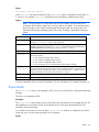
Supported firmware revisions
After February 19, 2013, all IO Accelerators will ship with firmware version 7.1.13.109322 or higher. This
firmware version only works with VSL 3.2.2 or higher. If you are installing a recently purchased or a
replacement IO Accelerator into a system that already has IO Accelerators installed, then you must upgrade
the firmware on the previously installed devices to 7.1.13.109322 or higher. The VSL must be upgraded to
3.2.2 or higher. Upgrading the firmware and VSL on cards that were running firmware versions 6.x.x or
Introduction
8
higher and VSL 3.x.x or higher is NOT data destructive. However, HP recommends that you back up any
data on the device prior to performing the upgrade. For more information on the latest supported version of
the firmware and VSL, see the HP website (http://www.hp.com).
VMware ESX version
IO Accelerator
software
IO Accelerator firmware
Comments
VMware ESX 4.0
2.2.3 or 2.3.1
101583_6 or 101971_6
(2.3.1)
Update 1; 101583 is
compatible with both software
versions.
VMware ESXi 4.0
Not supported
Not supported
ESXi 4.0 is not supported.
VMware ESX 4.1
2.2.3 or 2.3.1
101583_6 or 101971_6
(2.3.1)
Version 101583 is
compatible with both software
versions.
VMware ESXi 4.1
2.3.1
101583_6 or 101971_6
(2.3.1)
HP recommends 101971_6
firmware.
VMware ESXi 4.x
3.2.3
VMware ESXi 5.1
3.2.3
ioaccelerator_3.2.3-201301 —
22.fff
ioaccelerator_3.2.3-201301 —
22.fff
NOTE: HP StorageWorks IO Accelerators require firmware version 101971_6 or 101583. HP
PCIe IO Accelerators also support firmware version 101971_4.
Supported hardware
HP IO Accelerator for BladeSystem c-Class
BladeSystem c-Class IO Accelerators have two distinct designs for the respective server product lines. The G1
through G7 IO Accelerator adapter is provided in a c-Class Type 1 Mezzanine card form factor. It can be
installed in both Type 1 and Type 2 mezzanine slots within the c-Class blade G1 through G7 servers,
enabling a total of two cards in a half-height server blade, and three cards in a full-height server blade and
up to 6 in a double-high, double-wide server (BL680c).
The Gen8 adapter is provided in a c-Class Type B Mezzanine card form factor. It can only be installed in
Type B mezzanine slots within the Gen 8 or later servers, enabling one IO Accelerator in a half-height Gen8
server.
The Type I mezz card and the Type B mezz card are distinguished by the mezzanine connector. The type B
card is slightly larger than a Type I mezz card.
The amount of free RAM required by the driver depends on the size of the blocks used when writing to the
drive. The smaller the blocks, the more RAM is required. The table below lists the guidelines for each 80GB
of storage. For the latest information, see the QuickSpecs sheet to the HP IO Accelerator for HP BladeSystem
c-Class at HP Customer Support (http://www.hp.com/support).
The Remote Power Cut Module for the c-Class blade mezzanine card provides a higher level of protection in
the event of a catastrophic power loss (for example, a user accidentally pulls the wrong server blade out of
the slot). The Remote Power Cut Module ensures in-flight writes are completed to NAND flash in these
catastrophic scenarios. Without the Remote Power Cut Module, write performance is slower. Writes are not
acknowledged until the data is written to the NAND module, thereby slowing performance. When the
Remote Power Cut Module is installed, writes are acknowledged by the IO Accelerator controller to the
driver. The IO Accelerator controller then completes the write to the NAND module.
Introduction
9
The IO Accelerators (QK761A, QK762A, and QK763A) for Gen 8 BladeSystem c-Class have the power cut
functionality embedded on the card. They offer the protection without requiring the remote power cut module.
NOTE: The Remote Power Cut Module is used only in the AJ878B and BK836A models. Without
the Remote Power Cut Module, write performance is slower.
HP PCIe IO Accelerator minimum requirements
•
An open PCI-Express slot—The accelerator requires a minimum of one half-length, half-height slot with
a x4 physical connector. All four lanes must be connected for full performance. HP PCIe IO Accelerator
Duo requires a minimum of a full-height, half-length slot with an x8 physical connection. If your system
is using PCI 1.1, all x8 signaling lanes must be connected for full performance. If your system is using
PCI 2.0, for full performance you only have to connect x4 signaling lanes.
NOTE: For PCIe IO Accelerators, using PCIe slots greater than x4 does not improve
performance.
NOTE: The power cut feature is built into PCIe IO Accelerators; therefore, no Remote Power Cut
Module is necessary.
•
300 LFM of airflow at no greater than 50°C. To protect against thermal damage, the IO Accelerator
also monitors the junction temperature of its controller. The temperature represents the internal
temperature of the controller, and it is reported in fio-status report. The IO Accelerator begins
throttling write performance when the junction temperature reaches 78°C. If the junction temperature
continues to rise, the IO Accelerator shuts down when the temperature reaches 85°C.
NOTE: If you experience write performance throttling due to high temperatures, see your
computer documentation for details on increasing airflow, including fan speeds.
•
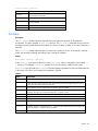
Sufficient RAM to operate—The amount of RAM that the driver requires to manage the NAND flash
varies according to the block size you select when formatting the device (filesystem format, not low-level
format). For a virtual machine using an IO Accelerator directly (using PCI pass-through), consult the user
guide for the installed operating system. The following table lists the amount of RAM required per
100GB of storage space, using various block sizes. The amount of RAM used in driver version 3.0 is
significantly less than the amount used in version 1.2.x.
Average block size
(bytes)
RAM usage for each 80
GB IO Accelerator
(Megabytes)
RAM usage for each 100 Minimum system RAM
requirement for 320 GB
GB IO Accelerator
MezzIO Accelerator*
(Megabytes)
8,192
250
280
1 GB
4,096
400
530
1.6 GB
2,048
750
1,030
3 GB
1,024
1,450
2,000
5.8 GB
512
2,850
3,970
11.4 GB
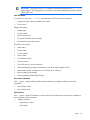
Average block size
(bytes)
Minimum system RAM
Minimum system RAM
Minimum system RAM
requirement for 640 GB requirement for 785 GB requirement for 1.2 TB
MezzIO Accelerator*
MezzIO Accelerator*
MezzIO Accelerator*
8,192
2 GB
2.2 GB
3.4 GB
4,096
3.2 GB
4.2 GB
6.4 GB
2,048
6 GB
8.1 GB
12.4 GB
1,024
11.6 GB
15.7 GB
24 GB
Introduction
10
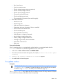
Average block size
(bytes)
Minimum system RAM
Minimum system RAM
Minimum system RAM
requirement for 640 GB requirement for 785 GB requirement for 1.2 TB
MezzIO Accelerator*
MezzIO Accelerator*
MezzIO Accelerator*
512
22.8 GB
31.2 GB
47.6 GB
* For IO Accelerator use only. Additional RAM is needed for system operating system and applications.
HP PCIe IO Accelerator Duo requirements
In addition to the IO Accelerator cooling and RAM requirements listed in the previous table, the IO
Accelerator Duo requires at least:
•
A PCIe Gen1 x8 slot or a PCIe Gen2 x4 slot
•
A minimum of a full-height, half-length slot with a x8 physical connection. For systems with PCI 1.1, all
eight signaling lanes must be active for full IO Accelerator Duo performance. For systems with PCIe 2.0,
only four signaling lanes must be active for full performance.
NOTE: With driver version 3.1.0 and later, the driver detects in the BIOS if the PCIe slot supports
a 75W power draw. If the slot supports up to 75W, the IO Accelerator device draws up to that
amount of power. However, if an external power cable is used, power is only supplied by that
cable.
To verify whether a slot is supplying 75W, view the system logs or use the fio-pci-check
utility.
Before you begin
Before installing the IO Accelerator driver, be sure you have properly installed the IO Accelerator devices.
For more information, see the hardware installation instructions that came with your IO Accelerator.
After you install this version of the IO Accelerator driver, you might have to upgrade the firmware to enable
operation. For more information, see "Upgrading firmware ("Upgrading the firmware using ESX" on page
16)."
IO Accelerators cannot be installed as part of an ESX or ESXi installation.
Introduction
11
Software installation
VMDirectPathIO
The VSL software is only required for ESX or ESXi if you plan to use the IO Accelerator device as a VMFS
datastore. If you are passing the devices through using VMDirectPathIO, you do not need to install the VSL
on your the ESX or ESXi system. Instead, install the VSL on the guest system. For example, pass the device
through to a Windows VM, and then install the Windows VSL on that VM. For installation and user
instructions, see the HP IO Accelerator for Windows User Guide.
When passing through an IO Accelerator device, you must be aware of certain constraints. For more
information, see "Working with IO Accelerators and VMDirectPathIO (on page 42)."
Command-line installation
To install and manage the VSL driver, you must use a CLI.
ESX command-line installation
ESX includes the COS. The CLI is available on the host or through an SSH connection.
ESXi command line installation
HP recommends installing VMware vCLI for your ESXi system. Install a vCLI package on a physical machine
running on a Linux or Windows operating system. For more information on VMware vCLI, see the VMware
website (http://www.vmware.com/support/developer/vcli/). HP does not recommend using the vCLI on a
virtual machine that is hosted on your ESXi system. The IO Accelerator installation and configuration
processes involve putting the ESXi host into maintenance mode and rebooting the host.
When installing the VSL, you can choose to use the TSM, also known as Shell or SSH (when used remotely),
instead of the vCLI. The TSM might be required for managing or troubleshooting your device with the
command-line utilities.
CAUTION: To avoid damage to the system, VMware recommends using TSM only for the
purposes of troubleshooting and remediation. VMware recommends using the vCLI or any other
VMware Administration Automation Product to perform routine ESXi host configuration tasks that
do not involve troubleshooting. For more information on using TSM, see the VMware Knowledge
Base article
(http://kb.vmware.com/selfservice/microsites/search.do?language=en_US&cmd=displayKC&
externalId=1017910).
Software installation 12
Installation overview
Before installing the IO Accelerator driver, make sure you have properly installed the IO Accelerator devices.
For more information, see the HP IO Accelerator Hardware Installation Guide.
1.
If necessary, uninstall previous versions of the VSL and utilities. For instructions, see "Common
maintenance tasks (on page 25)."
2.
Install the latest version of the VSL and command-line utilities.
3.
To load the driver and attach the IO Accelerator devices, reboot the ESX or ESXi system.
4.
If necessary, upgrade the firmware to the latest version.
5.
Configure the device to support VM disks.
CAUTION: The IO Accelerator device is designed to be used as a data storage disk or caching
device. HP does not support the installation of an ESX or ESXi operating system and booting from
the IO Accelerator device.
HP does not recommend labeling an IO Accelerator device as a VMware Block Device and
installing the ESX or ESXi operating system on an IO Accelerator device. If you do so, the
installation will fail when the system is rebooted.
Downloading the VMware ESXi driver
Download the installation packages to a remote machine running the vCLI.
The driver is available as an offline bundle from the HP website (http://www.hp.com/go/support).
Navigate to the appropriate folder for your operating system. Example file names:
•
iomemory-vsl_<version>.offline-bundle.zip
•
cross_vmware-esx-drivers-block-iomemory-vsl_<version>-offline-bundle.zip
The offline bundle might be in a .zip file archive:
iomemory-vsl-<version>.zip
NOTE: If the .iso image is available, it contains the same offline bundle that is available as a
standalone download. In most cases, .iso images are used to create CDs so the software can be
installed as part of an ESX installation. However, the VSL cannot be installed as part of an ESX
installation. Download the offline bundle unless you want to transfer the files to the ESX host using
a CD.
Download the following support files as appropriate for your version.
Package
Installation instructions
iodrive_<version>.fff
Upgrading the firmware
fio-remote-util-<version>.noarc Installing Python WBEM
h.rpm
packages (optional)
The fio-remote-util-<version>.noarch.rpm package is available in the Linux download folders.
Download this package from the folder for your Linux distribution (for the remote machine). For example, if
you install these remote utilities on a Linux system running RHEL 5, go to that download folder to find this
package.
Software installation 13
Transferring the VSL files to the ESX or ESXi server
You must transfer the firmware file to the ESX or ESXi host. Depending on your ESX or ESXi version and your
preferred installation method, you might also have to transfer the two bundle installation files to the host. HP
recommends transferring all the files at this point and then choosing the installation method later.
With any method that you select for transferring the files, HP recommends saving the files to a datastore on
the host. The example paths to the bundles and firmware in this guide show them located in a bundles
directory on a datastore:
/vmfs/volumes/<datastore>/bundles/
Where datastore is the name of the datastore where the files are saved.
Transfer methods
You can transfer the files using one of several methods, including:
•
vSphere Client
•
vCLI vifs command
•
SCP (using SSH)
You can copy the files to the host from your remote system or from an NFS share.
vCLI example
To transfer files to the ESX or ESXi host using vCLI:
1.
On your remote machine, be sure you have downloaded the appropriate files, and record the file
locations.
2.
Choose an available datastore with at least 200MB of available storage on the hypervisor that you will
use to temporarily store the bundles.
3.
Create a directory in the datastore named bundles using the vifs remote command:
vifs --server <servername> --mkdir "[<datastore>]bundles"
The brackets ([]) and quotes ("") are required. Substitute your datastore name for the <datastore>
variable.
IMPORTANT: When using the vCLI on a Windows operating system, many of the commands are
slightly different. Most of the commands end with .pl. Throughout this guide, when you run the
vCLI on a Windows operating system, you must add .pl to the command. For a Windows
operating systems, this command is:
vifs.pl --server <servername> --mkdir "[<datastore>]bundles"
4.
Use the following example command line to transfer each file individually to the bundles directory of the
datastore:
vifs --server <servername> --put "<path-on-local-machine>/<filename>"
"[<datastore>]bundles/<filename>"
Where <filename> is the full filename, For example:
o
o
o
iodrive_<version>.fff
cross_vmware-esx-drivers-block-iomemory-vsl_<version>.offline-bundle.z
ip
iomemory-vsl_<version>.offline-bundle.zip.
Software installation 14
Installing the VSL on ESXi 5.0
These instructions describe how to install the VSL on a single hypervisor. However, if you are familiar with the
VUM plugin for the Virtual Center Server (vCenter Server), you can use that method to install the VSL on
multiple hosts. For more details on VUM, see the vCenter Server documentation.
IMPORTANT: HP does not recommend performing an upgrade installation. Instead, uninstall the
previous version of the VSL software before you install this version. For more information on
uninstalling the software, see "Common maintenance tasks (on page 25)."
Before you install the VSL, stop all Virtual Machines and put the ESX or ESXi host into maintenance mode
using the vSphere client or the vCL.
You can choose to install the software using the vCLI or SSH. Whether you use the SSH or vCLI, you must first
transfer the files to a datastore on the ESX or ESXi host.
Installing the VSL on ESXi 5.0 using vCLI
1.
To install the bundle, run the following command against your ESXi 5.0 system using the vCLI:
esxcli --server <servername> software vib install -d <offline-bundle>
Where <offline-bundle> is the absolute path to the offline bundle on the hypervisor host. For
example, if the offline bundle is in the bundles directory of a datastore with the name of
datastore1, the local path is: /vmfs/volumes/datastore1/bundles/<offline-bundle>.
This absolute path must begin with a forward slash (/) or ESXi will return an error message.
2.
Reboot your ESXi system.
Installing the VSL on ESXi 5.0 using the command line
1.
Navigate to the directory where you have transferred the offline bundle.
2.
To install the bundle, run the following command against your ESXi 5.0 system:
esxcli software vib install -d <offline-bundle>
Where <offline-bundle> is the full name of the offline bundle that you downloaded.
The VSL and command-line utilities are installed on the host.
3.
Reboot your ESXi system.
4.
Continue to "Upgrading the firmware using ESX (on page 16)."
Installing the VSL on ESX or ESXi 4.x
IMPORTANT: HP does not recommend performing an upgrade installation. Instead, uninstall the
previous version of the VSL software before you install this version. For more information on
uninstalling the software, see "Common maintenance tasks (on page 25)."
Before you install the VSL, stop all Virtual Machines and put the ESX or ESXi host into maintenance mode
using the vSphere client or the vCL.
You can choose to install the software using the vCLI or SSH.
Software installation 15
Installing the VSL on ESX or ESXi 4.x using vCLI
IMPORTANT: Do not save the installation bundles to the ESX or ESXi 4.x host when using the
vCLI. Store them on the remote system.
1.
On your remote system, navigate to the directory that contains the downloaded files.
2.
To install the bundle, run the following command against your ESXi or ESXi 4.x system using the vCLI:
vihostupdate --server <server-name> --install --bundle
./*offline-bundle.zip
The VSL and command-line utilities are installed on the host.
3.
Reboot your ESX or ESXi system.
Installing the VSL on ESX or ESXi 4.x using the command line
You can use the COS on ESX 4.x or the TSM or SSH on ESXi 4.x to install the software. In both cases, you
must first transfer the files to the host:
1.
Navigate to the directory where you have transferred the offline bundle.
2.
To install the VSL using the offline bundle, run the esxupdate command:
$ esxupdate --bundle=<offline-bundle.zip> update
Where <offline-bundle> is the full name of the offline bundle that you downloaded.
The VSL and command-line utilities are installed on the host.
3.
Reboot the host system.
4.
Continue to "Upgrading the firmware using ESX (on page 16)."
Upgrading the firmware using ESX
After the IO Accelerator driver is loaded, ensure that the firmware is updated. To verify the update, run the
fio-status command-line utility from a supported environment.
If the output shows that the device is running in minimal mode, use the fio-update-iodrive utility in TSM
or the fio-update-iodrive.py remote script to upgrade the firmware.
If you previously installed VSL 2.x or earlier on your IO Accelerator device, you must upgrade the firmware
by following the instructions in "Upgrading device firmware from VSL 1.x.x or 2.x.x to 3.x.x (on page 17)."
When installing a new IO Accelerator device along with existing devices, it is best to upgrade all of the
devices to the latest available versions of the firmware and VSL. The latest versions are available on the HP
website (http://www.hp.com/go/support).
When using VMDirectPathIO, if you upgrade the firmware on an IO Accelerator device, you must cycle the
power for the change take place. Restarting the virtual machine won't apply the change.
CAUTION: Do not attempt to downgrade the firmware on any IO Accelerator device. Doing so
might void your warranty.
IMPORTANT: Your IO Accelerator device might have a minimum firmware label affixed (for
example, "MIN FW: XXXXXX"). This label indicates the minimum version of the firmware that is
compatible with your device.
Software installation 16
NOTE: When using PCI pass-through, if you upgrade the firmware on an IO Accelerator, you
must cycle the power for the change to take place. Restarting the virtual machine does not apply
the change.
Upgrading device firmware from VSL 1.x.x or 2.x.x to 3.x.x
CAUTION: You cannot downgrade an HP IO Accelerator device firmware to an earlier version
after you have upgraded the device.
CAUTION: Upgrading IO Accelerator devices that were previously configured for VSL 1.x.x or
2.x.x to work with VSL 3.x.x requires a low-level media format of the device. No user data is
maintained during the media format process. Be sure to backup all data on your IO Accelerator
device as instructed before upgrading the firmware.
Version 3.2.3 of the HP IO Accelerator VSL supports new features, including the latest generation of IO
Accelerator architecture and improved Flashback protection. These features require the latest version of the
firmware. Every IO Accelerator device in a system running 3.1.x or later must be upgraded to the latest
version of the firmware.
For example, if you have a system running 2.3.1 HP IO Accelerator VSL with IO Accelerator devices
previously installed, and you want to install new IO Accelerator Gen2 devices (that require the latest version
of the firmware), then you will need to upgrade all of the existing devices to the latest firmware version.
Upgrade path
Depending on the current version of your HP IO Accelerator device, to preserve the internal structure of the
device, you might have to perform multiple upgrades. The following path is the minimum upgrade path that
you must follow. Upgrade the HP IO Accelerator VSL software on the system, and upgrade the firmware to
the compatible version in the following order:
1.2.4 > 1.2.7 > 2.1.0 > 2.2.3 > 3.2.x
For VSL upgrade information for the HP IO Accelerator, see the HP IO Accelerator Release Notes on the HP
website (http://www8.hp.com/us/en/support-drivers.html). General upgrade instructions, including the
firmware update instructions, are available in the HP IO Accelerator User Guide for each operating system.
Overformatting not supported
The –o overformat option is not supported in the 3.x.x VSL software. All upgraded HP IO Accelerator
devices are formatted to the maximum advertised capacity, regardless of whether the device was
overformatted prior to the upgrade.
Upgrading procedure
Be sure to follow the upgrade path and make sure that all previously installed IO Accelerator devices are
updated with the appropriate 2.3.1-compatible firmware.
If you plan to use IO Accelerator Gen1 devices and IO Accelerator Gen2 devices in the same host, perform
this upgrade on all existing IO Accelerator Gen1 devices before installing the new IO Accelerator Gen2
devices.
1.
Prepare each existing IO Accelerator device for upgrade:
a. Backup user data on each IO Accelerator device.
Software installation 17
CAUTION: Upgrading IO Accelerator devices that were previously configured for VSL 1.x.x or
2.x.x to work with VSL 3.x.x requires a low-level media format of the device. No user data is
maintained during the media format process. Be sure to backup all data on your IO Accelerator
device as instructed before upgrading the firmware.
Do not back up the data onto another IO Accelerator device on the same system. The backup must
be to a local disk or to an externally attached volume.
b. Run the fio-bugreport command-line utility and save the output. This output captures the device
information for each device in the system. This device information will be useful in troubleshooting
any upgrade issues. For example:
fio-bugreport
2.
To uninstall the 2.3.1 HP IO Accelerator VSL software, stop all of the virtual machines and put the host
in maintenance mode. Then follow the instructions for your platform:
a. To uninstall the VSL from ESXi 5.0 using vCLI, run the following command:
esxcli --server <servername> software vib remove -n block-iomemory-vsl
b. To uninstall the VSL from ESXi 4.x using vCLI:
i.
To determine the bundle "bulletin" ID, run the following command:
vihostupdate --server <server-name> --query
Sample output:
---------Bulletin ID--------- -----Installed--------------------Summary----------------iomemory-vsl-2.2.0.7601742 2011-02-08T10:37:05
iomemory-vsl: block driver for ESXi 4.1.X
ii. To remove the "bulletin" containing the driver and utilities, run the following command:
vihostupdate --server <server-name> --remove --bulletin <Bulletin-ID>
c.
To uninstall the VSL from ESX 4.x:
i.
Enter the following command to determine the Bulletin ID of any previously installed versions:
esxupdate query
Sample output:
------Bulletin ID------ -----Installed-------------------------Summary---------------------iomemory-vsl-3.0.6.360 2012-01-16T03:49:33
iomemory-vsl: block driver for ESX/ESXi 4.X
ii. To remove installed versions, run the following command:
esxupdate -b <Bulletin-ID> remove
3.
Install the new VSL and related packages:
a. Download the VSL offline bundle and firmware from the HP website
(http://www.hp.com/go/support). For more information, see "Downloading the driver."
b. Install the VSL and utilities. Follow the instructions in "Installing the VSL on ESX or ESXi 4.x (on page
15)" or "Installing the VSL on ESXi 5.0 (on page 15)," and then return to this procedure. Be sure to
follow the suggestion to copy over the firmware file to the ESX or ESXi host, and make note of the
firmware location.
c.
Reboot the system.
Software installation 18
4.
Update the firmware on each device to the latest version using the fio-update-iodrive TSM or
COS command-line utility.
CAUTION: Do not turn off the power during a firmware upgrade, because this might cause
device failure. If a UPS is not in place, consider adding one to the system before performing a
firmware upgrade.
Sample syntax:
fio-update-iodrive <iodrive_version.fff>
Where <iodrive_version.fff> is the path to the firmware archive. This command updates all of
the devices to the selected firmware. If you wish to update specific devices, consult the utility reference
for more options.
5.
Reboot the system.
If the fio-status command is run, a warning that the upgraded devices are missing a lebmap
appears. This warning is customary, and the issue will be corrected in the next step.
CAUTION: Running the fio-format command in the next step erases the entire device,
including user data. After this format is started, the device cannot be downgraded to the 2.x
driver without voiding your warranty.
6.
Format each device using the fio-format command. For example:
fio-format <device>
You are prompted to confirm you want to erase all data on the device. The format might take an
extended period of time, depending on the amount of wear on the device.
7.
Using the following command, attach all IO Accelerator devices:
fio-attach /dev/fct*
8.
Using the following command, check the status of all devices:
fio-status -a
Your IO Accelerator devices are now successfully upgraded for this version of the HP IO Accelerator. You
can now install any IO Accelerator Gen2 devices.
Enabling PCIe power
For PCIe IO Accelerators, if you have installed any dual IO Accelerator devices, such as the HP ioDrive2
Duo, then the device might require additional power than the minimum 25 W provided by PCIe Gen2 slots
to properly function.
For instructions on enabling the device to draw additional power from the PCIe slots, see "Enabling PCIe
power override (on page 23)."
Configuring the device to support VM disks
Software installation 19
CAUTION: ESX and ESXi require 512B sector sizes. New IO Accelerator devices come
pre-formatted with 512B sector sizes from the factory. If yours is a new device, there is no need
to format it.
However, if your IO Accelerator device was previously used in a system that allowed for larger
sector sizes (such as Linux and 4KB sectors), then you must perform a format using the
fio-format utility. To prevent data loss, follow formatting instructions carefully, including
disabling and re-enabling auto attach.
Within the vSphere Client, select the Configuration tab. Under Hardware click Storage, then click Add
Storage in the top right corner. The Add Storage wizard appears. Use this wizard to configure the device.
For more information, and an explanation of options, including setting the VM file system block size, consult
your vSphere documentation.
The preferred type of virtual disk is eagerzeroedthick. HP does not recommend thin provisioning
because it degrades performance significantly.
You can now store VMs on IO Accelerator devices.
Modifying a VMware resource pool to reserve
memory
Under certain circumstances, the ESX or ESXi operating system might temporarily require all or most of the
RAM available on the system, leaving no memory for the VSL. For example, a host running VMware View
might need to rapidly provision multiple VDI images. This requirement might happen so quickly that the host
memory is temporarily exhausted.
If the VMs starve the VSL of RAM, the IO Accelerator devices might go offline or stop processing requests. To
address this issue, follow the procedure and guidelines for limiting memory consumed by the VMs.
HP recommends limiting RAM available to the VMs equal to Total Host RAM - RAM equivalent to 0.5% of the
total IO Accelerator device capacity. For more information on this calculation, see the following example
scenario. The easiest way to set this limit is by modifying the user pool.
The exact amount to limit is workload dependent and requires tuning for specific use cases.
To modify the user pool, perform the following steps using the vSphere client:
1.
Click the Summary tab in the vSphere client to view the current memory usage and capacity.
The total IO Accelerator device datastore capacity is also visible. Record the capacity.
2.
Navigate to the user Resource Allocation window:
a. Select the host > Configuration tab > Software pane > System Resource Allocation link > Advanced
link. The System Resource Pools appear.
b. Select the user node under the host tree. The details for the user appear.
c.
3.
Click the Edit settings link. The user Resource Allocation window appears.
Limit the memory allocated to the VMs:
a. Under Memory Resources, clear the Unlimited checkbox so you can set the limit for memory
resource allocation.
b. Set the limit on VM memory consumption.
Example scenario:
Software installation 20
An ESXi host has the following:
•
Memory capacity of 36,852 MB
•
Total IO Accelerator device datastore capacity of 320 GB (or approximately 320,000 MB).
320,000 MB device capacity * 0.5% of device capacity approximately 1600 MB of RAM equivalent.
36,852 MB total memory capacity - 1600 MB free = 35,252 MB of memory limited to the host.
The new value under Limit in Memory Resources is 35,252 MB.
Using the IO Accelerator as swap with ESX
The IO Accelerator cannot be used as a swap device for the ESX or ESXi host.
However, the IO Accelerator can be used as swap for virtual machines. To use the IO Accelerator as swap
for a virtual machine:
1.
Go to VMware vSphere Client > Configuration > Virtual Machine Swapfile Location.
2.
Indicate the appropriate Datastore location as the virtual machine swapfile location.
Software installation 21
Maintenance
Maintenance tools
The IO Accelerator includes both software utilities to maintain the device and external LED indicators to
display the status. You can also install SNMP as a monitoring option.
The following are the most common tasks for maintaining your IO Accelerator. You can also use the IO
Accelerator Management Tool application to perform firmware upgrades. For more information, see the HP
IO Accelerator Management Tool User Guide.
Management utilities for ESXi
Use COS/Shell/TSM command-line utilities to manage the VSL. These utilities are installed with the VSL
software. To use these utilities on ESXi, the Shell/TSM must be enabled.
For more information about these utilities, see "Command-line utilities for Tech Support Mode (on page 22)."
Command-line utilities for Tech Support Mode
Several command-line utilities are included in the installation packages. These command-line utilities are only
accessible through the VMware TSM, also known as SSH, in ESXi or COS in ESX.
IMPORTANT: VMware suggests that TSM only be used for the purposes of troubleshooting and
remediation. VMware recommends using the vSphere Client or any other VMware Administration
Automation Product to perform routine ESXi host configuration tasks that do not involve a
troubleshooting scenario. For more information on using TSM, see the VMware Knowledge Base
article
(http://kb.vmware.com/selfservice/microsites/search.do?language=en_US&cmd=displayKC&
externalId=1003677).
The IO Accelerator installation packages include various command-line utilities, installed by default to the
/usr/bin directory. These CLIs provide ways to access, test, and manipulate your device.
The following are the command-line utilities available in TSM or COS.
Command line
utility
Purpose
fio-attach (on page Makes an IO Accelerator available to the operating
system
29)
Lights the IO Accelerator external LEDs
fio-beacon (on
page 30)
fio-bugreport
Prepares a detailed report for use in troubleshooting
problems
fio-detach (on page Temporarily makes the IO Accelerator unavailable to the
operating system
32)
Maintenance
22
Command line
utility
Purpose
fio-format (on page Used to perform a low-level format of an IO Accelerator
32)
fio-pci-check (ESX Checks for errors on the PCI bus tree, specifically for PCIe
IO Accelerator devices. This utility is only supported on
only)
ESX.
fio-status (on page
34)
Displays information about the device
fio-update-iodrive
(on page 36)
Updates the IO Accelerator firmware
For more information on command-line utilities, see "Utilities (on page 29)."
Enabling PCIe power override
For PCIe IO Accelerators, if you have installed any dual IO Accelerator devices, such as the HP ioDrive2
Duo, then the device might require additional power than the minimum 25 W provided by PCIe Gen2 slots
to properly function. Even if additional power is not required for your device, all dual IO Accelerator devices
that receive additional power might benefit with improved performance.
HP ioDrive2 Duo devices must have additional power to properly function. For more information on which
devices require additional power, see the HP PCIe IO Accelerator for ProLiant Servers Installation Guide.
Additional power can be provided in two ways:
•
External power cable—This cable ships with all dual ioMemory devices. For information on installing
this cable, see the HP PCIe IO Accelerator for ProLiant Servers Installation Guide.
NOTE: When a power cable is used, all of the power is drawn from the cable and no power is
drawn from the PCIe slot.
•
Enabling full slot power draw—Some PCIe slots provide additional power (often up to 75 W of power).
If your PCIe slot is rated to provide at least 55 W, then you can allow the device to draw full power from
the PCIe slot by setting a VSL module parameter. For more information on enabling this override
parameter, see "Enabling the override parameter."
CAUTION: If the PCIe slot is not capable of providing the needed amount of power, then
enabling full power draw from the PCIe slot might result in malfunction or even damage to server
hardware. The user is responsible for any damage to equipment due to improper use of the
override parameter. HP expressly disclaims any liability for damage arising from improper use of
the override parameter. To confirm the power limits and capabilities of each slot, as well as the
entire system, contact the server manufacturer. For information about using the override
parameter, contact HP Customer Support.
NOTE: The override parameter overrides the setting that prevents devices from drawing more
than 25 W from the PCIe slot. The parameter is enabled by device using the device serial
numbers. Once the setting is overridden, each device might draw up to the full 55 W needed for
peak performance.
Before you enable the override parameter, ensure that each PCIe slot is rated to provide enough power
for all slots, devices, and server accessories. To determine the power slot limits, consult the server
documentation, BIOS interface, setup utility, or use the fio-pci-check command.
Maintenance
23
Important considerations
•
If you are installing more than one dual IO Accelerator device and enabling the override parameter for
each device, be sure the motherboard is rated to provide 55W power to each slot used. For example,
some motherboards safely provide up to 75W to any one slot, but run into power constraints when
multiple slots are used to provide that much power. Installing multiple devices in this situation might
result in server hardware damage. Consult with the manufacturer to determine the total PCIe slot power
available.
•
The override parameter persists in the system and enables full power draw on an enabled device even
if the device is removed and then placed in a different slot within the same system. If the device is placed
in a slot that is not rated to provide 55W of power, your server hardware could experience a power
drag.
•
The override parameter is a setting for the IO Accelerator VSL software by server and is not stored in the
device. When moved to a new server, the device defaults to the 25 W power limit until an external
power cable is added or the override parameter is enabled for that device in the new server. To
determine the total PCIe slot power available for the new server, consult the manufacturer.
Enabling the override parameter
1.
Use one of the following methods to determine the serial number of each device to be installed in a
compatible slot.
o
Enter the fio-status command.
Sample output:
fio-status
...
Adapter: Dual Controller Adapter
Fusion-io ioDrive2 DUO 2.41TB, Product Number:F01-001-2T41-CS-0001, FIO
SN:1149D0969
External Power: NOT connected
PCIe Power limit threshold: 24.75W
Connected ioMemory modules:
fct2: SN:1149D0969-1121
fct3: SN:1149D0969-1111
In this example, 1149D0969 is the adapter serial number.
If you have multiple IO Accelerator devices installed on your system, use the fio-beacon
command to verify where each device is physically located.
o
2.
Inspect the adapter serial number labels on the IO Accelerator devices to determine the serial
numbers. However, HP recommends confirming that each serial number is an adapter serial number
by running the fio-status command. The adapter serial number label resides on the back of all
HP ioDrive Duo devices and HP ioDrive2 Duo devices. On ioDrive Duos, the serial number is
located on the PCB component that is attached to the PCIe connector.
Set the module parameter using the esxcfg-module command. For example:
esxcfg-module --server <server-name> iomemory-vsl -s
'external_power_override=<value>'
Where the <value> for this parameter is a comma-separated list of adapter serial numbers. For
example:
Maintenance
24
1149D0969,1159E0972,24589
NOTE: The remote option (--server) is only required for the vCLI.
3.
Reboot the system to enable the parameter.
Common maintenance tasks
In ESX, these tasks require the COS. In ESXi, some of these maintenance tasks are only accessible through
VMware TSM, also known as SSH.
IMPORTANT: VMware suggests that TSM only be used for the purposes of troubleshooting and
remediation. VMware recommends using the vSphere Client or any other VMware Administration
Automation Product to perform routine ESXi host configuration tasks that do not involve a
troubleshooting scenario. For more information on using TSM, see the VMware Knowledge Base
article
(http://kb.vmware.com/selfservice/microsites/search.do?language=en_US&cmd=displayKC&
externalId=1003677).
Disabling the driver
By default, the driver automatically loads when the operating system starts. VMware ESX and ESXi do not
allow a driver to be unloaded, so you must disable driver auto-load for diagnostic or troubleshooting
purposes. For ESXi, you must run the commands in TSM.
1.
To disable driver auto-load, run the following command in TSM or COS:
$ esxcfg-module -d iomemory-vsl
2.
For ESX 4.x, you must also run the following command:
$ esxcfg-boot -b
3.
Reboot the system.
Disabling driver auto-load prevents the IO Accelerator driver from loading so the device is not available to
users. However, all other services and applications are still available.
Enabling the driver
To enable the IO Accelerator driver after maintenance, run the following commands, and then restart the
system. For ESXi, run the commands in Tech Support Mode.
1.
To enable the driver, run the following command:
$ esxcfg-module -e iomemory-vsl
2.
For ESX 4.x, you must also run the following command:
$ esxcfg-boot -b
3.
Reboot the system.
If the driver is enabled, then it appears in the modules listed when you run the following command:
$ esxcfg-module --query
Maintenance
25
Disabling auto attach
When the IO Accelerator driver is installed, it is configured to automatically attach any devices when the
driver is loaded. When necessary, disable the auto attach feature.
To disable auto attach using ESX:
1.
To set the auto_attach parameter to 0, run the following command:
esxcfg-module -s 'auto_attach=0' iomemory-vsl
2.
Restart the system.
To disable auto attach using ESXi:
1.
To set the auto_attach parameter to 0, run the following vCLI command:
$ vicfg-module --server <server-name> iomemory-vsl -s 'auto_attach=0'
2.
Restart the system.
Enabling auto attach
To enable auto attach using ESX:
1.
To set the auto_attach parameter to 1, run the following command:
# esxcfg-module -s 'auto_attach=1' iomemory-vsl
2.
Restart the system.
To enable auto attach using ESXi:
1.
To set the auto_attach parameter to 1, run the following vCLI command:
$ vicfg-module --server <server-name> iomemory-vsl -s 'auto_attach=1'
2.
Restart the system.
Uninstalling the IO Accelerator driver package
Uninstalling the software in ESX 4.x
1.
To find the ioMemory VSL Bulletin ID, run the following command:
$ esxupdate query
Sample output:
------Bulletin ID------ -----Installed-----
---------------------Summary----------------------
iomemory-vsl-3.0.6.360 2012-01-16T03:49:33 iomemory-vsl: block driver
for ESX/ESXi 4.X
2.
Run the following command to remove VSL using its Bulletin ID:
$ esxupdate -b <Bulletin-ID> remove
To uninstall the IO Accelerator driver package and command-line utilities run the following command:
$ rpm -e fio-util
Uninstalling the software in ESXi 4.x
To uninstall the VSL package, follow this procedure using the vCLI from a remote system:
1.
To determine the bundle bulletin name, run the following command:
Maintenance
26
vihostupdate --server <server-name> --query
Sample output:
---------Bulletin ID--------iomemory-vsl-2.2.0.7601742
-----Installed----2011-02-08T10:37:05
----------------Summary-----------------
iomemory-vsl: block driver for ESXi 4.1.X
2.
To remove the bulletin containing the driver and utilities, run the following command:
vihostupdate --server <server-name> --remove --bulletin
iomemory-vsl-2.2.0.7601742
Uninstalling the software in ESXi 5.0
To uninstall the VSL package, follow this procedure using the vCLI from a remote system. To remove the VIB
containing the driver and utilities, run the following command:
esxcli --server <servername> software vib remove -n block-iomemory-vsl
Unmanaged shutdown issues
Unmanaged shutdowns, due to power loss or other circumstances, force the IO Accelerator to perform a
consistency check during the reboot. This reboot might take several minutes or more to complete and is
indicated by a progress percentage during a startup.
You can cancel this consistency check by pressing Esc during the first 15 seconds after the Fusion-io
Consistency Check message appears at the prompt. However, if you choose to cancel the check, the IO
Accelerators remains unavailable to users until the check is completed. You can perform this check later using
the IO Accelerator Management Tool Attach function.
Although data written to the IO Accelerator is not lost due to unmanaged shutdowns, important data
structures might not have been properly committed to the drive. This consistency check repairs these data
structures.
Maintenance
27
Performance and tuning
Introduction to performance and tuning
HP IO Accelerator devices provide high bandwidth and high IOPS and are specifically designed to achieve
low latency.
As IO Accelerator devices improve in IOPS and low latency, the device performance may be limited by
operating system settings and BIOS configuration. To take advantage of the revolutionary performance of IO
Accelerator devices, you might have to tune these settings.
While IO Accelerator devices generally perform well out of the box, this section describes some of the
common areas where tuning may help achieve optimal performance.
Disabling DVFS
DVFS is a power management technique that adjusts the CPU voltage and frequency to reduce power
consumption by the CPU. These techniques help conserve power and reduce the heat generated by the CPU,
but they adversely affect performance while the CPU transitions between low-power and high-performance
states.
These power-savings techniques are known to have a negative impact on I/O latency and maximum IOPS.
When tuning for maximum performance, you might benefit from reducing or disabling DVSF completely,
even though this might increase power consumption.
DVFS, if available, should be configurable as part of your operating systems power management features as
well as within your system BIOS interface. Within the operating system and BIOS, DVFS features are often
found under the ACPI sections. Consult your computer documentation for details.
Limiting APCI C-states
Newer processors have the ability to go into lower power modes when they are not fully utilized. These idle
states are known as ACPI C-states. The C0 state is the normal, full power, operating state. Higher C-states
(C1, C2, C3, and so on) are lower power states.
While ACPI C-states save on power, they are known to have a negative impact on I/O latency and maximum
IOPS. With each higher C-state, typically more processor functions are limited to save power, and it takes
time to restore the processor to the C0 state.
These power savings techniques are known to have a negative impact on I/O latency and maximum IOPS.
When tuning for maximum performance you might benefit from limiting the C-states or turning them off
completely, even though this might increase power consumption.
If your processor has ACPI C-states available, you can typically limit or disable them in the BIOS interface
(sometimes referred to as a Setup Utility). APCI C-states might be part of the ACPI menu. For details, see your
computer documentation.
Performance and tuning 28
Utilities
Utilities reference
These command-line utilities are only accessible through VMware TSM, also known as SSH, on ESXi and the
COS on ESX.
IMPORTANT: VMware suggests that TSM only be used for the purposes of troubleshooting and
remediation. VMware recommends using the vSphere Client or any other VMware Administration
Automation Product to perform routine ESXi host configuration tasks that do not involve a
troubleshooting scenario. For more information on using TSM, see the VMware Knowledge Base
article
(http://kb.vmware.com/selfservice/microsites/search.do?language=en_US&cmd=displayKC&
externalId=1003677).
The VSL installation packages include various command-line utilities, installed by default to /usr/bin.
These utilities provide a number of useful ways to access, test, and manipulate your device.
Utility
Purpose
fio-attach
Makes an IO Accelerator available to the operating
system
fio-beacon
Lights the IO Accelerator external LEDs
fio-bugreport
Prepares a detailed report for use in troubleshooting
problems
fio-detach
Makes an IO Accelerator unavailable to the operating
system
fio-format
Used to perform a low-level format of an IO Accelerator
fio-pci-check
Checks for errors on the PCI bus tree, specifically for PCIe
IO Accelerator devices. This utility is only supported on
ESX.
fio-status
Displays information about the device
fio-update-iodrive
Updates the IO Accelerator firmware
NOTE: All utilities have –h (Help) and –v (Version) options.
fio-attach
The fio-attach utility requires the IO Accelerator driver to be loaded with auto-attach disabled. For more
information, see "Disabling auto attach (on page 26)."
Description
Attaches the IO Accelerator and makes it available to the operating system. This creates a block device in
/dev/fio. You can then add it to ESX as a storage area. The command displays a progress bar and
percentage as it operates.
Utilities 29
NOTE: If multiple IO Accelerator devices are installed in a computer, they attach in parallel.
Syntax
fio-attach <device> [options]
Where <device> is the name of the device node (/dev/fctx), where x indicates the card number: 0, 1,
2, and so on. For example, /dev/fct0 indicates the first IO Accelerator installed on the system.
Options
Option
Description
-c
Attach only if clean.
-q
Quiet: disables the display of the progress bar and
percentage.
In most cases, the IO Accelerator driver automatically attaches the device on load. If you need to detach the
device, run the fio-detach command. For more information, see "fio-detach (on page 32)."
fio-beacon
Description
The fio-beacon utility turns on all three LEDs of the specified IO Accelerator for identification. This utility
is not applicable for the mezzanine format of the IO Accelerator, which has no externally visible LEDs. You
must detach the IO Accelerator, and then run the fio-beacon command. For more information, see
"fio-detach (on page 32)."
Syntax
fio-beacon <device> [options]
Where <device> is the name of the device node (/dev/fctx), where x indicates the card number: 0, 1,
2, and so on. For example, /dev/fct0 indicates the first IO Accelerator installed on the system.
Options
Option
Description
-0
Off: Turns off the three LEDs
-1
On (default): Lights the three LEDs
-p
Prints the PCI bus ID of the device at <device> to standard output. Usage and error
information might be written to standard output rather than to standard error.
fio-bugreport
Description
Prepares a detailed report of the device for use in troubleshooting issues.
This utility captures the current state of the device. When a performance or stability problem occurs with the
device, run the fio-bugreport utility and contact HP support (http://www.hp.com/support) for
assistance in troubleshooting.
The output will indicate where the bugreport is saved.
Utilities 30
NOTE: If the utility recommends that you contact Fusion-io support, disregard that message and
contact HP support (http://www.hp.com/support) instead.
Syntax
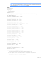
fio-bugreport
Sample output
~ # fio-bugreport
VMkernel-4.1.0
Report output: /var/tmp/fio-bugreport-20111006.223733-sc07HE.tar.gz
OS: VMware-ESX-4.1.0
Collecting esxupdate query... done
Collecting dc-status -v... done
Collecting dc-status -fk... done
Collecting fio-status -a... done
Collecting fio-status -fj... done
Collecting fio-status -fj -P/dev/stdout... done
Collecting vmkload_mod -l... done
Collecting esxcfg-module -l... done
Collecting esxcfg-scsidevs -l... done
Collecting esxcfg-scsidevs -c... done
Collecting esxcfg-scsidevs -u... done
Collecting esxcfg-scsidevs -m... done
Collecting esxcfg-scsidevs -a... done
Collecting esxcfg-info ... done
Collecting vm-support ... done
Collecting system file(s)... done
Collecting vib-env ... done
Collecting lspci ... done
Collecting lspci -p... done
Collecting lspci -vd... done
Collecting vmkchkdev -L... done
Collecting df -k... done
Collecting vdf ... done
Collecting cim-diagnostic.sh ... done
Building tar file...
Please attach the bugreport tar file
/var/tmp/fio-bugreport-20111006.173256-sc07HE.tar.gz
to your support case, including steps to reproduce the problem,
and upload or email to customer support.
Utilities 31
For example, the filename for a bug report file named
fio-bugreport-20111006.173256-sc07HE.tar.gz indicates the following:
•
Date (20111006)
•
Time (173256, or 17:32:56)
•
Misc. information (sc07HE.tar.gz)
fio-detach
CAUTION: Before using this utility, be sure that the IO Accelerator to be detached is not currently
mounted or otherwise in use (for example, as a datastore). The driver cannot determine whether
the drive is in use at the time of detaching. Detaching a drive while it is in use might cause errors,
data loss, and corruption.
The fio-detach utility detaches the IO Accelerator from the operating system one device at a time. By
default, the command displays a progress bar and percentage as it completes the process.
Syntax
fio-detach <device> [options]
where <device> is the name of the device node (/dev/fctx), where x indicates the card number: 0, 1,
2, and so on. For example, /dev/fct0 indicates the first IO Accelerator installed on the system.
Options
Option
Description
-i
Immediate: Causes a forced, immediate detach (does not save metadata). This command
will fail if the device is in use by the operating system.
-q
Quiet: Disables the display of the progress bar and percentage.
With version 2.0 and later of the driver, attempting to detach an IO Accelerator might fail with an error
indicating that the device is busy. This error typically might occur if the IO Accelerator is in use by VM or
other process, or some process has the device open.
fio-format
You must detach the IO Accelerator before running this command. For more information, see "fio-detach (on
page 32)."
Description
The fio-format command performs a low-level format of the IO Accelerator. This format is different from
a format performed by the operating system. The utility displays a progress bar and percentage as it
completes the format.
The IO Accelerator ships pre-formatted, so you only have to run the fio-format command if you need to
change the logical size of the device.
CAUTION: Use this utility with care since it deletes all user information on the IO Accelerator.
NOTE: VMFS, the default filesystem employed by ESX, requires a 512-byte sector size.
Utilities 32
Syntax
fio-format [options] <device>
where <device> is the name of the device node (/dev/fctx), where x indicates the card number: 0, 1,
2, and so on. For example, /dev/fct0 indicates the first IO Accelerator installed on the system.
Options
NOTE: ESX only supports 512 byte sector sizes for use in VMDKs. Do not format your IO
Accelerator device with any other sector size if you plan to use VMDKs. If you are passing the
device through to a VM using PCI pass-through, then the guest VM can use any sector size
appropriate for the guest operating system. In this case, formatting is performed on the guest
system.
Option
Description
-b <size B|K>
Sets the block (sector) size, in bytes or KiBytes (base 2). The default is 512 bytes. For
example: -b 512B or -b 4K (B in 512B is optional).
-f
-q
-s <size
B|K|M|G|T|%>
-o <size
B|K|M|G|T|%>
-r
-y
Forces the format size, bypassing normal checks and warnings. This option might be
needed in rare situations when the fio-format command does not proceed properly.
(The Are you sure? prompt still appears unless you use the -y option.)
Quiet mode: Disables the display of the progress-percentage indicator.
Sets the device capacity as a specific size (in TB, GB, or MB) or as a percentage of the
advertised capacity:
•
•
•
•
T—The number of terabytes (TB) to format
G—The number of gigabytes (GB) to format
M—The number of megabytes (MB) to format
%—The percentage, such as 70% (the percent sign must be included)
Over-formats the device size to greater than the advertised capacity, where the maximum
size equals the maximum physical capacity. If a percentage is used, it corresponds to the
maximum physical capacity of the device. Size is required for the -o option. For size
indicator descriptions, see the previously described -s option.
Enables fast rescan on unclean shutdowns at the cost of some capacity.
Auto-answers yes to all queries from the application, bypassing prompts.
You must re-attach the driver to use the IO Accelerator. For more information, see "fio-attach (on page 29)."
fio-pci-check
The fio-pci-check utility is only supported on ESX. If you run it on an ESXi host, it will print the following
message:
This utility is not supported on ESXi.
Description
The fio-pci-check utility checks for errors on the PCI bus tree, specifically for IO Accelerator devices. This
utility displays the current status of each IO Accelerator device. It also prints the standard PCIe error
information and resets the state.
It is normal to see as many as five errors when fio-pci-check is initially run. Subsequent runs should
reveal only one or two errors during several hours of operation.
Syntax
Utilities 33
fio-pci-check [options]
Options
Description
-d <value>
1 = Disable the link; 0 = bring the link up (HP does not
recommend this parameter)
-f
Scan every device in the system.
-i
Print the device serial number. This option is invalid when
the VSL is loaded.
-r
Force the link to retrain.
-v
Verbose: Print extra data about the hardware.
fio-status
Description
The fio-status command provides detailed information about the specified or all installed IO
Accelerators. This utility operates on /dev/fctx devices. The fio-status command must run with root
privileges and requires that the driver be loaded. If no driver is loaded, a smaller set of status information is
returned.
The fio-status command provides alerts for certain error modes, such as a minimal-mode, read-only
mode, and write-reduced mode, describing what is causing the condition.
Syntax
fio-status <device> [options]
where <device> is the name of the device node (/dev/fctx), where x indicates the card number: 0, 1,
2, and so on. For example, /dev/fct0 indicates the first IO Accelerator installed on the system.
If <device> is not specified, the fio-status command displays information for all IO Accelerator devices
in the system. If the driver is not loaded, this parameter is ignored.
Options
Option
Description
-a
Reports all available information for each device.
-e
Shows all errors and warnings for each device. This option is for diagnosing issues, and it
hides other information such as format sizes.
-c
Count: Reports only the number of IO Accelerator devices installed.
-fj
Format JSON: Creates the output in JSON format.
-d
-fx
Shows basic information set plus the total amount of data read and written (lifetime data
volumes). This option is not necessary when the -a option is used.
Format XML: Creates the output in XML format.
-u
Shows unavailable fields. Only valid with -fj or -fx.
-F<field>
Prints the value for a single field (see the -l option for field names). Requires that a device be
specified. Multiple -F options can be specified.
-U
-l
Shows unavailable fields and details why the fields are unavailable. Only valid with -fj or
-fx.
Lists the fields that can be individually accessed with -F.
Utilities 34
IMPORTANT: Starting with version 3.0.0 and later, the standard formatting of the fio-status
output changed. The changing of the format affects any custom management tools that used the
output of this utility.
Basic information
If no options are used, the fio-status command reports the following basic information:
•
Number and type of devices installed in the system
•
Driver version
Adapter information
•
Adapter type
•
Product number
•
External power status
•
PCI power limit threshold (if available)
•
Connected IO Accelerator devices
Block device information:
•
Attach status
•
Product name
•
Product number
•
Serial number
•
PCIe address and slot
•
Firmware version
•
Size of the device, out of total capacity
•
Internal temperature (average and maximum, since driver load) in degrees Celsius
•
Health status: healthy, nearing wearout, write-reduced, or read-only
•
Reserve capacity (percentage)
•
Warning capacity threshold (percentage)
Data volume information
If the -d option is used, the following data volume information is reported in addition to the basic
information:
•
Physical bytes written
•
Physical bytes read
All information
If the -a option is used, all information is printed, which includes the following information in addition to
basic and data volume information:
•
Adapter information
o
Manufacturer number
o
Part number
Utilities 35
•
o
Date of manufacture
o
Power loss protection status
o
PCIe bus voltage (average, minimum, maximum)
o
PCIe bus current (average, maximum)
o
PCIe bus power (average, maximum
o
PCIe power limit threshold (watts)
o
PCIe slot available power (watts)
o
PCIe negotiated link information (lanes and throughput)
Block device information
o
Manufacturer code
o
Manufacturing date
o
Vendor and sub-vendor information
o
Format status and sector information (if device is attached)
o
FPGA ID and Low-level format GUID
o
PCIe slot available power
o
PCIe negotiated link information
o
Card temperature, in degrees Centigrade
o
Internal voltage, average and maximum
o
Auxiliary voltage, average and maximum
o
Percentage of good blocks, data and metadata
o
Lifetime data volume statistics
o
RAM usage
Error mode information
If the IO Accelerator driver is in minimal mode, read-only mode, or write-reduced mode when the
fio-status command is run, the following differences occur in the output:
•
Attach status is Status unknown: Driver is in MINIMAL MODE
•
The reason for the minimal mode state appears. (For example, Firmware is out of date. Update
firmware.)
•
Geometry and capacity information not available appears.
•
No media health information appears.
fio-update-iodrive
Description
IMPORTANT: The IO Accelerator devices must be detached before running the
fio-update-iodrive command. To detach the devices requires rebooting with auto-attach
disabled or using fio-detach. For details, see "fio-detach (on page 32)."
The fio-update-iodrive utility updates the HP IO Accelerator firmware. This utility scans the PCI-Express
bus for all HP IO Accelerators and updates them all sequentially.
Utilities 36
To ensure a clean firmware update, you must detach the device from the system using the fio-detach
utility. For more information, see "fio-detach (on page 32)."
To update one or more specific drives (rather than all drives):
•
Make sure the IO Accelerator driver is loaded.
•
Use the -d option with the device number.
CAUTION: Do not turn off the power during a firmware upgrade, because this might cause
device failure. If a UPS is not in place, consider adding one to the system before performing a
firmware upgrade.
CAUTION: When running multiple upgrades in sequence (such as going from driver version
1.2.1 to 1.2.4 to 2.2.2), you must reboot the system after each firmware upgrade step.
Otherwise the on-drive format does not change, and data loss occurs.
CAUTION: Do not use this utility to downgrade the IO Accelerator to an earlier version of the
firmware. Doing so might result in data loss. If you need to downgrade your firmware, contact HP
customer support. For more information, see "Technical support."
NOTE: If you receive an error message when updating the firmware instructing you to update the
midprom information, contact Customer Support. For more information, see "Technical support."
NOTE: If you upgrade the firmware on an IO Accelerator when using PCI pass-through, you must
cycle the power to apply the change. Restarting the VM does not apply the change.
The default action (without using the -d option) is to upgrade all IO Accelerators with the firmware contained
in the <iodrive_version.fff> file. Confirm that all devices need the upgrade prior to running the
update. If in doubt, use the -p (Pretend) option to view the possible results of the update.
Syntax
fio-update-iodrive [options] <iodrive_version.fff>
where <iodrive_version.fff> is the path and firmware archive file. You must transfer the firmware
archive file to the ESX host (this must be a local path to the host) before you run the update.
All three external LED indicators light up during the update process.
Command
Description
-d
Updates the specified devices (by fctx, where x is the
number of the device shown in fio-status). If this
option is not specified, all devices are updated.
-f
Forces upgrade. Used primarily to downgrade to an
earlier firmware version.
-l
Lists firmware available in the archive.
-p
Pretend. Shows what updates are done. The firmware is
not modified.
-c
Clears locks placed on a device.
-q
Runs the update process without displaying the progress
bar or percentage.
-y
Confirm all warning messages.
Utilities 37
CAUTION: Use the -f option with care because it might damage your board.
CAUTION: Use the {{-d}} option with care, because updating the wrong device might
damage the device.
Utilities
38
Monitoring IO Accelerator health
NAND flash and component failure
The IO Accelerator is a highly fault-tolerant storage subsystem that provides many levels of protection against
component failure and the loss nature of solid state storage. However, as in all storage subsystems,
component failures might occur.
When a large enough number of data blocks is retired due to error, the NAND flash media is considered
worn out. By properly selecting NAND flash media for the hosted application and proactively monitoring
device age and health, you can assure reliable performance over the intended product life.
Health metrics
The IO Accelerator driver manages block retirement using pre-determined retirement thresholds. The
fio-status utility show a health indicator that starts at 100 and counts down to 0. As certain thresholds
are crossed, various actions are taken.
At the 10% healthy threshold, a one-time warning is issued. For methods on capturing this alarm event, see
"Health monitoring techniques (on page 39)."
At 0%, the device is considered unhealthy. It enters write-reduced mode, which somewhat prolongs its
lifespan so data can be safely migrated. In this state, the IO Accelerator behaves normally except for the
reduced write performance.
At some point after the 0% threshold, the device enters read-only mode. Any attempt to write to the IO
Accelerator causes an error. Some file systems might require special mount options to mount a read-only
block device, beyond specifying that the mount should be read-only.
Consider the read-only mode as a final opportunity to migrate data off the device since device failure is more
likely with continued use.
The IO Accelerator might enter failure mode. In this case, the device is offline and inaccessible. Failure mode
can be caused by an internal catastrophic failure, improper firmware upgrade procedures, or device wears
out.
Health monitoring techniques
Output from the fio-status utility shows the health percentage and drive state. These items are referenced
as Media Status in the following sample output.
Found 1 ioDrive in this system
Fusion-io driver version: 2.2.3 build 240
Adapter: ioDrive
Fusion-io ioDrive 160GB, Product Number:FS1-002-161-ES
...
Media status: Healthy; Reserves: 100.00%, warn at 10.00%; Data: 99.12%
Monitoring IO Accelerator health 39
Lifetime data volumes:
Physical bytes written: 6,423,563,326,064
Physical bytes read : 5,509,006,756,312
Flashback substitution events
The IO Accelerator is equipped with Flashback substitution capability. This capability allows for predictive
NAND flash failures to occur and keep the IO Accelerator functioning by substituting out bad locations or
even a whole NAND chip. The output of the fio-status –a command will show if any flashback
substitution events have occurred.
The following is an example of the output after entering the fio-status –a command. The numbers
represent the bank (0-3) and chip number that was substituted.
First flashback event -> No action to take as infant mortality condition on NAND
chip was caught per design.
Second flashback event –> Run fio-bugreport. Return the card (if under warranty)
when you see two or more flashback substitution events.
•
Flashback active on (bank a/chip m) and (bank b/chip n)
•
Flashback active on (bank a/chip m) and (bank b/chip m) (chip failure)
(multi-bank failure)
On the second flashback event, include the output from running the fio-bugreport command when you
return the card.
Monitoring IO Accelerator health 40
Module parameters
Using module parameters
The following table describes the module parameters you can set using the esxcfg-module command.
The remote option (--server) is only required for the vCLI.
Sample command:
esxcfg-module --server <server-name> iomemory-vsl -s '<parameter>=<value>'
You must reboot the ESX or ESXi system to enforce any parameter changes.
Module parameter
Default (min/max)
Description
auto_attach
1
1 = Always attach the device on startup.
0 = Do not attach the device on startup.
external_power_override*
No devices selected
Allows selected devices to draw full power from
the PCIe slot. The <value> for this parameter is
a comma-separated list of adapter serial
numbers.
force_minimal_mode
0
1 = Force minimal mode on the device.
0 = Do not force minimal mode on the device.
parallel_attach
True
1 = Enable parallel attach of multiple drivers.
0 = Disable parallel attach of multiple drives.
tintr_hw_wait
0 (0, 255)
Interval (microseconds) to wait between
hardware interrupts. Also known as interrupt
coalescing.
0 = Off.
*Use this parameter with care. For more information, see "Enabling PCIe power override (on page 23)."
Except for the external_power_override parameter, module parameters apply to all IO Accelerator
devices in the system.
To query the current module parameters, use the following command:
esxcfg-module --server <server-name> iomemory-vsl -g
Module parameters
41
VMDirectPathIO
Working with IO Accelerators and VMDirectPathIO
Each IO Accelerator device can either be used as a VMFS datastore in ESX or ESXi, or it can be passed
through directly to a VM. In VMware documentation, passing through to a VM this is referred to as
VMDirectPathIO.
If you are passing the devices through, you do not have to install the VSL on the ESX or ESXi system. Instead,
install the software on the guest system. Install the driver only if you plan to create a VMFS on the devices.
When using VMDirectPathIO, if you upgrade the firmware on an IO Accelerator device, you must cycle the
power to have the change take place. Restarting the VM will not apply the change.
Using products with multiple devices
Some products, such as the HP IO Accelerator ioDrive Duo, contain multiple devices. The VSL does not
support splitting the modules between two functions or VMs. The following scenarios are supported:
•
Both IO Accelerator devices are used as a VMFS datastore in ESX or ESXi.
•
Both IO Accelerator devices are passed through to the same VM using VMDirectPathIO.
VMDirectPathIO 42
Resources
Subscription service
HP recommends that you register your product at the Subscriber’s Choice for Business website
(http://www.hp.com/support).
After registering, you will receive e-mail notification of product enhancements, new driver versions, firmware
updates, and other product resources.
For more information
For additional information, see the following HP websites:
•
HP BladeSystem technical resources (http://www.hp.com/go/bladesystem/documentation) (white
papers and support documents)
•
HP BladeSystem components
(http://h18004.www1.hp.com/products/blades/components/c-class-compmatrix.html)
•
HP support (http://www.hp.com/support)
Resources
43
Support and other resources
Before you contact HP
Be sure to have the following information available before you call HP:
•
Active Health System log (HP ProLiant Gen8 or later products)
Download and have available an Active Health System log for 3 days before the failure was detected.
For more information, see the HP iLO 4 User Guide or HP Intelligent Provisioning User Guide on the HP
website (http://www.hp.com/go/ilo/docs).
•
Onboard Administrator SHOW ALL report (for HP BladeSystem products only)
For more information on obtaining the Onboard Administrator SHOW ALL report, see the HP website
(http://www.hp.com/go/OAlog).
•
Technical support registration number (if applicable)
•
Product serial number
•
Product model name and number
•
Product identification number
•
Applicable error messages
•
Add-on boards or hardware
•
Third-party hardware or software
•
Operating system type and revision level
HP contact information
For United States and worldwide contact information, see the Contact HP website
(http://www.hp.com/go/assistance).
In the United States:
•
To contact HP by phone, call 1-800-334-5144. For continuous quality improvement, calls may be
recorded or monitored.
•
If you have purchased a Care Pack (service upgrade), see the Support & Drivers website
(http://www8.hp.com/us/en/support-drivers.html). If the problem cannot be resolved at the website,
call 1-800-633-3600. For more information about Care Packs, see the HP website
(http://pro-aq-sama.houston.hp.com/services/cache/10950-0-0-225-121.html).
Customer Self Repair
HP products are designed with many Customer Self Repair (CSR) parts to minimize repair time and allow for
greater flexibility in performing defective parts replacement. If during the diagnosis period HP (or HP service
Support and other resources
44
providers or service partners) identifies that the repair can be accomplished by the use of a CSR part, HP will
ship that part directly to you for replacement. There are two categories of CSR parts:
•
Mandatory—Parts for which customer self repair is mandatory. If you request HP to replace these parts,
you will be charged for the travel and labor costs of this service.
•
Optional—Parts for which customer self repair is optional. These parts are also designed for customer
self repair. If, however, you require that HP replace them for you, there may or may not be additional
charges, depending on the type of warranty service designated for your product.
NOTE: Some HP parts are not designed for customer self repair. In order to satisfy the customer warranty,
HP requires that an authorized service provider replace the part. These parts are identified as "No" in the
Illustrated Parts Catalog.
Based on availability and where geography permits, CSR parts will be shipped for next business day
delivery. Same day or four-hour delivery may be offered at an additional charge where geography permits.
If assistance is required, you can call the HP Technical Support Center and a technician will help you over the
telephone. HP specifies in the materials shipped with a replacement CSR part whether a defective part must
be returned to HP. In cases where it is required to return the defective part to HP, you must ship the defective
part back to HP within a defined period of time, normally five (5) business days. The defective part must be
returned with the associated documentation in the provided shipping material. Failure to return the defective
part may result in HP billing you for the replacement. With a customer self repair, HP will pay all shipping
and part return costs and determine the courier/carrier to be used.
For more information about HP's Customer Self Repair program, contact your local service provider. For the
North American program, refer to the HP website (http://www.hp.com/go/selfrepair).
Réparation par le client (CSR)
Les produits HP comportent de nombreuses pièces CSR (Customer Self Repair = réparation par le client) afin
de minimiser les délais de réparation et faciliter le remplacement des pièces défectueuses. Si pendant la
période de diagnostic, HP (ou ses partenaires ou mainteneurs agréés) détermine que la réparation peut être
effectuée à l'aide d'une pièce CSR, HP vous l'envoie directement. Il existe deux catégories de pièces CSR:
Obligatoire - Pièces pour lesquelles la réparation par le client est obligatoire. Si vous demandez à HP de
remplacer ces pièces, les coûts de déplacement et main d'œuvre du service vous seront facturés.
Facultatif - Pièces pour lesquelles la réparation par le client est facultative. Ces pièces sont également
conçues pour permettre au client d'effectuer lui-même la réparation. Toutefois, si vous demandez à HP de
remplacer ces pièces, l'intervention peut ou non vous être facturée, selon le type de garantie applicable à
votre produit.
REMARQUE: Certaines pièces HP ne sont pas conçues pour permettre au client d'effectuer lui-même la
réparation. Pour que la garantie puisse s'appliquer, HP exige que le remplacement de la pièce soit effectué
par un Mainteneur Agréé. Ces pièces sont identifiées par la mention "Non" dans le Catalogue illustré.
Les pièces CSR sont livrées le jour ouvré suivant, dans la limite des stocks disponibles et selon votre situation
géographique. Si votre situation géographique le permet et que vous demandez une livraison le jour même
ou dans les 4 heures, celle-ci vous sera facturée. Pour bénéficier d'une assistance téléphonique, appelez le
Centre d'assistance technique HP. Dans les documents envoyés avec la pièce de rechange CSR, HP précise
s'il est nécessaire de lui retourner la pièce défectueuse. Si c'est le cas, vous devez le faire dans le délai
indiqué, généralement cinq (5) jours ouvrés. La pièce et sa documentation doivent être retournées dans
l'emballage fourni. Si vous ne retournez pas la pièce défectueuse, HP se réserve le droit de vous facturer les
coûts de remplacement. Dans le cas d'une pièce CSR, HP supporte l'ensemble des frais d'expédition et de
retour, et détermine la société de courses ou le transporteur à utiliser.
Support and other resources
45
Pour plus d'informations sur le programme CSR de HP, contactez votre Mainteneur Agrée local. Pour plus
d'informations sur ce programme en Amérique du Nord, consultez le site Web HP
(http://www.hp.com/go/selfrepair).
Riparazione da parte del cliente
Per abbreviare i tempi di riparazione e garantire una maggiore flessibilità nella sostituzione di parti
difettose, i prodotti HP sono realizzati con numerosi componenti che possono essere riparati direttamente
dal cliente (CSR, Customer Self Repair). Se in fase di diagnostica HP (o un centro di servizi o di assistenza
HP) identifica il guasto come riparabile mediante un ricambio CSR, HP lo spedirà direttamente al cliente per
la sostituzione. Vi sono due categorie di parti CSR:
Obbligatorie – Parti che devono essere necessariamente riparate dal cliente. Se il cliente ne affida la
riparazione ad HP, deve sostenere le spese di spedizione e di manodopera per il servizio.
Opzionali – Parti la cui riparazione da parte del cliente è facoltativa. Si tratta comunque di componenti
progettati per questo scopo. Se tuttavia il cliente ne richiede la sostituzione ad HP, potrebbe dover sostenere
spese addizionali a seconda del tipo di garanzia previsto per il prodotto.
NOTA: alcuni componenti HP non sono progettati per la riparazione da parte del cliente. Per rispettare la
garanzia, HP richiede che queste parti siano sostituite da un centro di assistenza autorizzato. Tali parti sono
identificate da un "No" nel Catalogo illustrato dei componenti.
In base alla disponibilità e alla località geografica, le parti CSR vengono spedite con consegna entro il
giorno lavorativo seguente. La consegna nel giorno stesso o entro quattro ore è offerta con un supplemento
di costo solo in alcune zone. In caso di necessità si può richiedere l'assistenza telefonica di un addetto del
centro di supporto tecnico HP. Nel materiale fornito con una parte di ricambio CSR, HP specifica se il cliente
deve restituire dei componenti. Qualora sia richiesta la resa ad HP del componente difettoso, lo si deve
spedire ad HP entro un determinato periodo di tempo, generalmente cinque (5) giorni lavorativi. Il
componente difettoso deve essere restituito con la documentazione associata nell'imballo di spedizione
fornito. La mancata restituzione del componente può comportare la fatturazione del ricambio da parte di HP.
Nel caso di riparazione da parte del cliente, HP sostiene tutte le spese di spedizione e resa e sceglie il
corriere/vettore da utilizzare.
Per ulteriori informazioni sul programma CSR di HP contattare il centro di assistenza di zona. Per il
programma in Nord America fare riferimento al sito Web HP (http://www.hp.com/go/selfrepair).
Customer Self Repair
HP Produkte enthalten viele CSR-Teile (Customer Self Repair), um Reparaturzeiten zu minimieren und höhere
Flexibilität beim Austausch defekter Bauteile zu ermöglichen. Wenn HP (oder ein HP Servicepartner) bei der
Diagnose feststellt, dass das Produkt mithilfe eines CSR-Teils repariert werden kann, sendet Ihnen HP dieses
Bauteil zum Austausch direkt zu. CSR-Teile werden in zwei Kategorien unterteilt:
Zwingend – Teile, für die das Customer Self Repair-Verfahren zwingend vorgegeben ist. Wenn Sie den
Austausch dieser Teile von HP vornehmen lassen, werden Ihnen die Anfahrt- und Arbeitskosten für diesen
Service berechnet.
Optional – Teile, für die das Customer Self Repair-Verfahren optional ist. Diese Teile sind auch für Customer
Self Repair ausgelegt. Wenn Sie jedoch den Austausch dieser Teile von HP vornehmen lassen möchten,
können bei diesem Service je nach den für Ihr Produkt vorgesehenen Garantiebedingungen zusätzliche
Kosten anfallen.
Support and other resources
46
HINWEIS: Einige Teile sind nicht für Customer Self Repair ausgelegt. Um den Garantieanspruch des
Kunden zu erfüllen, muss das Teil von einem HP Servicepartner ersetzt werden. Im illustrierten Teilekatalog
sind diese Teile mit „No“ bzw. „Nein“ gekennzeichnet.
CSR-Teile werden abhängig von der Verfügbarkeit und vom Lieferziel am folgenden Geschäftstag geliefert.
Für bestimmte Standorte ist eine Lieferung am selben Tag oder innerhalb von vier Stunden gegen einen
Aufpreis verfügbar. Wenn Sie Hilfe benötigen, können Sie das HP technische Support Center anrufen und
sich von einem Mitarbeiter per Telefon helfen lassen. Den Materialien, die mit einem CSR-Ersatzteil geliefert
werden, können Sie entnehmen, ob das defekte Teil an HP zurückgeschickt werden muss. Wenn es
erforderlich ist, das defekte Teil an HP zurückzuschicken, müssen Sie dies innerhalb eines vorgegebenen
Zeitraums tun, in der Regel innerhalb von fünf (5) Geschäftstagen. Das defekte Teil muss mit der zugehörigen
Dokumentation in der Verpackung zurückgeschickt werden, die im Lieferumfang enthalten ist. Wenn Sie das
defekte Teil nicht zurückschicken, kann HP Ihnen das Ersatzteil in Rechnung stellen. Im Falle von Customer
Self Repair kommt HP für alle Kosten für die Lieferung und Rücksendung auf und bestimmt den
Kurier-/Frachtdienst.
Weitere Informationen über das HP Customer Self Repair Programm erhalten Sie von Ihrem Servicepartner
vor Ort. Informationen über das CSR-Programm in Nordamerika finden Sie auf der HP Website unter
(http://www.hp.com/go/selfrepair).
Reparaciones del propio cliente
Los productos de HP incluyen muchos componentes que el propio usuario puede reemplazar (Customer Self
Repair, CSR) para minimizar el tiempo de reparación y ofrecer una mayor flexibilidad a la hora de realizar
sustituciones de componentes defectuosos. Si, durante la fase de diagnóstico, HP (o los proveedores o socios
de servicio de HP) identifica que una reparación puede llevarse a cabo mediante el uso de un componente
CSR, HP le enviará dicho componente directamente para que realice su sustitución. Los componentes CSR se
clasifican en dos categorías:
•
Obligatorio: componentes para los que la reparación por parte del usuario es obligatoria. Si solicita a
HP que realice la sustitución de estos componentes, tendrá que hacerse cargo de los gastos de
desplazamiento y de mano de obra de dicho servicio.
•
Opcional: componentes para los que la reparación por parte del usuario es opcional. Estos
componentes también están diseñados para que puedan ser reparados por el usuario. Sin embargo, si
precisa que HP realice su sustitución, puede o no conllevar costes adicionales, dependiendo del tipo de
servicio de garantía correspondiente al producto.
NOTA: Algunos componentes no están diseñados para que puedan ser reparados por el usuario. Para que
el usuario haga valer su garantía, HP pone como condición que un proveedor de servicios autorizado
realice la sustitución de estos componentes. Dichos componentes se identifican con la palabra "No" en el
catálogo ilustrado de componentes.
Según la disponibilidad y la situación geográfica, los componentes CSR se enviarán para que lleguen a su
destino al siguiente día laborable. Si la situación geográfica lo permite, se puede solicitar la entrega en el
mismo día o en cuatro horas con un coste adicional. Si precisa asistencia técnica, puede llamar al Centro de
asistencia técnica de HP y recibirá ayuda telefónica por parte de un técnico. Con el envío de materiales
para la sustitución de componentes CSR, HP especificará si los componentes defectuosos deberán
devolverse a HP. En aquellos casos en los que sea necesario devolver algún componente a HP, deberá
hacerlo en el periodo de tiempo especificado, normalmente cinco días laborables. Los componentes
defectuosos deberán devolverse con toda la documentación relacionada y con el embalaje de envío. Si no
enviara el componente defectuoso requerido, HP podrá cobrarle por el de sustitución. En el caso de todas
Support and other resources
47
sustituciones que lleve a cabo el cliente, HP se hará cargo de todos los gastos de envío y devolución de
componentes y escogerá la empresa de transporte que se utilice para dicho servicio.
Para obtener más información acerca del programa de Reparaciones del propio cliente de HP, póngase en
contacto con su proveedor de servicios local. Si está interesado en el programa para Norteamérica, visite
la página web de HP siguiente (http://www.hp.com/go/selfrepair).
Customer Self Repair
Veel onderdelen in HP producten zijn door de klant zelf te repareren, waardoor de reparatieduur tot een
minimum beperkt kan blijven en de flexibiliteit in het vervangen van defecte onderdelen groter is. Deze
onderdelen worden CSR-onderdelen (Customer Self Repair) genoemd. Als HP (of een HP Service Partner) bij
de diagnose vaststelt dat de reparatie kan worden uitgevoerd met een CSR-onderdeel, verzendt HP dat
onderdeel rechtstreeks naar u, zodat u het defecte onderdeel daarmee kunt vervangen. Er zijn twee
categorieën CSR-onderdelen:
Verplicht: Onderdelen waarvoor reparatie door de klant verplicht is. Als u HP verzoekt deze onderdelen
voor u te vervangen, worden u voor deze service reiskosten en arbeidsloon in rekening gebracht.
Optioneel: Onderdelen waarvoor reparatie door de klant optioneel is. Ook deze onderdelen zijn ontworpen
voor reparatie door de klant. Als u echter HP verzoekt deze onderdelen voor u te vervangen, kunnen
daarvoor extra kosten in rekening worden gebracht, afhankelijk van het type garantieservice voor het
product.
OPMERKING: Sommige HP onderdelen zijn niet ontwikkeld voor reparatie door de klant. In verband met
de garantievoorwaarden moet het onderdeel door een geautoriseerde Service Partner worden vervangen.
Deze onderdelen worden in de geïllustreerde onderdelencatalogus aangemerkt met "Nee".
Afhankelijk van de leverbaarheid en de locatie worden CSR-onderdelen verzonden voor levering op de
eerstvolgende werkdag. Levering op dezelfde dag of binnen vier uur kan tegen meerkosten worden
aangeboden, indien dit mogelijk is gezien de locatie. Indien assistentie gewenst is, belt u een HP Service
Partner om via de telefoon technische ondersteuning te ontvangen. HP vermeldt in de documentatie bij het
vervangende CSR-onderdeel of het defecte onderdeel aan HP moet worden geretourneerd. Als het defecte
onderdeel aan HP moet worden teruggezonden, moet u het defecte onderdeel binnen een bepaalde
periode, gewoonlijk vijf (5) werkdagen, retourneren aan HP. Het defecte onderdeel moet met de
bijbehorende documentatie worden geretourneerd in het meegeleverde verpakkingsmateriaal. Als u het
defecte onderdeel niet terugzendt, kan HP u voor het vervangende onderdeel kosten in rekening brengen. Bij
reparatie door de klant betaalt HP alle verzendkosten voor het vervangende en geretourneerde onderdeel en
kiest HP zelf welke koerier/transportonderneming hiervoor wordt gebruikt.
Neem contact op met een Service Partner voor meer informatie over het Customer Self Repair programma
van HP. Informatie over Service Partners vindt u op de HP website (http://www.hp.com/go/selfrepair).
Reparo feito pelo cliente
Os produtos da HP são projetados com muitas peças para reparo feito pelo cliente (CSR) de modo a
minimizar o tempo de reparo e permitir maior flexibilidade na substituição de peças com defeito. Se,
durante o período de diagnóstico, a HP (ou fornecedores/parceiros de serviço da HP) concluir que o reparo
pode ser efetuado pelo uso de uma peça CSR, a peça de reposição será enviada diretamente ao cliente.
Existem duas categorias de peças CSR:
Obrigatória – Peças cujo reparo feito pelo cliente é obrigatório. Se desejar que a HP substitua essas peças,
serão cobradas as despesas de transporte e mão-de-obra do serviço.
Support and other resources
48
Opcional – Peças cujo reparo feito pelo cliente é opcional. Essas peças também são projetadas para o
reparo feito pelo cliente. No entanto, se desejar que a HP as substitua, pode haver ou não a cobrança de
taxa adicional, dependendo do tipo de serviço de garantia destinado ao produto.
OBSERVAÇÃO: Algumas peças da HP não são projetadas para o reparo feito pelo cliente. A fim de
cumprir a garantia do cliente, a HP exige que um técnico autorizado substitua a peça. Essas peças estão
identificadas com a marca "No" (Não), no catálogo de peças ilustrado.
Conforme a disponibilidade e o local geográfico, as peças CSR serão enviadas no primeiro dia útil após o
pedido. Onde as condições geográficas permitirem, a entrega no mesmo dia ou em quatro horas pode ser
feita mediante uma taxa adicional. Se precisar de auxílio, entre em contato com o Centro de suporte técnico
da HP para que um técnico o ajude por telefone. A HP especifica nos materiais fornecidos com a peça CSR
de reposição se a peça com defeito deve ser devolvida à HP. Nos casos em que isso for necessário, é
preciso enviar a peça com defeito à HP dentro do período determinado, normalmente cinco (5) dias úteis.
A peça com defeito deve ser enviada com a documentação correspondente no material de transporte
fornecido. Caso não o faça, a HP poderá cobrar a reposição. Para as peças de reparo feito pelo cliente, a
HP paga todas as despesas de transporte e de devolução da peça e determina a transportadora/serviço
postal a ser utilizado.
Para obter mais informações sobre o programa de reparo feito pelo cliente da HP, entre em contato com o
fornecedor de serviços local. Para o programa norte-americano, visite o site da HP
(http://www.hp.com/go/selfrepair).
Support and other resources
49
Support and other resources
50
Support and other resources
51
Regulatory information
Safety and regulatory compliance
For safety, environmental, and regulatory information, see Safety and Compliance Information for Server,
Storage, Power, Networking, and Rack Products, available at the HP website
(http://www.hp.com/support/Safety-Compliance-EnterpriseProducts).
Turkey RoHS material content declaration
Ukraine RoHS material content declaration
Warranty information
HP ProLiant and X86 Servers and Options (http://www.hp.com/support/ProLiantServers-Warranties)
HP Enterprise Servers (http://www.hp.com/support/EnterpriseServers-Warranties)
HP Storage Products (http://www.hp.com/support/Storage-Warranties)
HP Networking Products (http://www.hp.com/support/Networking-Warranties)
Regulatory information 52
Acronyms and abbreviations
CIM
common information model
COS
console operating system
DVFS
dynamic voltage and frequency scaling
IOPS
input/output operations per second
LFM
linear feet per minute
NAND
Not AND
PCIe
peripheral component interconnect express
SSH
Secure Shell
TSM
technical support mode
vCLI
vSphere Command Line Interface
VIB
vSphere Installation Bundle
VM
Virtual Machine
Acronyms and abbreviations
53
VMFS
virtual machine file system
VSL
virtual storage layer
VUM
VMware Update Manager
WBEM
Web-Based Enterprise Management
Acronyms and abbreviations
54
Documentation feedback
HP is committed to providing documentation that meets your needs. To help us improve the documentation,
send any errors, suggestions, or comments to Documentation Feedback (mailto:[email protected]).
Include the document title and part number, version number, or the URL when submitting your feedback.
Documentation feedback
55
Index
A
about this guide 5
authorized reseller 44
B
battery replacement notice 52
before you begin 11
C
command-line installation 12
command-line utilities 22
configuring the device to support VM disks 19
contents summary 5
CSR (customer self repair) 44
customer self repair (CSR) 44
D
disabling auto attach 26
disabling DVFS 28
disabling the driver 25
documentation feedback 55
downloading the driver 13
E
enabling auto attach 26
Enabling PCIe power 19
enabling PCIe power override 23
enabling the driver 25
enabling the override parameter 24
ESX command-line installation 12
ESXi command-line installation 12
European Union notice 52
F
fio-attach utility 29
fio-beacon utility 30
fio-bugreport utility 30
fio-detach utility 32
fio-format utility 32
fio-pci-check utility 33
fio-status utility 34
fio-update-iodrive utility 36
flashback substitution events 40
For more information 43
H
health metrics 39
health monitoring techniques 39
HP Subscriber's Choice for Business 43
HP technical support 44
HP, contacting 44
I
installation overview 7, 8, 11, 12, 13
installing VSL files 15
installing VSL files using the command line 15, 16
installing VSL files using vCLI 15, 16
introduction 6
L
limiting APCI C-states 28
M
maintenance 22, 25, 27
maintenance tools 22
management utilities 22
modifying VMware resource pool 20
module parameters 41
monitoring IO Accelerator health 39
N
NAND flash and component failure 39
O
operating environment 8
override parameter, enabling 24
overview 6
P
PCIe power override, enabling 23
Index
56
PCIe power, enabling 19
performance and tuning 28
performance and tuning, introduction 28
performance attributes 7
phone numbers 44
product naming 6
R
regulatory compliance identification numbers 52
regulatory compliance notices 52
resources 43, 44
S
series number 52
support 44
supported firmware revisions 8
supported hardware 9
T
Taiwan battery recycling notice 52
technical support 44
telephone numbers 44
transferring VSL files 14
U
uninstalling the driver 26
unmanaged shutdown issues 27
upgrading firmware 16, 17
upgrading, procedure 17
using module parameters 41
using products with multiple devices 42
using the IO Accelerator as a swap 21
utilities 29
utilities reference 29
V
VM disks 19
VMDirectPathIO 12, 42
VMDirectPathIO, working with IO Accelerators 42
Index
57