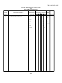
1
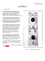
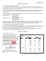
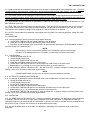
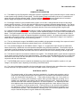
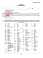
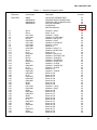
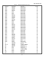
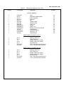
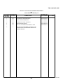
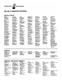
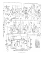
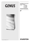
TM 11-6625-2872-14&P
TECHNICAL MANUAL
OPERATOR'S, ORGANIZATIONAL,
DIRECT SUPPORT AND GENERAL SUPPORT
MAINTENANCE MANUAL
(INCLUDING REPAIR PARTS AND SPECIAL TOOLS LIST)
FOR
PREAMPLIFIER, LOGARITHMIC
AM-6681(V)1/U
(HEWLETT-PACKARD MODEL 8808A)
(NSN 6625-00-134-3557)
HEADQUARTERS, DEPARTMENT OF THE ARMY
12 MARCH 1981
5
SAFETY STEPS TO FOLLOW IF SOMEONE IS THE VICTIM OF ELECTRICAL SHOCK
1
DO NOT TRY TO PULL OR GRAB THE INDIVIDUAL
2
IF POSSIBLE, TURN OFF THE ELECTRICAL POWER
3
IF YOU CANNOT TURN OFF THE ELECTRICAL POWER, PULL, PUSH, OR LIFT THE
PERSON TO SAFETY USING A DRY WOODEN POLE OR A DRY ROPE OR SOME
OTHER INSULATING MATERIAL
4
SEND FOR HELP AS SOON AS POSSIBLE
5
AFTER THE INJURED PERSON IS FREE OF CONTACT WITH THE SOURCE OF
ELECTRICAL SHOCK, MOVE THE PERSON A SHORT DISTANCE AWAY AND
IMMEDIATELY START ARTIFICIAL RESUSCITATION
This manual contains copyright material reproduced by permission of the Hewlett-Packard Company.
TM 11-6625-2872-14&P
TEHNICAL MANUAL
No. 11-6625-2872-14&P
}
HEADQUARTERS
DEPARTMENT OF THE ARMY
WASHINGTON, DC, 12 March 1981
OPERATOR'S, ORGANIZATIONAL, DIRECT SUPPORT,
AND GENERAL SUPPORT MAINTENANCE MANUAL
(INCLUDING REPAIR PARTS AND SPECIAL TOOLS LIST)
FOR
PREAMPLIFIER, LOGARITHMIC AM-6681(V)l/U
(HEWLETT-PACKARD MODEL 8808A)
(NSN 6625-00-134-3557)
REPORTING ERRORS AND RECOMMENDING IMPROVEMENTS
You can help Improve this manual. If you find any mistakes or if you know of a way to
improve the procedures, please let us know.
Mail your letter, DA Form 2028
(Recommended Changes to Publications and Blank Forms), or DA Form 2028-2 located in
back of this manual direct to Commander, US Army Communications and Electronics
Materiel Readiness Command, ATTN: DRSEL-ME-MQ, Fort Monmouth, NJ 07703. In either
case, a reply will be furnished direct to you.
This manual is an authentication of the manufacturer's commercial literature which, through usage, has been
found to cover the data required to operate and maintain this equipment. Since the manual was not prepared in
accordance with military specifications, the format has not been structured to consider levels of maintenance.
i
TM 11-6625-2872-14&P
TABLE OF CONTENTS
SECTION
0.
I.
II.
III.
IV.
V.
Paragraph
Page
0-1
0-2
0-1
0-1
0-3
0-1
0-4
0-5
0-1
0-1
0-6
0-1
1-1
1
2-1
3
2-5
3
3-1
3-9
3-11
3-12
3-14
3-17
3-21
3-25
3
4
4
4
4
5
5
5
3-27
5
PRINCIPLES OF OPERATION
Output .....................................................................................................
Stage Description ....................................................................................
Signal Flow..............................................................................................
Dynamic Range .......................................................................................
Block Diagram Information ......................................................................
Detector Outputs .....................................................................................
DB SPAN Switch Circuit ..........................................................................
LOG ZERO Level Setting ........................................................................
4-1
4-2
4-3
4-4
4-5
4-6
4-7
4-8
6
6
6
6
6
6
6
6
REPLACEABLE PARTS
Introduction..............................................................................................
Ordering Information................................................................................
5-1
5-3
8
8
INTRODUCTION
Scope ......................................................................................................
Indexes of Publications . . . . ...............................................................
Maintenance Forms, Records, and
Reports .............................................................................................
Reporting Equipment Improvement
Recommendations (EIR)..........................................................................
Administrative Storage ............................................................................
Destruction of Army Electronics
Materiel .............................................................................................
GENERAL INFORMATION
Description ..............................................................................................
INSTALLATION
Portable Case or Rack Mounting .............................................................
Installation in Sanborn Recording
Systems ............................................................................................
OPERATION
Operating Controls...................................................................................
Balancing ................................................................................................
Calibration ...............................................................................................
Alternate Calibration Procedure ...............................................................
Operation ................................................................................................
50 dB Span Operation .............................................................................
100 dB Span Operation ...........................................................................
Operation with Monitoring Instruments.....................................................
Simultaneous Recording and Monitoring
of 8808A Output ................................................................................
ii
TM 11-6625-2872-14&P
TABLE OF CONTENTS - Continued
Page
APPENDIX
Section
A.
REFERENCES ....................................................................................................
B.
COMPONENTS OF END ITEM LIST (COEIL)
(Not applicable)
C.
BASIC ISSUE ITEMS LIST (BIIL)
(Not applicable)
D.
MAINTENANCE ALLOCATION
A-1
I.
Introduction..........................................................................................................
D-1
II.
Maintenance Allocation Chart for Plug-In
Amplifier AM-6681(V)1/U ..............................................................................
D-3
Tool and Test Equipment Requirements for
Plug-In Amplifier AM-6681(V)1/U ..................................................................
D-4
III.
iii
TM 11-6625-2872-14&P
LIST OF ILLUSTRATIONS
Number
Page
1-1
8808A Log Level Preamplifier ....................................................................................................
1
4-1
8808A Successive Detector ......................................................................................................
7
4-2
8808A Block Diagram ................................................................................................................
7
FO 5-1
Model 8808A Log Level Schematic ............................................................................................ In back
of manual
LIST OF TABLES
Number
Page
1-1
Specifications ............................................................................................................................
2
3-1
Bottom and Full Scale Signal Levels ..........................................................................................
3
5-1
Reference Designation Index .....................................................................................................
9
5-2
Part Number - National Stock Number
Cross Reference Index ........................................................................................................
17
iv
TM 11-6625-2872-14&P
SECTION 0
INTRODUCTION
0-1. SCOPE.
This manual describes Logarithmic Preamplifier AM-6681(V)1/U and provides instructions for operation and
maintenance. Throughout this manual, the preamplifier is referred to as Hewlett-Packard Model 8808A Log-Audio
Preamplifier.
0-2. INDEXES OF PUBLICATIONS.
a. DA Pam 310-4. Refer to the latest issue of DA Pam 310-4 to determine whether there are new editions,
changes, or additional publications pertaining to the equipment.
b. DA Pam 310-7. Refer to DA Pam 310-7 to determine whether there are modification work orders (MWO's)
pertaining to the equipment.
0-3. MAINTENANCE FORMS, RECORDS, AND REPORTS.
a. Reports of Maintenance and Unsatisfactory Equipment. Department of the Army forms and procedures used for
equipment maintenance will be those prescribed by TM 38-750, The Army Maintenance Management System.
b. Report of Item and Packaging Discrepancies. Fill out and forward SF 364 (Report of Discrepancy (ROD)) as
prescribed in AR 735-11-2/DLAR 4140.55/NAVMATINST 4355.73/AFR 400-54/MCO 4430.3E.
c. Discrepancy in Shipment Report (DISREP) (SF 361). Fill out and forward Discrepancy in Shipment Report
(DISREP) (SF 361) as prescribed in AR 55-38/NAVSUPINST 4610.33B/AFR 75-18/MCO P4610.19C and DLAR 4500.15.
0-4. REPORTING EQUIPMENT IMPROVEMENT RECOMMENDATIONS (EIR).
If your equipment needs improvement, let us know. Send us an EIR. You, the user, are the only one who can tell
us what you don't like about your equipment. Let us know why you don't like the design. Tell us why a procedure is hard
to perform. Put it on an SF 368 (Quality Deficiency Report). Mail it to Commander, US Army Communications and
Electronics Materiel Readiness Command, ATTN: DRSEL-ME-MQ, Fort Monmouth, New Jersey 07703.
We'll send you
a reply.
0-5. ADMINISTRATIVE STORAGE.
Administrative storage of equipment issued to and used by Army activities shall be in accordance with TM 740-90-1.
0-6. DESTRUCTION OF ARMY ELECTRONICS MATERIEL.
Destruction of Army electronics materiel to prevent enemy use shall be in accordance with TM 750-244-2.
0-1/(0-2 Blank)
TM-11-6625-2872-14&P
SECTION I
GENERAL INFORMATION
1-1. DESCRIPTION.
1-2 The 8808A is a Log Level Preamplifier which
produces a dc output proportional to the logarithm of
the ac input signal, over an extremely wide range of
signal amplitudes. The input signal dynamic range
can be up to 100 dB (100,000:1). In addition, a
50 dB (320:1) span is provided for greater signal resolution
1-3. The Preamplifier is designed for use with low
output impedance accelerometers, as well as vibration
and acoustic transducers, which have outputs in the
frequency range of 5 Hz to 100 kHz. It is also useful
for continuous monitoring or recording of signal output
in dB during frequency analysis of amplifiers, filters,
transmission networks, and similar devices.
1-4. The 8808A can be plugged into Sanborn direct
writing recording systems. When used with recorders
having 50 division chart paper, the calibrated output is
2 dB per division for the 100 dB span, or 1 dB per
division for the 50 dB span. Also, the preamplifier
can be benchtop or rack mounted, with the output
connected to a monitoring instrument such as a
voltmeter or oscilloscope. For recording, a strip
chart recorder or magnetic tape recorder can be
connected to the output.
1-5. The range switch provides nine bottom scale
sensitivities in 10 dB steps from 0 dBV to -80 dBV
(dBV = decibels referred to 1 volt RMS). For the
50 dB span, the full scale signal is 50 dB above the
bottom scale level. For the 100 dB span, the full scale
signal is 100 dB above the bottom scale level.
1-6. All nine RANGE switch positions can be used with
the 50 dB span. The four switch positions outlined in
red on the panel (-50, -60, -70, -80) are used for the 100
dB span only.
1-7. Specifications for the 8808A Log Level Preamplifier are
given in Table 1-1.
Figure 1-1. 8808A Log Level Preamplifier
-1-
TM 11-6625-2872-14&P
Table 1-1.
Specifications
ELECTRICAL SPECIFICATIONS
INPUT RESISTANCE: Single-ended to ground 1 megohm minimum.
SIGNAL DETECTION: Full-wave average. 50 dB or 100 dB span, switch selected from front panel.
DETECTION ACCURACY: ± 1 dB maximum error, sine wave input.
MAXIMUM SENSITIVITY: 100 µV rms of sine wave corresponds to bottom scale on most sensitive range.
GAIN STABILITY: Temperature: Less than 2 dB/10°C, 0°to 40°C. Line Voltage: Less than 0.5 dB, 103 to 127 volts.
ATTENUATION: 50 dB span ranges: 9 bottom scale ranges at -80 dBV to 0 dBV in 10 dB steps corresponding to
100 µV, 320 µV, 1 mV, 3.2 mV, 10 mV, 32 mV, 100 mV, 320 mV and 1 volt. Top scale is nominally 50 dB (320X) above
bottom scale.
100 dB span ranges: 4 bottom scale ranges at -80 dBV to -50 dBV in 10 dB steps corresponding to 100 µV, 320 µV, 1 mV
and 3.2 mV. Top scale is normally 100 dB (100,000X) above bottom scale.
ATTENUATION ACCURACY: ± 3% maximum error (0.25 dB) for -80 to -50 dBV attenuation ranges. For other ranges,
detection error (± 1 dB) may add to attenuation error.
OUTPUT: Single-ended to ground, ± 2..5 V maximum or 0 to +5 volts across 1000 ohms minimum.
OUTPUT RESISTANCE: Approximately 10 ohms.
SIGNAL BANDWIDTH: 5 Hz to 100 kHz, less than 3 dB down from mid-band level on SLOW response range. 500 Hz to
100 kHz on FAST response range.
SIGNAL CREST FACTOR: 3 to 1 at full scale on 100 dB span, ±500 volts peak maximum allowed.
DETECTION RESPONSE TIME: For a step change in input amplitude with ratio of 40 dB (100:1) or greater, the time
required for the output to increase or decrease between values corresponding to 105 and 90% of the maximum applied
signal (i.e. , 20 dB below max. applied signal and 1 dB below max applied signal) is approximately 20 msec in FAST
position and 2 sec in SLOW position. i. e. , average rate of change of output under these conditions corresponds to
approximately 900 dB/ sec in FAST: 9 dB/sec in SLOW.
OUTPUT NOISE: Maximum noise appears at bottom scale. 50 dB span: 80 mV pp: 100 dB span: 40 mV pp.
INTERNAL CALIBRATION: -80 and +20 dBV, internally adjustable; -30 dBV accurate to + 0.5 dB. Stability: less than
0.25 dB, 10°to 40°C or 103 to 127 volts; approximately 500 Hz.
GENERAL SPECIFICATIONS
Terminals: DC output on front panel. Input and auxiliary DC output on rear of mating power supply.
Front Panel Controls: RANGE switch; GAIN potentiometer locking; LOG ZERO, 10-turn potentiometer, locking; 50/100
dB SPAN switch; SPAN BALANCE, screwdriver adjust; RESPONSE TIME/CAL switch.
Internal Controls: Signal Board: Balance adjust; CAL adjust (2); Zero Suppression adjust; Attenuator compensation
trimmers (4). Detector Board: 100 dB span mid-scale adjust.
Weight: Approximately 5 lb. (2, 3 kg).
Front Panel Dimensions: 7" high, 2-1/16" wide (178 x 52 mm).
Note: When Preamplifier is used in a recording system, these specifications are affected by performance of the recorder
and driver amplifiers. (Consult data sheet of appropriate system for details.)
All Sanborn 8800 Series Amplifiers are tested for performance under normal production environmental conditions:
ambient temperature 20°to 30°C and relative humidity less than 80% unless otherwise noted.
-2-
TM 11-625-2872-14&P
SECTION II
INSTALLATION
2-1. PORTABLE CASE OR RACK MOUNTING.
2-2. The 8808A is operated as a self-contained instrument using an 860-500 Power Supply to furnish operating power for
the preamplifier. The preamplifier power supply combination operates on a 115/230 volt 50 or 60 Hz power line. See the
power supply Operating and Service Manual, IM-860-500-3.
2-3. The preamplifier power supply combination can be mounted in the 860-1400 Case for single channel benchtop
operation. For two channel operation, two preamplifiers and power supplies mount in an 860-200 Module, for benchtop
or rack mounting.
2-4. When the 8808A is operated with the 860-500 Power Supply, preamplifier input and output signal connections are
made on the rear panel of the power supply as follows:
Signal Input Jack J3:
Signal Output Jack J2:
Plus (+) signal pin A
Signal ground pin B
Mating connector is 10G3-34FW
Plus (+) signal pin A
Signal ground pin E
Mating connector is 10B9-5MW
For monitoring, connect the preamplifier output signal to a voltmeter, oscilloscope, or other voltage indicating instrument
which has a signal range of 0 to +5 volts or 2.5 volts. The output signal can be recorded using a strip chart recorder,
magnetic tape recorder, or other instrument which will operate with an input of 0 to +5 volts, or ± 2. 5 volts.
2-5. INSTALLATION IN SANBORN RECORDING SYSTEMS.
2-6. The 8808A can be installed in Sanborn Recording Systems 7701A, 7702A, 7704A, 7706A, 7708A, for 1, 2, 4, 6, or 8
channels of recording using the heated stylus recording technique. Operating power for the preamplifier is supplied by
the recording system. See the recording system instruction manual for installation information.
2-7. The 7701A Recorder is supplied in a portable case. The 7702A Recorder is supplied either in a mobile cart, or for
rack mounting. The 7706A, 7708A Recorders are rack mounted.
SECTION III
OPERATION
3-1. OPERATING CONTROLS.
3-2. RANGE switch selects the bottom scale
signal level. Scale is calibrated in dBV
(decibels referred to a 1 volt rrns signal). Full
scale signal for 50 Db span operation is 50 dB
above bottom scale signal. For 100 dB span,
full scale signal is 100 dB above bottom scale
signal. Bottom scale and corresponding full
scale signal levels for each setting of the
RANGE switch are given in Table 3-1.
3-3. DB SPAN switch selects either 50 dB or
100 dB maximum span between the bottom
scale and full scale input signal levels.
NOTE
On the 100 dB span, only the 50, -60, -70, -80 RANGE switch
positions are used.
Switch also indicates recorder calibration: 1
dB/div for 50 dB span. 2 dB/div for 100 dB
span.
50 DB SPAN
Range
Switch
Setting
0
-10
-20
-30
-40
-50
-60
-70
-80
dBV
0
-10
-20
-30
-40
-50
-60
-70
-80
100 DB SPAN
-50
-50
-60
-60
-70
-70
-80
-80
Bottom Scale
Volts rms
dBV
Full Scale
Volts rms
1V
.316V
.100V
31.6 mnV
10 mV
3.16 mV
1 mV
316 µV
100 µV
+50
+40
+30
+20
+10
0
-10
-20
-30
316 V
100 V
31.6 V
10 V
3.16 V
1V
.316 V
.1 V
31.6 mV
3.16 mV
1 mV
316 µV
100 µV
+50
+40
+30
+20
316 V
100 V
31.6 V
10 V
Table 3-1. Bottom and Full Scale Signal Levels
-3-
TM 11-6625-2872-14&P
3-4. GAIN control sets the preamplifier output level for a full scale cal signal applied to the preamplifier input. For use in
recording systems, full scale output corresponds to the top division on the recorder chart ( approx. -2.5 volts preamp
output). For use with a voltmeter or oscilloscope, full scale output is +5 volts.
3-5. LOG ZERO control sets the preamplifier output level for a bottom scale cal signal applied to the preamplifier input.
For use in recording systems, bottom scale output-corresponds to the bottom division on the recording chart (approx. -2.5
volts preamp output). For use with a voltmeter or oscilloscope, bottom scale output is 0 volts.
3-6. SPAN BALANCE control balances the preamplifier, to obtain the same output on the 100 and 50 dB spans for a -80
dBV calibration signal level.
3-7. RESP TIME,/CAL DB switch selects the operating mode. FAST and SLOW response times are the use positions.
OFF position disconnects the input signal from the preamplifier, and grounds the preamplifier input. -80, -30, +20 dB
CAL positions select calibration voltage levels supplied by a 500 Hz oscillator in the preamp.
3-8. OUTPUT jack provides the preamplifier output signal at the front panel, for monitoring purposes. Mates with 10G222MW plug.
3-9. BALANCING
3-10. Allow preamplifier to warm up several minutes before balancing.
a. Set the RESP TIME/CAL DB and RANGE switches to the -80 position.
b. Adjust the LOG ZERO control for approximately bottom scale output.
c. Alternately set the DB SPAN switch to the 50 and 100 positions while adjusting the SPAN BALANCE control for
minimum change in the preamp output.
NOTE
Approximately ± 20 mnV noise normally present at the preamplifier output will cause a slight
fluctuation in the reading observed on a voltmeter or oscilloscope connected to the output.
3-11. CALIBRATION
a. Set the DB SPAN switch to 100.
b. Set the RANGE switch to 80.
c. Set the RESP TIME/CAL DB switch to -80.
d. Adjust the LOG ZERO control for bottom scale output.
e. Set the RESP TIME/CAL DB switch to +20 and adjust the GAIN control for full scale output.
f. Repeat steps 3-11 (c) through 3-11 (e) to eliminate the effects of control interaction.
g. Set the RESP TIME/CAL DB switch to OFF. With the switch OFF, a negative voltage is normally present at the
preamp output, which will position the recorder stylus offscale.
NOTE
Preamp RANGE switch must be in the -80 position during the calibration procedure.
3-12. ALTERNATE CALIBRATION PROCEDURE.
3-13. To calibrate the preamplifier with the DB SPAN switch in the 50 dB position, use the below procedure:
a. Set the DB SPAN switch to 50.
b. Set the RANGE switch to -80.
c. Set the RESP TIME/CAL DB switch to -80.
d. Adjust the LOG ZERO control for bottom scale output.
e. Set the RESP TIME/CAL DB switch to -30 and adjust the GAIN control for full scale output.
f. Repeat steps 3-13 (c, d, e) to eliminate the effects of control interaction.
g. Set the RESP TIME/CAL DB switch to OFF. With the switch OFF, a negative voltage is normally present at the
preamp output, which will position the recorder stylus offscale.
3-14. OPERATION
3-15. Set RESP TIME/CAL DB switch to OFF. Connect input signal to preamplifier. For applications where preamplifier
is installed in Sanborn recorder, the output signal is displayed on recorder chart paper. For applications where the
preamplifier output is to be monitored with an oscilloscope or voltmeter, the output is available from the preamplifier front
panel OUTPUT jack, or from a rear connector on the preamplifier power supply.
3-16. Set the DB SPAN switch to the 50 dB or 100 dB position, depending on the expected range of input signal
amplitudes.
-4-
TM 11-6625-2872-14&P
3-17. 50 dB SPAN OPERATION.
3-18. Set the RANGE switch to the position which corresponds to the minimum expected signal level. See examples 1
and 2.
EXAMPLE 1: Minimum expected signal level 10 mnV rms. This corresponds to a -40 dBV signal level (see Table 3-1).
Set the RANGE switch to the -40 dBV position. The full scale signal level is 50 dB higher:
-40 dBV
+50 dB
+10 dBV = Full scale input signal = 3.16 volts rms
EXAMPLE 2: Minimum expected signal level .5 volt rms. This corresponds to a -6 dBV signal level. Since there is no 6 dBV switch position, set the switch to the next lower step, which is -10 dBV. The full scale signal level is 50 dB higher:
add
-10 dBV
+50 dB
-40 dBV Full scale input signal = 100 volts rms
3-19. Set the RESP TIME/CAL DB switch to the FAST or SLOW position, depending on the signal bandwidth, and the
detection response) time desired. (For FAST response, the preamp) bandwidth is 500 to 100,000 Hz. For SLOW
response, bandwidth is 5 to 100,000 Hz.)
3-20. For 50 division chart paper, the calibration is 1 dB/div. The bottom division on the chart represents the bottom
scale signal level in dB indicated on the RANGE switch.
3-21. 100 dB SPAN OPERATION.
3-22. Only the four RANGE switch positions outlined in red (-80, -70, -60, -50) are used for the 100 dB span. Set the
RANGE switch to the position which corresponds to the expected minimum signal level.
EXAMPLE 1: Minimum expected signal is 1 mV rms. This corresponds to a -60 dBV level (see Table 3-1). Set RANGE
switch to the - 6OdBV bottom scale position. The full scale signal level is l00dB higher:
add
- 60 dBV
+100 dB
+ 40 dBV = Full scale input signal = 100 volts rms
EXAMPLE 2: Minimum expected signal is
500 µV rms. This corresponds to a -66 dBV level. Set the RANGE switch to the next lower step, which is the -70 dBV
bottom scale position. The full scale signal level is 100 dB higher:
add
- 70 dBV
+100 dB
+ 30 dBV = Full scale input signal = 31.6 volts rms
3-23. Set the RESP TIME/CAL DB switch to the FAST or SLOW position, depending on the signal blind bandwidth, and
the detection response time desired. (For FAST response, the preamp bandwidth is 500 to 100,000 Hz. For SLOW
response, bandwidth is 5 to 100,000 Hz.)
3-24. For 50 division chart paper, the calibration is 2 dB/div. The bottom division on the chart represents the bottom
scale signal level in dBV indicated on the RANGE switch.
3-25. OPERATION WITH MONITORING INSTRUMENTS.
3-26. When the preamplifier output is connected only to a monitoring instrument such as a dc voltmeter or oscilloscope,
perform the balancing (Section 3-9) and calibration (Section 3-11) procedure as indicated. Bottom scale output refers to
0 volts preamplifier output. Full scale output is -5 volts preamplifier output. The 50 dB span calibration is .1 volts/dB.
The 100 dB span calibration is .05 volts/dB.
3-27. SIMULTANEOUS RECORDING AND MONITORING OF 8808A OUTPUT.
3-28. To simultaneously record and monitor the 8808A output signal, perform the balancing and calibration procedure
using the recorder. The dc voltmeter, oscilloscope, or other monitoring instrument connected to the output of the preamp
will read approximately -2.5 volts for a bottom scale input signal, and approximately +2.5 volts for a full scale input
signal. The monitor instrument calibration is .1 V/dB on the 50 dB span, and .05 V/dB on the 100 dB span.
add
-5-
TM 11-6625-2872-14&P
SECTION IV
PRINCIPLES OF OPERATION
4-1. The 8808A Log Level Preamplifier is designed to produce a logarithmic output (in decibel units) on a linear scale for
a wide dynamic range (100 dB) of input signals. The wide dynamic range is achieved by the use of a combination of
series and shunt successive detector stages. The block diagram (Figure 4-1) shows a simple series of successive
detector stages with logarithmic compression networks, similar to those used in the 8808A.
4-2. Each stage consists of a linear amplifier having a gain of 16-2/3 dB. Limiting diodes at the input of each stage
prevent amplifier saturation. The full-wave detector output drives a logarithmic response shaping network. The outputs
of all stages are connected to a summing resistor. This series of stages handles the first 50 dB of amplifier signal input.
For 100 dB span operation, a second series of successive detectors covers the remaining 50 dB of signal range.
4-3. Signal flow as shown in Figure 4-1 is as follows: A small ac signal appearing at the input is amplified by stage 3, but
not sufficiently to provide detector output. The signal is further amplified by stage 2, but is still not sufficient amplitude to
detect. The signal is amplified by stage 1 to a level sufficient to operate the first detector. The output of the fullwave
detector is compressed by a three-line segment logarithmic compression network. All compression network outputs are
connected to the summing resistor. As the input level increases, successive compression in stages 2 and 3 perform a
similar function, feeding their output to the summing junction.
4-4. The very wide dynamic range of the 8808A is made possible by the progressive summing of the outputs of each of
the detector stages, which by themselves operate linearly over a 16-2/3dB range.
4-5. The overall block diagram for the 8808A is shown in Figure 4-2. A signal at the input sees the input Attenuator
which is followed by a differential, low noise operational amplifier using field effect transistors. The amplifier output is
connected to a series of detector and compressor networks to provide the first 50 dB of operating range. A shunt signal
path with a hybrid emitter follower drives the lower series of detector networks for the remaining, 50 dB of signal level.
4-6. The detector outputs are summed into a balanced dc amplifier. The SPAN BALANCE, control and zero suppression
circuit outputs are also summed into the balanced amplifier. The action of the SPAN BALANCE control is to produce the
same bottom scale output from the dc amplifier on the 50 dB and 100 dB spans. The zero suppression circuit works in
conjunction with the input Attenuator.
4-7. The DB SPAN switch circuit is located in the feedback loop of the balanced dc amplifier to produce a 2:1 gain
change in the amplifier output, depending on the setting of the SPAN switch.
4-8. The output of the balanced amplifier is fed to a shunt gain control, followed by the output differential to single-ended
dc amp which has a dc signal summed in from the LOG ZERO control to set log zero level.
ELECTRICAL SAFETY
The electrical safety of this product has been considered in its design and production, and its
construction has employed techniques and components in accordance with the National Electrical
Code and Underwriters Laboratories, Inc. These safety features apply only if the product is
connected to a primary power distribution system which provides adequate grounding and is
installed and maintained in accordance with the National Electrical Code. When this product is
interconnected with other electrical appliances in its normal operation, it is important that these
other appliances also be provided with adequate grounding protection, where required, if they are,
in turn, connected to a primary power source. Faults occurring in any interconnected appliance
can degrade the safety of this product by means of the electrical interconnections necessary for its
normal systems operation. Recommendations indicating some of the accessory appliances which
may be used with this product are given elsewhere in this publication.
-6-
TM 11-6625-2872-14&P
Figure 4-1. 8808A Successive Detector Stages
Figure 4-2. 8808A Block Diagram
-7-
TM 11-6625-2872-14&P
SECTION V
REPLACEABLE PARTS
5-1. INTRODUCTION.
5-2. This section contains information for locating and ordering replacement parts. Table 5-1 provides the following
information for each item.
a. Lists electrical parts in alpha-numeric order of their reference designators.
b. The Sanborn stock number.
c. The part description.
d. Lists miscellaneous parts in numerical order
5-3. ORDERING INFORMATION.
5-4. To order a replacement part, note the part number and then cross reference that part number to the National Stock
Number in table 5-2; then order through normal ordering channels. If the part number does not have a National Stock
Number, then order the part through normal ordering channels using the commercial part number. Specify the following
information for each part:
a. Model and s/n of the instrument.
b. Sanborn stock number.
c. Circuit reference designator.
d. Description.
5-5. To order a part not listed in the tables, give a complete description of the part and include its function and location.
-8-
TM 11-6625-2872-14&P
Table 5-1.
Circuit
Reference
END ITEM
C1
C2
C3
C4
C5
C6
C7
C8
C9
C10
C11
C12
C13
C14
C15
C16
C17
C18
C19
C20
C21
C22
C23
C24
C25
C26
C27
C28
C29
C30
C31
C32
C33
C34
C35
C36
C37
C38
C39
C40
C41
C42
C43
C44
Reference Designation Index
Part Number
Description
8808A
08808-60020
08808-60030
08808-60050
LOG LEVEL PREAMPLIFIER
PRINTED CIRCUIT BOARD ASSY.
PRINTEID CIRCUIT BOARD ASSY.
SWITCH ASSEMBLY
ACCESSORY
MISCELLANEOUS
8PA-6
8PA-6
0121-0163
0160-2388
8PA-35
0160-2386
0121-0160
0160-2384
0121-0160
0160-2383
8C-61
8C-61
0160-2387
8B-201
8B-213
8B-145
0180-0374
8B-68
0180-0022
8T-31
0180-0374
0180-0195
0180-0022
8T-31
0180-0374
0180-0195
0180-0022
8B-68
8B-68
0121-0163
0160-2385
8B-68
0180-0022
0180-0374
8B-68
0180-0022
8T-31
0180-0374
8B-68
0180-0022
8T-31
0180-0374
8B-68
0180-0022
Capacitor, 100 pF
Same, as C1
Capacitor, 7-45 pF
Capacitor, 47 MFD 400V
Capacitor, 1000 pF 5%
Capacitor, 470 pF
Capacitor, 210-1000 pF
Capacitor, 120 pF
Same as C7
Capacitor, 100 pF 1%
Capacitor, 20 MFD 20V
Same as C11
Capacitor, 1000 pF 1%
Capacitor, .0047 MFD 10%
Capacitor, .0033 MFD
Capacitor, .005 MFD 5%
Capacitor, 10 MFD 20V
Capacitor, .01 MFD
Capacitor, 3.9 MFD 35V
Capacitor, .22 MFD
Same as C17
Capacitor, .33 MFD
Same as C19
Same as C20
Same as C17
Same as C22
Same as C19
Same as C18
Same as C18
Capacitor, 7-45 pF
Capacitor, 150 pF
Same as C18
Same as C19
Same as C17
Same as C18
Same as C19
Same as C20
Same as C17
Same as C18
Same as C19
Same as C20
Same as C17
Same as C18
Same as C19
-9-
Assembly
Location
A1
A2
A3
A4
Page 15
Page 16
A2
A2
A2
A2
A2
A2
A2
A2
A2
A2
A2
A2
A2
A2
A2
A2
A3
A3
A3
A3
A3
A3
A3
A3
A3
A3
A3
A3
A3
A2
A2
A3
A3
A3
A3
A3
A3
A3
A3
A3
A3
A3
A3
A3
TM 11-6625-2872-14&P
Table 5-1.
Circuit
Reference
C45
C46
C47
C48
C49
C50
C51
C52
C53
C54
C55
C56
C57
C58
C59
C61
CR1
CR2
CR3
CR4
CR5
CR6
CR7
CR8
CR9
CR10
CR11
CR12
CR13
CR14
CR15
CR16
CR17
CR18
CR19
CR20
CR21
CR22
CR23
CR24
CR25
CR26
CR27
CR28
CR29
CR30
CR31
CR32
CR33
CR34
CR35
CR36
CR37
CR38
CR39
Part Number
5080-3722
5080-3723
5080-3722
5080-3723
8B-68
8B-68
8B-68
8B-213
0180-1862
0180-1862
0180-1862
0180-1862
8B-181
8E-28
8E-28
8E-21
16A-79
16A-79
16A-79
16A-79
16A-79
16A-83
16A-83
16A-79
16A-79
16A-79
16A-79
1901-0378
1901-0378
1910-0016
1910-0016
16A-45A
1901-0378
1901-0377
16A-79
16A-79
16A-79
16A-79
1901-0378
1901-0378
1910-0016
1910-0016
16A-45A
1901-0378
1901-0377
16A-79
16A-79
16A-79
16A-79
1901-0378
1901-0378
16A-45A
16A-45A
16A-45A
1901-0378
Reference Designation Index (Cont.)
Description
Capacitor, 27 MFD 10V
Capacitor, .22 MFD
Same as C45
Same as C46
Capacitor, .01 MFD
Same as C49
Same as C49
Same as C15
Capacitor, 120 MFD 15V
Same as C53
Capacitor, 120 MFD 15V
Same as C55
Capacitor, .22 MFD
Capacitor 0033 MFD
Same as C58
Capacitor, 68 pF
Diode
Same as CR1
Same as CR1
Same as CR1
Same as CR1
Diode (3 Pellet)
Same as CR6
Diode
Same as CR8
Same as CR8
Same as CR8
Diode, Silicon Stabistor (2 Pellet)
Same as CR12
Diode, Germanium
Same as CR14
Diode
Same as CR12
Diode, Silicon Stabistor (3 Pellet)
Same as CR8
Same as CRR
Same as CR8
Same as CR8
Same as CR12
Same as CR12
Same as CR14
Same as CR14
Same as CR16
Same as CR12
Same as CR18
Same as CR8
Same as CR8
Same as CR8
Same as CR8
Same as CR12
Same as CR12
Same as CR16
Same as CR16
Same as CR16
Same as CR12
-10-
Assembly
Location
A2
A2
A2
A2
A2
A2
A2
A2
A3
A3
A2
A2
A2
A2
A2
A2
A2
A2
A2
A2
A2
A2
A2
A3
A3
A3
A3
A3
A3
A3
A3
A3
A3
A3
A3
A3
A3
A3
A3
A3
A3
A3
A3
A3
A3
A3
A3
A3
A3
A3
A3
A3
A3
A3
A3
TM 11-6625-2872-14&P
Table 5-1.
Circuit
Reference
CR40
CR41
CR42
CR43
CR44
CR45
CR46
CR47
CR48
CR49
CR50
CR51
CR52
CR53
CR54
CR55
CR56
CR57
CR58
CR59
CR60
CR61
CR62
CR63
CR64
CR65
CR66
CR67
CR68
CR69
CR70
CR71
CR72
CR73
CR74
CR75
CR76
CR77
CR78
CR79
CR80
J1
J2
Q1A, 1B
Q2
Q3
Q4
Q5
Q6
Q7
Q8
Q9
Q10
Q11
Part Number
1901-0377
1910-0016
1910-0016
16A-45A
1901-0378
16A-79
16A-79
16A-79
16A-79
1901-0378
1901-0378
1910-0016
1910-0016
16A-45A
1901-0378
1901-0377
16A-79
16A-79
16A-79
16A-79
1901-0378
1901-0378
1910-0016
1910-0016
16A-45A
1901-0378
1901-0377
16A-79
16A-79
16A-79
16A-79
1901-0378
1901-0378
1910-0016
1910-0016
16A-45A
1901-0378
1901-0377
16A-45A
16A-45A
16A-45A
10G16-IMX
10G2-22FX
1855-0031
1854-0202
1854-0202
16T-81
16T-81
16T-79
16T-50
16T-79
16T-50
16T-79
16T-50
Reference Designation Index (Cont.)
Description
Same as CR18
Same as CR14
Same as CR14
Same as CR16
Same as CR12
Same as CR8
Same as CR8
Same as CR8
Same as CR8
Same as CR12
Same as CR12
Same as CR14
Same as CRI4
Same as CR16
Same as CR12
Same as CR18
Same as CR8
Same as CR8
Same as CR8
Same as CR8
Same as CR12
Same as CR12
Same as CR14
Same as CR14
Same as CR16
Same as CR12
Same as CR18
Same as CR8
Same as CR8
Same as CR8
Same as CR8
Same as CR12
Same as CR12
Same as CR14
Same as CR14
Same as CR16
Same as CR12
Same as CR18
Diode
Same as CR78
Same as CR78
Connector, 16-pin
Mini-Jack
Transistor, Field Effect
Transistor, 2N3390
Same as Q2
Transistor, SM9143
Same as Q4
Transistor, 2N3391
Transistor, 2N1309
Same as Q6
Same as Q7
Same as Q6
Same as Q7
-11
Assembly
Location
A3
A3
A3
A3
A3
A3
A3
A3
A3
A3
A3
A3
A3
A3
A3
A3
A3
A3
A3
A3
A3
A3
A3
A3
A3
A3
A3
A3
A3
A3
A3
A3
A3
A3
A3
A3
A3
A3
A2
A2
A2
A1
A1
A2
A2
A2
A2
A2
A3
A3
A3
A3
A3
A3
TM 11-6625-2872-14&P
Table 5-1.
Circuit
Reference
Q12
Q13
Q14
Q15
Q16
Q17
Q18
Q19
Q20
Q21
Q22
Q23
Q24
Q25
Q26
Q27
Q28
Q29
R1
R2
R3
R4
R5
R6
R7
R8
R9
R10
R11
R12
R13
R14
R15
R16
R17
R18
R19
R20
R21
R22
R23
R24
R25
R26
R27
R28
R29
R30
R31
R32
R33
R34
R35
R36
R37
Part Number
16T-78
16T-76
16T-79
16T-50
16T-79
16T-50
16T-79
16T-50
5080-3724
5080-3724
16T-76
16T-76
16T-78
16T-78
16T-81
16T-61
16T-61
16T-61
50AB-155J
50AB-335J
0698-4981
50E-124F
50E-825-3F
50E-976-3F
50E-205F
50AB-472J
50E-503F
56PA-17
50E-403F
50E-503F
50AB-472J
0757-0309
50E-104F
50E-104F
50E-204F
50AB-472J
50AB-222J
50AB-471J
50E-316-2F
50AB-331J
50AB--221J
50E-101F
50AB-223J
50AB-472.J
50E-133-2F
50E-202F
50AB-472J
50AB-332J
50E-153F
50E-153F
50E-104F
50E-104F
50AB-152J
50E-504F
50E-353F
Reference Designation Index (Cont.)
Description
Transistor, 2N3393
Transistor, 53-10
Same as Q6
Same as Q7
Same as Q6
Same as Q7
Same as Q6
Same as Q7
Transistor, 54-23
Same as Q20
Same as Q13
Same as Q13
Same as Q12
Same as Q12
Same as Q4
Transistor, 2N3053
Same as Q27
Same as Q27
Resistor, 1.5 Meg ±5%
Resistor, 3.3 Meg ±5%
Resistor, 32.4K 1%o
Resistor, 120K 1%
Resistor, 825K 1'%
Resistor, 976K 1%
Resistor, 2 Meg 1%
Resistor, 4.7K 5%
Resistor, 50K 1%
Potentiometer, 250 Ohm
Resistor, 40K 1%
Same as R9
Same as R8
Resistor, 61.9K 1%
Resistor, I00K%
Same as R15
Resistor, 200K 1%
Same as R8
Resistor, 2.2K 5%
Resistor, 470 Ohm 5%
Resistor, 31.6K 1%
Resistor, 330 Ohm 5%
Resistor, 220 Ohm 5%
Resistor, 100 Ohm 1%
Resistor, 22K ±5%
Resistor. 4.7K ±5%
Resistor, 13.3K ±1%
Resistor, 2K ±1%
Same as R26
Resistor, 3.3K ±5%
Resistor, 15K ±1%
Same as R31
Resistor, 100K ±1%
Same as R33
Resistor, 1. 5K 5%
Resistor, 500K ±1%
Resistor, 35K ±1%
-12-
Assembly
Location
A2
A2
A3
A3
A3
A3
A3
A3
A2
A2
A2
A2
A2
A2
A2
A2
A2
A2
A4
A4
A2
A2
A4
A2
A2
A2
A2
A2
A2
A2
A2
A2
A2
A2
A2
A2
A2
A2
A2
A2
A2
A2
A3
A3
A3
A3
A3
A3
A3
A3
A3
A3
A2
A3
A3
TM 11-6625-2872-14&P
Table 5-1.
Circuit
Reference
R38
R39
R40
R41
R42
R43
R44
R45
R46
R47
R48
R49
R50
R51
R52
R53
R54
R55
R56
R57
R58
R59
R60
R61
R62
R63
R64
R65
R66
R67
R68
R69
R70
R71
R72
R73
R74
R75
R76
R77
R78
R79
R80
R81
R82
R83
R84
R85
R86
R87
R88
R89
R90
R91
R92
R93
R94
Part Number
50E-105F
50E-105F
50AB-223J
50AB-472J
50E-133-2F
50E-202F
50AB-472J
50AB-332J
50E-153F
50E-153F
50E-104F
50E-104F
50E-504F
50E-353F
50E-105F
50E-105F
50AB-223J
50AB-472J
50E-133-2F
50E-202F
50AB-472J
50AB-332J
50E-153F
50E-153F
50E-104F
50E-104F
50E-105F
50E-104F
50E-105F
50E-105F
50E-185F
50E-204F
50AB-224J
50E-153F
50E-153F
50E-104F
50E-104F
50E-504F
50E-204F
50E-105F
50E-105F
50AB-223J
50AB-472J
50E-133-2F
50E-202F
50AB-472J
50AB-332J
50E-153F
50E-153F
50E-104F
50E-104F
50E-504F
50E-353F
50E-105F
50E-105F
50AB-223J
50AB-472J
Reference Designation Index (Cont.)
Description
Resistor, 1 Meg ±1%
Same as R38
Sane as R25
Same as R26
Same as R27
Same as R28
Same as R26
Same as R30
Same as R31
Same as R31
Same as R33
Same as R33
Same as R36
Same as R37
Same as R38
Same as R38
Same as R25
Same as R26
Same as R27
Same as R28
Same as R26
Same as R30
Same as R31
Same as R31
Same as R33
Same as R33
Same as R38
Same as R33
Same as R38
Same as R38
Resistor, 1.8 Meg 1%
Same as R17
Resistor, 220K 5%
Same as R31
Same as R31
Same as R33
Same as R33
Same as R36
Resistor, 200K ±1%
Same as R38
Same as R38
Same as R25
Same as R26
Same as R27
Same as R28
Same as R26
Same as R30
Same as R31
Same as R31
Same as R33
Same as R33
Same as R36
Same as R37
Same as R38
Same as R38
Same as R25
Same as R26
-13-
Assembly
Location
A3
A3
A3
A3
A3
A3
A3
A3
A3
A3
A3
A3
A3
A3
A3
A3
A3
A3
A3
A3
A3
A3
A3
A3
A3
A3
A3
A3
A3
A3
A2
A2
A2
A3
A3
A3
A3
A3
A3
A3
A3
A3
A3
A3
A3
A3
A3
A3
A3
A3
A3
A3
A3
A3
A3
A3
A3
TM 11-6625-2872-14&P
Table 5-1.
Circuit
Reference
R95
R96
R97
R98
R99
R100
R101
R102
R103
R104
R105
R106
R107
R108
R109
R110
R111
R112
R113
R114
R115
R116
R117
R118
R119
R120
R121
R122
R123
R124
R125
R126
R127
R128
R129
R130
R131
R132
R133
R134
R135
R136
R137
R138
R139
R140
R141
R142
R143
R144
R145
R146
R147
R148
R149
R150
R151
Part Number
50E-133-2F
50E-202F
50AB-472J
50AB-332J
50E-153F
50E-153F
50E-104F
50E-104F
50E-504F
50E-353F
50E-105F
50E-105F
50AB-223J
50AB-472J
50E-103F
50E-202F
50AB-472J
56PA-47
50AB-332J
50E-153F
50E-153F
50E-104F
50E-104F
50E-504F
50E-353F
50E-105F
50E-105F
50AB-221J
50AB-123J
5OAB-474J
50AB-474J
50AB-123J
50E-103F
50AB-682J
56PA-47
50E-503F
50E-503F
50E-1O1F
50E-158-OF
56PA-17
56PA-37
50E-202F
0757-1011
50E-50OF
50E-252F
50E-50OF
50E-50OF
50E-50OF
50E-500F
0811-1797
56S-8
50E-254F
50AB-153J
50AB-153J
50E-254F
50E-253F
50AB-124J
Reference Designation Index (Cont.)
Description
Same as R27
Same as R28
Same as R26
Same as R30
Same as R31
Same as R31
Same as R33
Same as R33
Same as R36
Same as R37
Same as R38
Same as R38
Same as R25
Same as R26
Resistor, 10K 1%
Same as R28
Same as R26
Potentiometer, 10K
Same as R30
Same as R31
Same as R31
Same as R33
Same as R33
Same as R36
Same as R37
Same as R38
Same as R38
Same as R23
Resistor, 12K 5%
Resistor, 470K 5%
Same as R124
Same as R123
Resistor, 10K l%
Resistor, 6.8K 5%
Potentiometer, 10K
Same as R9
Same as R9
Same as R24
Resistor, 158 Ohm 1%
Same as R10
Potentiometer, 2. 5K
Resistor, 2K 1%
Resistor, 18K 1%
Resistor, 50 Ohm 1%
Resistor, 2. 5K 1%
Same as R138
Same as R138
Same as R138
Same as R138
Resistor, 50K 3%
Potentiometer, 1000 Ohm (SPAN BAL)
Resistor, 250K 1%
Resistor, 15K 5%
Same as R147
Same as R146
Resistor, 25K 1%
Resistor, 120K 5%
-14-
Assembly
Location
A3
A3
A3
A3
A3
A3
A3
A3
A3
A3
A3
A3
A3
A3
A3
A3
A3
A3
A3
A3
A3
A3
A3
A3
A3
A3
A3
A2
A2
A2
A2
A2
A2
A2
A2
A2
A2
A2
A2
A2
A2
A2
A2
A4
A2
A4
A4
A4
A4
A2
A1
A2
A2
A2
A2
A2
A2
TM 11-6625-2872-14&P
Table 5-1.
Reference Designation Index Cont.
Circuit
Reference
R152
R153
R154
R155
R156
R157
R158
R159
R160
R161
R162
R163
R164
R165
R166
R167
R168
R169
R170
R171
R172
R173
R174
R175
R176
R177
R178
R179
R180
R181
Part Number
50E-253F
50AB-103J
50AB-392J
0811-1797
50E-303F
50AB-123J
50E-303F
0811-1797
0811-1797
50E-104-2F
50E-752F
50E-503F
50E-103F
50E-103F
56S-35
50E-253F
50E-103F
50E-103F
50E-316-2F
50AB-472J
50AB-123J
50AB-272J
50AB-121J
50E-403F
56E-7
50E-403F
50AB-1OOJ
50AB-1OOJ
50E-154F
50AB-562J
Description
Same as R150
Resistor, 10K 5%
Resistor, 3.9K 5%
Same as R144
Resistor, 30K 1%
Same as R123
Same as R156
Same as R144
Same as R144
Resistor, 10.4K 1%
Resistor, 7.5K 1%
Same as R9
Same as R127
Same as R127
Potentiometer, 250K (GAIN)
Same as R150
Same as R127
Same as R127
Same as R21
Same as R8
Same as R123
Resistor, 2.7K 5%
Resistor, 120 Ohm 5%
Same as R11
Potentiometer, 50K (LOG ZERO)
Same as R11
Resistor, 10 Ohm s5%
Same as R178
Resistor, 150K 1%
Resistor, 5.6K 5%
S1
S2
S3
62B-219
62B-220
62D-48
Switch, Rotary
Switch, Wafer 3-Section, 9-Position
Switch, Toggle DPDT
A1
A4
A1
T1
56T-11
Thermister, 20K
A2
10G2-22MW
ACCESSORY
Phone Plug
A1
-15-
Assembly
Location
A2
A2
A2
A2
A2
A2
A2
A2
A2
A2
A2
A2
A2
A2
A1
A2
A2
A2
A2
A2
A2
A2
A2
A2
A1
A2
A3
A3
A2
A2
TM 11-6625-2872-14&P
Table 5-1.
Quantity
Part Number
Reference Designation Index (Cont.)
Description
Assembly
Location
MISCELLANEOUS
2
1
1
1
1
1
1
2
1
1
1
1
1
1
1
0370-0077
652-65
816-64
833-5 P1
833-6 P1
860-3002
860-3003
860-4005
08800-20010
08808-00010
08808-00050
752-427
01260-20501
01260-20601
752-428
Knob
Nameplate (08808-00020)
Plate, Connector
Stand-Off
Nut
Chassis, Upper
Chassis, Lower
Plate, Side
Handle
Panel, Front
Bracket, Printed Circuit Board
Printed Board
Heat Sink, Bottom
Heat Sink, Top
Printed Board
SHAFT LOCK (1/8 SHAFT)_817-C1
1
1
1
1
1
1
1
817-5
817-2
7-7
817-6
817-1
81D-4-3/2Z
81D-4-2Z
Bushing, Shaft Lock
Knob, Shaft Lock
Washer, Shaft Lock (Lower)
Washer, Shaft-Lock (Upper)
Nut, Shaft-Lock
3/32 x 4-40 Allen Head Set Screw
1/8" x 4-40 Allen Head Set Screw
SHAFT LOCK (1/4" SHAFT) 817-C2
1
1
1
1
1
1
1
817-4
817-3
817-7
817-6
817-1
81D-4-3/2Z
81D-4-2Z
Bushing, Shaft-Lock
Knob, Shaft-Lock
Washer, Shaft-Lock (Lower)
Washer, Shaft-Lock (Upper)
Nut, Shaft-Lock
3/32 x 4-40 Allen Head Set Screw
1/8" x 4-40 Allen Head Set Screw
-16-
A1
A1
A1
A1
A1
A1
A1
A1
A1
A1
A1
A2
A2
A2
A3
TM 11-6625-2872-14&P
Table 5-2.
PART NUMBER - NATIONAL STOCK NUMBER
CROSS REFERENCE INDEX
PART
NUMBER
FSCM
NATIONAL
STOCK NO.
0180-0022
28480
5910-00-538-3597
0180-0195
28480
5910-00-444-6642
0180-0374
28480
5910-00-931-7050
0370-0077
28480
5355-00-767-9444
0370-1107
28480
5355-01-011-4975
0698-3420
28480
5905-00-931-4067
0757-0309
28480
5905-00-632-5238
0757-0837
28480
5905-00-850-2180
0757-0843
28480
5905-00-830-6751
1910-0016
28480
5961-00-954-9182
5080-3724
28480
5961-00-105-4694
8808A
28480
6625-00-134-3557
PART
NUMBER
Foldout figure 5-1 is located in back of the manual.
-17-
FSCM
NATIONAL
STOCK NO.
TM 11-6625-2872-14&P
APPENDIX A
REFERENCES
DA Pam 310-4
Index of Technical Publications: Technical Manuals, Technical Bulletins, Supply
Manuals (Types 7, 8, and 9), Supply Bulletins, and Lubrication Orders.
DA Pam 310-7
US Army Equipment Index of Modification Work Orders.
TB 11-6625-2751-35
Calibration Procedures for Dual Channel Recorder RO-460(V1)/U (HP Model 7702B)
and Oscillographic Recorder (HP Model 7418A); Preamplifier Power Supply (HP
8848A); Preamplifier Plug-In Unit PL-1306A/U (HP Model 8803A); and Preamplifier
Plug-In Units (HP Models 8801A, 8802A, 8805A, and 8808A).
TB 43-180
Calibration Requirements for the Maintenance of Army Materiel.
TB 385-4
Safety Precautions for Maintenance of Electrical/Electronic Equipment.
TM 11-6625-537-14-1
Operator's, Organizational, Direct Support and General Support Maintenance Manual:
Electronic Voltmeters.ME-202A/U (NSN 6625-00-709-0288) and ME-202B/U (NSN
6625-00-972-4046).
TM 11-6625-654-14
Operator's, Organizational, Direct Support, and General Support Maintenance Repair
Parts and Special Tools List (Including Depot Maintenance Repair Parts and Special
Tools List) for Multimeter AN/USM-223.
TM 11-6625-683-15
Operator's, Organizational, Direct Support, General Support and Depot Maintenance
Manual: Signal Generator AN/URM-127 (NSN 6625-00-783-5965).
TM 11-6625-2658-14
Operator's, Organizational, Direct Support, and General Support Maintenance Manual
for Oscilloscope AN/USM-281C (NSN 6625-00-106-9622).
TM 38-750
The Army Maintenance Management System (TAMMS)
A-1
TM 11-6625-2872-14&P
TM 740-90-1
Administrative Storage of Equipment.
TM 750-244-2
Procedures for Destruction of Electronics Materiel to Prevent Enemy Use (Electronics
Command).
A-2
TM 11-6625-2872-14&P
APPENDIX D
MAINTENANCE ALLOCATION
Section I. INTRODUCTION
D-1. General
This appendix provides a summary of the maintenance operations for the AM-6681 (V)/U. It authorizes categories of
maintenance for specific maintenance functions on repairable items and components and the tools and equipment
required to perform each function. This appendix may be used as an aid in planning maintenance operations.
D-2. Maintenance Function
Maintenance functions will be limited to and defined as follows:
a. Inspect. To determine the serviceability of an item by comparing its physical, mechanical, and/or electrical
characteristics with established standards through examination.
b. Test. To verify serviceability and to detect incipient failure by measuring the mechanical or electrical characteristics
of an item and comparing those characteristics with prescribed standards.
c. Service. Operations required periodically to keep an item in proper operating conditions, i.e., to clean
(decontaminate), to preserve, to drain, to paint, or to replenish fuel, lubricants, hydraulic fluids, or compressed air
supplies.
d. Adjust To maintain, within prescribed limits, by bringing into proper or exact position, or by setting the operating
characteristics to the specified parameters.
e. Align. To adjust specified variable elements of an item to bring about optimum or desired performance.
f. Calibrate. To determine and cause corrections to be made or to be adjusted on instruments or test measuring and
diagnostic equipments used in precision measurement. Consists of comparisons of two instruments, one of which is a
certified standard of known accuracy, to detect and adjust any discrepancy in the accuracy of the instrument being
compared.
g. Install. The act of emplacing, seating, or fixing into position an item, part, module (component or assembly) in a
manner to allow the proper functioning of the equipment or system.
h. Replace. The act of substituting a serviceable like type part, subassembly, or module (component or assembly) for an
unserviceable counterpart.
i. Repair. The application of maintenance services (inspect, test, service, adjust, align, calibrate, replace) or other
maintenance actions (welding, grinding, riveting, straightening, facing, remachining, or resurfacing) to restore
serviceability to an item by correcting specific damage, fault, malfunction, or failure in a part, subassembly, module
(component or assembly), end item, or system.
j. Overhaul. That maintenance effort (service/action) necessary to restore an item to a completely
serviceable/operational condition as prescribed by maintenance standards (i.e., DMWR) in appropriate technical
publications. Overhaul is normally the highest degree of maintenance performed by the Army. Overhaul does not
normally return an item to like new condition.
k. Rebuild. Consists of those services actions necessary for the restoration of unserviceable equipment to a like new
condition in accordance with original manufacturing standards. Rebuild is the highest degree of materiel maintenance
applied to Army equipment. The rebuild operation includes the act of returning to zero those age measurements (hours,
miles, etc.) considered in classifying Army equipments/components.
D-1
TM 11-6625-2872-14&P
D-3. Column Entries
a. Column 1, Group Number. Column 1 lists group numbers, the purpose of which is to identify components,
assemblies, subassemblies, and modules with the next higher assembly.
b. Column 2, Component/Assembly. Column 2 contains the noun names of components, assemblies, subassemblies,
and modules for which maintenance is authorized.
c. Column 3, Maintenance Functions. Column 3 lists the functions to be performed on the item listed in column 2.
When items are listed without maintenance functions, it is solely for purpose of having the group numbers in the MAC
and RPSTL coincide.
d. Column 4, Maintenance Category. Column 4 specifies, by the listing of a "worktime" figure in the appropriate
subcolumn(s), the lowest level of maintenance authorized to perform the function listed in column 3. This figure
represents the active time required to perform that maintenance function at the indicated category of maintenance. If the
number or complexity of the tasks within the listed maintenance function vary at different maintenance categories,
appropriate "worktime" figures will be shown for each category. The number of task-hours specified by the "worktime"
figure represents the average time required to restore an item (assembly, subassembly, component, module, end item or
system) to a serviceable condition under typical field operating conditions. This time includes preparation time,
troubleshooting time, and quality assurance/quality control time in addition to the time required to perform the specific
tasks identified for the maintenance functions authorized in the maintenance allocation chart. Subcolumns of column 4
are as follows:
C - Operator/Crew
O - Organizational
F - Direct Support
H - General Support
D - Depot
e. Column 5, Tools and Equipment. Column 5 specifies by code, those common tool sets (not individual tools) and
special tools, test, ,and support equipment required to perform the designated function.
f. Column 6, Remarks. Column 6 contains an alphabetic code which leads to the remark in section IV, Remarks, which
is pertinent to the item opposite the particular code.
D-4. Tool and Test Equipment Requirement (sect III)
a. Tool or Test Equipment Reference Code. The numbers in this column coincide with the numbers used in the tools
and equipment column of the MAC. The numbers indicate the applicable tool or test equipment for the maintenance
functions.
b. Maintenance Category. The codes in this column indicate the maintenance category allocated the tool or test
equipment.
c. Nomenclature. This column lists the noun name and nomenclature of the tools and test equipment required to
perform the maintenance functions.
d. National/NATO Stock Number. This column lists the National/NATO stock number of the specified tool or test
equipment.
e. Tool Number. This column lists the manufacturer's part number of the tool followed by the Federal Supply Code for
manufacturers (5-digit) in parentheses.
D-5. Remarks (sect IV)
Not applicable.
D-2
TM 11-6625-2872-14&P
SECTION II. MAINTENANCE ALLOCATION CHART
FOR
PLUG-IN AMPLIFIER AM-6681(V)1/U
(1)
(2)
GROUP
NUMBER
COMPONENT/ASSEMBLY
00
PLUG-IN AMPLIFIER AM-6681(V)1/U
(3)
(5)
(6)
TOOLS
MAINTENANCE MAINTENANCE CATEGORY AND
FUNCTION
C
O
F
H
D
EQPT REMARKS
Inspect
Service
(4)
0.5
Visual
only
0.5
6
Adjust
0.5
1,2,3
Test
1.0
1 thru 4
Repair
1.0
5
Overhaul
D-3
2.0
5
TM 11-6625-2872-14&P
SECTION III TOOL AND TEST EQUIPMENT REQUIREMENTS
FOR
PLUG-IN AMPLIFIER AM-6681(V) 1/U
TOOL OR TEST MAINTENANCE
EQUIPMENT
CATEGORY
REF CODE
NOMENCLATURE
NATIONAL/NATO
STOCK NUMBER TOOL NUMBER
1
H,D
VOLTMETER, ELECTRONIC ME-202
6625-00-972-4046
2
H,D
OSCILLOSCOPE AN/USM-281C
6625-00-106-9622
3
H,D
GENERATOR. SIGNAL AN/URM-127
6625-00-783-5965
4
H,D
MULTIMETER AN/USM-223
6625-00-999-7465
5
H,D
TOOL KIT, ELECTRONIC EQUIPMENT TK-100/G
5180-00-605-0079
6
0
TOOL AND TEST EQUIPMENT AVAILABLE TO THE
ORGANIZATIONAL REPAIRPERSON BECAUSE OF
ASSIGNED MISSION.
*U.S GOVERNMENT PRINTING OFFICE: 1981-703-029/1060
D-4
FO 5-1. Model 8808A Log Level Schematic
By Order of the Secretary of the Army:
Official:
J. C. PENNINGTON
Major General, United States Army
The Adjutant General
Distribution:
To be distributed in accordance with special mailing list.
E. C. MEYER
General, United States Army
Chief of Staff
PIN: 048121