1
UNIS/UIO CAMERA
ACC2
Aurora camera control
program
USER's
MANUAL
Version 2.1
Last updated: 2/7/02
Bjørn Lybekk, Department of Physics, University of Oslo, Norway
2
UPDATES:
Jan 15. 1999:
Added point 9) in «Chapter 16 Possible errors». The addition was made due to problems with the HP SureStore T4 backup
device. (Espen)
Jan 23. 1999:
UNIS/UiO camera no2 updated with Network Time Server, replacing GPS time. Changes are mainly reflected in Chapter 13.
(Espen)
Jan 23. 1999:
Handwritten notes (by Bjørn?) in the previous manuals Chapter 2, about scaling, is added. (Espen)
Jan 24. 1999:
A simple Y2K test was performed. The automatic time update was switched off, and the computers date and time was set to
1999.12.31 23:50:00. The Acc program was then run for 20 minutes. There was no indication that the new century will
cause any problem to this computer!
Document Version number upgraded to 2.1. (Espen)
This file is: C:\ ACC\DOC\ACC2_USER.DOC
(on Camera PC 2)
3
TABLE OF CONTENT:
UPDATES: .................................................................................................................................................................2
TABLE OF CONTENT: .................................................................................................................................................3
CHAPTER 1 PRECAUTIONS: ........................................................................................................................................4
CHAPTER 2 STARTING THE CAMERA: ..........................................................................................................................5
CHAPTER 3 STOPPING THE CAMERA: ..........................................................................................................................7
CHAPTER 4 OVERVIEW OF THE ACC PROGRAM: ...........................................................................................................8
CHAPTER 5 THE ACC2 CONTROL FILES: .................................................................................................................... 10
CHAPTER 6 IMAGE FILE NAMES: ............................................................................................................................... 14
CHAPTER 7 THE IMAGE FORMAT: ............................................................................................................................. 16
CHAPTER 8 COPYING IMAGES TO A NETWORK DISK: ................................................................................................. 17
CHAPTER 9 CONFIGURATION FILE:........................................................................................................................... 19
CHAPTER 10 SAVING DATA AT DAT STORAGE MEDIA: ................................................................................................ 22
CHAPTER 11 SAVING DATA AT PINNACLE APEX 2 X 2GB OPTICAL DISK: ..................................................................... 23
CHAPTER 12 USING THE HP SURE STORE T4i STREAMER: .......................................................................................... 24
CHAPTER 13 AUTOMATIC UPDATE OF PC CLOCK:....................................................................................................... 26
CHAPTER 14 CAMERA SETUP: ................................................................................................................................... 28
CHAPTER 15 FOCUSING: .......................................................................................................................................... 30
CHAPTER 16 POSSIBLE ERRORS: .............................................................................................................................. 32
4
CHAPTER 1 PRECAUTIONS:
• The camera contains a light sensitive image intensifier and
is easily damaged by to much light. It has to be operated in
darkness.
• When mounting / removing the camera the shorting plug must
immediately be added to the backside of the camera, when the
thick cable to the camera is removed.
• The user should read the first 7 pages (i.e. until hardware
overview) of the document : "All-Sky Imaging System for
University of Oslo", Keo Consultants, 12/5/95.
• The PC clock is automatically updated every 5 minutes by the
Norwegian Polar Research Institutes Network Time Server. The
Tardis95 program must be running in the background. The
program starts automatically when Windows starts, and a icon
is shown on the toolbar. The ACC2 program has also support
for a GPS clock. If the Garmin GPS 12XL Receiver is used the
date and time is received from this device. If not the date
and time is captured from the PC clock. If either the Network
Time Server or the GPS receiver is available, the PC clock
must manually be corrected to UTC time every day.
• The data is stored at x:\data\images directory. This
directory must exist, (x: is d: at the Unis/UiO camera no 1.)
5
CHAPTER 2 STARTING THE CAMERA:
Turn on the PC.
(If the Garmin GPS 12 XL Receiver is used: Turn the receiver
on, (the small red button with a drawing of a light bulb).) The
Network Time Server is the preferred time source.
Shut down all light in the camera hut.
Remove the lens cover at the camera unit.
Turn on the power on the backside of the camera, and on the
camera control unit.
On the PC, start the PMIS program. Verify the RS-232
communication with the "User->COMOPEN 1" , (Press User in the
menubar, and the parameter is 1) . If the camera does not
answer with "HOME:1" restart the computer.
Then when "User->COMOPEN 1" replies with "HOME:1" the
communication with the camera is working.
Close the communication with "User->COMCLOSE"
Close the two windows: SI 512 camera and the one with 8x16 icon
buttons.
In the PMIS Window:
Image -> NewImage
A new black image window appears.
Press the ACC2 icon. Now the ACC2 window appears.
The UT time is shown in upper right corner of the ACC2 window.
It should show UT and have the format:
yyyy-mm-dd hh:mm:ss
Mark: It is important that the time has exactly this format,
not . or , instead of the - and : ‘s.
If necessary (and the Garmin GPS 12XL receiver is not used)
correct the time with the Windows95 Control Panel Date/Time.
In the ACC window:
Press OpenCom
Then when the "HOME:1" shows up in the PMIS window
press the Start button in the ACC2 window.
Now if the run file, the timer file and the sequence file
6
are correct, the camera should operate. If the current
time is within a start and stop time in the sequence file, the
sequence is executed.
The default is to use dynamic scaling of the data. The operator
can set the scaling to «fixed».
In the Image_1 window:
Display -> Scaling
¤ Fixed
Min/Max 0
1500
(is useful settings.)
This settings do not affect the data saved to disk. The
datarange is 12 bit. The operator can move the cursor around in
the image. In the lower left corner of the Image_1 window is
displayed:
X .#
Y .#
I .#
I is the data value [0 - 4095].
The name of the data files are diplayed in the Aurora Camera
Control window:
e.g. 06:50:50 File name: C:\data\images\981215\06\98121506.33G
The extention 33 is a hex number (starts on 00 every hour) and
G indicates that this image is taken with a green filter (R
indicates red filter).
7
CHAPTER 3 STOPPING THE CAMERA:
In the ACC window.
Press the Stop button and the Exit button.
Press the upper right cross to terminate the PMIS program.
Answer No to save the image and No to save the Program state .
Turn off the power at the backside of the camera unit
and the camera control unit.
Put the lens cover on the camera unit.
Shut off the Garmin GPS 12XL receiver by pressing the red
button for about 3 seconds. (If wanted the Garmin GPS 12XL
receiver can run all the time during the observation season.)
(If necessary do the move the recorded image files to tape or
optical diskette, see below).
Shut down Windows 95 and turn off the PC power.
8
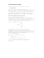
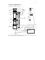
CHAPTER 4 OVERVIEW OF THE ACC PROGRAM:
RUN file
ACC 2
TIMER file
SEQUENCE file
Visual Basic 5
DDE
Dynamic
Data
Exchange
RS-232
COM2:
PMIS ver.. 3.5
RS-232
COM1:
I/O from
AT200
PC board
SMARTMR
Photmetrics
CH200
CCD camera
Smartmtr
electronics
Garmin GPS
receiver
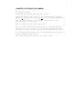
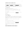
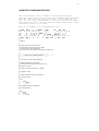
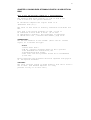
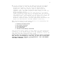
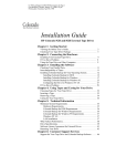
Figure 1: Overview of the camera computer system. The Garmin
GPS receiver is optional. By the time, a Network Time Server is
used instead of the GPS. The Time Server communicates via the
LAN.
9
The filter wheel, the intensifier and the shutter is
controlled by the SMARTMTR program. The SMARTMTR
program in use is called Norway.prg. The CCD camera is
controlled by the PMIS program. The PMIS program also
cover the RS-232 communication (thin cable) to the
SMARTMTR program. This is done via the RS-232 COM1: port.
When inspecting the camera system the operator should also
watch the PMIS window.
The ACC2 program is a Visual Basic 5 program. It communicate
with the PMIS program. The task of the ACC2 program is
to determine the times the camera should operate and what
it should do when it operates.
VisualBasic(ACC2)--> PMIS(macros)--> SMARTMTR(Norway.prg)
The information from the ACC2 program is written in the
upper text panel in the ACC2 window. Every line starts with the
time when the message is written. The last line written in the
ACC2 text panel is the top line.
The highly unstable PC clock is corrected by the Garmin GPS
12XL receiver. This is done via a RS-232 cable on the COM2:
port. The messages from the part of the program handling the
GPS interface is shown in the lower text panel in the ACC2
window. The program checks every other minute if the PC clock
should be corrected. The communication to the GPS receiver is
handled by Visual Basic Communication control , MSComm .
The communication between the ACC2 program and the PMIS program
is handled with DDE (Dynamic Data Exchange) protocol. The
middle text panel in the ACC2 window is used as a DDE
communication buffer.
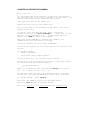
10
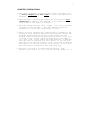
CHAPTER 5 THE ACC2 CONTROL FILES:
The control files for the ACC2 program is located at the
C:\acc\seq directory. The ACC2 program uses 3 control files:
The run file, the timer file and the sequence file.
The operator should write these three files. The recommended
editor is the Windows 95 notepad program. EDIT in DOS can also
be used. The format of the control files has to be DOS ASCII.
(MARK: Then do not use Word, Word Pad etc. ..)
1) The run file:
----------------The run file is named RUN.ACC .
The RUN.ACC file contains 1 executable line.
Lines starting with # in first column are comment lines.
When the first line in the RUN.ACC line has the content:
RUN <filename>
The <filename> is the full path of the timer file the camera
should run.
Example:
RUN c:\acc\seq\timer_2.fil
2) The TIMER file:
-------------------The current timer file is the filename after the RUN in run
file. In the Example above the current timer file is named
"timer_2.fil" in c:\acc\seq\ directory. It is recommended the
operator uses DOS compatible file names when he creates new
timer files.
The timer file defines the intervals when the camera
should run.
The timer file has the format:
start yyyy-mm-dd hh:mm:ss stop yyyy-mm-dd hh:mm:ss <filename>
The <filename> is the full path of a sequence file.
Note: The sequence file name can be different at
different lines in the timer file.
Example:
start 1997-11-12 06:36:30 stop 1997-11-12 22:38:00 c:\acc\seq\test_a.seq
start 1997-11-13 06:36:30 stop 1997-11-13 22:38:00 c:\acc\seq\test_b.seq
start 1997-11-14 06:36:30 stop 1997-11-14 22:38:00 c:\acc\seq\test_a.seq
11
The line executed in the timer file is the line where
the current time is within the listed interval.
The operator writing a new timer file must follow this format
exactly. The format of the sequence file name can be different,
i.e. it can be at another hard-disk and in another directory.
The current version of the ACC2 program can accept
maximum 100 lines from the timer file.
Note: In order for the ACC2 program to read the correct date
and time format the Windows 95 date and time format must be set
correctly. The date and time is every second printed in the
right upper corner of the ACC2 window. This format has to be
(If this ever has to be changed, it is changed by using the
Regional Settings in the Windows 95 Control Panel):
yyyy-mm-dd hh:mm:ss
Example:
1997-11-15 10:17:24
CORRECT DATE AND TIME:
If the Garmin GPS 12XL receiver is not used, the date and time
of the computer should be set to correct UT time. This is done
in the Windows 95 control panel, Date/Time .
3) The sequence file:
--------------------The current sequence file is the filename at the end of the
line executed in the current timer file. The sequence file
determines the type of sequence executed. The '$' below are
numerical characters ('0', '1', .. '9').
Lines starting with # in first column are comment lines. The
other lines in the sequence file, must be executable lines.
When the ACC2 program execute a sequence the sequence length is
60 seconds.
The executable lines have the
format:
t$$ f$ e$$$ g$ s$ u$ c$
or
b$$ f$ e$$$ g$ s$ u$ c$
t$$ is the second in the minute when program is running in
normal mode. b$$ is the second in the minute when program is
12
running in burst mode. The default is normal mode, but the
operator can change to burst mode by pressing the Burst option
button in the ACC2 window.
When ACC_USE_CONTROL_SEC is 1 in the configuration file :
When composing the sequence file the operator must allow the
program to read the run file and the timer file or the Garmin
GPS 12XL receiver. This is done the ACC_CONTROL_SEC second
specified in the configuration file. The ACC2 program needs
about 2 seconds to perform these tasks.
When ACC_USE_CONTROL_SEC is 2 in the configuration file:
In this case the c$ is used (see below).
f$
is the filter number
$ = 1 for 630.0 nm
$ = 2 for 557.7 nm
$ = 3 for 427.8 nm
e$$$ is the exposure time in milliseconds
g$
s$
u$
c$
.
.
is the intensifier gain (0, 1, 2 or 3)
is save image to hard disk (1 = yes, 0 = no)
is save image to external disk (1 = yes, 0 = no)
is read the run file and the timer file or the Garmin
GPS 12XL receiver after the image is captured (1 = yes,
0 = no)
Example:
# sequence file: x1.seq
# The camaera run either in normal or burst mode
# t* is normal mode (* is seconds in the minute)
# b* is burst mode (* is second in the minute)
# f* is filter number (1: 630.0nm , 2: 557.7 nm, 3: 427.8 nm)
# g* is intensifier gain (0,1,2 or 3)
# e* is exposure time in ms
# s* save to harddisk, 1: yes , 0: no
# u* save to network disk, 1: yes , 0: no
# c* is perform control check after this image , 1: yes, 0: no
#
# normal mode sequence
t0 f1 g3 e2000 s1 u1 c1
t30 f2 g2 e1000 s1 u0 c0
#
# burst mode sequence
b0 f1 g3 e2000 s1 u1 c1
b10 f2 g2 e1000 s1 u0 c0
b20 f1 g3 e2000 s1 u0 c0
b30 f2 g2 e1000 s1 u0 c0
b40 f1 g3 e2000 s1 u0 c0
b50 f2 g2 e1000 s1 u0 c0
#
# end of file
This example shows the camera should take two images pr. minute
in normal mode and six images pr. minute in burst mode. The
13
filters should be 630.0 nm (f1) and 557.7 nm (f2). The gain is
set to 3 (maximum) for the 630.0 nm filter and 2 for the 557.7
nm filter respectively (g$). The exposure times should be 2000
and 1000 milliseconds (e$), and all images are stored at the
harddisk (s1). At the start of the minute the image is also
copied to network disk (u1). If the ACC_USE_CONTROL_SEC is 2 in
the configuration file the program read the run file and the
timer file or the Garmin GPS 12XL receiver. This is done after
the first image is captured in each sequence (c1).
Note: The ACC2 program assumes the interference filters
are inserted in this sequence:
filter no 1, 630.0 nm
filter no 2, 557.7 nm
filter no 3, 427.8 nm
Note: Because when saving to network disk the ACC2 program
copies the image file from harddisk to network disk the line
. . . . . s0 u1
in the sequence file will not work.
The ACC2 program store the sequence selections in an array with
one element for each second. The consequence of this is: The
burst mode settings will overwrite the normal mode settings for
the seconds. As an example you have created a sequence file
as this example:
# normal mode sequence
#. . . .
t30 f2 g2 e1000 s1 u0 c1
#. . . .
# burst mode sequence
#. . . .
b30 f1 g3 e2000 s1 u0 c1
#...
In this example the settings for burst mode at second 30 will
overwrite the settings for normal mode for second 30. What then
actually will execute at second 30 when the camera is running
in normal mode is:
t30 f1 g3 e2000 s1 u0 c1
It is then recommended to have equal settings for burst and
normal mode for the same second.
14
CHAPTER 6 IMAGE FILE NAMES:
The image ACC2 program stores images at directory:
x:\data\images
(Note: x: is d: for the Unis/UiO camera no 1.)
Then after a backup the operator can remove all subdirectories
at x:\data\images . (Or he can remove the images directory.
Afterwards he the has to create the images directory again.)
If the Windows95 "Recycle Bin" is used the files has to be
emptied from the "Recycle Bin" afterwards. The DOS command
DELTREE can be used, (e.g. in DOS deltree 971123 971124).
The x:\data\images directory must exist.
(x: is d: for the Unis/UiO camera no 1.)
The ACC2 program automatically creates a subdirectory at
x:\data\images for each day. The format of this directory name
is 'yymmdd' . Then on this new directory it creates a new
subdirectory for each hour. The format of this directory name
is 'hh' . An example of this directory structure is:
X: data -- images -- 971123 -- 05
|
|- 06
|
|- 21
|
-- 971124 -- 05
|- 06
|- 07
|- 08
The ACC2 program can also create long file names
(yymmddhhmmss.fs). However, the PMIS program which is
responsible for acquiring the data from the camera and storing
the images with the (from ACC2) selected file names can only
accept DOS compatible file names. Then we have to select the
short file name option in the configuration
file,(ACC_LONG_IMAGENAME) .
The (short) file names has the format :
'yymmddhh.%%&'
'yymmddhh' denotes the date and time.
'%%' is a hexadecimal counter for this filter code.
00 <= '%%' <= FF , i.e the counter can count 255
images/hour.
15
The filter code '&' is:
"r" for the filter no 1, 630.0 nm
"s"
"t"
"u"
"v"
"g" for the filter no 2, 577.7 nm
"h"
"i"
"j"
"k"
"b" for the filter no 3, 427.8 nm
"c"
"d"
"e"
"f"
The explanation of this is. The ACC2 program creates a
new directory for each hour. Each image is stored in
one file. Normally "r" is the filter code for the 630.0 nm
filter no 1. However, if more than 256 (00 to FF Hex) images
for filter no 1 are stored at each directory, the code for
filter no 1 switches to "s". If more than 512 images are stored
for filter no 1 in this hour, the code switches to "t", etc. .
As an example the images stored at data\images\971124\14
directory is:
97112414.00R
97112414.00G
97112414.01R
97112414.01G
97112414.02R
97112414.02G
97112414.03R
97112414.03G
97112414.04R
Windows explorer can be used to show the on line occurrence of
new data files at current directory.
When the ACC2 program is stopped and then started again the
image counter (%%) automatically continue after the last image
file written to harddisk. No image files are overwritten. This
information is stored in the rcount.dat, gcount.dat and
bcount.dat files in each directory.
16
CHAPTER 7 THE IMAGE FORMAT:
The image format is the PMIS version 3.5 image format. It is
described in the PMIS User's manual, Version 3.5 at page 243.
It contains an header and then a 513x512x16 bits image. The
ACC2 program uses the 100 character image header comment part
for storing information about the camera system.
The camera delivers 12 bit data, but the PMIS software stores
16 bit data.
An example of the start of such a comment is:
D1997-12-07_14:51:29W557.7nmF2G0E230....
Upper case letters "A" - "Z" are used as identifiers.
"D"
"W"
"F"
"G"
"E"
denotes
denotes
denotes
denotes
denotes
date,
example:
Wavelength,
....
filter number
....
intensifier gain ....
exposure time (ms)....
D1997-11-24_17:11:30
: W557.7nm
: F2
: G0
: E230
The rest of the comment parameters are read directly
from the configuration file c:\acc\config\config.acc
below).
"N"
"S"
"L"
"O"
"H"
"R"
"C"
"X"
"Y"
"A"
"B"
"V"
CAMERA_NUMBER
STATION_NAME
STATION_LAT
STATION_LON
STATION_ALT
IMAGE_MAX_ROWS
IMAGE_MAX_COLUMNS
IMAGE_X1
IMAGE_Y1
IMAGE_A
IMAGE_B
CAMERA_NORTH
(see
17
CHAPTER 8 COPYING IMAGES TO A NETWORK DISK:
The ACC2 program can save the image on a network disk. Here it
can be read by «another program» which can process and display
the on-line image data at e.g. the World Wide Web. The «another
program» is not a part of the ACC2 program and can not be run
on the camera PC. (The Geomapper program written by Dagfinn
Opsvik can be used as the «another program».)
The settings in the configuration file (see below) must then
be:
ACC_NET_IMAGE_ALLOW 1
ACC_NET_IMAGE_DIR y:\directory1\directory2 ..
The y:\directory1\directory2.. must be a network disk mounted
as y: on the camera PC. Y: can be any character. (As an example
in Oslo the ACC_NET_IMAGE_DIR g:\tmp\pmis\images was used).
The network disk can also be the main harddisk C:, e.g. C:\tmp
.
The line in the sequence file is .. s1 u1 .. when the images
should be stored at a network disk.
In the ACC_NET_IMAGE_DIR directory the sub directories 427.8nm
, 557.7nm and 630.0nm must exit. (The ACC2 program will not
create any directories at the network disk.) The ACC2 program
will then save the images «from» the respective filters on
these sub directories.
On the network disk the image names are:
pmis.0
pmis.1
pmis.2
pmis.3
pmis.4
pmis.5
pmis.6
pmis.7
pmis.8
pmis.9
The pmis.0 is the first image saved. When the pmis.9 is saved
the next image is pmis.0, pmis.1,, … in an endless cycle.
It is the «another program» responsibility not to read the
image at the network disk before the ACC2 program has finished
saving it. The possible solution is then to check the file size
which is 525492 bytes for each image.
When ACC_NET_IMAGE_DUMMY is 1 in the configuration file a small
file dummy.dat is copied to the network disk after the pmis
image is copied. This file can be used to synchronise the
reading. The dummy.dat file can be deleted by the «another
program».
18
The ACC2 program copies the image from the harddisk to the
network disk. In this case the s0 u1 line in the sequence file
will not work.
19
CHAPTER 9 CONFIGURATION FILE:
The configuration file is named c:\acc\config\config.acc .
This file must exist. The file contains comments which explains
the file. When the user knows the setup of the camera he can
fill inn the correct parameters in this file. Because the upper
case characters "A" - "Z" are used as comment identifier, these
characters should not be used.
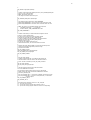
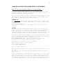
Here is an example of a configuration file:
# ####
##
#
##
##
##
#
# ####
#
####
#
# ##### #
####
##
### ###
#
#
## # #
#
#
# #
# # # #
#
# # # # ##### # #
# # #
#
#
# # # #
#
#
#####
##### #
# #
#
# # ##
#
#
#
# ## #
# # # # #
#### # #
#
#
#### ## #
# ###
###
#
# config.acc
#
#
# This file must be at c:\acc\config directory.
#
# This file is read when the ACC2 program is starting.
# This file contains the ACC2 configurations
# Lines starting with # are omitted (i.e. these lines are comment lines).
#
#
# -----------------------------------------------------------------------# ---------- THIS IS FOR THE CAMERA OPERATION --------------------------# -----------------------------------------------------------------------#
#
# This information is for the CameraConfigStruct . . . . . . . . . . . . .
#
# Location of RUN.ACC file : ACC_RUNDIR
# The RUN.ACC file determines if the camera is run or not.
#
ACC_RUNDIR c:\acc\seq
#
# Location of the sequence directory : ACC_SEQDIR
#
ACC_SEQDIR c:\acc\seq
#
#
# Location of the smartmtr macros: ACC_MACROS
#
# On Unis/UiO camera 1 :
#
# pmis
# |__ macros
#
|__ Smartmtr
#
|__ Test
#
# ACC_MACROS c:\pmis\macros\Smartmtr
#
# On Unis/UiO camera 2 :
#
# pmis
# |__ images
# |__ Macros
#
|__ Norway
20
#
ACC_MACROS c:\pmis\Macros\Norway
#
#
# Location of the image storage media top directory: ACC_STORAGE_MEDIA_DIR
# (when s1 is set in sequence files)
# MARK: This directory must exist
# The images are stored in this directory tree.
#
ACC_STORAGE_MEDIA_DIR c:\data\images
#
#
# Type image file name created: ACC_LONG_IMAGENAME
# When LONG_IMAGENAME is 1 the long version of the file names are used
# When LONG_IMAGENAME is 0 the short version of the file names are used
#
# MARK: The version 3.5 of the PMIS software only acceps DOS
#
compatible file names (8 + '.' + 3 characters).
#
Therefore the ACC_LONG_IMAGENAME has to be 0
#
ACC_LONG_IMAGENAME 0
#
#
# Location of the directory on network disk where images are stored
# (when u1 is set in sequence files)
# In order for the images to be stored at network disk the
# operator must set 1 after ACC_NET_IMAGE_ALLOW
# In order to inhibit the storage of images at the network disk the
# operator must set 0 after ACC_NET_IMAGE_ALLOW
# When this option is used:
# In the ACC_NET_IMAGE_DIR directory the
# sub directories 427.8nm , 557.7nm and 630.0nm must exist.
#
# When the ACC_NET_IMAGE_DUMMY is 1 the dummy file dummy.dat is
# copied to the network image directory after the image
# is copied to this location.
#
ACC_NET_IMAGE_ALLOW 1
#ACC_NET_IMAGE_DIR g:\tmp\pmis\images
ACC_NET_IMAGE_DIR c:\tmp\images
ACC_NET_IMAGE_DUMMY 0
#
#
#
# ACC_NET_INFO_ALLOW
# Location of the INFO.ACC file . The INFO.ACC file contains the
# same information as the text written in the information window
# in ACC. This file is created only if ACC_NET_INFO_ALLOW is 1
#
ACC_NET_INFO_ALLOW 0
ACC_NET_INFO_DIR g:\tmp\acc\info
#
#
# The ACC2 program needs to check if the time intervals
# set in the TIMER files are reached.
# It also needs to check the GPS if the PC clock is to be changed
# Which second in the minute the RUN and TIMER files are checked
# is the ACC_CONTROL_SEC .
#
# ACC_USE_CONTROL_SEC = 1 use the ACC_CONTROL_SEC second in minute
# ACC_USE_CONTROL_SEC = 2 use the c# in sequence file, i.e. control after
#
an image capture
ACC_USE_CONTROL_SEC 2
ACC_CONTROL_SEC 57
#
#
# If the GPS receiver should be used or not : ACC_USE_GPS
# 0 : no do not use the receiver
# 1 : yes use the receiver, program stops if receiver is not on
# 2 : yes use the receiver, program continue if receiver is not responding
21
#
ACC_USE_GPS 2
#
# Usually the computer access the GPS via the COM2: port
# This might be named with another port number.
# For the Unis/UiO camera no 1 COM4: is used, (ACC_GPS_PORT 4).
# For the Unis/UiO camera no 2 COM2: is used, (ACC_GPS_PORT 2).
#
ACC_GPS_PORT 2
#
# -----------------------------------------------------------------------# ---------- THIS IS FOR THE IMAGE COMMENTS -----------------------------# -----------------------------------------------------------------------#
#
# This information is for the StationInfoStruct . . . . . . . . . . . . . .
#
# Camera number:
# Unis/UiO camera no 1 (i.e. Longyearbyen) : 1
# Unis/UiO camera no 2 (i.e. Ny Aalesund) : 2
CAMERA_NUMBER 2
#
# station name ("lyr", "nya", "dmh") , lower case in image comments
# the length of the station name has to be 3 characters
# The station letter is one letter which will be added
# at the end of the file names (when long file names are used)
STATION_NAME nya
STATION_LETTER N
#
# station geographic latitude, geographic longitude and altitude
# in meters above sea level
STATION_LAT 78.92
STATION_LON 11.95
STATION_ALT 25.00
#
#
#
#
# This information is for the CameraSetupStruct . . . . . . . . . . . . . .
#
# rows and columns in image
IMAGE_MAX_ROWS 513
IMAGE_MAX_COLUMNS 512
#
# zenith location in image (origo is left lower corner)
IMAGE_X1 256
IMAGE_Y1 256
#
# horizontal radius of the image ellipse
IMAGE_A 300
# vertical radius of the image ellipse
IMAGE_B 300
#
# angle in degrees from image y-axis to geographic north
# (positive is counter clockwise)
IMAGE_NORTH 10.00
#
#
# end of file
22
CHAPTER 10 SAVING DATA AT DAT STORAGE MEDIA:
This is for the Unis/UiO camera no 1 (Longyearbyen).
When saving data at the DAT tape the Adaptec Backup,
abackup, program is used.
Using the abackup program:
1.
2.
3.
4.
Backup , Data_disk_d (D:)
mark D: data, a 'v' tag appears, (Use «right mouse button» and Tag)
NextStep>
Mark the device HP 35480A
5.StartBackup>
This backup last for approximate 1 hour / GB .
23
CHAPTER 11 SAVING DATA AT PINNACLE APEX 2 X 2GB OPTICAL
DISK:
This is for the Unis/UiO camera no 1 (Longyearbyen).
The Pinnacle Apex drive capacity is 2 GB on side A and
2 GB on side B of the optical diskette.
At the Micron computer the logical drive is F:
(Removable disk (F:)).
The files on this drive is directly accessible from Win95 and
DOS.
Fist time a new optical diskette is used ,it has to
be formatted on both sides A and B. (It is done
in approximate 5 minutes.) The formatting is explained
in the EZ-SCSI 4.0L , Software User Manual, page 43-51.
FORMATTING:
Put the new diskette in the CD-ROM. (First with A: towards
right.) Go to Ms-DOS and type:
afdisk
1.Press enter when :
2.HA #1 - Target 2 Pinnacle Apex 4.6 GB is printed
3.Use Extended Bios Translation, Yes
4.Standard Hard Disk Format
5.The start and end cylinders should be as recommended
(0 and 250).
After formatting the procedure should be repeated with page B:
of the Optical Diskette.
COPYING:
The files could be copied or moved directly from the D: disk to
the F: disk. (The Windows Explorer is a very
powerful utility to do this with.)
24
CHAPTER 12 USING THE HP SURE STORE T4i STREAMER:
This is for the Unis/UiO camera no 2 (Ny Ålesund).
The user should read Chapter 4 in the documentation for the
streamer (Hewlett Packard, HP SureStore T4, T4i/e , User’s
Guide, Caring for Your Tape Drive).
The Colorado Backup program is used for storing images at the
HP SureStore T4i tape drive. Press the Colorado Backup icon,
(or start it using the Start pop up menu).
FORMATTING:
The new tapes needs to be formatted before used. (Format will
erase all data on already used tapes). In the Colorado Backup
window:
Tools->Format Tape ,… .
The actual formatting of the tapes only last for about 10
seconds.
BACKUP:
In the Colorado Backup window press on the (C: ) in the left
panel. Then all directories on the harddisk C: is expanded in
the right panel in a similar fashion as in the Microsoft
Windows Explorer. Press on each directory to be backed up. The
selected directories will then be marked with the ν sign.
The ACC2 program stores images at data\images directory. Then
in our case the data directory needs to be backed up. (Mark:
This can be changed in the configuration file,
ACC_STORAGE_MEDIA_DIR). When the user has selected the
directories for backup press the Next >> button.
Then select the backup drive, HP T4000s .
Next select a name for the backup.
Use ν Verify backup and
ν Use data compression .
At last press Finish >> .
The writing to tape and the verify processes uses about ½ hour
pr. GB.
Do not pull out the tape when the computer writes (or reads)
data to it.
After the backup is finished pull it straight out of the drive.
Move the red protect tab into the locked (read only) position.
Use the labels which is inside the tape plastic cover. Store
the tape in the plastic cover. See in the user manual page 4-6
for further information. (If the tapes or the tape drive has
25
been exposed to low temperature, let it warm up slowly for
several hours before using it.)
26
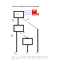
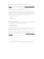
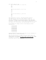
CHAPTER 13 AUTOMATIC UPDATE OF PC CLOCK:
Note: The use of GPS time is optional. The preferred time
source is the Tardis95 program which updates the PC clock via
the LAN to a Network Time Server.
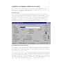
Network Time Server
The Tardis95 program starts automatically when the computer
boots. A small blue icon shall be visible right besides the PC
clock in the down-right corner of the monitor. To change the
settings, just click on the icon. The settings should be as
shown in the figure. The IP address to NPF time server is
currently 193.156.10.100 as shown in the figure. The program
communicates via the computers network connection.
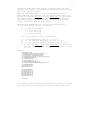
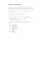
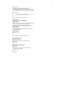
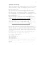
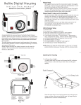
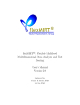
THE GARMIN GPS 12XL RECEIVER (OPTIONAL)
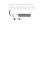
The setup of the Garmin GPS 12XL receiver is shown in Figure 2.
The Garmin GPS 12XL receiver must be mounted with open view to
at least ≈ ½ of the sky. Then it will «see» several of the GPS
satellites in polar orbit.
The mounting bracket can be unscrewed and remounted in several
positions. The data cable from the Garmin GPS 12XL is connected
to the connector box. This connector box is having an input
connector for 12VC (from the AC to DC converter). It also has a
RS-232 connection. This is connected to the PC COM2: port. Only
the TxD, RxD and GND connector
is used in the PC.
27
When the Garmin GPS 12XL is operating on battery power or do
not find any satellites it automatically shut down after 15
minutes.
The mscommtry, (c:\acc\testprog\mscommtry.exe), can be used to
test the GPS connection. This is started with the TestGPS icon.
When this program is used simultaneously as the ACC2 program a
conflict on using the COM2: port will appear.
GPS
data connector
RS-232
on PC
brown
2
white
3
black
5
12V
fuse
AC DC
adapter
connector
(gnd is center
pin)
28
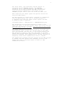
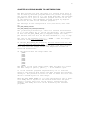
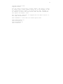
CHAPTER 14 CAMERA SETUP:
This chapter gives an overview of the camera setup.
180
° fish-eye lens
Front lens:
Front safety
shutter
and f4
Garmin
GPS 12XL
Safety
light
detector
Data
cable
Filter wheel
Connector box
Focusing
tube
RS-232
to COM2:
Middle lens: f 0.95 and 19 m (at blacks)
AC to DC
adapter
Image
intensifier
220 VAC
Focusing
tube
Bottom lens: f1.2 and 7m (at black •)
Smartmtr ctrl, RS-232, to COM1:
PhotometricsCC
D camera
Data cable
Data cable
Photometrics
CC200 Camera
Controller Unit
110 VAC
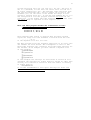
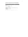
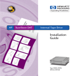
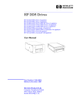
Figure 2: This figure is showing the Unis/UiO camera system. The focus settings for the middle and lower lens (19m amd
7m) are for the Unis/UiO camera no 2 during the 97/98 winter season.
29
Read the first 7 pages in the document All-Sky Imaging System
for University of Oslo, KEO Consultants, 12/5/95.
The camera is installed as shown in Figure 2. Three cables are
connected from the PC to the camera system.
• Optional! One cable from the PC COM2: to the GPS Connector
box.
• One cable from the PC COM1: to the Smartmtr control on the
Camera U-channel.
• One cable from the AT200 camera controller PC board to the
Photometrics CC200 Camera controller unit. Mark: Do not
connect this to the PC Centronix port. (The PC Centronix port
has a similar connector as the AT200 board.)
At least two persons are needed to mount the camera. Remove the
fish-eye lens before mounting the camera. (Put on the lens cap
both on the camera top and both sides of the fish-eye lens).
After mounting the camera adjust it to be exactly vertically.
Put the fish-eye lens back on. It should have maximum opening
f4 and ∝ . Connect the front shutter cable to the front
shutter , (see Fig. 2). The other cable is connected to a
safety light detector and should be mounted at a proper place.
Connect the 1.5m data cable from the Photometrics CC200 Camera
Controller Unit to the Photometrics CCD camera. This has to be
done in this sequence:
1. Connect the cable to the Photometrics CC200 camera
Controller Unit. It is marked which side of the cable you
should use and what connetor on the Controller Unit to be
used.
2. Remove the blue shorting plug on the backside of the camera,
and connect the cable immediately to the camera. (The camera
should always either have the terminator on, or be connected
to the Controller Unit).
Both the CC200 controller Unit and the camera should be
connected to 110 VAC power.
Optional! The Garmin GPS receiver is connected as shown in
Figure 2. The 12V AC to DC adapter should be connected to 220
VAC power.
The PC used is a
hardware key for
port. The PC can
required for the
standard PC running Microsoft Windows 95. The
the PMIS program is connected to the centronix
be connected to the ethernet, but that is not
camera operation.
30
CHAPTER 15 FOCUSING:
One of the drawbacks of a digital camera with no analog output
is the difficulty to focus it. The Unis/UiO cameras consist
of three adjustable lenses for focusing.
1) Front fisheye lens:
This should use the UV filter setting in the lens filter
setting. (MARK: This is not the interference filter wheel,
630.0nm, … .) This UV filter is marked with white characters.
The other filters are marked with yellow or red characters.
The lens settings in the front fisheye lens should be set fully
open (f-stop to f4) and focused to ∞ .
2) The middle lens:
This is the filter re-imaging optics, CANON camera lens in
front of the image intensifier.
As with the other lenses it should be set fully open (f-stop ,
f0.95). The focus of this lens has to be adjusted.
3) The bottom lens:
This is the intensifier re-imaging optics. This is the NIKON
camera lens in front of the CC200 camera head.
As with the other lenses it should be set fully open (f-stop,
f1.2). The focus of this lens has to be adjusted.
… … … … … … ...
Only the PMIS program is used when focusing the camera.
The user knows from the experience with the sequence files
the best settings for the image intensifier gain and exposure
time for the various filters (and for the open filter). When
focusing towards stars (or planets) the filter settings with
open filter should be used, then a shorter exposure time must
be selected.
One person should watch and control the computer while the
other person turn the lenses in the camera hut.
The focusing can be done as:
user->comopen->1
user->filterwheel->1
user->initgain->1
user->initpower->1
user->shutterctrl->1
Be careful now, no lights in the camera hut. The intensifier
is now continuously exposed to light and could easily be
damaged.
Then in the Image_1 window:
31
acquire->expose->1000
acquire->focus
Now the camera continuously catches images. The Image_1 window
is acting like a video camera screen. It is now easiest to see
the instantaneously effect of focusing each lens. Perhaps it
is easiest to start with the bottom lens and then afterwards
the adjust the middle lens.
The continuously exposure is stopped with the <ESC> button or
the right mouse button.
Then remember to shut down the camera again with:
user->shutterctrl->0
user->initgain->0
user->initpower->0
user->comclose
32
CHAPTER 16 POSSIBLE ERRORS:
1) If the ACC2 program do not understand your new
timer or sequence file the reason can be that it is not a real
ASCII file. Rewrite the sequence file with EDIT in DOS.
Then try once more.
2) If the image processing capabilities of the PMIS program is
used when the ACC2 program is running, the communication
between ACC2 and PMIS can be lost (timed out). This message
window will appear:
Microsoft Visual Basic
Run time error '286'
Timeout while waiting for DDE response
Then the user has to stop the ACC2 program, (Stop and Exit).
Then he can start it again. The ACC2 program remember the last
image number stored to harddisk and will continue storing the
images with image number after this. No files are overwritten.
3) If the ACC2 program "runs off" the end of the timer file
the program will stop. It is then wise to have a sequence in
December 1999 as the last sequence. (The ACC2 program have
not been checked for the «year 2000 problem».)
4) After changing the timer file or the sequence file, the ACC2
program should be restarted
5) If the Garmin GPS 12XL receiver is running on battery power,
or lost track of all GPS satellites for a period of 10
minutes, it shuts itself off. It has to be restarted
manually. (The first data after a manual start is not the
time sequence and is ignored by the ACC2 program.)
6) If you in the sequence file have selected different settings
for normal mode and burst mode for the same second, the
normal mode selection for this second is overwritten by the
burst mode selection.
7) The PMIS software requires the Screen is set to 256 colours.
This is set in the Windows 95 Control Panel, Screen. This
must be set to 256 colours even if you have a great display
adapter with a lots of memory. This implies the computer
can not display a lot of colours at the same time. Then in
order to display the image the Image_1 window must be in
focus. The user must click the left mouse button when the
mouse cursor is in the Image_1 window in order to make the
window in focus. Then the upper border of the Image_1 window
is blue (not grey). (Hopefully the user has not changed the
standard Windows 95 windows colours).
33
8) If the connection between the PMIS program and the AT200
Interface board is lost the error when starting the PMIS
program will appear: ‘Can not find the AT200 camera
controller’. The first step is then to power down the
computer, wait for about 30 seconds and then start the
computer again. The PMIS program is then likely to find the
AT200 Interface board.
If the problem still exists the reset button on the AT200
camera controller might have to be pushed when the starting
the computer. This reset button is located on the top of the
interface board, (the computer must be opened to be able to
press the reset button), see AT200 CCD Camera System,
Hardware reference manual and the appropriate World Wide Web
pages from Photometrics and GKR Computer Consulting.
9)If the HP SureStore tape bacup drive is not responding and
gives the following error message:
1. Shutdown and restart computer
2. Run ScanDisk and Defrag
3. Close other applications
4. Try a different tape
5. Uninstall Colorado Backup, and reinstall
then the most likely reason is that there is a bad electrical
connection to the backup drive. Open the computer, deconnect
and reconnect the power connector to the tapedrive, and do the
same with the SCSI connector (both ends).
Please take any precaution to prevent Electro Static Discharge,
ESD. The air on Svalbard is very dry, so the risk of ESD when
working inside the computer is considerable. THIS CAN DAMAGE
THE WHOLE COMPUTER! (Espen 99/01/15)