1
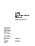
HP 1920 Gigabit Ethernet Switch Series
Getting Started Guide
5998-5626
Part number: 5998-5626
Document version: 6W101-20140820
Legal and notice information
© Copyright 2014 Hewlett-Packard Development Company, L.P.
No part of this documentation may be reproduced or transmitted in any form or by any means without
prior written consent of Hewlett-Packard Development Company, L.P.
The information contained herein is subject to change without notice.
HEWLETT-PACKARD COMPANY MAKES NO WARRANTY OF ANY KIND WITH REGARD TO THIS
MATERIAL, INCLUDING, BUT NOT LIMITED TO, THE IMPLIED WARRANTIES OF MERCHANTABILITY
AND FITNESS FOR A PARTICULAR PURPOSE. Hewlett-Packard shall not be liable for errors contained
herein or for incidental or consequential damages in connection with the furnishing, performance, or
use of this material.
The only warranties for HP products and services are set forth in the express warranty statements
accompanying such products and services. Nothing herein should be construed as constituting an
additional warranty. HP shall not be liable for technical or editorial errors or omissions contained
herein.
Contents
Preparing for installation ············································································································································· 1 Safety recommendations ·················································································································································· 1 Examining the installation site ········································································································································· 2 Temperature/humidity ············································································································································· 2 Cleanness ·································································································································································· 2 EMI ············································································································································································· 3 Installing the switch ······················································································································································ 4 Mounting the switch in a 19-inch rack by using mounting brackets ··········································································· 4 Mounting the switch on a workbench ·····························································································································7 Mounting the switch on a wall ········································································································································ 7 Connecting cables ···························································································································································· 9 Connecting network cable ······································································································································ 9 Installing the SFP transceiver module and optical fibers ······················································································ 9 Connecting the console cable ······························································································································ 10 Connecting the AC power cord ··························································································································· 10 Connecting the DC power cord ··························································································································· 11 Verifying the installation ················································································································································ 12 Accessing the switch for the first time ······················································································································· 13 Setting up the configuration environment ···················································································································· 13 Connecting the console cable ······································································································································ 13 Console cable ························································································································································ 13 Connection procedure ·········································································································································· 14 Setting terminal parameters ·········································································································································· 14 Powering on the switch·················································································································································· 17 Verification before power-on ······························································································································· 17 Powering on the switch ········································································································································· 17 Support and other resources ····································································································································· 19 Contacting HP ································································································································································ 19 Subscription service ·············································································································································· 19 Related information ························································································································································ 19 Documents ······························································································································································ 19 Websites································································································································································· 19 Conventions ···································································································································································· 20 Appendix A Chassis views and technical specifications ························································································ 22 Chassis views ································································································································································· 22 1920-8G ································································································································································ 22 1920-16G ······························································································································································ 22 1920-24G ······························································································································································ 23 1920-48G ······························································································································································ 23 1920-8G-PoE+ (65W) ·········································································································································· 24 1920-8G-PoE+ (180W) ······································································································································· 24 1920-24G-PoE+ (180W) ····································································································································· 25 1920-24G-PoE+ (370W) ····································································································································· 25 Physical specifications ··················································································································································· 26 Chassis dimensions and weights ························································································································· 26 Ports and interface card slots ······························································································································· 26 Environmental specifications ········································································································································· 27 i
Power specifications ······················································································································································ 27 AC input voltage specifications ··························································································································· 27 RPS DC input voltage specifications and RPS compatibility ············································································· 27 Power consumption specifications for non-PoE switches ··················································································· 27 Power consumption specifications for PoE switches ·························································································· 27 Cooling system ······························································································································································· 28 Appendix B LEDs ························································································································································ 29 Power LED ······························································································································································ 29 Copper port LEDs ·················································································································································· 29 Fiber port LEDs ······················································································································································· 29 RPS LED··································································································································································· 30 Appendix C Troubleshooting ···································································································································· 31 ii
Preparing for installation
The HP 1920 Gigabit Ethernet Switch Series includes models listed in Table 1.
Table 1 HP 1920 Gigabit Ethernet Switch Series models
Product code
HP description
Alias
RMN
JG920A
HP 1920-8G Switch
1920-8G
HNGZA-HA0008
JG923A
HP 1920-16G Switch
1920-16G
HNGZA-HA0011
JG924A
HP 1920-24G Switch
1920-24G
HNGZA-HA0012
JG927A
HP 1920-48G Switch
1920-48G
HNGZA-HA0015
JG921A
HP 1920-8G-PoE+ (65W) Switch
1920-8G-PoE+ (65W)
HNGZA-HA0009
JG922A
HP 1920-8G-PoE+ (180W) Switch
1920-8G-PoE+ (180W)
HNGZA-HA0010
JG925A
HP 1920-24G-PoE+ (180W) Switch
1920-24G-PoE (180W)
HNGZA-HA0013
JG926A
HP 1920-24G-PoE+ (370W) Switch
1920-24G-PoE (370W)
HNGZA-HA0014
Non-PoE
PoE
IMPORTANT:
For regulatory identification purposes, the switches are assigned Regulatory Model Numbers (RMNs). The
RMNs should not be confused with the marketing name HP 1920, or the product codes.
Safety recommendations
To avoid any equipment damage or bodily injury, read the following safety recommendations before
installation. The recommendations do not cover every possible hazardous condition.
•
To avoid damage to the electrolytic capacitor in the switch, do not store the switch without power for
more than one year.
•
Before cleaning the switch, remove all power cords from the switch. Do not clean the switch with a
wet cloth or liquid.
•
Do not place the switch near water or in a damp environment. Prevent water or moisture from
entering the switch chassis.
•
Do not place the switch on an unstable case or desk. The switch might be severely damaged in case
of a fall.
•
Ensure good ventilation of the equipment room and keep the air inlet and outlet vents of the switch
free of obstruction.
•
Make sure the operating voltage is in the required range.
•
To avoid electrical shocks, do not open the chassis while the switch is operating or when the switch
is just powered off.
1
The accessories shipped with the switch, including but not limited to power cables, are intended
only for the switch. Please do not use them for other products.
•
Examining the installation site
The switches must be used indoors. You can mount your switch in a rack or on a workbench, but make
sure:
•
A minimum clearance of 5 cm (1.97 in) is reserved at the air inlet and exhaust vents for ventilation.
•
The rack or workbench has a good ventilation system.
•
The rack or workbench is sturdy enough to support the switch and its accessories.
•
The rack or workbench is reliably grounded.
To ensure correct operation and long service life of your switch, install it in an environment that meets the
requirements described in the following subsections.
Temperature/humidity
Maintain temperature and humidity in the equipment room as described in "Environmental
specifications."
•
Lasting high relative humidity can cause poor insulation, electricity creepage, mechanical property
change of materials, and metal corrosion.
•
Lasting low relative humidity can cause washer contraction and ESD and bring problems including
loose captive screws and circuit failure.
•
High temperature can accelerate the aging of insulation materials and significantly lower the
reliability and lifespan of the switch.
Cleanness
Dust buildup on the chassis might result in electrostatic adsorption, which causes poor contact of metal
components and contact points, especially when indoor relative humidity is low. In the worst case,
electrostatic adsorption can cause communication failure.
Table 2 Dust concentration limit in the equipment room
Substance
Concentration limit (particles/m³)
Dust
≤ 3 x 10⁴ (no visible dust on the tabletop over three days)
NOTE:
Dust diameter ≥ 5 μm
The equipment room must also meet strict limits on salts, acids, and sulfides to eliminate corrosion and
premature aging of components, as shown in Table 3.
Table 3 Harmful gas limits in the equipment room
Gas
Maximum concentration (mg/m3)
SO2
0.2
H2S
0.006
2
Gas
Maximum concentration (mg/m3)
NH3
0.05
Cl2
0.01
EMI
All electromagnetic interference (EMI) sources, from outside or inside of the switch and application
system, adversely affect the switch in the following ways:
•
A conduction pattern of capacitance coupling.
•
Inductance coupling.
•
Electromagnetic wave radiation.
•
Common impedance (including the grounding system) coupling.
To prevent EMI, use the following guidelines:
•
If AC power is used, use a single-phase three-wire power receptacle with protection earth (PE) to
filter interference from the power grid.
•
Keep the switch far away from radio transmitting stations, radar stations, and high-frequency
devices.
•
Use electromagnetic shielding when necessary. For example, use shielded interface cables.
3
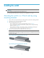
Installing the switch
WARNING!
Before installing or moving the switch, remove the power cord.
You can install an HP 1920 switch in a 19-inch rack, on a workbench, or on a wall.
Mounting the switch in a 19-inch rack by using
mounting brackets
1.
Wear an ESD wrist strap and make sure it makes good skin contact and is reliably grounded.
2.
Verify that the rack is securely grounded and is stable.
3.
Select mounting brackets for the switch.
{
{
{
4.
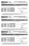
The HP 1920-8G switch uses Type-A mounting brackets, as shown in Figure 1.
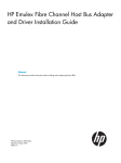
The HP 1920-8G-PoE+ (65W) and 1920-8G-PoE+ (180W) switches use Type-B mounting
brackets, as shown in Figure 2.
The HP 1920-16G, 1920-24G, 1920-24G-PoE+ (180W), 1920-24G-PoE+ (370W) and
1920-48G switches use Type-C mounting brackets, as shown in Figure 3.
Attach the mounting brackets to both sides of the chassis with screws.
NOTE:
Mounting brackets are used only for securing the switch to the rack. A rack shelf on the rack is used
to bear the switch weight.
Figure 1 Attaching Type-A mounting brackets to the switch
Figure 2 Attaching Type-B mounting brackets to the switch
4
Figure 3 Attaching Type-C mounting brackets to the switch
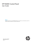
5.
Place the switch on a rack shelf in the rack. Push the switch in until the oval holes in the brackets
align with the mounting holes in the rack posts.
6.
Attach the mounting brackets to the rack posts with screws.
Figure 4 Attaching Type-A mounting brackets to the rack post
5
Figure 5 Attaching Type-B mounting brackets to the rack post
Figure 6 Attaching Type-C mounting brackets to the rack post
6
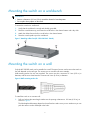
Mounting the switch on a workbench
IMPORTANT:
• Reserve a clearance of 10 cm (3.9 in) around the chassis for heat dissipation.
• Do not place heavy objects on the switch.
To mount the switch on a workbench:
1.
Verify that the workbench is sturdy and reliably grounded.
2.
Place the switch bottom up, and clean the round holes in the chassis bottom with a dry cloth.
3.
Attach the rubber feet to the four round holes in the chassis bottom.
4.
Place the switch upside up on the workbench.
Figure 7 Attaching rubber feet (HP 1920-24G-PoE+ Switch)
Mounting the switch on a wall
Only the HP 1920-8G switch can be installed on a wall. The type of screws used to mount the switch on
the wall depends on the wall type. This section uses a concrete wall as an example.
Wall-mounting anchor kits are user supplied. The screws must be a minimum of 3 mm (0.12 in) in
diameter, and the screw head must be a minimum of 6 mm (0.24 in) in diameter.
Figure 8 Wall-mounting anchor kit
To install the switch on a concrete wall:
1.
Drill two holes at the same height. Make sure the spacing in between is 160 mm (6.30 in), as
shown in Figure 9.
The hole depth and diameter depend on the wall anchors and screws you use. Make sure you can
push the anchors to their full depth in the holes.
7
Figure 9 Hole spacing
2.
Insert one wall anchor into each hole until the anchors are flush with the wall surface.
3.
Drive one screw into each wall anchor, and tighten the screws just enough to keep it secure in the
wall anchor.
Leave a minimum clearance of 1.5 mm (0.06 in) between the base of the screw head and the wall
anchor so the switch can hang on the screws securely.
Figure 10 Driving a screw into a wall anchor
4.
Align the two mounting holes in the switch chassis bottom with the two screws on the wall and
hang the switch.
Make sure the Ethernet ports are facing downwards and the chassis side panels are perpendicular
to the ground.
Figure 11 Wall mounting
(1) Mounting hole in the switch chassis bottom
8
Connecting cables
Connecting network cable
Use crossover cable or straight through cable to connect a PC or other network devices to the Ethernet
port of the switch.
Figure 12 Connecting network cable
Installing the SFP transceiver module and optical fibers
CAUTION:
• Hold the SFP transceiver module by its two sides when you install or remove the module. Do not touch
the golden finger of the module.
• Remove the optical fiber, if any, from a transceiver module before installing it.
To install an SFP transceiver module and optical fibers:
1.
Wear an ESD wrist strap and make sure it makes good skin contact and is reliably grounded.
2.
Pivot the clasp of the module up. Holding the module, gently push the module into the slot until it
has firm contact with the slot (when the top and bottom spring tabs catch in the slot).
3.
Remove protective sleeves from optical fibers, and the dust plug from the transceiver module.
4.
Connect the LC connectors of the optical fibers to the transceiver module.
NOTE:
Keep the protective sleeves for future use.
9
Figure 13 Installing the SFP transceiver module and optical fibers
Connecting the console cable
To connect a terminal (for example, a PC) to the switch:
1.
Wear an ESD wrist strap and make sure it makes good skin contact and is reliably grounded.
2.
Connect the DB-9 female connector of the console cable to the serial port of the PC.
3.
Connect the RJ-45 connector to the console port of the switch.
Figure 14 Connecting the console cable
NOTE:
To disconnect the console cable, remove the RJ-45 connector of the cable and then the DB-9 female
connector.
Connecting the AC power cord
1.
Wear an ESD wrist strap and make sure it makes good skin contact and is reliably grounded.
2.
Connect one end of the grounding cable to the grounding screw on the rear panel, and connect
the other end to the ground.
3.
Make sure the correct power source is used.
10
4.
Connect one end of the AC power cord to the AC power receptacle on the switch.
5.
Connect the other end of the AC power cord to the AC power outlet.
6.
Examine the power LED. If it is ON, the power connection is correct.
Figure 15 Connecting the AC power cord to the AC power receptacle
Connecting the DC power cord
IMPORTANT:
Make sure the DC power cord is shorter than 3 m (9.84 ft).
Only the HP 1920-24G-PoE+ (370W) supports DC RPS power.
If only the DC power cord is connected, the switch operates correctly when the DC input voltage is in the
range of –47 VDC to –57 VDC. If both AC and DC power cords are connected, the switch chooses the
power supply based on the DC input voltage, as shown in Table 4.
Table 4 Power supply selection criteria
DC input voltage
Power supply
–54 VDC to –57 VDC
DC
< –54 VDC
AC
To connect the DC power cord:
1.
Wear an ESD wrist strap and make sure it makes good skin contact and is reliably grounded.
2.
Connect one end of the grounding cable to the grounding screw on the rear panel, and connect
the other end to the ground.
3.
Insert the DC connector to the DC power receptacle.
If you cannot insert the connector into the receptacle, do not force it. Re-orient the connector and
try to insert it again.
4.
Use a flathead screwdriver to fasten screws on both sides of the connector.
5.
Connect the other end of the DC power cord to the RPS. Make sure the RPS is supplying a minimum
of 876 W power.
6.
View the RPS LED to verify that the DC power cord is installed correctly.
11
Figure 16 Connecting the DC power cord to the DC power receptacle
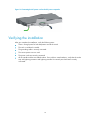
Verifying the installation
After you complete the installation, verify the following items:
•
There is enough space for heat dissipation around the switch.
•
The rack or workbench is stable.
•
The grounding cable is securely connected.
•
The correct power source is used.
•
The power cords are correctly connected.
•
All the interface cables are cabled indoors. If any cable is routed outdoors, verify that the socket
strip with lightning protection and lightning arresters for network ports have been correctly
connected.
12
Accessing the switch for the first time
Setting up the configuration environment
The first time you access the switch you must use a console cable to connect a console terminal, for
example, a PC, to the console port on the switch.
Figure 17 Connecting the console port to a terminal
Connecting the console cable
Console cable
A console cable is an 8-core shielded cable. It has a crimped RJ-45 connector at one end for connecting
to the console port of the switch, and a DB-9 female connector at the other end for connecting to the
serial port on the console terminal.
Figure 18 Console cable
A side
Pos.9
Main label
8
A
1
Pos.1
13
B side
B
Connection procedure
CAUTION:
The serial ports on PCs do not support hot swapping. To connect a PC to an operating switch, first connect
the PC end. To disconnect a PC from an operating switch, first disconnect the switch end.
To connect a terminal (for example, a PC) to the switch:
1.
Wear an ESD wrist strap and make sure it makes good skin contact and is reliably grounded.
2.
Connect the DB-9 female connector of the console cable to the serial port of the PC.
3.
Connect the RJ-45 connector to the console port of the switch.
Identify the mark on the console port and make sure you are connecting to the correct port.
Setting terminal parameters
To configure and manage the switch, you must run a terminal emulator program on the console terminal.
The following terminal settings are required:
•
Bits per second—38400.
•
Data bits—8.
•
Parity—None.
•
Stop bits—1.
•
Flow control—None.
•
Emulation—VT100.
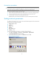
To set terminal parameters (for example, on a Windows XP HyperTerminal):
1.
Select Start > All Programs > Accessories > Communications > HyperTerminal.
The Connection Description dialog box appears.
2.
Enter the name of the new connection in the Name field and click OK.
Figure 19 Connection description
14
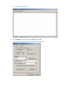
3.
Select the serial port to be used from the Connect using list, and click OK.
Figure 20 Setting the serial port used by the HyperTerminal connection
4.
Set Bits per second to 38400, Data bits to 8, Parity to None, Stop bits to 1, and Flow control to
None, and click OK.
Figure 21 Setting the serial port parameters
5.
Select File > Properties in the HyperTerminal window.
15
Figure 22 HyperTerminal window
6.
On the Settings tab, set the emulation to VT100 and click OK.
Figure 23 Setting terminal emulation in Switch Properties dialog box
16
Powering on the switch
Verification before power-on
Before powering on the switch, verify the following items:
•
The power cord is correctly connected.
•
The input power voltage meets the requirement of the switch.
•
The console cable is correctly connected.
•
The terminal (for example, a PC) has started, and its configuration parameters have been correctly
set.
Powering on the switch
Power on the switch (for example, an HP 1920-24G switch), and the following information is displayed:
Starting......
****************************************************************************
*
*
*
HP 1920-24G Switch JG924A BootWare, Version 1.09
*
*
*
****************************************************************************
Copyright (c) 2010-2014 Hewlett-Packard Development Company, L.P.
Compiled Date
: Mar 20 2014 17:00:53
CPU Type
: MIPS4kec
CPU L1 Cache
: 16KB
CPU Clock Speed
: 500MHz
Memory Type
: DDR3 SDRAM
Memory Size
: 128MB
Memory Speed
: 300MHz
BootWare Size
: 3MB
Flash Size
: 32MB
BootWare Validating...
Press Ctrl+B to enter extended boot menu...
Starting to get the main application file--flash:/ 1920-24G.bin!........
..............
The main application file is self-decompressing.............................
............................................................................
............................................................................
............................................................................
............................................................................
............................................................................
............................................................................
............................................................................
17
............................................................................
............................................................................
............................................................................
............................................................................
............................................................................
............................................................................
............................................................................
............................................................................
............................................................................
............................................................................
............................................................................
........................................................Done!
System application is starting...
User interface aux0 is available.
Press ENTER to get started.
Press Enter and the system displays the following prompt:
<Hp>
This prompt indicates that the switch is ready to configure.
18
Support and other resources
Contacting HP
For worldwide technical support information, see the HP support website:
http://www.hp.com/support
Before contacting HP, collect the following information:
•
Product model names and numbers
•
Technical support registration number (if applicable)
•
Product serial numbers
•
Error messages
•
Operating system type and revision level
•
Detailed questions
Subscription service
HP recommends that you register your product at the Subscriber's Choice for Business website:
http://www.hp.com/go/wwalerts
After registering, you will receive email notification of product enhancements, new driver versions,
firmware updates, and other product resources.
Related information
Documents
To find related documents, browse to the Manuals page of the HP Business Support Center website:
http://www.hp.com/support/manuals
•
For related documentation, navigate to the Networking section, and select a networking category.
•
For a complete list of acronyms and their definitions, see HP FlexNetwork Technology Acronyms.
Websites
•
HP.com http://www.hp.com
•
HP Networking http://www.hp.com/go/networking
•
HP manuals http://www.hp.com/support/manuals
•
HP download drivers and software http://www.hp.com/support/downloads
•
HP software depot http://www.software.hp.com
•
HP Education http://www.hp.com/learn
19
Conventions
This section describes the conventions used in this documentation set.
Command conventions
Convention
Description
Boldface
Bold text represents commands and keywords that you enter literally as shown.
Italic
Italic text represents arguments that you replace with actual values.
[]
Square brackets enclose syntax choices (keywords or arguments) that are optional.
{ x | y | ... }
Braces enclose a set of required syntax choices separated by vertical bars, from which
you select one.
[ x | y | ... ]
Square brackets enclose a set of optional syntax choices separated by vertical bars, from
which you select one or none.
{ x | y | ... } *
Asterisk-marked braces enclose a set of required syntax choices separated by vertical
bars, from which you select at least one.
[ x | y | ... ] *
Asterisk-marked square brackets enclose optional syntax choices separated by vertical
bars, from which you select one choice, multiple choices, or none.
&<1-n>
The argument or keyword and argument combination before the ampersand (&) sign can
be entered 1 to n times.
#
A line that starts with a pound (#) sign is comments.
GUI conventions
Convention
Description
Boldface
Window names, button names, field names, and menu items are in bold text. For
example, the New User window appears; click OK.
>
Multi-level menus are separated by angle brackets. For example, File > Create > Folder.
Convention
Description
Symbols
WARNING
An alert that calls attention to important information that if not understood or followed can
result in personal injury.
CAUTION
An alert that calls attention to important information that if not understood or followed can
result in data loss, data corruption, or damage to hardware or software.
IMPORTANT
An alert that calls attention to essential information.
NOTE
TIP
An alert that contains additional or supplementary information.
An alert that provides helpful information.
20
Network topology icons
Represents a generic network device, such as a router, switch, or firewall.
Represents a routing-capable device, such as a router or Layer 3 switch.
Represents a generic switch, such as a Layer 2 or Layer 3 switch, or a router that supports
Layer 2 forwarding and other Layer 2 features.
Represents an access controller, a unified wired-WLAN module, or the switching engine
on a unified wired-WLAN switch.
Represents an access point.
Represents a mesh access point.
Represents omnidirectional signals.
Represents directional signals.
Represents a security product, such as a firewall, UTM, multiservice security gateway, or
load-balancing device.
Represents a security card, such as a firewall, load-balancing, NetStream, SSL VPN, IPS,
or ACG card.
Port numbering in examples
The port numbers in this document are for illustration only and might be unavailable on your device.
21
Appendix A Chassis views and technical
specifications
Chassis views
1920-8G
Figure 24 1920-8G front panel
(1) 10/100/1000BASE-T copper ports
(2) 100/1000BASE-X SFP fiber ports
(3) Console port
(4) Fiber port LEDs
(5) Copper port LEDs
(6) Power LED
Figure 25 1920-8G rear panel
(1) Grounding screw
(2) AC power receptacle
(3) Security slot
1920-16G
Figure 26 1920-16G front panel
(1) 10/100/1000BASE-T copper ports
(2) 100/1000BASE-X SFP fiber ports
(3) Fiber port LEDs
(4) Copper port LEDs
(5) Power LED
(6) Console port
22
Figure 27 1920-16G rear panel
(1) Grounding screw
(2) AC power receptacle
1920-24G
Figure 28 1920-24G front panel
(1) 10/100/1000BASE-T copper ports
(2) 100/1000BASE-X SFP fiber ports
(3) Fiber port LEDs
(4) Copper port LEDs
(5) Power LED
(6) Console port
Figure 29 1920-24G rear panel
(1) Grounding screw
(2) AC power receptacle
1920-48G
Figure 30 1920-48G front panel
(1) 10/100/1000BASE-T copper ports
(2) 100/1000BASE-X SFP fiber ports
(3) Console port
(4) Power LED
23
Figure 31 1920-48G rear panel
(1) Grounding screw
(2) AC power receptacle
1920-8G-PoE+ (65W)
Figure 32 1920-8G-PoE+ (65W) front panel
(1) 10/100/1000BASE-T copper ports
(2) 100/1000BASE-X SFP fiber ports
(3) Console port
(4) Fiber port LEDs
(5) Copper port LEDs
(6) Power LED
Figure 33 1920-8G-PoE+ (65W) rear panel
(1) AC power receptacle
(2) Grounding screw
(3) Security slot
1920-8G-PoE+ (180W)
Figure 34 1920-8G-PoE+ (180W) front panel
(1) 10/100/1000BASE-T copper ports
(2) 100/1000BASE-X SFP fiber ports
(3) Console port
(4) Fiber port LEDs
(5) Copper port LEDs
(6) Power LED
24
Figure 35 1920-8G-PoE+ (180W) rear panel
1
2
3
(1) AC power receptacle
(2) Grounding screw
(3) Security slot
1920-24G-PoE+ (180W)
Figure 36 1920-24G-PoE+ (180W) front panel
(1) 10/100/1000BASE-T copper ports
(2) 100/1000BASE-X SFP fiber ports
(3) Fiber port LEDs
(4) Copper port LEDs
(5) Power LED
(6) Console port
Figure 37 1920-24G-PoE+ (180W) rear panel
(1) Grounding screw
(2) AC power receptacle
1920-24G-PoE+ (370W)
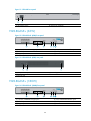
Figure 38 1920-24G-PoE+ (370W) front panel
(1) 10/100/1000BASE-T copper ports
(2) 100/1000BASE-X SFP fiber ports
(3) Fiber port LEDs
(4) Copper port LEDs
(5) Redundant power system (RPS) power LED
(6) Power LED
(7) Console port
25
Figure 39 1920-24G-PoE+ (370W) rear panel
(1) Grounding screw
(2) AC power receptacle
(3) DC power receptacle
Physical specifications
Chassis dimensions and weights
Chassis
Dimensions (H x W x D)
Maximum weight
1920-8G
44 x 266 x 162 mm (1.73 x 10.47 x 6.38 in)
1 kg (2.20 lb)
1920-16G
44 x 440 x 173 mm (1.73 x 17.32 x 6.81 in)
2.1 kg (4.63 lb)
1920-24G
44 x 440 x 173 mm (1.73 x 17.32 x 6.81 in)
2.2 kg (4.85 lb)
1920-8G-PoE+ (65W)
44 x 330 x 230 mm (1.73 x 12.99 x 9.06 in)
2.1 kg (4.63 lb)
1920-8G-PoE+ (180W)
44 x 330 x 230 mm (1.73 x 12.99 x 9.06 in)
2.5 kg (5.51 lb)
1920-24G-PoE+ (180W)
44 x 440 x 238 mm (1.73 x 17.32 x 9.37 in)
3.4 kg (7.50 lb)
1920-24G-PoE+ (370W)
44 x 440 x 260 mm (1.73 x 17.32 x 10.24 in)
4.0 kg (8.82 lb)
1920-48G
44 x 440 x 238 mm (1.73 x 17.32 x 9.37 in)
3.4 kg (7.50 lb)
Ports and interface card slots
Chassis
Console ports
10/100/1000Base-T
auto-sensing Ethernet
ports
100/1000Base-X SFP
ports
1920-8G
1
8
2
1920-16G
1
16
4
1920-24G
1
24
4
1920-8G-PoE+ (180W)
1
8, PoE+
2
1920-8G-PoE+ (65W)
1
8, PoE+
2
1920-24G-PoE+ (370W)
1
24, PoE+
4
1920-24G-PoE+ (180W)
1
24, PoE+
4
1920-48G
1
48
4
26
Environmental specifications
Chassis
Operating temperature
Relative humidity
All chassis
0°C to 40°C (32°F to 104°F)
5% to 95%, noncondensing
Power specifications
AC input voltage specifications
Chassis
Rated voltage range
All chassis
100 VAC to 240 VAC @ 50 Hz or 60 Hz
RPS DC input voltage specifications and RPS compatibility
Chassis
RPS input rated voltage range
1920-24G-PoE+ (370W)
–54 VDC to –57 VDC
Power consumption specifications for non-PoE switches
Chassis
Minimum power consumption
Maximum power consumption
1920-8G
4W
8.5 W
1920-16G
5.7 W
13 W
1920-24G
9.5 W
19 W
1920-48G
20 W
32 W
Power consumption specifications for PoE switches
Chassis
Maximum
PoE power
per port
Maximum
PoE ports at
full 30 W
output
Total PoE
output
Minimum
power
consumption
Maximum power
consumption
(including total PoE
output)
1920-8G-PoE+
(65W)
30 W
2
65 W
6W
94 W
1920-8G-PoE+
(180W)
30 W
6
180 W
11 W
230 W
1920-24G-PoE+
(180W)
30 W
6
180 W
18 W
235 W
27
Chassis
1920-24G-PoE
(370W)
Maximum
PoE power
per port
30 W
Maximum
PoE ports at
full 30 W
output
Total PoE
output
370 W at
AC input
12 at AC
input
24 at RPS DC
input
740 W at
RPS DC
input
Minimum
power
consumption
Maximum power
consumption
(including total PoE
output)
18.5 W at AC
input
474 W at AC input
17 W at RPS
DC input
Cooling system
Chassis
Fixed fans
1920-8G
1920-8G-PoE+ (65W)
N/A
1920-16G
1920-24G
1920-48G
1
1920-8G-PoE+ (180W)
2
1920-24G-PoE+ (180W)
1920-24G-PoE+ (370W)
3
28
834 W at RPS DC
input
Appendix B LEDs
Power LED
Table 5 Power LED description
Status
Description
Steady green
The switch is powered on and the power supply is operating correctly.
Flashing green
The switch is powered on and is performing the self-test.
Off
The switch is not powered on or the power supply is faulty.
Copper port LEDs
Link/ACT LEDs
Table 6 Link/ACT LED description
Status
Description
Steady yellow
A 10/100-Mbps link is present.
Flashing yellow
The port is receiving or sending data at 10/100 Mbps.
Steady green
A 1000-Mbps link is present.
Flashing green
The port is receiving or sending data at 1000 Mbps.
Off
No link is present.
PoE LEDs
Table 7 PoE LED description
Status
Description
Steady yellow
The port is supplying power correctly.
Flashing yellow
The port is supplying power incorrectly.
Off
The port is not supplying power.
Fiber port LEDs
Table 8 SFP port LED description
Status
Description
Steady yellow
A 100-Mbps link is present.
Flashing yellow
The port is receiving or sending data at 100 Mbps.
29
Status
Description
Steady green
A 1000-Mbps link is present.
Flashing green
The port is receiving or sending data at 1000 Mbps.
Off
No link is present.
RPS LED
Only the HP 1920-24G-PoE+ (370W) supports the RPS.
Table 9 RPS power LED description
Status
Description
Steady green
The RPS is supplying power correctly.
Off
No RPS is used or the RPS is supplying power incorrectly.
30
Appendix C Troubleshooting
Table 10 describes the troubleshooting methods for common issues that you might encounter while using
and managing the switch.
If a problem persists, contact HP Support.
Table 10 Troubleshooting methods
Symptom
Power LED off
LAN interface LED off
Troubleshooting method
1.
Verify that the correct power source is used and the power cords
are correctly connected.
2.
Verify that the power source side provides power supply correctly.
1.
Verify that the network cable is correctly connected to the network
port of the switch.
2.
Insert the two ends of a network cable into two network ports of the
switch. If the port LEDs are off, replace the network cable.
1.
Ping 127.0.0.1 to verify that TCP/IP has been installed.
2.
Ping the management IP address of the switch to verify that the
management PC is connected to the switch. If not, perform the
following check:
{
{
Unable to log in to the Web interface
of the HP 1920 switch
For local configuration, verify that the IP addresses of the
management PC and the switch are in the same subnet.
For remote configuration, verify that the route from the
management PC to the switch is reachable.
3.
Identify the LED status to verify that the cables are connected
correctly.
4.
Verify that the switch's port that connects to the management PC is
enabled and belongs to the management VLAN.
5.
Verify that the Web browser is not configured with proxy or dial-up
connection.
6.
Disable and then enable the local network after you complete local
network settings.
31