1
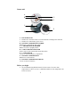
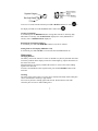
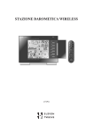
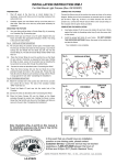
HONEYWELL
REMOTE UV SENSOR
for Professional Weather Station TE923W
TS704
USER MANUAL
Table of Contents
Introduction
Standard Package Contents
Sensor unit
Before you begin
Installation
Mounting
Operation
Maintenance
Troubleshooting
PRECAUTIONS
Specifications
FCC STATEMENT
DECLARATION OF CONFORMITY
STANDARD WARRANTY INFORMATION
2
3
3
4
4
5
6
6
7
8
8
8
9
9
10
Introduction
Thank you for selecting the Honeywell remote UV sensor TS704. This product is a part
of the Professional Weather Station TE923W. It measures UV (ultraviolet light) levels
and transmits data to a TE923WD (main display unit).
Note: In order to display the ultraviolet light levels, you must own a main display unit
(TE923WD) for the Professional Weather Station TE923W.
In this package you will find:
One Sensor Unit
One U-Shaped Sensor holder
One Circular Ground Stand
One Stake Base
One Wall-Mounting Base
Mounting Hardware
One User Manual
Standard Package Contents
Picture
Components
UV Sensor consists of:
Sensor Unit
U-Shaped Sensor holder
Circular Ground Stand
Stake Base
Wall-Mounting Base
Mounting hardware
3
Sensor unit
A
B
G
F
C
E
D
A. LED INDICATOR
• Flashes once when the remote UV sensor transmits a reading to the main unit
• Flashes twice when battery power is low
B. BATTERY COMPARTMENT SCREW
Holds battery compartment door in place
C. U-SHAPED SENSOR HOLDER
Holds UV sensor in upright position
D. CURCULAR GROUND STAND
Secures sensor in the sensor holder on the flat surface
E. UV SENSOR LID
Covers UV sensor and battery compartment
F. BATTERY COMPARTMENT
Holds two AA-size batteries
G. BATTERY COMPARTMENT DOOR
Covers two AA-size batteries
Before you begin
•
We recommend using alkaline batteries for the remote UV sensor when
temperatures are above 32°F (0°C)\ and lithium batteries when temperatures are
below 32°F (0°C).
4
•
•
•
•
•
•
•
Avoid using rechargeable batteries. (Rechargeable batteries cannot maintain
correct power requirements).
Insert batteries before first use, matching the polarity in the battery compartment
During an initial setup, place the main unit close to the remote UV sensor.
After reception is established (the remote UV readings will appear on the main
unit’s display), position the UV sensor and the main unit within the effective
transmission range of 328 feet (100 meters). Ideally it should be placed within
the line of sight of the main unit.
Transmission range may be affected by trees, metal structures and electronic
appliances.
The effective operating range may be influenced by the surrounding building
materials and how the receiver (main unit) and transmitter (UV sensor) are
positioned.
Place the remote UV sensor so that it faces the main unit (receiver), minimizing
obstructions such as doors, walls and furniture.
Installation
The Honeywell Remote UV sensor TS704 operates at 433MHz radio frequency, so no
wire installation is required between the main unit (receiver) and the remote UV sensor
(transmitter).
All data measured by the remote UV sensor is transmitted to the main unit wirelessly,
with the operating range of 328 feet (100 meters) in the open area.
Remote UV sensor must be placed outdoors to measure ultraviolet light levels.
To install it:
• Unscrew the lid on top of the UV sensor unit.
• Remove the screw from the battery compartment door with a small Phillips
screwdriver.
• Insert two 2 “AA” size 1.5V batteries (not included) matching the polarities
shown in the battery compartment.
• Replace the battery compartment door and secure the screw. The red light from
the LED indicator will flash once meaning the UV sensor works properly.
• Screw the UV sensor unit lid back.
• Press DOWN button either on the main unit control panel or handheld remote
control. The UV reading (usually 0.00) will appear in UV window of TE923W main
unit display, instead of “ - - -“.
Assembly
• Snap the U-shaped sensor holder onto the UV sensor unit side grooves.
• Insert the round end of the U-shaped holder into the one of the mounting
hardware pieces provided (ground, stake or wall).
5
Mounting
There are three different options available for mounting the UV sensor: ground stand,
stake and wall mount.
Ground:
• Insert the U-shaped sensor holder round end into the circular ground stand
opening, matching 2 round holes in the opening
• Secure the sensor in a location with a maximum sun exposure throughout the
day.
Stake:
• Snap the sharp stake end onto the metal bar and secure with the screws
provided.
• Insert the other end of the metal bar into the U-shaped sensor holder and secure
with the screws provided.
• Secure the sensor in a location with a maximum sun exposure throughout the
day.
Wall:
• Insert the wall mounting end into the metal bar and secure with the screws
provided.
• Snap the other end of the metal bar on to the U-shaped sensor holder and secure
with the screws provided.
• Secure the sensor in a location with a maximum sun exposure throughout the
day.
Placement tips:
The UV sensor should be mounted in the area free of sunlight shadows or reflections
from the nearby objects.
Operation
The current UV intensity is indicated in the UV window of the TE923W main unit
display. It is given in the numerical value and more intuitive display, by categorizing it
into the levels “LOW”, “MED”, HIGH”, V. HIGH” and EXTREME. It is also
represented by a comfort icon that corresponds to the different UV levels.
The main unit records daily and weekly maximum of the UV intensity. Values may be
displayed in MED/h or UVI. It also displays the remote UV sensor battery status.
6
To access UV mode from the main unit press UP or DOWN until the UV icon
the display will flash. From the handheld remote control: Press
on
.
Viewing UV Statistics
In UV Mode press the MEMORY button viewing either current UV intensity, daily
Maximum UV intensity with “DAILY MAX” displayed or weekly Maximum UV
intensity with a “WEEKLY MAX” displayed.
Resetting the UV Statistics Memory
In UV Mode, press and hold MEMORY button to reset all UV statistics.
Setting Units for UV Display (MED/h or UVI)
In UV Mode, press and hold SET to convert units between MED/h and UVI.
Maintenance
Changing Batteries
The battery status of the remote UV sensor is checked every hour by the main unit. If the
low battery indicator in the display section for UV data lights up, replace the batteries in
the remote UV sensor.
When the batteries are properly installed, the remote UV sensor will resume sending
signals to the main unit.
To enforce an immediate remote signals search, press and hold DOWN button on the
main unit.
Cleaning
The outer casing of the remote UV sensor can be cleaned with a damp cloth. Small parts
can be cleaned with a cotton tip or pipe-cleaner.
Never use any abrasive cleaning agents and solvents. Do not immerse units with
electronic parts in water or under running water.
7
Troubleshooting
Q: “The display shows dashes “---” for UV readings”
A: The display will show “- - -” when the wireless connection to remote UV sensor is lost
for 30 minutes.
Check and/or replace the batteries in UV sensor. Then press and hold DOWN button on
the main unit TE923DW or handheld remote control TS607 to enforce a search for the
remote signal.
If this does not work, check the wireless transmission path from the remote UV sensor to
the main unit and change its locations if necessary.
Although wireless signals can pass through solid objects and walls, the remote UV sensor
should ideally be within the line of sight of the main unit.
The following may be the cause of reception problems:
• The remote UV sensor and a main unit are too far from each other.
• The signal shielding materials, such as metal surfaces, concrete walls or dense
vegetation, are in the path of transmission.
• There is interference from the wireless devices (such as cordless phones, radio
headsets and baby listening devices) and electronic appliances.
PRECAUTIONS
This product is engineered to give you years of satisfactory service if handled carefully.
Here are a few precautions:
• Do not immerse the units in water.
• Do not clean the units with abrasive or corrosive materials. They may scratch
the plastic parts and corrode the electronic circuits.
• Do not subject the product to excessive force, shock, dust, temperature, or
humidity, which may result in malfunctions, shorter lifespan, damaged batteries,
and damaged parts.
• Do not tamper with the product’s internal components. Doing so will invalidate
the warranty and may cause damage. The product contains no user-serviceable
parts.
• Use only fresh batteries. Do not mix new and old batteries.
• Read the user's manual thoroughly before operating the product.
Specifications
Radio Frequency: 433 MHz
RF Reception range: 328 feet (100 m)
Ultraviolet light
Range: 0 UVI to 36UVI (15.4 MED/hour)
Resolution : 0.1UVI (0.1 MED/h)
8
Accuracy: 1UVI + 10%
Transmitting Interval: 300 seconds
Power: 2 x UM-3 or AA 1.5V battery
Battery life (alkaline): 2 years
Weight (without batteries): 2.78oz (79g)
Dimensions: 2.58(L) x 4.45(H) x 2.58(D) inches / 65.5(L) x 113(H) x 65.5(D) mm
FCC STATEMENT
This device complies with Part 15 of the FCC Rules. Operation is subject to the following
two conditions: (1) This device may not cause harmful interference, and (2) This device
must accept any interference received, including interference that may cause undesired
operation.
Warning: Changes or modification to this unit not expressly approved by the party
responsible for compliance could void the user’s authority to operate the equipment.
NOTE: This equipment had been tested and found to comply with the limits for a Class B
Digital device, pursuant to Part 15 of the FCC Rules. These limits are designed to provide
reasonable protection against harmful interference in a residential installation. This
equipment, installed and used in accordance with the instructions, may cause harmful
interference to radio communications.
There is no guarantee that interference will not occur in a particular installation. If this
equipment does cause harmful interference to radio or television reception, which can be
determined by turning the equipment off and on, the user is encouraged to improve or
correct turning the interference by one or more of the following measures:
•
•
•
•
Reorient or relocate the receiving antenna
Increase the separation between the equipment and receiver.
Connect the equipment to an outlet on a circuit different from that to which the
receiver is connected.
Consult the dealer or an experienced radio / TV technician for help.
DECLARATION OF CONFORMITY
We
Name: Hideki Electronics, Inc.
Address: 7865 SW Mohawk, Tualatin, OR 97062
Telephone No.: 1-503-612-8395
declare that the product
Product No.: TS704
Product Name: Remote UV Sensor for Professional Weather Station TE923W
9
Manufacturer: Hideki Electronics Ltd.
Address: Unit 2304-06, 23/F Riley House, 88 Lei Muk Road, Kwai Chung, New
Territories, Hong Kong
is in conformity with Part 15 of the FCC Rules. Operation is subject to the following two
conditions:
This device may not cause harmful interference.
This device must accept any interference received, including interference that may cause
undesired operation.
The information above is not to be used as a contact for support or sales. Please call
our customer service hotline (refer to the Standard Warranty Information) for all
injuries instead.
STANDARD WARRANTY INFORMATION
This product is warranted from manufacturing defects for one year from the date of retail
purchase. It does not cover damages or wear resulting from accident, misuse, abuse,
commercial use, or unauthorized adjustment and repair.
Note that online product registration is required to ensure valid warranty protection.
To register your product, go to our Company website at:
www.honeywellweatherstations.com. Click Online Product Registration under the
Customer Service menu.
Should you require assistance with this product and its operation, please contact our
Customer Service Hotline 1(866) 443 3543.
Please direct all returns to the place of the original purchase. Should this not be possible,
contact Hideki Customer Service Hotline for assistance and to obtain a Return
Merchandise Authorization (RMA). Returns without a return authorization will be
refused. Please retain your original receipt as you may be asked to provide a copy for
proof of purchase.
Hideki Electronics, Inc. reserves the right to repair or replace the product at our option.
Copyright (2005-2006) Hideki Electronics Inc. All Rights Reserved. The Honeywell
Trademark is used under license from Honeywell Intellectual Properties Inc.
Honeywell International Inc. makes no representations or warranties with respect to this
product.
All user manual contents and information are subject to change.
M1H704001-0506
10