1
Instructions – Parts List
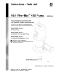
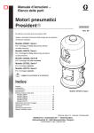
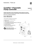
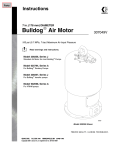
10:1 Fire–Ballr 425 Pump
309407E
EN
Low–pressure, medium volume pump used to transfer grease.
1800 psi (12.4 MPa, 124 bar) Maximum Working Pressure
180 psi (1.3 MPa, 13 bar) Maximum Air Inlet Pressure
Model No. 965124, Series B, Stubby length
Model No. 965129, Series B, 400 lb (180 Kg) drum length
For Closed Drum Mounting
Important Safety instructions.
Read all warnings and instructions in this manual.
Save these instructions.
WARNING
This pump is designed to be used only in pumping
non-corrosive and non-abrasive lubricants. Any
other use of the pump can cause unsafe operating
conditions and component rupture, which can result in fluid injection or other serious injury or fire or
explosion.
TI2146A
GRACO INC.ąP.O. BOX 1441ąMINNEAPOLIS, MNą55440-1441
Copyright 2002, Graco Inc. is registered to I.S. EN ISO 9001
Table of Contents
Warnings . . . . . . . . . . . . . . . . . . . . . . . . . . . . . . . . . . . . . . 2
Installation . . . . . . . . . . . . . . . . . . . . . . . . . . . . . . . . . . . . . 5
Operation . . . . . . . . . . . . . . . . . . . . . . . . . . . . . . . . . . . . . 7
Maintenance . . . . . . . . . . . . . . . . . . . . . . . . . . . . . . . . . . . 7
Troubleshooting . . . . . . . . . . . . . . . . . . . . . . . . . . . . . . . . 8
Service . . . . . . . . . . . . . . . . . . . . . . . . . . . . . . . . . . . . . . 10
Parts . . . . . . . . . . . . . . . . . . . . . . . . . . . . . . . . . . . . . . . .
Dimensions . . . . . . . . . . . . . . . . . . . . . . . . . . . . . . . . . . .
Technical Data . . . . . . . . . . . . . . . . . . . . . . . . . . . . . . . .
Graco Standard Warranty . . . . . . . . . . . . . . . . . . . . . .
Graco Information . . . . . . . . . . . . . . . . . . . . . . . . . . . . .
14
16
17
18
18
Symbols
Warning Symbol
Caution Symbol
WARNING
CAUTION
This symbol alerts you to the possibility of serious
injury or death if you do not follow the instructions.
This symbol alerts you to the possibility of damage to
or destruction of equipment if you do not follow the
instructions.
WARNING
SKIN INJECTION HAZARD
High–pressure fluid from dispense device, hose leaks, or ruptured components will pierce skin. This
may look like just a cut, but it is a serious injury that can result in amputation. Get immediate surgical treatment.
D Do not point the dispensing device at anyone or any part of the body.
D Do not put your hand over the end of the fluid outlet.
D Do not stop or deflect leaks with your hand, body, glove, or rag.
D Follow the Pressure Relief Procedure on page 7 before you clean, check, or service the
equipment.
D Tighten all fluid connections before operating the equipment.
D Check the hoses and couplings daily. Replace worn or damaged parts immediately.
MOVING PARTS HAZARD
Moving parts can pinch or amputate your fingers.
D Keep clear of all moving parts when starting or operating the pump.
D Before checking or servicing the equipment, follow the Pressure Relief Procedure on page 7 to
prevent the equipment from starting unexpectedly.
2
309407
WARNING
FIRE AND EXPLOSION HAZARD
Improper grounding, poor ventilation, open flames, or sparks can cause a hazardous condition and
result in a fire or explosion and serious injury.
D Ground the equipment and the object being dispensed to. Refer to Grounding on page 5.
D If there is any static sparking or you feel an electric shock while using this equipment, stop dispensing immediately. Do not use the equipment until you identify and correct the problem.
D Provide fresh air ventilation to avoid the buildup of flammable fumes from solvents or the fluid
being dispensed.
D Keep the dispensing area free of debris, including solvent, rags, and gasoline.
D Do not smoke in the dispensing area.
D Do not turn on or off any light switch in the area while dispensing if fumes are present.
D Never use 1.1.1–trichloroethane, methylene chloride, other halogenated hydrocarbon solvents, or
fluids containing such solvents in pressurized aluminum equipment. Such use could result in a
chemical reaction, with the possibility of explosion.
TOXIC FLUID HAZARD
Hazardous fluid or toxic fumes can cause serious injury or death if splashed in the eyes or on the skin,
inhaled, or swallowed.
D Know the specific hazards of the fluid you are using.
D Store hazardous fluid in an approved container. Dispose of hazardous fluid according to all local,
state, and national guidelines.
D Always wear protective eyewear, gloves, clothing, and respirator as recommended by the fluid and
solvent manufacturer.
D The air motor exhausts any fluids added to the input air.
D Graco does not manufacture or supply the reactive chemical components that may be used in this
equipment and is not responsible for injury or property loss, damage, expense, or claims (direct or
consequential) that arise from the use of such chemical components.
309407
3
WARNING
EQUIPMENT MISUSE HAZARD
Equipment misuse can cause the equipment to rupture or malfunction and result in serious injury.
D This equipment is for professional use only.
D Read all instruction manuals, tags, and labels before operating the equipment.
D Use the equipment only for its intended purpose. If you are not sure, call your Graco distributor.
D Do not alter or modify this equipment.
D Check equipment daily. Repair or replace worn or damaged parts immediately.
D Do not exceed the maximum working pressure stated on the equipment or in the Technical Data
for your equipment. Do not exceed the maximum working pressure of the lowest rated component
in your system.
D Use fluids and solvents which are compatible with the equipment wetted parts. Refer to the Technical Data section of all equipment manuals. Read the fluid and solvent manufacturer’s warnings.
D Handle hoses carefully. Do not pull on hoses to move equipment.
D Route hoses away from traffic areas, sharp edges, moving parts, and hot surfaces. Do not expose
Graco hoses to temperatures above 66_C (150_F) or below –40_C (–40_F).
D Wear hearing protection when operating this equipment.
D Do not move or lift pressurized equipment.
D Comply with all applicable local, state, and national fire, electrical, and safety regulations.
4
309407
Installation
NOTE: Reference numbers and letters in parentheses
in the text refer to the callouts in the figures and the
parts drawing.
NOTE: Always use Genuine Graco Parts and
Accessories, available from your Graco distributor.
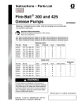
Grounding
WARNING
FIRE AND EXPLOSION HAZARD
Before operating the pump, ground the
system as explained below. Also read
the section FIRE OR EXPLOSION HAZARD on page 3.
D Pump: Use a ground wire and clamp as shown
below.
Z
D Dispensing valve: Ground through connection to a
properly grounded fluid hose and pump.
D Object being dispensed to: Follow your local code.
D Solvent pails used when flushing: Follow your local
code. Use only metal pails, which are conductive,
placed on a grounded surface. Do not place the pail
on a nonconductive surface, such as paper or
cardboard, which interrupts the grounding
continuity.
D To maintain grounding continuity when flushing or
relieving pressure, hold a metal part of the
dispensing gun firmly to the side of a grounded
metal pail, then trigger the gun to ground the pump.
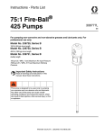
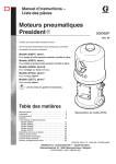
To ground the pump, remove the ground screw (Z)
and insert through the eye of the ring terminal at end of
ground wire (Y). Fasten the ground screw back onto
the pump and tighten securely. Connect the other end
of the ground wire to a true earth ground. See Fig. 1.
To order a ground wire and clamp, order Part No.
222011.
Y
Mounting the Pump
WARNING
Fig. 1
TI1052
D Air and fluid hoses: Use only electrically conductive
hoses.
D Air compressor: Follow manufacturer’s
recommendations.
Mount the pump securely so that it cannot move
around during operation. Failure to do so could
result in personal injury or equipment damage.
D Select a convenient location for the equipment to
ensure easy operator access to the pump air
controls, sufficient room to change supply
containers, and a secure mounting platform.
D If you are mounting the pump directly on the supply
tank, position the pump so its intake valve is no
more than 1 in. (25 mm) from the bottom of the
container. Mount the pump to the cover or other
suitable mounting device.
309407
5
Installation
Mount the pump to suit the type of installation planned.
Very heavy lubricants may require an inductor plate.
See page 16 for the mounting hole layout and
dimensions
WARNING
A bleed-type master air valve (B) is required to
shut off and relieve air pressure that may be
trapped in the air motor. Trapped air could cause
the pump to cycle unexpectedly and cause serious
bodily injury, including amputation.
Install the air line accessories in the approximate order
shown in the Typical Installation. Install a bleed-type
master air valve (B) within easy reach of the pump,
upstream from the air regulator. Install an air filter (C)
to remove harmful dirt and moisture from your
compressed air supply. For automatic air motor
lubrication, install an air line oiler (D) close to the pump
air inlet. Install an air regulator (E) to control pump
speed.
Be sure the air hose is properly sized to deliver an
adequate supply of air to the motor. Refer to the
Technical Data on page 17.
Connect a dispensing hose to the 3/4 npt(f) pump
outlet. Install an appropriate gun or dispensing valve to
the hose.
Ground the pump as explained on page 5.
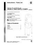
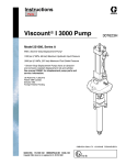
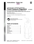
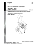
Typical Installation
Key
A
B
C
D
E
F
H
J
K
L
Grounded Air Line
Bleed-type Master Air Valve
Air Filter
Air Line Oiler
Air Regulator
Grounded Dispensing Hose
Elevator Assy. 241663
Ground Wire
Follow Plate 223701
Drum Cover 200326
A
C
D
J
E
B
F
L
K
H
TI2371A
Fig. 2
6
309407
Operation
WARNING
D This pump is designed to be used ONLY in
pumping non-corrosive and non-abrasive lubricants and greases. Any other use of this pump
can cause unsafe operating conditions and
result in component rupture, fire, or explosion,
which can can cause serious bodily injury,
including injection.
D Moving parts can pinch or amputate your fingers or other body parts. When the pump is
operating, the priming piston (located at the
pump intake) and the air motor piston (located
behind the air motor plates) move. NEVER
Operate the pump with the air motor plates
removed, and keep your fingers and hands
away from the priming piston.
Pressure Relief Procedure
WARNING
SKIN INJECTION HAZARD
Fluid under high pressure can be injected through the skin and cause
serious injury. To reduce the risk of an
injury from injection, splashing fluid, or moving
parts, follow the Pressure Relief Procedure
whenever you
D
D
D
D
Are instructed to relieve the pressure
Stop dispensing
Check or service any of the system equipment
Install or clean the dispensing nozzles
Startup and Adjustment
Open the bleed-type master air valve. Open the
dispensing valve, and slowly open the air regulator
until the pump is running smoothly. After all the air is
purged, close the dispensing valve. The pump will
start and stop as the valve is opened and closed.
CAUTION
Never allow the pump to run dry of the fluid being
pumped. A dry pump quickly accelerates to a high
speed and may damage itself. If your pump accelerates quickly or is running too fast, stop it immediately
and check the fluid supply. If the supply container is
empty and air has been pumped into the lines, prime
the pump and lines with fluid, or flush the pump and
leave it filled with a compatible solvent. Be sure to
eliminate all air from the fluid system.
Use the air regulator (E) to control the pump speed
and fluid pressure. See Fig. 2. Always use the lowest
pressure necessary to obtain the desired results.
When you are finished using the pump for the day,
always follow the Pressure Relief Procedure at left.
Maintenance
The Accessory air line oiler (D) provides automatic air
motor lubrication. For daily manual lubrication,
disconnect the air hose, place about 15 drops of light
machine oil in the air inlet, reconnect the hose, and
turn on the air supply to blow oil into the motor.
1. Close the air regulators.
2. Close the supply pump’s bleed-type master air
valve (required in this system).
3. Open the dispensing valve until pressure is fully
relieved.
If you suspect that the dispensing valve, extension, or
grease fitting coupler is clogged, or that pressure has
not been fully relieved after following the steps above,
VERY SLOWLY loosen the coupler or hose end
coupling and relieve pressure gradually, then loosen
completely, then clear the clog.
309407
7
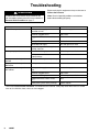
Troubleshooting
WARNING
To reduce the risk of serious injury whenever you
are instructed to relieve pressure, always follow the
Pressure Relief Procedure on page 7.
Before servicing this equipment always make sure to
Relieve the Pressure.
Note: Check all possible problems and solutions
before disassembling the pump.
Problem
Cause
Solution
Pump fails to operate.
Inadequate air supply pressure or
restricted air lines
Increase air supply; clear
Closed or clogged valves
Open; clean
Clogged fluid lines, hoses, valves,
etc.
Clear*
Damaged air motor
Service air motor
Exhausted fluid supply
Refill and reprime, or flush
Continuous air exhaust
Worn or damaged air motor gasket,
packing, seal, etc.
Service air motor
Erratic pump
p p operation
p
Exhausted fluid supply
Refill and reprime, or flush
Held open or worn intake valve or
piston packings
Clear; service
Pump operates, but output low on
upstroke
Held open or worn piston or packings
Clear; service
Pump operates, but output low on
downstroke
Held open or worn intake valve
Clear; service
Pump operates, but output low on
both strokes
Inadequate air supply or restricted air
lines
Increase air supply; clear
Closed or clogged valves
Open; clean
Exhausted fluid supply
Refill and reprime, or flush
Clogged fluid lines, hoses, valves,
etc.
Clear*
Loose packing nut or worn packings
Tighten; replace
* Follow the Pressure Relief Procedure, and disconnect the fluid line. If the pump starts when the air is turned
back on, the fluid line, hose, valve, etc. was clogged.
8
309407
Notes
309407
9
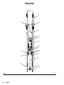
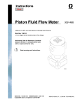
Service
2
12
31
3
4
14
15
16
5
11
30
7
6
8
25
9
10
TI2148A
Fig. 3
10
309407
Service
Displacement Pump Repair
WARNING
To reduce the risk of serious injury whenever you
are instructed to relieve pressure, always follow the
Pressure Relief Procedure on page 7.
8. Remove washers (35*), spreaders (34*), cup
packings (36*), o–ring (33*), and cup spacer (20)
from the piston housing (16).
9. Clean and inspect all the parts.
Reassembly
Before you start:
D To reduce down time, be sure you have all
necessary repair parts available.
D Repair Kit 237498 is available. If you have a repair
kit, use all the new parts for the best results. Parts
included in the kit are marked with an asterisk (*).
D When cleaning parts, use a compatible solvent.
Inspect parts for wear or damage and replace as
necessary. Scoring or irregular surfaces on the
priming rod (8) or polished inner wall of the riser
tube (2) causes premature packing wear and
leaking. Check these parts by rubbing a finger on
the surface and by holding the parts up to the light
at a slight angle.
Use light, waterproof grease wherever grease is
mentioned.
Disassembly
1. Follow the Pressure Relief Procedure on page
7.
2. Remove nut (10) and priming plate (9) from
priming rod (8).
3. Unscrew the foot valve housing (7) from cylinder
(2).
NOTE: Poppet check (6) foot valve packings and
bearings (5) slide off priming rod (8) when
removing foot valve housing.
1. Reassemble the piston, using all the new parts
from the kit and any other new parts needed. Oil
the leather cup packings (36*) first. Then assemble
the parts on the piston housing (16) in this order:
backup washer (35*), spreader (34*), leather
packing (36*), cup spacer (20) with new o–ring
(33*) installed in it, another leather packing (36*),
spreader (34*), and backup washer (35*).
NOTE: To replace the throat packings, follow the
procedure given in your separate air motor manual
(306982) before continuing with the procedure.
2. Screw the piston assembly onto the connecting
rod (3) and adjust the ball travel as instructed in
Check Valve Adjustment on page 12. Tighten the
locknut (4).
3. Check the o–ring (13) in the pump base and
replace it, if necessary.
4. Lubricate the piston packings and the inner wall at
the top of the riser tube (2). Wrap the packings
with with a guide collar made of 1/64 in. maximum
thickness shim stock or metal sheeting. Using a
turning motion, work the first leather packing into
the riser tube. Remove the guide collar and push
the riser tube up and screw it into the base. Torque
the tube to 100–150 ft.–lb. (135–204 N–m).
5. Slide bearing (5) onto priming rod (8) with the step
side facing the bottom of the pump.
6. Insert foot valve packings (30) into poppet check
(6) replace if necessary.
4. Unscrew bearing (5) from foot valve (7).
5. Remove the poppet check (6) and inspect foot
valve packings (30).
6. Unscrew riser tube (2) from pump base. Clean the
tube and inspect it for wear by holding it up to a
light at a slight angle. If you see wavy lines or
scratches where the piston travels, replace the
tube as it will not seal well with the new piston
packings and the pump will perform poorly.
7. Loosen the lock nut (4) and unscrew the valve
housing (14) from the connecting rod (3), unscrew
valve housing (14) from piston housing (16).
7. Slide poppet check containing foot valve packings
onto priming rod (8) with beveled edge facing the
bottom of the pump.
8. Slide foot valve over poppet check and screw
bearing (5) into the foot valve (7).
9. Push foot valve up to the riser tube.
10. Inspect o–ring (11) for damage and replace if
necessary.
11. Screw foot valve (7) onto riser tube (2).
309407
11
Service
12. Slide priming plate (9) (beveled edge up) onto
priming rod (8). Screw nut (10) onto priming rod
and tighten.
Check Valve Adjustment
13. Reconnect the pump’s ground wire to a true earth
ground.
To change the piston ball travel, loosen the locknut (4).
Turn the piston valve housing (14) counterclockwise to
increase and clockwise to decrease. Medium viscosity
fluids should have a 3/16 in. (5 mm) ball travel.
Decreasing the ball travel minimizes surging at stroke
changeover; however, too short of ball travel restricts
the flow and slows down the pump.
12
309407
This pump has an adjustable piston ball check.
Notes
309407
13
Parts
16
1
8
2
Packing, vee*
13
Spacer*
12
3
31
4
14
5
30
15
6
35*
11
34*
36*
7
33*
20
36*
9
34*
10
35*
TI2147A
14
309407
Parts
Model 965124, Series B
stubby length
Model 965129, Series B
400 lb. (180 Kg) drum length
Ref
No.
Part No.
1{
2
183010
160917
3
4
5
6
7
8
9
10
11
12
13
14
15
16
20
624936
624952
100111
624943
624938
624935
624937
624939
100077
156633
100103
156641
624941
100279
624942
158857
Description
AIR MOTOR
CYLINDER, pump, displacement
(model 965124 only)
CYLINDER, pump, displacement
(model 965129 only)
ROD, connecting (for 965124)
ROD, connecting (for 965129)
NUT
BEARING, rod guide, 10:1 shovel
POPPET, foot valve
VALVE, foot
ROD, priming
PLATE, priming; aluminum
NUT, hex
O-RING
PIN, cotter
O-RING
HOUSING, valve
BALL, metallic
HOUSING, valve piston
SPACER, cup
Qty.
1
Ref
No.
Part No.
Description
30
31
603778
222308
33*
34*
35*
36*
154662
171590
171594
158402
PACKING, foot valve
ADAPTER, bung; 2 in. npt
(model 965129 only)
O-RING
SPREADER, cup
WASHER, piston
CUP; leather
1
1
1
1
1
1
1
1
1
1
1
1
1
1
1
1
1
1
*
{
Qty.
2
1
1
2
2
2
These parts are included in Repair Kit 237498, which may
be purchased separately.
See Graco Manual 306982 to order replacement air motor
parts. Air motor 205647 is identical to the one on 965124
and 965129 with the following exceptions:
205647
Ref
No.
Part No.
Description
32
34
36
53
54
CYLINDER, motor, air
BASE, motor, air
PLATE, identification
SCREW, ground
NO WASHER, tab
15E954
15F982
15E555
116343
omitted
309407
15
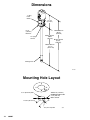
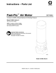
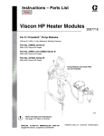
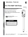
Dimensions
1” npt(f)
Fluid
Outlet
14 .6 in.
(371 mm)
6.5 in.
(165 mm)
Diameter
1/2 npt(f)
Air Inlet
Model 965124
28.5 in.
(724 mm)
Model 965124
13.9 in.
(353 mm)
Model 965129
50.8 in.
1290 mm)
Model 965129
37.3 in.
(947.4 mm)
Priming Piston
TI2146A
Mounting Hole Layout
3 1/4” (82.6 mm) DIA.
2–3/32” (53.18 mm)
TWO 5/16” (7.94 mm)
DIAMETER HOLES ON
4 1/4” (108 mm)
BOLT CIRCLE
45o
7/8” (22.2 mm) DIA.
16
309407
06337
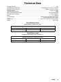
Technical Data
Fluid pressure ratio . . . . . . . . . . . . . . . . . . . . . . . . . . . . . . . . . . . . . . . . . . . . . . . . . . . . . . . . . . . . . . . . . . . . . . . . . . . . . . . 10:1
Air pressure operating range . . . . . . . . . . . . . . . . . . . . . . . . . . . . . . . . . . . . . . . . . . 40–180 psi (0.3–1.2 MPa, 3–12.4 bar)
Maximum working pressure . . . . . . . . . . . . . . . . . . . . . . . . . . . . . . . . . . . . . . . . . . . . . . . . . . 1800 psi (12.4 MPa, 124 bar)
Maximum delivery . . . . . . . . . . . . . . . . . . . . . . . . . . . . . . . . . . . . . . . . . . . . . . . . . . . . . . . . . . . . . . . . . . . . 5.2 gpm (19.7 lpm)
Cycles per gallon (per liter) . . . . . . . . . . . . . . . . . . . . . . . . . . . . . . . . . . . . . . . . . . . . . . . . . . . . . . . . . . . . . . . . . . . . . . . 20 (6)
Max. recommended pump speed . . . . . . . . . . . . . . . . . . . . . . . . . . . . . . . . . . . . . . . . . . . . . . . . . . . . . 60 cycles per minute
Air motor effective diameter . . . . . . . . . . . . . . . . . . . . . . . . . . . . . . . . . . . . . . . . . . . . . . . . . . . . . . . . . . . . . 4.25 in (108 mm)
Stroke . . . . . . . . . . . . . . . . . . . . . . . . . . . . . . . . . . . . . . . . . . . . . . . . . . . . . . . . . . . . . . . . . . . . . . . . . . . . . . . . . 4 in. (102 mm)
Air consumption . . . . . . . . . . . . . . . . . . . . . . . . . . . . . . . . . . . . . . . . . . . . . . . . . . . . approx. 13 cfm per gallon (6 m#/hr/liter)
of fluid at 100 psi (0.7 MPa, 7 bar)
Wetted parts . . . . . . . . . . . . . . . . . . . . . . . . . . . . . . . . . . . . . . . . . . . . . . . . . . . . . . steel, brass, aluminum, leather, Buna–N
Weight . . . . . . . . . . . . . . . . . . . . . . . . . . . . . . . . . . . . . . . . . . . . . . . . . . . . . . . . . . . . . . . . . . . . . . . . . . . . . . . . . . . 38 lb (17 kg)
Sound Pressure Level
(measured at 1 meter from unit)
Input Air Pressures at 15 cycles per minute
40 psi (0.28 MPa, 2.8 bar)
70 psi (0.48 MPa, 4.8 bar)
100 psi (0.7 MPa, 7 bar)
73.6 dB(A)
78.34 dB(A)
80.85 dB(A)
Sound Power Level
(tested in accordance with ISO 9614–2)
Input Air Pressures at 15 cycles per minute
40 psi (0.28 MPa, 2.8 bar)
70 psi (0.48 MPa, 4.8 bar)
100 psi (0.7 MPa, 7 bar)
87.4 dB(A)
92.09 dB(A)
94.62 dB(A)
309407
17
Graco Standard Warranty
Graco warrants all equipment manufactured by Graco and bearing its name to be free from defects in material and workmanship on the
date of sale to the original purchaser for use. With the exception of any special, extended, or limited warranty published by Graco,
Graco will, for a period of twelve months from the date of sale, repair or replace any part of the equipment determined by Graco to be
defective. This warranty applies only when the equipment is installed, operated and maintained in accordance with Graco’s written
recommendations.
This warranty does not cover, and Graco shall not be liable for general wear and tear, or any malfunction, damage or wear caused by
faulty installation, misapplication, abrasion, corrosion, inadequate or improper maintenance, negligence, accident, tampering, or
substitution of non-Graco component parts. Nor shall Graco be liable for malfunction, damage or wear caused by the incompatibility of
Graco equipment with structures, accessories, equipment or materials not supplied by Graco, or the improper design, manufacture,
installation, operation or maintenance of structures, accessories, equipment or materials not supplied by Graco.
This warranty is conditioned upon the prepaid return of the equipment claimed to be defective to an authorized Graco distributor for
verification of the claimed defect. If the claimed defect is verified, Graco will repair or replace free of charge any defective parts. The
equipment will be returned to the original purchaser transportation prepaid. If inspection of the equipment does not disclose any defect
in material or workmanship, repairs will be made at a reasonable charge, which charges may include the costs of parts, labor, and
transportation.
THIS WARRANTY IS EXCLUSIVE, AND IS IN LIEU OF ANY OTHER WARRANTIES, EXPRESS OR IMPLIED, INCLUDING BUT
NOT LIMITED TO WARRANTY OF MERCHANTABILITY OR WARRANTY OF FITNESS FOR A PARTICULAR PURPOSE.
Graco’s sole obligation and buyer’s sole remedy for any breach of warranty shall be as set forth above. The buyer agrees that no other
remedy (including, but not limited to, incidental or consequential damages for lost profits, lost sales, injury to person or property, or any
other incidental or consequential loss) shall be available. Any action for breach of warranty must be brought within two (2) years of the
date of sale.
Graco makes no warranty, and disclaims all implied warranties of merchantability and fitness for a particular purpose in connection
with accessories, equipment, materials or components sold but not manufactured by Graco. These items sold, but not manufactured
by Graco (such as electric motors, switches, hose, etc.), are subject to the warranty, if any, of their manufacturer. Graco will provide
purchaser with reasonable assistance in making any claim for breach of these warranties.
In no event will Graco be liable for indirect, incidental, special or consequential damages resulting from Graco supplying equipment
hereunder, or the furnishing, performance, or use of any products or other goods sold hereto, whether due to a breach of contract,
breach of warranty, the negligence of Graco, or otherwise.
FOR GRACO CANADA CUSTOMERS
The parties acknowledge that they have required that the present document, as well as all documents, notices and legal proceedings
entered into, given or instituted pursuant hereto or relating directly or indirectly hereto, be drawn up in English. Les parties
reconnaissent avoir convenu que la rédaction du présente document sera en Anglais, ainsi que tous documents, avis et procédures
judiciaires exécutés, donnés ou intentés à la suite de ou en rapport, directement ou indirectement, avec les procedures concernées.
Graco Information
TO PLACE AN ORDER, contact your Graco distributor, or call one of the following numbers
to identify the distributor closest to you:
1–800–533–9655 Toll Free
612–623–6928
612–378–3590 Fax
All written and visual data contained in this document reflects the latest product information available at the time of publication.
Graco reserves the right to make changes at any time without notice.
This manual contains English. MM 309407
Graco Headquarters: Minneapolis
International Offices: Belgium, Korea, China, Japan
GRACO INC.
P.O. BOX 1441
MINNEAPOLIS, MN
www.graco.com
09/2002, Revised 10/2011
18
309407
55440–1441