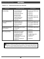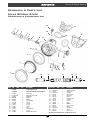
1
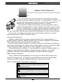
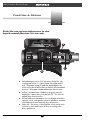
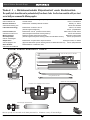
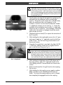
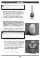
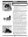
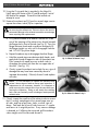
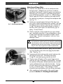
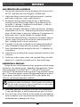
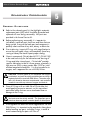
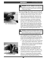
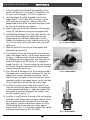
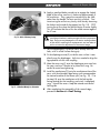
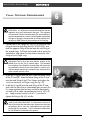
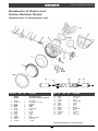
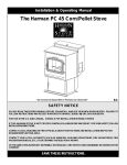
Atlas & Yukon
(Part Numbers GRXXX & )
Second Stage
SERVICE & REPAIR
GUIDE
Contents
Introduction ............................................................................ 3
About This Manual .........................................................................3
Scheduled Service ....................................................................................... 3
EAN/ Nitrox Service .................................................................................... 3
Use of Warnings, Cautions, & Notes ........................................................ 3
Function & Design ..........................................................................4
Section 1 – Facility Requirements ......................................... 5
Table 1 – Recommended Equipment and Suppliers ......................6
Section 2 – Preliminary Inspection ....................................... 7
External Inspection .......................................................................7
Immersion / Leak Test .....................................................................7
Section 3 – Disassembly Procedures .................................... 8
General Guidelines ........................................................................8
Section 4 – Cleaning Procedures ....................................... 14
Acidic Cleaning Procedure ......................................................... 14
EAN/Nitrox Cleaning Procedure ............................................... 17
Section 5 – Reassembly Procedures ................................... 24
General Guidelines ..................................................................... 24
Section 6 – Final Testing Procedures ................................ 28
Table 2 – Troubleshooting Guide ........................................ 32
Schematic & Parts List – Atlas Second Stage................... 33
Schematic & Parts List – Yukon Second Stage .................. 35
Service & Repair Manual
About This Manual
Introduction
As a service technician, you are entrusted with maintaining your customer’s
equipment to the same standards with which it was manufactured. At Genesis, we
are committed to providing you with the tools you will need to accomplish this
important task, including the information provided in this manual.
Possession of this manual, however, does not constitute an offer by Genesis
Scuba to sell component parts, nor does it qualify you to perform service or repair
for Genesis Scuba products. In order to purchase spare parts or perform service
and repair, you must be directly employed by an Authorized Genesis Dealer. It is
also your responsibility to obtain factory authorized training through your Genesis Scuba distributor.
If you are ever unsure about how to perform any of the procedures outlined in this manual,
please contact Genesis Scuba for technical assistance.
Scheduled Service
Regulators should be given the same care and maintenance as life support equipment. It is
therefore important to perform scheduled overhaul service for the entire regulator (first and second
stages) at least once every year with normal or infrequent use.
A unit that receives heavy or frequent use, however, should be serviced at least twice each year or more often - depending on the conditions of use and the manner in which it is maintained. (Refer
to the maintenance procedures outlined in the Genesis Regulator Owner’s Manual.).
When performing service, whether it is a routine overhaul or a repair of a specific problem, it is
important to understand how the regulator is designed and how it operates. An illustrated
explanation of the Atlas/Yukon second stage design is provided on the following page.
EAN/ Nitrox Service
Genesis regulators can be upgraded for use with oxygen enriched air (EAN/ Nitrox) not to
exceed 40% oxygen content. This upgrade must be performed in conjunction with a complete
overhaul, and includes a special cleaning procedure that is outlined in this manual.
Use of Warnings, Cautions, & Notes
WARNING indicates a procedure or situation that may
result in serious injury or death if instructions are not
followed correctly.
CAUTION indicates any situation or technique that will
result in potential damage to the product, or render the
product unsafe if instructions are not followed correctly.
NOTE is used to emphasize important points, tips, and
reminders.
3
Copyright ©2001 Liberty Group
Atlas & Yukon Second Stage
Function & Design
Introduction
The Atlas/Yukon second stage features a high performance, low volume
design with a mechanically balanced valve. Here's how it works:
3
2
1
4
Intermediate pressure air (140 psi) enters through the inlet
coupling and orifice (1), where it meets the poppet and LP
seat. The poppet spring (2) holds the poppet against the
orifice with a pre-set tension that counteracts the intermediate
pressure. The poppet is balanced between the two forces.
▼ Airflow is actuated upon inhalation or purging, when the
diaphragm is drawn down over the lever (3). This pulls the
poppet away from the orifice.
▼ Air and water are channeled to flow out through the exhaust
valve (4), which is designed to minimize exhalation resistance
while keeping the case internally dry in all positions.
▼ (Atlas only - not shown) A dive/pre-dive switch can be set to
minimize or boost peak venturi airflow, according to the
diver's preference.
▼
Copyright ©2001 Liberty Group
4
Service & Repair Manual
1
Facility Requirements
s e c t i o n
The service facility is perhaps the most important asset of
any professional dive store. It should be clean and well
lighted, and stocked with a complete inventory of parts and
manufacturer's specialty tools for the products your store sells.
As a minimum requirement, your service facility should be
equipped with the following items:
❏ Ultrasonic Cleaner – Select the right size model that can
keep up with the volume of regulators that your store services.
A built in timer and heater will help control the cleaning time
and temperature of the solution, since most solutions work best
when heated.
❏
Bench Mounted Vise – A vise is sometimes needed to hold
the regulator secure – especially when removing the first stage
yoke retainer. Special care must be taken, however, to avoid
damage that can result from improper use of this tool. Be sure
to follow the instructions provided in this manual.
❏
Magnification Lamp – Strong lighting and magnification are
essential requirements for performing a thorough parts inspection - especially when locating the cause of a small leak.
❏
Quality Wrenches & Sockets – When working with chrome
plated brass parts, it is especially critical to use the correct size
wrench and to ensure that it fits properly over the part. The use
of an adjustable wrench is very likely to cause damage to your
customer's regulator, and should be strictly avoided at all times.
❏
Calibrated Inch-Pound Torque Wrench – It is important to
follow the manufacturer's torque values whenever they are
specified, in order to avoid overtightening or under-tightening a
part. This is especially important for smaller parts and fittings,
when overtightening can easily damage the part.
❏
Calibrated Foot-Pound Torque Wrench – Torque
wrenches that can be set for both inch-pound and foot-pound
measurements generally tend to be less accurate than wrenches
that are designed to measure torque within a specific range.
❏
Manufacturer's Specialty Tools – Specialty tools are
critically important to performing each step of disassembly and
reassembly according to each manufacturer's procedures.
Genesis specialty tools that are required to perform service for
the Atlas and Yukon second stages are pictured on the following
page.
5
Copyright ©2001 Liberty Group
Atlas & Yukon Second Stage
Table 1 – Recommended Equipment and Suppliers
The specialty tools shown below can be purchased directly from Genesis Scuba. For other items needed to outfit your store's
service facility, we recommend the following suppliers:
Peter Built Co.
www.scubatools.com
Manufacturer of custom designed specialty tools
and test fixtures
Galion, OH 44833
Phone: 419-468-2212
Branson Ultrasonics
www.bransoncleaning.com
Manufacturer of tabletop ultrasonic cleaners
Danbury, CT 06813
Phone: 203-796-2298
Lubrication Technology
Manufacturer of Christo-Lube 111
(Genesis approved lubricant)
Lawrence Factor, Inc.
www.lawrence-factor.com
Manufacturer of LFW™ (Lawrence Factor Wash)
(Genesis approved acid bath cleaning solution)
Modern Chemical
Ohio Corporation
www.a1.com/bluegold
Distributor of Blue Gold Aqueous Cleaner
(Genesis approved aqueous cleaning solution for EAN/ Nitrox Service)
Simple Green
www.simplegreen.com
Manufacturer of Crystal Green Aqueous Cleaner
Huntington Harbor, CA 92649
(Approved alternative aqueous cleaning solution for EAN/ Nitrox Service)
Phone: (800) 228-0709
Sears Roebuck
www.sears.com/craftsman
Retail distributor of Craftsman® tools
Jackson, OH 45640
Phone: (740)286-2644
Miami Lakes, Florida 33014
Phone: 305-430-0550
Batesville, Indiana 47006
Phone: (812) 934-5915
Atlas/ Yukon Specialty Tools
Select Tool Kit (5 pcs) # 11-090-500
150
125 100 175
120
80
100
60
75
IP RANGE
125-150 PSI
260 2.0 x 50
200
140
225
IP RANGE
125-150 PSI
160
40
50
260 3.5 x 60
250
PSI
180
275
PSI
25
20
USE NO OIL
USE NO OIL
0
300
200
PETER BUILT
PETERinBUILT
CO.
"Quality
the making"
"Quality
in the making"
(419) 468-2212
(419) 468-2212
O-ring Tool Set #10-102Intermediate Pressure
Test Gauge, #20-510-100
Genesis Rim Clamp # 20-680-200
Dual Drive In-Line Adjusting Tool # 20-500-200
Genesis Poppet Tool Kit #20-640-
Genesis specialty tools are made in the USA by Peter Built Co. Illustrations courtesy of Peter Wolfinger.
Copyright ©2001 Liberty Group
6
Service & Repair Manual
2
Preliminary Inspection
s e c t i o n
External Inspection
1. Closely examine the conical filter of the first stage to check
for any signs that contaminants have entered the system,
including sea water, rust, or aluminum oxide.
NOTE: A green discoloration positively indicates that moisture has entered the regulator, and internal corrosion may
have occurred. Other types of discoloration may indicate
that the regulator has been used with a corroded cylinder.
Advise the customer of this, and the possible need to obtain
service for their cylinder.
2. Slide back the hose protector(s) to inspect the condition of
the LP hose at its fittings and along its length. Check
closely for any signs of blistering or abrasion, or corrosion
of the fittings.
3. Inspect the condition of the mouthpiece to check for torn
bite tabs, holes, or deterioration.
Immersion / Leak Test
1. Check to ensure that the regulator is fully assembled and
connected to a first stage, and that there are no open ports
or hoses. Connect the first stage to a cylinder that is filled
with 3,000 psi, and open the cylinder valve to pressurize
the regulator.
2. If leakage cannot be heard, or if the source of leakage
detected audibly is not obvious, immerse the second stage
in fresh water to check further for any signs of air leakage
through the mouthpiece and at the hose fitting.
3. Note the source of any leakage found and refer to Table 2
- Troubleshooting to determine its possible cause.
4. Close the cylinder valve and depress the second stage
purge cover to depressurize the regulator.
▼ After completing the Preliminary Inspection, proceed to
Section 3 – Disassembly
7
Copyright ©2001 Liberty Group
Atlas & Yukon Second Stage
3
Disassembly Procedures
s e c t i o n
General Guidelines
▼
Prior to performing any disassembly, check to ensure that
the service facility is well equipped with all the tools and
parts needed to perform a complete service from start to
finish. DO NOT attempt to perform the service unless all of
the required tools and parts are available.
▼
All o-rings are classified as being either dynamic or static.
Dynamic o-rings are those which sustain friction and
movement, as they are either mounted directly onto a
moving part, or create a seal against a moving part.
Static o-rings simply create a seal between two nonmoving parts, and are therefore less subject to wear than
dynamic o-rings. After passing close inspection, static
O-rings may sometimes be reused, although this is not
necessarily recommended. Dynamic O-rings must be
automatically discarded and replaced with every service,
regardless of age or appearance.
▼
Refer to the schematic and parts lists provided on page 37
& 39 while performing these procedures. Each part is
identified by its reference number shown on the drawing
the first time it is referred to in the procedure.
▼
Do not attempt to reuse parts that are designated to be
automatically discarded and replaced with the parts
provided in the overhaul parts kit. These parts should be
shown to the customer, however, to ensure their confidence and satisfaction that complete overhaul service has
been performed.
▼
Inspect all reusable parts as directed, either during or
immediately following the disassembly procedures. When
in doubt, compare the part with one that is new to best
determine its condition.
Copyright ©2001 Liberty Group
8
Service & Repair Manual
CAUTION: Whenever possible, use only plastic or brass Oring tools for removing O-rings in order to prevent damage
to the sealing surface. Steel instruments, such as dental
picks, can easily damage the sealing surface of a softer brass
part, causing irreparable leakage and requiring the part to
be replaced with new.
Fig. 1 –␣ Serial Number Location
1. Snip the plastic tie-strap(14) that holds the mouthpiece(12),
and gently pull the mouthpiece off the second stage
case(11). Record the serial number that is affixed directly
below the mouthpiece tube, and compare it to the
customer’s invoice or service record to determine whether
it is eligible for warranty service (see Fig. 1). Inspect the
condition of the mouthpiece to ensure that it is supple and
free of any tears or corrosion. If any damage is found that
could result in discomfort or leakage, discard the mouthpiece and do not reuse.
2. Slide back the hose sleeve(27) to expose the connection of
the LP hose(25).
3. While holding the inlet coupling(6) secure with a w" openend wrench, apply an n" open-end wrench to the fitting
of the LP hose. Turn the hose fitting counter-clockwise to
loosen and remove.
4. Using the O-ring pick that is provided in the Select Kit (PN
11-090-500), carefully remove the O-ring(26) from the
post inside the hose fitting (see Fig. 2).
CAUTION: The O-ring pick is made of steel and is very
sharp, and is only recommended for the removal of O-rings
that cannot be removed with a brass O-ring tool. When performing the above step, be very careful to avoid scratching
the O-ring sealing surface. Doing so may cause a permanent leak that will require the replacement of the LP hose.
Fig. 2 –␣ O-ring RemovaL
5. While holding the diaphragm cover(2) fully depressed in
the purge position, apply a w" open-end wrench to the
inlet coupling and turn it counter-clockwise to loosen and
remove.
6. Remove and discard the O-ring(7) from the inlet coupling.
Do not reuse.
7. While holding the inlet coupling secure, apply a medium
blade screwdriver to the slotted head of the valve orifice(5). Turn the orifice counter-clockwise until its threads
have completely disengaged from the inlet coupling.
9
Copyright ©2001 Liberty Group
Atlas & Yukon Second Stage
NOTE: The orifice is O-ring sealed and will remain inside
the inlet coupling after performing the above step. The following step must be performed correctly in order to remove
the orifice without damaging its polished sealing edge.
8. After the orifice has been unthreaded from the inlet coupling, stand the inlet coupling on end with the orifice
sealing edge facing up. Carefully insert the handle of the
blunt probe (provided in the Select Kit) through the top of
the inlet coupling, directly over the sealing edge of the
orifice. Gently press the orifice out (see Fig. 3).
9. To avoid using a sharp tool that can damage the orifice,
squeeze the O-ring(4) between thumb and forefinger to
remove it from the orifice head. Discard the O-ring and
do not reuse.
Fig. 3 – Orifice Removal
10. Closely examine the orifice with the use of a magnifier,
checking for any scratches or other damage to the sealing
edge and the groove that holds the O-ring (see Fig. 4). If
any damage or wear is found, discard the orifice and do
not attempt to reuse. If it is in reusable condition, set it
aside on a soft surface to keep it isolated from metal parts.
11. While holding the bottom of the second stage secure with
one hand, firmly grasp the cover ring(1) with the other,
and turn the ring counter-clockwise to loosen and remove.
NOTE: If the cover ring cannot be removed by hand, it may
be necessary to use the Rim Clamp (PN 22-680-200), together with a bench-mounted vise. This Genesis specialty
tool has been designed to prevent damage to the cover ring
or the second stage during disassembly, but it must be used
correctly, following the steps outlined below.
a. Identify the side of the Rim Clamp that contains the
larger diameter shoulder, which is designed to hold the
Atlas/ Yukon cover ring. Place the Rim Clamp between
the jaws of a bench mounted vise with the larger diameter side facing straight up, and the split edge parallel
with the vise jaws (see Fig. 5). Ensure that the top
surface of the clamp rests slightly above or flush with
the top surface of the vise jaws, and gently tighten the
vise only until the clamp is held securely in place. Do
not over-tighten or compress the clamp.
b. Place the second stage inside the clamp, with the cover
ring facing down. Tighten the vise to compress the
clamp, only as far as is needed to secure the clamp
around the cover ring to prevent slippage.
Copyright ©2001 Liberty Group
10
Fig. 4 – Orifice Inspection
Fig. 5 – Genesis Rim Clamp
Service & Repair Manual
CAUTION: Do not over-tighten the vise. Doing so may
permanently distort or fracture the cover ring and the case,
requiring their replacement.
Fig. 6 – Cover Ring Removal
c. When the cover ring is held secure, firmly grasp the
second stage with both hands and rotate the second
stage counter-clockwise in a level direction above the
clamp (see Fig. 6).
d. After loosening the cover ring, open the vise to loosen it
further by hand to remove it.
12. Lift the diaphragm cover directly out of the case to expose
the diaphragm(3), and closely inspect the cover to ensure it
is perfectly round and free of any distortion or other damage. If any damage is found, discard the cover and
replace with new.
13. Grasp the diaphragm by the raised edges of the center
plate, and lift it out of the case with a slight twist. Inspect
the diaphragm to ensure it is supple and free of any pinholes, tears, corrosion, or other damage. If any damage is
found, discard it and replace with new.
Fig. 7 – Genesis Pop p et Drive oTol
14. Mate the Poppet Drive Tool (provided in the Genesis Poppet Tool Kit, PN 20-640-100) into the inlet tube of the
second stage, and turn the knob slightly in either direction
to engage the driver with the poppet(9). (See Fig. 7.)
Then, turn the hex nut clockwise by hand until lightly snug
to fasten the tool onto the second stage.
15. Press the knob of the tool inward to compress the poppet
spring until the arms of the lever(21) are visible, and pull
the lever out of the second stage. Relax the tool. Examine
the lever arm and compare with new to ensure that it is not
bent or distorted in any way. Discard if damage is found.
16. Apply the Poppet Nut Wrench (provided in the Poppet Tool
Kit) to hold the locknut(19) secure. Engage the Poppet
Drive Tool to turn the poppet counter-clockwise until the
locknut falls off the end of the poppet shaft. (See Fig. 8.)
17. Turn the case over to drop out the spacer(20) and
washer(22). Discard the washer and locknut, and do not
reuse. Inspect the spacer to check for any signs of wear.
If found, discard and replace the spacer with new, or set it
aside to be reused if it is in satisfactory condition.
Fig. 8 – Disassembly of Pop p et
18. Unscrew the nut of the Poppet Drive Tool from the second
stage inlet, and remove the tool to allow the poppet and
poppet spring(10) to fall out. Inspect the spring with a
magnifier to check for any signs of corrosion. Discard it if
corrosion is found, and do not reuse.
11
Copyright ©2001 Liberty Group
Atlas & Yukon Second Stage
19. Using the O-ring pick that is provided in the Select Kit,
lightly pierce the center of the LP seat(8) and pull it out of
the head of the poppet. Discard the seat and do not
attempt to reuse.
20. Remove the exhaust tee(13) from the second stage case to
expose the exhaust valve(15) for inspection.
CAUTION: It is important to follow the correct procedure
for removing the exhaust tee. Failure to do so can result in
permanent damage to the exhaust tee and the second stage
case, requiring their replacement.
a. First, place the blade of a medium screwdriver inside
one of the openings of the exhaust tee, directly beneath
the flange and in front of the tab (see Fig. 9). Press the
flange between thumb and screwdriver and gently lift
the flange straight up, only until it disengages from the
tab. DO NOT pry at an angle.
b. Repeat the above step to disengage the other flange.
c. Hold the second stage case between both hands, and
apply both thumbs to opposite sides of the exhaust tee.
Press upward with equal pressure on both sides to
disengage the exhaust tee from the two upper tabs of
the case. (See Fig. 10.)
d. Closely inspect the exhaust tee to check for any signs of
damage that may have been caused by abuse or
improper disassembly. If found, discard it and replace
with new.
NOTE: It is not necessary to replace the exhaust valve
unless it shows signs of wear or decay upon inspection. If
replacement is not necessary, however, it is important to
avoid removing the exhaust valve from the case while performing the inspection. Doing so will stretch the retaining
barb, and can eventually result in leakage of water past the
exhaust valve.
21. Closely inspect the condition of the exhaust valve to ensure
that it is evenly seated against the second stage case on
all sides, and free of any tears, holes, or other signs of
decay. Peel back the lip on all sides to ensure it is supple
and returns to its original position. If any wear or damage
is detected, or if stiffening has occurred, pull the exhaust
valve straight out of the case and discard it.
Copyright ©2001 Liberty Group
12
Fig. 9 – Exhaust Tee Removal - Step 1
Fig. 10 – Exhaust Tee Removal - Step 2
Service & Repair Manual
Atlas Second Stage Only:
22. Stand the case upside down with the mouthpiece tube
facing forward. Wedge the tip of a 2mm screwdriver
(provided in the Genesis Select Kit) against one end of the
retaining ring(11a) to prevent it from rotating around the
groove of the dive/pre-dive switch(11c). While holding it
secure, apply the 3.5mm screwdriver to the other end of
the retaining ring and press it through the mouthpiece tube
(see Fig. 11).
Fig. 11 – Atlas Retaining Ring Removal
23. Gently press upward against the base of the dive/ predive switch inside the mouthpiece tube, and pull it out from
the opposite side to remove it from the case. Squeeze the
O-ring(11b) between thumb and forefinger to remove it
from the switch, and inspect it to check for any signs of
decay. Discard if found.
24. Closely inspect the switch to check for any signs of damage – especially around the O-ring sealing groove, where
a small scratch can allow the entrance of water into the
second stage. Discard it and replace it with new if any
damage is found.
NOTE: Disassembly and replacement of the case plug is
not required for annual service, but should be performed
semi-annually or in the event that the customer has reported
leakage of water into the second stage. Proceed directly to
Step 27 if the case plug does not require replacement.
25. Using a medium blade screwdriver, gently work the retaining ring(18) off the stem of the case plug(16) from both
sides. (See Fig. 12.)
26. Squeeze each of the retaining tabs inward, and press the
case plug out of the case. Discard the case plug,
O-ring(17), and retaining ring, and do not reuse.
Fig. 12 – Case Plug Removal
27. Closely inspect all features of the second stage case to
check for any signs of damage or abnormalities, including
the condition of the plastic threads and the area surrounding the molded metal insert inside the inlet tube. Crazing
or cracks may be caused by exposure to extreme impact
or stress, or aerosol sprays. If any damage is found,
discard the case and replace with new during reassembly.
▼ After completing the disassembly of the second stage,
proceed to Section 4 – Cleaning & Lubrication
13
Copyright ©2001 Liberty Group
Atlas & Yukon Second Stage
4
Cleaning Procedures
s e c t i o n
Acidic Cleaning Procedure
(For Equipment Used With Compressed Air)
Introduction
This procedure provides complete instructions for cleaning reusable,
non-wearing components and parts of regulators and valves used with
standard Grade E compressed air. Acidic Cleaning must also be performed as a prerequisite to performing Aqueous Cleaning — an additional procedure that is necessary for cleaning component parts of
equipment used with mixtures of oxygen enriched air (EAN/Nitrox)
containing more than 24% oxygen.
Acidic cleaning is a five step procedure that includes:
▼ Degreasing and pre-scrub, plastic parts cleaning
▼ Tap water rinse
▼ Ultrasonic acid bath
▼ Sodium bicarbonate neutralizing bath
▼ Distilled or de-mineralized water rinse
Required Equipment
❏
Ultrasonic Cleaner – Essential to provide the most effective
removal of corrosion and scale from metal parts. It is impossible to
attain the same level of cleaning with any other method. Preferred
features include a built-in timer and a heater.
❏
Screen Dip Basket – Provided with most ultrasonic cleaners,
allows the parts to be fully immersed in each solution, and transferred from one container to the next.
❏
Separate Containers – It is important to use four separate containers, including the well of the ultrasonic cleaner, to hold each
solution so that the parts can be transferred quickly in the correct
sequence and with minimal delay. Each container should be approximately the same shape and size as the well of the ultrasonic
cleaner, so that the dip basket fits completely inside.
Copyright ©2001 Liberty Group
14
Service & Repair Manual
STEP 1 – Degrease & Pre-Scrub:
▼
All reusable non-wearing parts, both plastic and metal, should first be
soaked and washed in a solution of 1 quart warm (100º F) water
mixed with 3-4 tablespoons of household dish soap (Dawn® or Joy® are
recommended). This will loosen and help to remove salt deposits and
grime from plastic parts, and remove excessive residues of lubricant
grease and grime from metal parts. This step will also extend the life of
the acid bath solution by reducing the amount of contamination that
occurs during cleaning.
▼
A nylon brush can be used to scrub stubborn deposits of grime and salt
– especially for threaded metal parts and plastic parts.
CAUTION: DO NOT use a steel wire brush. Doing so can damage plating, threads, plastic parts, and sealing surfaces.
STEP 2 – Fresh Water Rinse:
▼
After completing Step 1, it is important to rinse all parts in fresh tap
water to remove any soap residue, in order to prevent contamination of
the acid bath solution.
▼
Step 2 completes the cleaning of all plastic parts.
STEP 3 – Ultrasonic Acid Bath:
CAUTION: It is important to carefully read and understand the Material
Safety Data Sheet (MSDS) for any cleaning solution before using it, in
order to be aware of the possible hazards associated with its use, and the
necessary precautions that must be followed to avoid them.
▼
Genesis Scuba recommends Lawrence Factor Wash (LFW™) to be used
exclusively for the acid bath cleaning of all non-wearing metal parts.
LFW can be used in concentrated form, or can be diluted with up to
seven parts distilled water to extend the life of the solution.
▼
For best results, LFW can be warmed to a temperature of approximately 120º F. Follow the directions provided on the label.
▼
For best results, soak parts in an ultrasonic cleaner for 5 to 15 minutes
(depending on the strength of the solution), unless the finish is chipped
or scratched. Parts with damage to their finish should be cleaned
separately outside the ultrasonic cleaner to avoid agitation.
▼
Be certain to isolate more delicate parts, such as orifice cones, to
prevent metal on metal contact with other parts or the dip basket that
can cause damage to sealing surfaces.
▼
Use a timer to control the cleaning time, and do not leave parts
unattended while they are inside the acid bath.
15
Copyright ©2001 Liberty Group
Atlas & Yukon Second Stage
CAUTION: Harsh acids, such as muriatic acid, may cause damage to
parts and must be strictly avoided. Undiluted white vinegar, although less
effective, is the only recommended substitute for LFW™.
STEP 4 – Neutralizing Bath:
▼
Thoroughly mix 8 cup sodium bicarbonate (baking soda) with one
quart fresh tap water in a clean container. Remove the parts from the
acid bath, and immerse in this solution for 2-3 minutes.
STEP 5 – Final Rinse:
▼
Use only distilled water, to prevent mineral stains on the plated finish of
newly cleaned parts.
▼
Agitate lightly, and then allow to soak for at least 15 minutes.
▼
Change the rinse often, to maintain a neutral PH.
▼
Dry the parts afterward with low pressure (50 psi) filtered air.
▼
Closely inspect all parts afterward to ensure they have been properly
cleaned and are in like-new condition.
CLEANING TIPS:
▼
The yoke screw threads may be dipped into the acid bath, holding the
plastic portion out of the cleaner.
▼
Be certain to isolate parts with critical sealing surfaces, including the
orifice, to avoid harmful contact with other metal parts.
▼
If salt and corrosion buildup is severe around the hose fittings, immerse
only the fitting of each hose in the acid bath cleaner, in order to prevent the solution from entering the hose. Rinse thoroughly in fresh
water using the same method, and hang the hose to dry suspended in
the middle with both ends hanging down. Blow low pressure (50 psi)
filtered air through each hose prior to installing it onto the regulator.
NOTE: The parts are now clean for use with standard compressed air,
not to exceed 24% oxygen content. Proceed directly to Section 5 –
Reassembly Procedures, or proceed to the following page for additional
cleaning instructions if the regulator will be serviced or upgraded for use
with EAN/ Nitrox.
Copyright ©2001 Liberty Group
16
Service & Repair Manual
EAN/Nitrox Cleaning Procedure
(For Equipment Used With Oxygen Enriched Air)
Introduction
Genesis Scuba regulators may be upgraded for dedicated use with
mixtures of oxygen enriched air (EAN/Nitrox), not exceeding 40% oxygen. This upgrade must only be performed by an Authorized Genesis
Dealer, and requires the installation of the first stage Nitrox overhaul/
upgrade parts kit that is provided specifically for each model first stage
regulator (refer to the schematic parts list).
Genesis Nitrox upgrade/overhaul parts kits contain O-rings, seats, and
washers made of materials that are proven compatible with oxygen enriched air, up to 40% oxygen. It is very important to replace all standard
replacement parts with those provided in each kit, and not to reuse any of
them or replace parts individually under any circumstances.
The parts contained in each kit have been specially cleaned and packaged to ensure the absence of contaminants, and must be handled according to the instructions provided in this procedure to avoid accidental contamination.
NOTE: It is important to handle the contents of the Nitrox upgrade parts
kits with care, wearing rubber or plastic gloves to prevent contamination
with skin oil. In the event that contamination occurs, the parts must be
cleaned according to the procedure outlined below.
Prior to the installation of a Nitrox upgrade/ overhaul parts kit, the
regulator must undergo a complete overhaul service that includes special
cleaning and parts inspection according to the steps outlined in this procedure. Special cleaning is necessary to remove contaminants from the
regulator that may react with oxygen enriched air.
Standard compressed air usually contains a certain level of hydrocarbons, including invisible traces of compressor oil, that are not considered
harmful or dangerous when kept within the acceptable limits for Grade E
compressed air. When these same levels of hydrocarbons come in contact
with oxygen enriched compressed air, however, they can pose a very real
hazard that can lead to an oxygen fire or explosion. For this reason, it is
important to clean the individual parts and components of any regulator or
valve before it can be used with enriched air, in order to remove all traces
of hydrocarbon contamination.
Although acidic cleaning is very effective for removing corrosion and
scale, it is not sufficient by itself to remove certain sources of contamination.
It is therefore necessary to perform an additional cleaning procedure that is
specifically formulated to remove all traces of silicone grease, skin oil,
compressor oil residue, and other hydrocarbon contamination.
17
Copyright ©2001 Liberty Group
Atlas & Yukon Second Stage
EAN/Nitrox Cleaning is a four step procedure that includes:
▼
▼
▼
▼
Pre-Cleaning with Ultrasonic Acid Bath
Ultrasonic Aqueous Cleaning Bath
Distilled or Demineralized Water Rinse
Final Inspection (direct light, ultraviolet, and wipe test)
NOTE: Although second stage components are not usually exposed to
high pressure oxygen enriched air, Genesis Scuba recommends that the
same cleaning and assembly procedures be followed for the complete
regulator. This prevents the possibility of cross contamination, and guarantees the integrity of the complete system.
REQUIRED EQUIPMENT:
❏
❏
❏
❏
❏
❏
❏
Dedicated Ultrasonic Cleaner – To avoid contamination, it is
important to use a separate cleaner that is kept dedicated for aqueous
cleaning, in addition to one used for acidic cleaning. Preferred features include a built-in timer and a heater.
Screen Dip Basket – Provided with most ultrasonic cleaners, allows
the parts to be fully immersed in each solution, and transferred from
one container to the next.
Powderless Latex Gloves – Skin oil is another source of potential
contamination that can react with oxygen enriched air. Once the parts
have been cleaned, gloves must be worn at all times to prevent them
from becoming contaminated during handling.
Dedicated Rinse Tub – To avoid recontamination, it is important to
use a separate rinse tub that is kept clean and dedicated for aqueous
cleaning, in addition to the rinse tub that is used for acidic cleaning.
Incandescent or Fluorescent Lighting – Required during final
inspection to detect more obvious signs of contamination.
Ultraviolet Lighting – Required during final inspection to detect
contamination that is not visible beneath normal lighting.
Lint Free Cotton Wipes – Required for cleaning and inspection.
Preparing the Workstation
Enriched air cleaning procedures may be carried out in the same work
area that is used for servicing air scuba equipment, provided that it is kept
reasonably clean, and airborne pollutants (dust, soot, etc.) are not visibly
present on surrounding surfaces. Ventilation ducts and windows should be
checked to ensure that airflow will not introduce these contaminants while
cleaning and service is in process.
▼ To ensure cleanliness, the work surface should be covered with a clean
sheet of butcher paper or plastic sheeting.
▼ The technician must wear clean, non-powdered latex or plastic gloves
whenever handling cleaned parts (including upgrade parts kit), in order
to prevent contamination with skin oil.
Copyright ©2001 Liberty Group
18
Service & Repair Manual
NOTE: All tools and fixtures, including the ultrasonic cleaner well, must
be kept completely clean of any contaminants. For this reason, a separate set of clean tools should be used for the reassembly of enriched air
equipment, different from those used for normal air equipment.
ACIDIC PRE-CLEANING – Before performing aqueous cleaning, parts
must first be cleaned with the acidic cleaning procedure outlined on page
15 to ensure the complete removal of any corrosion or scale. Final drying,
however, is not necessary.
NOTE: Use only LFW™ cleaning solution, which contains an additional
degreasing agent. White vinegar is not an acceptable cleaning agent for
EAN/ Nitrox pre-cleaning.
ULTRASONIC AQUEOUS BATH
CAUTION: It is important to carefully read and understand the Material
Safety Data Sheet (MSDS) for any cleaning solution before using it, in
order to understand the possible hazards associated with its use, and the
necessary precautions that must be followed to avoid them.
General Guidelines
▼
It is important to select an aqueous cleaning solution that is non-carcinogenic, non-toxic, and biodegradable, so that it can be safely disposed
of by emptying it into a sewer system that is connected to a waste
treatment facility. It must also be non-damaging to the materials of soft
wearing parts, including seats, O-rings, washers, and gaskets. Last, it
must be easily rinsed away so that it leaves no residue. Refer to Table
1 on Page 4, which lists the aqueous cleaning solution that Genesis
Scuba has currently approved.
▼
The aqueous cleaning solution must be diluted only with distilled water,
according to the ratio specified by the manufacturer.
▼
It is important to pre-heat the aqueous cleaning solution to
approximately 130º F.
▼
The aqueous cleaning solution can be reused at least once, but will
eventually require replacement as more contaminants and particulate
matter are held in suspension. Frequently examine the appearance of
the previously used solution in a clear beaker, and compare it alongside another beaker containing fresh solution in good lighting (diluted
with the same ratio of demineralized water). When the appearance
begins to vary between fresh and used, or when contaminants can be
visually detected, the solution should be disposed of and replaced with
new. Whenever in doubt, dispose of the solution and replace with
fresh.
19
Copyright ©2001 Liberty Group
Atlas & Yukon Second Stage
1. Place the parts inside a clean dip basket and lower the basket into the
tank of a separate ultrasonic cleaner which contains an approved
aqueous cleaning solution. (Refer to Table 1 for an approved and
recommended solution, and follow the manufacturer’s instructions for
dilution rates and recommended working temperatures.) Be certain to
isolate more delicate parts, in order to prevent metal on metal contact
with other parts or the dip basket that can cause damage to sealing
surfaces.
2. Before removing the parts, it is important to don clean powderless latex
gloves in order to prevent any subsequent contamination with skin oils.
Avoid touching the external surface of the gloves with bare fingers in
the process of donning. Without this barrier present, parts will become
contaminated with skin oil.
NOTE: It is important to avoid handling clean parts with bare hands while
performing the rinsing, inspection, and reassembly procedures. Doing so
will re-contaminate the parts with skin oil, and require them to be cleaned
again prior to reassembly.
3. With a small, nylon brush and lint-free swabs, scrub all surfaces of
each part, and allow to soak for an additional 5-10 minutes before
removing from the ultrasonic cleaner. Certain parts with complex
features may require more attention - especially those which contain
closed recesses and chambers. It is important to ensure that these are
thoroughly flushed with solution, and that contaminant residue is not
trapped inside.
Demineralized or Distilled Water Rinse:
NOTE: Tap water drawn from the faucet often contains high levels of
minerals, and is considered unsuitable for use with aqueous cleaning,
either as a diluent or final rinse. Inexpensive filtration systems may be
used which easily filter out most minerals, rendering the water “demineralized.” For high volume operations, this is a less expensive alternative to
bottled distilled water.
1. When immersion in the aqueous cleaner has been completed, it is
extremely important to transfer all parts into a clean container filled
with fresh distilled or demineralized water that is heated to approximately 140˚ F, to facilitate faster drying. Rinse each part thoroughly
with mild agitation to ensure thorough rinsing and the complete removal of cleaning solution. Parts with more complex features will require additional attention to ensure complete rinsing of threads, crevices, and recesses.
2. Dry immediately afterward, using only low pressure (50 psi), hydrocarbon-free gas (Nitrogen or EAN).
3. When drying is completed, set the parts aside on a clean, lint-free
surface covered with butcher paper or cellophane.
Copyright ©2001 Liberty Group
20
Service & Repair Manual
Final Inspection:
When each part has been completely cleaned and dried, it must be
closely inspected to ensure the total absence of contamination or cleaner
residue. In the event that contamination is still found during inspection, it
may be necessary to re-clean the part. Inspection is a critical procedure
that must be performed in three consecutive steps.
1. Gently wipe all surfaces of each part with a clean, lint-free wipe, and
closely inspect both the wipe and part under strong fluorescent or
incandescent light to check for any signs of scale, corrosion, damaged
plating, burrs, filings, grease, fingerprints, oil, or other contamination.
If contamination if found, repeat the above cleaning procedure or
replace the part as needed.
2. Assuming no contamination is found, immediately inspect the same part
and wipe under ultraviolet light to check for any signs of oils, grease,
or fine particulate matter which will fluoresce (glow) if present. If
found, repeat the aqueous cleaning procedure.
NOTE: Isolated particles of dust may be eliminated with low pressure,
hydrocarbon-free gas.
3. Wrap or cover all metal parts with cellophane or other plastic until
ready to begin reassembly.
NOTE: Before proceeding, clean fingertips of latex gloves with isopropyl
alcohol to remove any contamination.
4. Examine each replacement parts kit to determine that it has not been
previously opened, and that the individual parts have not been exposed to possible contamination, including handling with bare fingers.
WARNING: Do not attempt to use individually ordered spare parts as a
substitute for those packaged in kit form directly from Genesis Scuba.
Doing so will render the product incompatible for use with enriched air,
and may seriously jeopardize the safety of the diver.
5. Closely inspect all new replacement parts for both the first and second
stage, including O-rings, seats, filters, and gaskets, under fluorescent
and ultraviolet light as prescribed above. Examine the condition of the
O-rings to ensure they are in new condition, and do not show any signs
of decay. If contamination is found, it will be necessary to re-clean the
parts, following the procedures outlined above.
21
Copyright ©2001 Liberty Group
Atlas & Yukon Second Stage
LOW PRESSURE HOSE ASSEMBLIES
1. Ultrasonically clean both hose fittings by dipping only the hose ends in
the LFW™ acid bath, and rinse thoroughly in distilled water.
2. Inspect each fitting to ensure that all scale and corrosion is removed,
and re-clean if necessary, using a small nylon brush.
3. Run aqueous cleaning solution through the hose in both directions,
checking to ensure that no foreign matter or loose material exits the
hose when it is drained. If evidence of internal decay is visible, discard the hose and replace with new.
4. Don clean, powderless latex gloves in order to prevent any subsequent
contamination with skin oils. Avoid touching the external surface of the
gloves with bare fingers in the process of donning. If contamination of
a glove does occur, it can be cleaned with isopropyl alcohol.
5. Ultrasonically clean both fittings inside and out with aqueous cleaning
solution, using a soft nylon brush and lint-free swabs to clean all surfaces, including threads, crevices, and recesses.
6. Thoroughly rinse the hose inside and out with heated, demineralized
water, to completely remove all traces of aqueous cleaning solution.
7. Direct hydrocarbon-free gas through the hose until it is completely dry
inside and out.
8. Inspect the hose according to the inspection procedure outlined in these
instructions.
9. Set the hose aside on clean surface, and wrap both fittings with cellophane until it is ready for reassembly onto first and second stages.
LUBRICATION & DRESSING:
Perhaps the most critical component of any equipment used with oxygen
enriched air is the lubricant grease. Regardless of the application, Genesis
Scuba recommends Christo-Lube® MCG-111 (PN MS150) to be used
exclusively for the lubrication and dressing of all O-rings and other internal
parts. Christo-Lube® provides superior lubrication and protection to that of
silicone grease, especially in high pressure (DIN) systems greater than
3,000 psi, and extreme temperature conditions.
CAUTION: Do not attempt to use silicone grease on any component,
regardless of grade or manufacturer. Silicone grease is not suitable for
use with oxygen enriched air, and will contaminate the entire system,
rendering it non-compatible with EAN/ Nitrox.
▼
▼
Wear clean, powderless latex gloves at all times while handling new
O-rings and other parts, to avoid contaminating the parts with skin oil.
Dress all O-rings with a visible film of Christo-Lube, but avoid applying
excessive amounts, as this may attract particulate matter that can cause
accelerated wear or damage to the O-ring.
Copyright ©2001 Liberty Group
22
Service & Repair Manual
▼
Set the O-rings aside on a perfectly clean surface that is covered with
cellophane. Do not use lubricant that appears to be contaminated with
any particulate matter or other foreign debris.
CAUTION: The use of aerosol spray or petroleum based lubricants must
be strictly avoided. The propellant gas or petroleum base may attack or
weaken plastic or rubber parts, and is not compatible with enriched air.
Final Adjustment & Flow Testing
When the equipment has been cleaned and reassembled, it is very
important to avoid contact with standard compressed air, to prevent any
possibility of hydrocarbon contamination. It is therefore extremely important to pressurize only with hydrocarbon-free gas for the purposes of final
adjustment and flow testing. As a less expensive alternative to EAN, compressed Nitrogen may be used, purchased from a reputable gas supplier
that can certify the gas as being hydrocarbon-free.
CAUTION: Do not connect the regulator to any cylinder or air supply that
cannot be verified as containing hydrocarbon-free gas. If the regulator is
pressurized with standard compressed air, which contains hydrocarbons,
it will be rendered incompatible with enriched air mixtures above 23.5
percent oxygen until the above cleaning procedure has been repeated.
Labeling & Packaging
After performing the EAN/ Nitrox cleaning and service procedures, it is
extremely important to ensure that each piece of equipment serviced is
clearly labeled and identified for dedicated use with EAN/ Nitrox. This will
help to prevent any crossover use with normal compressed air, and will also
help to prevent any accidental use by untrained users.
▼ After completing the cleaning procedures, proceed to
Section 5 – Reassembly
23
Copyright ©2001 Liberty Group
Atlas & Yukon Second Stage
5
Reassembly Procedures
s e c t i o n
General Guidelines
▼ Refer to the schematic parts list, that highlights automatic
replacement parts (ARP) which should be discarded and
replaced with new during reassembly. ARP parts are
provided in the Annual Service Kit.
▼ Before performing any reassembly, it is important to
individually inspect all parts, both new and those that are
being reused, to ensure that each part and component is
perfectly clean and free of any dust, decay, or blemishes.
▼ Prior to dressing, inspect all O-rings with magnification to
ensure they are supple, clean, and completely free of any
scoring or decay that would impair proper sealing.
▼ Genesis recommends Christo-Lube® MCG-11 (PN MS150)
to be used exclusively for the lubrication and dressing of
O-rings and other internal parts. Christo-Lube® provides
superior lubrication to that of silicone grease, especially in
high pressure (DIN) systems greater than 3,000 psi, and
extreme temperature conditions. It is also non-reactive to
oxygen, and is approved for use with EAN/Nitrox.
CAUTION: Silicone grease is not compatible with oxygen
enriched air, and must be strictly avoided when servicing a
regulator that will be used with EAN/ Nitrox. The entire regulator will otherwise become contaminated, and rendered
unsafe for use with any mixture of oxygen enriched air.
▼ Dress all O-rings with a visible film of Christo-Lube, but
avoid applying excessive amounts, as this may attract
particulate matter that can cause accelerated wear or
damage to the O-ring.
CAUTION: The use of aerosol spray or petroleum based
lubricants must be strictly avoided. The propellant gas or
petroleum base may attack or weaken plastic or rubber parts.
▼ If the regulator has been serviced or upgraded for use with
EAN/Nitrox, it is important to don powderless latex gloves
before handling any parts, including O-rings, in order to
avoid contaminating the parts with skin oil.
Copyright ©2001 Liberty Group
24
Service & Repair Manual
WARNING: DO NOT attempt to use any other
manufacturer’s part as a substitute for any Genesis part,
regardless of any similarity in shape, size, or appearance.
Doing so may render the product unsafe, and could result
in serious injury or death.
Atlas Second Stage Only (Yukon proceed to Step 5)
1. Install the O-ring(11b) onto the dive/ pre-dive switch(11c).
2. Mate the flat vane of the dive/ pre-dive switch into the
case(11) above the mouthpiece tube, and position the
indicator pin above the curved recess. Press the switch
firmly into place so that it is fully seated inside the case.
Fig. 13 – Atlas Retaining Ring Installation
3. Turn the case upside down with the open side facing
forward. Lay the retaining ring(11a) inside the mouthpiece tube, with its flat side facing up and the two ends
facing directly toward the groove of the dive/ pre-dive
switch. Check to ensure that the groove around the base
of the switch is visible, and apply a 3.5mm screwdriver
squarely behind the retaining ring to press it into place
(see Fig. 13). Examine closely to ensure that the retaining
ring is seated evenly inside the groove of the switch.
CAUTION: It is important to ensure that the switch, O-ring,
and retaining ring are correctly installed in order to maintain the watertight integrity of the second stage assembly.
Failure to do so may cause the second stage to flood.
4. If the case plug(16) was removed for replacement with
new, install the O-ring(17) onto the groove. Then, mate
the stem into the case opening and flex the retaining tabs
inward. Press the plug firmly inward, and check to ensure
that all three tabs are seated securely inside the case.
a. Fit the retaining ring(18) over the stem of the case plug
with the retaining spokes angled upward. Apply two
medium blade screwdrivers to press the retaining ring
into place, until it is seated secure and evenly between
the stem and all three retaining tabs.
5. Install the exhaust valve(15), if it was removed, into the
case by gently pulling the stem through the hole in the
center of the sealing area, until the barb has passed
through and is securely seated against the opposite side.
Fig. 14 – Exhaust Tee Installation
6. Fit the exhaust tee against the case, so that the slots in the
top of the exhaust tee are resting directly over the tabs
(see Fig. 14). Snap the top of the exhaust tee together
with the case, followed by the two lower flanges. Ensure
that all four tabs are securely locked into their slots.
25
Copyright ©2001 Liberty Group
Atlas & Yukon Second Stage
7. Fit the LP seat(8) into the head of the poppet(9) with the
smooth side facing out. Ensure that it is seated flush with
the inner rim of the poppet. DO NOT use adhesive.
8. Stand the Poppet Drive Tool (provided in the Genesis
Poppet Tool Kit – PN 20-640-100) on its knob, with the
drive socket facing straight up. Index the tabs of the
poppet head with the driver, and stand the poppet inside
the tool with the shaft facing straight up.
9. Apply a light coat of lubricant to both ends of the poppet
spring(10), and place the spring over the poppet shaft.
10. While holding the Poppet Drive Tool stable, mate the inlet
tube of the second stage case straight down over the
poppet and spring, and hold it depressed so that the
threads of the poppet are visible inside the case (see Fig.
15). Turn the hex nut of the tool clockwise by hand until
lightly snug.
Fig. 15 – Pop p et Installation
11. Place the washer(22) over the end of the poppet shaft,
followed by the spacer(20).
12. Fit the locknut(19) into the closed end of the wrench provided in the Poppet Tool Kit, with the larger diameter end
facing out. Hold the wrench with the nut mated against
the threaded end of the poppet shaft, and slowly turn the
knob of the Poppet Drive Tool clockwise to engage the
threads (see Fig. 16). Continue turning the knob clockwise
until exactly 3 threads extend outside the locknut, and then
remove the wrench from the nut.
13. Press the knob of the Poppet Drive Tool inward and hold it
fully depressed to insert the arms of the lever(21) over the
poppet shaft, between the spacer and washer. Slowly
relax the knob, and watch to ensure that the lever stands
completely upright as the poppet retracts into the inlet tube.
Unscrew and remove the tool from the second stage.
Fig. 16 – Locknut Installation
14. Install the O-ring(4) onto the head of the orifice(5), and
insert the orifice into the open end of the inlet coupling(6)
with the threaded end facing in. Apply the handle of the
blunt probe to seat the orifice against the threads inside
the inlet coupling (see Fig. 17).
15. Install the O-ring(7) onto the short end of the inlet coupling,
at the base of the threads closest to the hex feature. Mate
the inlet coupling into the inlet tube of the second stage
case, and turn it clockwise by hand to tighten until snug.
While holding the second stage case secure, apply a
torque wrench with a w” hex socket to tighten the coupling
to a torque measurement of 90 (±5) inch-lbs.
Copyright ©2001 Liberty Group
26
Fig. 17 – Orifice Installation
Service & Repair Manual
observe locknut
Fig. 18 – Orifice Preliminary Setting
16. Apply a medium blade screwdriver to engage the slotted
head of the orifice, and turn it clockwise approximately 5
full revolutions. Then, grasp the screwdriver by the shaft,
rather than the handle, for best sensitivity of touch. Continue turning the orifice very slowly while closely observing
the locknut on the end of the poppet (see Fig. 18). STOP
turning the orifice when the locknut begins to move slightly.
This will indicate that the orifice has made contact against
the LP seat.
CAUTION: Do not continue to turn the orifice further beyond the point where it makes contact with the low pressure
seat. Doing so may damage the LP seat or sealing surface
of the orifice, requiring their replacement, and can also result in an incorrect adjustment of the second stage.
17. Lay the diaphragm(3) inside the case, directly over the
lever, with its raised surface facing up.
extended ridge
18. Fit the diaphragm cover(2) inside the case so that it seats
directly over the diaphragm. Adjust as needed to align the
logo parallel with the inlet coupling.
19. Mate the cover ring(1) over the diaphragm cover and into
the case, and turn it clockwise by hand until snug. Be
careful to avoid over-tightening.
Fig. 19 – Orthodontic Mouthp iece Orientation
20. Install the mouthpiece(12) onto the mouthpiece tube of the
case, with the extended ridge facing up to accommodate
the natural overbite of the human jaw (see Fig. 19). Fit a
tie-strap(14) over the mouthpiece with the locking tab
facing toward the inlet coupling, and cinch it completely
snug. Snip off the excess strap that extends outside the
locking tab.
▼ After completing the reassembly of the second stage,
proceed to Section 6 – Final Testing
27
Copyright ©2001 Liberty Group
Atlas & Yukon Second Stage
6
Final Testing Procedures
s e c t i o n
CAUTION: If the regulator has been upgraded for use with
EAN/ Nitrox, it is important to pressurize and flow test the
regulator using only hydrocarbon-free gas. The regulator
will otherwise become contaminated with hydrocarbons if
normal compressed air is used. Industrial grade compressed
Nitrogen is strongly recommended as a less expensive alternative to EAN/ Nitrox for the purposes of flow testing.
1. Connect the IP Test Gauge (PN 20-510-100) onto the inlet
fitting of the Inline Adjusting Tool (PN 20-500-200), and
mate the opposite fitting of the tool onto the inlet fitting of
the second stage. Pull back the knurled knob to retract the
slotted drive, and tighten the tool clockwise onto the inlet
fitting only until finger snug.
NOTE: Check to ensure that the knurled knob of the Inline
Adjustment Tool is set to the inner dimple, nearest to the
slotted drive, for the S.K.O. second stage. The extended
inlet coupling of the SideKick second stage will requre the
knurled knob to be set to the outer dimple, in order to provide the deeper reach that is needed for the slotted drive to
make contact with the orifice.
2. Install the O-ring(40) onto the post inside the female fitting
of the LP hose(39). Mate the female fitting of the LP hose
onto the male fitting of the IP Test Gauge, and tighten the
swivel nut clockwise until finger snug (see Fig. 20).
3. Install the O-ring(38) onto the male fitting of the LP hose,
and install the hose into an intermediate pressure port of a
first stage regulator that has been verified to be properly
serviced, with a stable intermediate pressure of 140 (±5)
psi . Apply a torque wrench with a b" crow-foot to
tighten the fitting to 38 (±2) inch-lbs.
CAUTION: If the second stage has been cleaned and serviced for use with EAN/ Nitrox, it is important to connect it
with a first stage that has also been cleaned and serviced
accordingly, and to use only hydrocarbon-free gas while
performing this procedure. Use of standard compressed
air will otherwise contaminate the system.
Copyright ©2001 Liberty Group
28
Fig. 20 - Inline Adjustment Tool w/ IP Gauge
Service & Repair Manual
4. Ensure that all the first stage ports are sealed, and connect
the first stage with a filtered gas supply of 2,500-3,000
psi. Slowly open the supply valve to pressurize the regulator. Listen to verify that a leak can be heard from the
second stage valve, and proceed to step 6.
a. If airflow cannot be heard, it will be necessary to
initiate a slight leak between the orifice and poppet.
Press the knurled knob inward to engage the slotted
drive of the Inline Adjustment Tool with the head of the
orifice inside the inlet fitting. Then, turn the orifice
slightly counter-clockwise while lightly depressing the
purge cover to prevent wear on the seat. Do not adjust
any further than is needed to establish a slight leak.
NOTE: If more than a slight adjustment is required to initiate a leak, it is important to check the adjustment of the
locknut on the poppet shaft to verify once again that it is set
correctly to its preliminary setting, as specified in Step 8 of
the Reassembly Procedure.
5. Hold the drive of the Inline Adjustment Tool engaged with
the orifice. While lightly depressing the purge cover, turn
the orifice slightly clockwise a very small fraction of a turn.
Pause after each adjustment to listen, and be careful to
avoid over-adjusting beyond the point that the leak has
stopped. When the leak has stopped, purge the second
stage several times to ensure that it does not return. Observe the IP Test Gauge while purging the second stage to
verify that it indicates a stable intermediate pressure after
each cycle, with no creep or fluctuation.
CAUTION: Over-adjustment of the orifice can cause excessive spring load in the second stage valve, and may impair the regulator’s performance.
6. While holding the second stage with the mouthpiece
facing down, gently shake it up and down. Listen closely
to determine whether any movement of the lever can be
heard inside, indicating that the lever has dropped. If
lever movement cannot be detected, proceed to step 8.
Otherwise, perform the following steps to raise the lever:
a. Remove the cover ring, diaphragm cover, and diaphragm to expose the valve assembly.
b. Shut the supply valve and lightly depress the lever to
purge the regulator of air. Remove the Inline Adjustment Tool and disconnect the LP hose.
c. While holding the lever depressed, apply a w" open
29
Copyright ©2001 Liberty Group
Atlas & Yukon Second Stage
end wrench to remove the inlet fitting with orifice from
the second stage. Be careful to protect the exposed
sealing edge of the orifice.
d. Fasten the Poppet Drive Tool (PN 20-640-100) onto the
second stage inlet, and engage the driver with the
head of the poppet.
e. While holding the locknut secure with the Poppet Tool
Wrench, turn the knob of the Poppet Drive Tool clockwise a small fraction of a turn. Do not over-adjust,
since it is important to tighten the nut onto the poppet
only as far as is necessary to remove the lever slack.
f. Remove the Poppet Drive Tool and Wrench, and reinstall the inlet fitting with orifice into the second stage
while holding the lever depressed. Tighten finger snug.
g. Repeat the above steps until lever slack is eliminated.
h. Reinstall the diaphragm, diaphragm cover, and cover
ring. Reconnect the LP hose, tightening by hand until
snug, and repressurize the regulator with a filtered gas
supply of 2,500-3,000 psi to check for leakage.
CAUTION: Over-adjustment of the locknut can cause excessive spring load in the second stage valve, and may impair the regulator’s performance. If leakage returns after
following the above steps, disassemble the second stage
valve assembly and repeat the above procedure following a
close inspection of the orifice and LP seat and reassembly.
7. When the second stage is properly adjusted with no leaks
or lever slack, depressurize and purge the system to disconnect the LP hose.
8. If the inlet coupling was removed, apply a torque wrench
with w" socket to tighten it to a torque measurement of 90
inch-lbs (±5).
9. Reconnect the LP hose to the inlet coupling, and apply a
torque wrench with n" crow-foot to tighten the LP hose
fitting to a torque measurement of 55 inch-lbs (±5).
Subjective Breathing Test
1. Connect the regulator to a cylinder containing 2,500 –
3,000 psi, and open the valve to pressurize the system.
2. Fully depress the second stage purge to ensure that an
adequate volume of air flows through the mouthpiece,
sufficient to clear the second stage. Then, breathe several
times from the second stage.
Copyright ©2001 Liberty Group
30
Service & Repair Manual
▼ A properly serviced and adjusted regulator should deliver
air upon deep inhalation without excessive inhalation
effort, freeflow, or vibration. When exhaling, there should
be no resistance or sticking of the exhalation valve. If any
of these problems occur, refer to Table 2 - Troubleshooting.
Flowbench Testing (optional)
The Subjective Breathing Test, combined with the Intermediate Pressure Test, will sufficiently verify the regulator's performance in most circumstances. As an additional test, a
Magnahelic flowbench can be used to verify the opening
effort, which should not exceed 1.5 – 2.0 column inches H2O.
External Leak Test
After first stage reassembly and final adjustment of the
second stage has been completed, submerge the entire regulator in a test tank of clean water while pressurized with 2,5003000 psi. Observe any bubbles arising from the submerged
regulator over a one minute period. The recommended time is
necessary due to slower bubble formation that occurs in smaller
leaks. Disassemble the regulator at the source of the leak to
check sealing surfaces, assembly sequence and component
positioning in order to correct the problem(s).
NOTE: The location of extremely small leaks can best be
detected by applying a soap solution to the leak area. Before disassembling to correct any leaks, rinse the entire regulator thoroughly with fresh water and blow out all residual
moisture with filtered, low-pressure (25 psi) test gas. Refer
to Table 2 - Troubleshooting.
▼ When the second stage has been adjusted and tested
according to the prescribed procedures, close the cylinder
valve completely, and purge the second stage to depressurize the system. Loosen the yoke screw to remove the first
stage from the cylinder, and seal the dust cap over the inlet
fitting. Disinfect the mouthpiece, and dry the regulator
completely with a clean towel.
This completes the overhaul service procedures for the
Atlas/Yukon Second Stage Regulator
31
Copyright ©2001 Liberty Group
Atlas & Yukon Second Stage
Table 2 – Troubleshooting Guide
SYMPTOM
Freeflow or leakage
Excessive Inhalation Resistance
or Hesitation
Insufficient airflow when purge
button is depressed
Water entering second stage
POSSIBLE CAUSE
TREATMENT
1. Excessive intermediate pressure.
1. Refer to first stage troubleshooting guide
2. Damaged or worn LP seat(8).
2. Replace with new.
3. Damaged orifice(5) sealing surface.
3. Replace with new.
4. Damaged orifice O-ring(4)
4. Replace with new.
5. Orifice incorrectly adjusted.
5. Reset to preliminary setting and readjust.
5. Locknut(19) incorrectly adjusted.
6. Reset to preliminary setting and readjust.
7. Poppet spring(10) damaged.
7. Replace with new.
8. Lever(21) is bent.
8. Replace with new.
1. Insufficent intermediate pressure.
1. Refer to first stage troubleshooting guide
2. Locknut(19) incorrectly adjusted.
2. Reset to preliminary setting and readjust.
3. Orifice(5) incorrectly adjusted.
3. Reset to preliminary setting and readjust.
4. Lever(21) is bent.
4. Replace with new.
1. Lever(21) is slack, locknut(19) or orifice(5)
incorrectly adjusted.
1. Reset to preliminary settings and readjust.
2. Lever is bent.
2. Replace with new.
1. Exhaust valve (15) worn or damaged.
1. Replace with new.
2. Mouthpiece(12) worn or damaged.
2. Replace with new.
3. Inlet coupling O-ring(7) damaged,
incorrectly installed, or worn.
3. Disassemble and inspect, replace or
reassemble as required.
4. Dive/Pre-Dive Switch O-ring(11b) damaged
or worn (Atlas only).
4. Replace with new.
5. Case plug (16) or case plug O-ring (17)
damaged or worn.
5. Replace with new.
CAUTION: All repairs must be performed with a complete overhaul service, unless the
problem is detected immediately after a complete overhaul service has already been
performed. Do not attempt to perform partial service if the regulator shows any signs of
use. For additional troubleshooting assistance, contact your Genesis Scuba distributor.
Copyright ©2001 Liberty Group
32
Service & Repair Manual
Schematic & Parts List
Atlas Second Stage
(EAN/Nitrox & Compressed Air)
11c
12
4
5
6
7
11b
8
13
14
9
11
10
15
11a
3
17
16
2
22
21
18
20 19
1
23
Ref # PN
*ARP
Qty
24
Ref # PN
Description
....... PK040
....... GXXXX
-
Annual Service Kit
Atlas Second Stage, Assembled
1 ....... G5240
2 ....... G5239-07B
3 ....... G5236
4 .......G2-010
5 .......G6621
6 ....... G4330
7 ....... G3-906
8 ....... G4340
9 ....... G4333
10 ...... G5074
11 ...... G5248
11a ..... G5251
11b ..... G2009
11c ..... G5250
1
1
1
1
1
1
1
1
1
1
1
1
1
1
Cover Ring
Diaphragm Cover, Atlas
Diaphragm
O-ring
Orifice
Inlet Coupling
O-ring
LP Seat
Poppet
Spring
Case
Retaining Ring
O-ring
Dive/Pre-Dive Switch
12
13
14
15
16
17
18
19
20
21
22
23
24
25
26
27
*ARP
...... G4485-07
...... G5234
...... G1978-07
...... G6326
...... G5241
...... G2-016
...... G5256
...... G4336
...... G4335
...... G5254
...... G5117
✔
...... G6653
...... G3-903
...... G5253-30
...... G2-010
...... G6325
25
26
Qty
Description
1
1
1
1
1
1
1
1
1
1
1
1
1
1
1
1
27
Mouthpiece, Black
Exhaust Tee
Tie-Strap
Exhaust Valve
Case Plug
O-ring
Retaining Ring
Locknut
Spacer
Lever
Washer
Hose Protector
O-ring
30" LP Hose
O-ring
Hose Sleeve
* ARP indicates Automatic Replacement Part - Provided in Annual Service Kit
33
Copyright ©2001 Liberty Group
NOTES
Service & Repair Manual
Schematic & Parts List
Yukon Second Stage
(EAN/Nitrox & Compressed Air)
4
12
5
6
7
8
13
9
11
10
14
15
3
17
16
18
2
22
21
20 19
1
23
Ref # PN
*ARP
Qty
24
Ref # PN
Description
....... PK040
....... GXXXX
-
Annual Service Kit
Atlas Second Stage, Assembled
1 ....... G5240
2 ....... G5239-07C
3 ....... G5236
4 .......G2-010
5 .......G6621
6 ....... G4330
7 ....... G3-906
8 ....... G4340
9 ....... G4333
10 ...... G5074
11 ...... G5248
12 ...... G4485-07
13 ...... G5234
14 ...... G1978-07
1
1
1
1
1
1
1
1
1
1
1
1
1
1
Cover Ring
Diaphragm Cover, Yukon
Diaphragm
O-ring
Orifice
Inlet Coupling
O-ring
LP Seat
Poppet
Spring
Case
Mouthpiece, Black
Exhaust Tee
Tie-Strap
15
16
17
18
19
20
21
22
23
24
25
26
27
*ARP
...... G6326
...... G5241
...... G2-016
...... G5256
...... G4336
...... G4335
...... G5254
...... G5117
✔
...... G6653
...... G3-903
...... G5253-30
...... G2-010
...... G6325
25
26
Qty
Description
1
1
1
1
1
1
1
1
1
1
1
1
1
27
Exhaust Valve
Case Plug
O-ring
Retaining Ring
Locknut
Spacer
Lever
Washer
Hose Protector
O-ring
30" LP Hose
O-ring
Hose Sleeve
* ARP indicates Automatic Replacement Part - Provided in Annual Service Kit
35
Copyright ©2001 Liberty Group