1
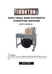
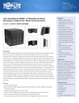
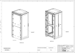
Integrated Cabinet Solutions
For Business-Critical Continuity™
DCF™ Optimized Rack System
User Manual
IMPORTANT SAFETY GUIDELINES
SAVE THESE INSTRUCTIONS
This manual contains important instructions that should be closely followed during installation and
maintenance of this unit. Read all safety instructions before attempting to assemble and install the
DCF Optimized Rack System. Adhere to all warnings on the unit and in this manual. Follow all
instructions.
Read all warnings, cautions and instructions in this before attempting to move, lift, remove packaging
from or preparing unit for installation.
This product is designed for commercial / industrial use only. This product is not intended for use
with life support or other U.S. FDA designated “critical” devices. Maximum load rating for DCF Optimized Rack System can be found in the DCF Guide Spec SL-11392. User must not exceed the static
load rating.
Operate this product in a clean, indoor environment that is free of moisture, flammable liquids, gases
and corrosive substances.
Ensure that the DCF Optimized Rack System has proper ventilation. Never block or insert objects
into the ventilation holes or other openings. Maintain a minimum clearance of 12 inches (305mm) in
front, rear and top of the DCF Optimized Rack System for proper air flow and cooling.
TABLE OF CONTENTS
IMPORTANT SAFETY GUIDELINES . . . . . . . . . . . . . . . . . . . . . . . . . . . . . . . . . . . . . . . . . . . . . . . . . .2
1.0
INTRODUCTION . . . . . . . . . . . . . . . . . . . . . . . . . . . . . . . . . . . . . . . . . . . . . . . . . . . . . . . . . .1
2.0
MAJOR COMPONENTS . . . . . . . . . . . . . . . . . . . . . . . . . . . . . . . . . . . . . . . . . . . . . . . . . . . .2
2.1
Frame . . . . . . . . . . . . . . . . . . . . . . . . . . . . . . . . . . . . . . . . . . . . . . . . . . . . . . . . . . . . . . . . . . . . . 2
2.1.1
2.1.2
2.1.3
2.2
Adjustable Rails . . . . . . . . . . . . . . . . . . . . . . . . . . . . . . . . . . . . . . . . . . . . . . . . . . . . . . . . . . . . . . 2
Full Height Rack PDU/Cable Management Bracket . . . . . . . . . . . . . . . . . . . . . . . . . . . . . . . . . 2
Casters . . . . . . . . . . . . . . . . . . . . . . . . . . . . . . . . . . . . . . . . . . . . . . . . . . . . . . . . . . . . . . . . . . . . . 2
Enclosure . . . . . . . . . . . . . . . . . . . . . . . . . . . . . . . . . . . . . . . . . . . . . . . . . . . . . . . . . . . . . . . . . . 2
2.2.1
2.2.2
2.2.3
Doors . . . . . . . . . . . . . . . . . . . . . . . . . . . . . . . . . . . . . . . . . . . . . . . . . . . . . . . . . . . . . . . . . . . . . . . 2
Side Panels . . . . . . . . . . . . . . . . . . . . . . . . . . . . . . . . . . . . . . . . . . . . . . . . . . . . . . . . . . . . . . . . . . 3
Top Cover . . . . . . . . . . . . . . . . . . . . . . . . . . . . . . . . . . . . . . . . . . . . . . . . . . . . . . . . . . . . . . . . . . . 4
2.3
Mounting Hardware & Tools . . . . . . . . . . . . . . . . . . . . . . . . . . . . . . . . . . . . . . . . . . . . . . . . . . . 4
3.0
INSTALLATION . . . . . . . . . . . . . . . . . . . . . . . . . . . . . . . . . . . . . . . . . . . . . . . . . . . . . . . . . .5
3.1
Inspection . . . . . . . . . . . . . . . . . . . . . . . . . . . . . . . . . . . . . . . . . . . . . . . . . . . . . . . . . . . . . . . . . . 5
3.2
Required Setup equipment . . . . . . . . . . . . . . . . . . . . . . . . . . . . . . . . . . . . . . . . . . . . . . . . . . . . 5
3.3
Unloading the DCF Optimized Rack System . . . . . . . . . . . . . . . . . . . . . . . . . . . . . . . . . . . . . . 6
3.4
Equipment Layout, Repositioning, Removal and Installation. . . . . . . . . . . . . . . . . . . . . . . . . 6
3.4.1
3.4.2
3.4.3
3.4.4
Installing the Edge Guard . . . . . . . . . . . . . . . . . . . . . . . . . . . . . . . . . . . . . . . . . . . . . . . . . . . . . . 7
Front- and Rear-Mount 19" EIA Rails—Position and Attach . . . . . . . . . . . . . . . . . . . . . . . . . . 7
Door—Remove and Reverse . . . . . . . . . . . . . . . . . . . . . . . . . . . . . . . . . . . . . . . . . . . . . . . . . . . . . 9
Side Panels . . . . . . . . . . . . . . . . . . . . . . . . . . . . . . . . . . . . . . . . . . . . . . . . . . . . . . . . . . . . . . . . . 10
3.5
Power Distribution Unit Mounting . . . . . . . . . . . . . . . . . . . . . . . . . . . . . . . . . . . . . . . . . . . . . 11
3.6
Full-Height PDU/Cable Management Brackets . . . . . . . . . . . . . . . . . . . . . . . . . . . . . . . . . . . 11
3.6.1
3.6.2
3.6.3
Install a Full-Height PDU/Cable Management Bracket . . . . . . . . . . . . . . . . . . . . . . . . . . . . . 11
Reposition a Full-Height PDU/Cable Management Bracket . . . . . . . . . . . . . . . . . . . . . . . . . . 11
Remove a Full-Height PDU/Cable Management Bracket . . . . . . . . . . . . . . . . . . . . . . . . . . . . 11
3.7
Baying Configuration . . . . . . . . . . . . . . . . . . . . . . . . . . . . . . . . . . . . . . . . . . . . . . . . . . . . . . . . 12
4.0
PERIODIC MAINTENANCE . . . . . . . . . . . . . . . . . . . . . . . . . . . . . . . . . . . . . . . . . . . . . . . . . 13
5.0
SPECIFICATIONS . . . . . . . . . . . . . . . . . . . . . . . . . . . . . . . . . . . . . . . . . . . . . . . . . . . . . . . .14
i
FIGURES
Figure 1
Figure 2
Figure 3
Figure 4
Figure 5
Figure 6
Figure 7
Figure 8
Figure 9
Figure 10
Figure 11
Figure 12
Figure 13
Caster plate . . . . . . . . . . . . . . . . . . . . . . . . . . . . . . . . . . . . . . . . . . . . . . . . . . . . . . . . . . . . . . . . . . . . . 2
Top cover for DCF Optimized Rack System 1100mm and 1200mm deep . . . . . . . . . . . . . . . . . . . . 4
DCF Optimized Rack System as shipped . . . . . . . . . . . . . . . . . . . . . . . . . . . . . . . . . . . . . . . . . . . . . 5
Removing rack from shipping pallet . . . . . . . . . . . . . . . . . . . . . . . . . . . . . . . . . . . . . . . . . . . . . . . . . 6
Applying the edge guard. . . . . . . . . . . . . . . . . . . . . . . . . . . . . . . . . . . . . . . . . . . . . . . . . . . . . . . . . . . 7
19" EIA rail repositioning . . . . . . . . . . . . . . . . . . . . . . . . . . . . . . . . . . . . . . . . . . . . . . . . . . . . . . . . . . 8
19" EIA rail repositioning—800mm cabinets . . . . . . . . . . . . . . . . . . . . . . . . . . . . . . . . . . . . . . . . . . 8
Door hinge removal . . . . . . . . . . . . . . . . . . . . . . . . . . . . . . . . . . . . . . . . . . . . . . . . . . . . . . . . . . . . . . . 9
Alternate door hinge position and grounding wire location . . . . . . . . . . . . . . . . . . . . . . . . . . . . . . 10
Side panel installation . . . . . . . . . . . . . . . . . . . . . . . . . . . . . . . . . . . . . . . . . . . . . . . . . . . . . . . . . . . 10
Full-height PDU/cable management brackets . . . . . . . . . . . . . . . . . . . . . . . . . . . . . . . . . . . . . . . . 11
Baying brackets. . . . . . . . . . . . . . . . . . . . . . . . . . . . . . . . . . . . . . . . . . . . . . . . . . . . . . . . . . . . . . . . . 12
DCF Optimized Rack System model numbers . . . . . . . . . . . . . . . . . . . . . . . . . . . . . . . . . . . . . . . . 14
TABLES
Table 1
Table 2
Table 3
Table 4
Table 5
Rack dimensions . . . . . . . . . . . . . . . . . . . . . . . . . . . . . . . . . . . . . . . . . . . . . . . . . . . . . . . . . . . . . . . . . 1
Door dimensions, split doors . . . . . . . . . . . . . . . . . . . . . . . . . . . . . . . . . . . . . . . . . . . . . . . . . . . . . . . 3
Side panel sizes and part numbers . . . . . . . . . . . . . . . . . . . . . . . . . . . . . . . . . . . . . . . . . . . . . . . . . . 3
Door dimensions, single door . . . . . . . . . . . . . . . . . . . . . . . . . . . . . . . . . . . . . . . . . . . . . . . . . . . . . . . 3
DCF pre-configured optimized rack systems. . . . . . . . . . . . . . . . . . . . . . . . . . . . . . . . . . . . . . . . . . 14
ii
Introduction
1.0
INTRODUCTION
The highly versatile DCF Optimized Rack System provides an organized, secure, controlled
environment in a single system for sensitive electronic equipment.
The DCF Optimized Rack System is available in two heights—42U and 48U (78.1" and 88.6";
1985mm and 2251mm). Those cabinet heights are available in these widths and depths:
Table 1
Rack dimensions
Dimensions, in (mm)
Height
Width
Depth
Frame Only
With
Leveling Feet
With
Casters
With and
Without
Side Panels
Without
Doors
With
Doors
42U
76.2 (1936.6)
77 (1956.2)
78.1 (1984.7)
23.6 (600)
41.8 (1062.5)
43.3 (1100)
48U
86.7 (2203.3)
87.5 (2222.9)
88.6 (2251.4)
31.5 (800)
45.8 (1162.5)
47.2 (1200)
Rack
Size
Height, width, and depth dimensions are independent.
Depth with door is measured from the front door frame to the rear door frame.
Assembly instructions in this manual cover the various configurations of the DCF Optimized Rack
System, either a single rack for simple equipment organization or a suite of DCF Optimized Rack
System racks.
1
Major Components
2.0
MAJOR COMPONENTS
DCF Optimized Rack System will have all of the components addressed in this section. All
components are finished with a textured powder coat, color is RAL 7021.
2.1
Frame
The DCF Optimized Rack System is constructed of hot and cold rolled steel. Frame is light weight and
strong with a 3000lb static load rating.
2.1.1
Adjustable Rails
The DCF Optimized Rack System ships with 2 sets of 19" (EIA310-E) compliant rails. The 19" rails
have U marking labels on both sides of the rails. Front and rear mount rails are installed in the DCF
at 29.13" (740mm).
2.1.2
Full Height Rack PDU/Cable Management Bracket
Each DCF rack leaves the factory with two full height rack pdu/cable management brackets installed.
The brackets are installed in the rear of the rack, flush against the frame, one bracket installed on
each side of rack.
2.1.3
Casters
DCF Optimized Rack System ships standard with 4 swivel, non-locking casters installed.
Figure 1
2.2
Caster plate
Enclosure
Exterior components of the DCF Optimized Rack System are finished in textured powder coat, color
RAL 7021.
2.2.1
Doors
All doors for the DCF are framed from sheet metal and have hexagonal perforations leaving 75% open
for airflow and efficient cooling. All doors have a single point latch system and come standard with
lock. The DCF rack ships with a single contoured perforated front door and split perforated rear doors
designed for easy access. All doors can easily be removed and the single contoured front door is
designed for reversibility (left/right) hinging in the field. (See 3.4.2 for door removal and reverse.)
Each door opens to 135 degrees.
2
Major Components
Table 2
Door dimensions, single door
Door Dimensions, in (mm)
Frame Size
42U
48U
Table 3
Height
78.1 x 23.6 (2000 x 600)
78.1 x 31.5 (2000 x 800)
83.4 x 23.6 (2100 x 600)
83.4 x 31.5 (2100 x 800)
76 (1931.5)
87 (2198.2)
Width
Part Number
23 (586)
Part # 546053G1L
31 (768)
Part # 546053G2L
23 (586)
Part # 546053G3L
31 (768)
Part # 546053G4L
Door dimensions, split doors
Door Dimensions, in (mm)
Frame Size
42U
48U
2.2.2
Height
78.1 x 23.6 (2000 x 600)
78.1 x 31.5 (2000 x 800)
83.4 x 23.6 (2100 x 600)
83.4 x 31.5 (2100 x 800)
76 (1931.5)
87 (2198.2)
Width
Each Door
Part Number
11.5 (293)
Part # 546054G1L
15.5 (384)
Part # 546054G2L
11.5 (293)
Part # 546054G3L
15.5 (384)
Part # 546054G4L
Side Panels
Side panels for the DCF Optimized Rack System are a split side panel design constructed of sheet
metal. Each side panel section comes with a lock for security which is installed in the center top of
each panel. Two keys ship with the side panels; the side panel keys are the same keys that are used
for the doors.
Table 4
Side panel sizes and part numbers
Rack Height, in
(mm)
78.1 (2000)
88.6 (2250)
Rack Depth, in
(mm)
Side Panel
Part Numbers
43.3 (1100)
546055G1L
47.2 (1200)
546055G2L
43.3 (1100)
546055G3L
47.3 (1200)
546055G4L
3
Major Components
2.2.3
Top Cover
All DCF racks ship with top cover constructed of sheet metal. The top cover has cutouts for fan
mounting, cabling, and cagenut installation which allows mounting of certain DCF accessories.
Figure 2
2.3
Top cover for DCF Optimized Rack System 1100mm and 1200mm deep
Mounting Hardware & Tools
Hardware to install additional accessories ships with the DCF rack. A bag of 50 M6 cagenuts, 50
M6x12 pan head screws, 50 nylon washers, 1 cagenut insertion tool, 1 #13/14 wrench, 1 L Key with a
T30 torx head and Phillips head, 9FT of black edge guard, and 1 baying kit.
4
Installation
3.0
INSTALLATION
3.1
Inspection
Upon receiving a DCF Optimized Rack System, examine the packaging for any signs of mishandling
or damage. If any damage is noted, notify your local Emerson® representative and your carrier
immediately.
Figure 3
DCF Optimized Rack System as shipped
Tilt Indicator shows whether
the unit was been tilted beyond
the allowable limit or
mishandled during shipping
Shrink wrap secures corrugated
corner protectors to the DCF
cabinet and shields the unit
from contact damage
Part Number and
Serial Number
Corrugated Corner
Protectors at each
corner
Anchor Brackets secure DCF
to shipping pallet; one bracket
in front and one in rear of rack
(packaging removed)
Bolts shown below.
3.2
Required Setup equipment
Each DCF Optimized Rack System ships with all the tools necessary to adjust supplied components.
The tool kit contains the following tools:
• cagenut tool
• 13/14mm wrench
• combination T30 Torx L-key with Phillips head
The following tools are required to set up a DCF Optimized Rack System:
• pallet jack or forklift
• utility knife or scissors
• 14mm socket and rachet or 14mm wrench
5
Installation
3.3
Unloading the DCF Optimized Rack System
Before unloading a DCF Optimized Rack System, note the weight of the model (see 5.0 Specifications. Use at least two people when moving the unit.
1. Using a pallet jack or forklift, move the DCF Optimized Rack System on its pallet to the
installation location.
2. Cut the shrink wrap and remove all packaging.
3. Use a 14mm socket or a 14mm wrench to remove the lag bolts securing each shipping bracket to
the shipping pallet. There are two brackets, one in the front and one at the rear of the rack. Each
bracket is secured by four bolts (see Figure 4).
Shipping bracket can also be used as an anchor bracket once unit is at final resting place. Leave
the shipping brackets attached if they will be used to secure the rack to the floor.
4. Use a pallet jack or forklift to raise the DCF Optimized Rack System off the shipping pallet.
5. Slide the shipping pallet out from under the rack.
The DCF Optimized Rack System may be positioned for installation either with the forklift, by two or
more people carrying it or by rolling the rack on its casters.
If the casters are to be used to move the rack, the leveling feet must be raised. Position the rack and
either lower the leveling feet or bolt the rack to the floor with the shipping/anchoring brackets.
Figure 4
Removing rack from shipping pallet
Shipping/Anchor Bracket
DCF rack will rest on casters when
removing the shipping/bolt-down bracket.
Leave brackets
bolted to the rack
if they will be used
to secure the rack
to the floor.
Remove lag bolts from brackets
on front and rear of the rack...
3.4
... to free the shipping bracket
from the pallet.
Equipment Layout, Repositioning, Removal and Installation
To keep the unit’s center of gravity as low as possible, install equipment from the bottom up, starting
with the heavier units. Leave any unused space at the top of the rack.
! CAUTION
After equipment is installed, the DCF Optimized Rack System may have a high center of
gravity. Avoid tipping the unit when it is being moved.
6
Installation
3.4.1
Installing the Edge Guard
1. Press edge guard to top cover cut outs by pressing along the edge of the cut out opening.
2. Trim excess edge guard with a pair of scissors after the edge guard has been completely applied
around the opening.
3. Repeat Steps 1 and 2 for remaining cut outs.
Figure 5
3.4.2
Applying the edge guard
Front- and Rear-Mount 19" EIA Rails—Position and Attach
Front- and rear-mount 19" EIA rails are installed in DCF racks at the factory at 29.13 inches
(740mm). They are attached to the cabinet frame at top and bottom, attach in center to the DCF
support member using M6x12 torx head screw into a rail adjustment bracket. 19" EIA rails in 800mm
wide racks are attached using node brackets. The node brackets attach to the top and bottom of the
DCF frame and in the center to the DCF support member. The 19" EIA rails are attached to the node
brackets and move as a unit if they need to be repositioned.
NOTE
The front and rear 19" EIA rails must be kept at a 90-degree angle to the upper and lower
frame members. The left and right front vertical rails must be the same distance from the front
of the rack; the left and right rear vertical rails must be the same distance from the rear of the
rack.
If those conditions are not met, equipment and optional features will be difficult to install.
Position 19" EIA Rails
1. Determine the desired location of the 19" EIA rails.
2. Loosen the M6x12 screws in the rail adjustment brackets securing the 19" EIA rails to the frame
member (see Figure 6).
Rails in both the 600 and 800mm wide racks are attached at the top, center and bottom.
3. Slide the rail adjustment brackets either up or down, depending on their orientation in the rack.
4. Slide the 19" EIA rail to the desired position, making sure it is kept square as described in the
Note above. The frame member and support have small holes spaced on 6.35mm centers to assist
in properly positioning the 19" EIA rails.
5. Hold the rail in position, then tighten the M6x12 screws into the rail adjustment brackets.
6. Repeat Steps 2 through 5 for the corresponding 19" EIA rail.
7
Installation
Figure 6
19" EIA rail repositioning
19" EIA
rail face
Frame
member
where 19"
EIA rail is
attached
Holes in frame member
are 6.35mm apart
Loosen this screw
to let rail slide
Position 19" EIA Rails on 800mm Cabinets
1. Determine the proper location of the 19" EIA rails.
2. Loosen the two screws that secure the node adjustment brackets to the bottom frame member,
then slide the bracket down.
Repeat on the other two node adjustment brackets attached to the frame and center support
member.
3. Slide the 19" EIA rails to their new location. The rails will bind if they are not kept at a right
angle to the frame.
4. Tighten all hardware.
Figure 7
19" EIA rail repositioning—800mm cabinets
Node Adjustment Bracket
Hangs on frame member and
depth support member
EIA Rails
attach
here
8
Node bracket attached at the
center depth support
Installation
3.4.3
Door—Remove and Reverse
DCF doors are removable for convenience when installing or maintaining equipment. The DCF front
door is also reversible, so the single-door may be opened in a more convenient direction if the rack is
near a wall or other equipment.
Doors are supported by two hinges and held in place by gravity. They can be lifted off and reinstalled
without tools (see Figure 8).
NOTE
Doors are easier to remove if they are open at a 90° angle to the DCF cabinet.
Figure 8
Door hinge removal
Door
Frame
Torx head screws
hold the hinge pin
assembly to the
DCF frame
Door Hinge
Torx Head screws
fit here when the
door is flipped to
change the swing
direction
Reverse the Door
NOTE
The door handle cannot be reversed.
1.
2.
3.
4.
5.
6.
Lift the door off the DCF.
Loosen and remove screws from both the top and bottom hinges.
Remove the hinges and place them on the opposite side of the frame in the slots provided.
Reinsert and tighten the screws.
Remove the hardware from the door catch and install the catch on the opposite side of the frame.
Flip the door.
The hinge pin assemblies will now be at bottom of the hinge pin attachment point.
7. Remove the hardware, flip the hinge pin and reinsert it in the hinge pin attachment point.
8. Reattach the hinge pin with hardware.
9. Hang the door on the newly positioned hinges.
9
Installation
Figure 9
Alternate door hinge position and grounding wire location
Ground Wire Bolt Hole and Symbol
Hinge Location when
Reversing Door
3.4.4
Side Panels
The DCF uses dual split side panels fashioned from sheet metal. The lower panel hangs on a frame
member and the upper panel hangs on the rack frame. Each panel is secured with a lock. The
arrangement makes the panels simple to remove and replace, making it easier to install equipment.
Panel removal also eases maintenance and replacing equipment.
Figure 10 Side panel installation
Side Panel Lock
Inside
Side Panel Lock
Outside
Remove a Panel
To remove a panel, insert the key in the side panel lock and turn it clockwise to unlock it. Lift the
panel up and away from the rack. Set it aside. Repeat for other panels being removed.
Replace a Side Panel
To install the Side Panel:
1.
2.
3.
4.
Insert the bottom panel into cutouts.
Move the top of the panel toward the rack.
Turn the key counterclockwise to lock the panel in place.
Repeat Steps 1 through 3 for other panels being replaced.
10
Installation
3.5
Power Distribution Unit Mounting
Power distribution units may be mounted multiple ways in the DCF Optimized Rack System rack.
They may be mounted on the rails or attached to mounting brackets:
• 42U full height PDU/cable management mounting brackets (4"W) (Part # 546076G1L)
• 48U full height PDU/cable management mounting brackets (4"W) (Part # 546077G1L)
3.6
Full-Height PDU/Cable Management Brackets
3.6.1
Install a Full-Height PDU/Cable Management Bracket
1. Position the full-height PDU mounting bracket for installation; refer to Figure 11 for placement.
The inside bottom flange of the PDU hanging bracket should rest on the flange of the frame
member at the top and bottom.
2. Hold the PDU bracket in place and insert and tighten the screws.
3.6.2
Reposition a Full-Height PDU/Cable Management Bracket
1. Loosen the screws in the top and bottom PDU hanging bracket.
2. Slide the full height pdu/cable management bracket along the frame member to the desired
location and tighten the screws.
3.6.3
Remove a Full-Height PDU/Cable Management Bracket
1. Loosen the screws in the top and bottom PDU hanging bracket.
2. Lift the bracket up so the hanging bracket clears the frame member and remove the full-height
PDU/cable management bracket from the DCF.
Figure 11 Full-height PDU/cable management brackets
Full-height PDU/cable
management bracket
flange grips DCF frame
Top and bottom ends of full-height PDU/
cable management brackets are identical,
permitting use on either side of the
cabinet; 4" wide
PDU hanging bracket
clips on top of frame
member flange
11
Installation
3.7
Baying Configuration
Two or more DCF cabinets of the same height can be bayed with the supplied baying brackets. The
brackets have three holes: one that connects to the DCF, one that puts the cabinets on 24" (609.6mm)
centers and one that puts the cabinets on metric centers.
Connecting DCF racks is easier if the units have been moved to their final installation position before
beginning to attach them in a cluster.
Figure 12 Baying brackets
Screws and
baying brackets
to connect DCF
cabinets
Using outer holes puts
cabinets on 24" centers.
Using the center hole
and the hole at the far
left puts the racks on
metric centers.
12
Periodic Maintenance
4.0
PERIODIC MAINTENANCE
Your DCF Optimized Rack System cabinet requires no special maintenance. It should be cleaned
periodically, more frequently if the air in the vicinity is not filtered for particulates.
Dust should be cleaned from installed equipment according to the manufacturer’s recommendations.
Clean the interior of the cabinet with a dry cloth.
13
Specifications
5.0
SPECIFICATIONS
Figure 13 DCF Optimized Rack System model numbers
F
2
6
1
PRODUCT
F = DCF
Optimized Rack
System
1
1
2
2
1
FRONT DOOR
1 = Single, Perforated
Door
HEIGHT
2 = 42U (2000mm)
8 = 48U (2250mm)
WIDTH
6 = 600mm (23.6")
8 = 800mm (31.5")
REAR DOOR
2 = Split,
Perforated
Door
SIDE PANELS
2 = 2 Side Panels
FACTORY-INSTALLED OPTIONS
1 = Factory-Installed Options
Placeholder
1
DEPTH
1 = 1100mm (43.3")
2 = 1200mm (47.2")
INTEGRATED PDU’s
0 = None
1 = One PDU
2 = Two PDU’s
F261112211
The sample part number above and at the top of
the page specifies a DCF Optimized Rack
System with these characteristics:
• Height—2000mm (42U)
• Width—600mm (23.6")
• Depth—1100mm (43.3")
• Front Door—single, perforated
• Rear Door—split, perforated door
• Side Panels—2
• Factory-Installed Options
• Integrated PDU’s—1
Table 5
DCF pre-configured optimized rack systems
Part #
Description
F2611
42U X 24" W X 44"D With Sides
F2612
42U X 24" W X 48" D With Sides
F2811
42U X 32" W X 44" D With Sides
F2812
42U X 32" W X 48" D With Sides
F8611
48U X 24" W X 44" D With Sides
F8612
48U X 24' W X 48" D With Sides
F8811
48U X 32" W X 44" D With Sides
F8812
48U X 32" W X 48" D With Sides
14
1
Ensuring The High Availability
Of Mission-Critical Data And Applications.
Emerson Network Power, a business of Emerson (NYSE:EMR),
is the global leader in enabling Business-Critical Continuity™
from grid to chip for telecommunication networks, data centers,
health care and industrial facilities. Emerson Network Power
provides innovative solutions and expertise in areas including
AC and DC power and precision cooling systems, embedded
computing and power, integrated racks and enclosures,
power switching and controls, infrastructure management,
and connectivity. All solutions are supported globally by local
Emerson Network Power service technicians. Liebert AC power,
precision cooling and monitoring products and services
from Emerson Network Power deliver Efficiency Without
Compromise™ by helping customers optimize their data center
infrastructure to reduce costs and deliver high availability.
Technical Support / Service
Web Site
www.liebert.com
Monitoring
[email protected]
800-222-5877
Outside North America: +00800 1155 4499
Single-Phase UPS & Server Cabinets
[email protected]
800-222-5877
Outside North America: +00800 1155 4499
Three-Phase UPS & Power Systems
800-543-2378
Outside North America: 614-841-6598
Environmental Systems
800-543-2778
Outside the United States: 614-888-0246
Locations
United States
1050 Dearborn Drive
P.O. Box 29186
Columbus, OH 43229
Europe
Via Leonardo Da Vinci 8
Zona Industriale Tognana
35028 Piove Di Sacco (PD) Italy
+39 049 9719 111
Fax: +39 049 5841 257
Asia
29/F, The Orient Square Building
F. Ortigas Jr. Road, Ortigas Center
Pasig City 1605
Philippines
+63 2 687 6615
Fax: +63 2 730 9572
While every precaution has been taken to ensure the accuracy
and completeness of this literature, Liebert Corporation assumes no
responsibility and disclaims all liability for damages resulting from use of
this information or for any errors or omissions.
© 2012 Liebert Corporation
All rights reserved throughout the world. Specifications subject to change
without notice.
® Liebert is a registered trademark of Liebert Corporation.
All names referred to are trademarks
or registered trademarks of their respective owners.
SL-11391_REV0_05-12
Emerson Network Power.
The global leader in enabling Business-Critical Continuity™
AC Power
Connectivity
Embedded Computing
Embedded Power
DC Power
Infrastructure Management & Monitoring
Outside Plant
Power Switching & Controls
Precision Cooling
EmersonNetworkPower.com
Racks & Integrated Cabinets
Services
Surge Protection
Emerson, Business-Critical Continuity, Emerson Network Power and the Emerson Network Power logo are trademarks of Emerson Electric Co. or one of its affiliated companies.
©2012 Emerson Electric Co.