1
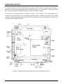
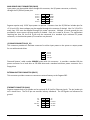
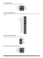
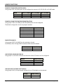
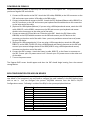
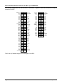
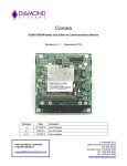
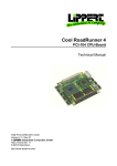
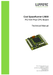
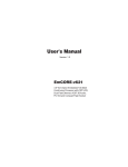
Pegasus Fast Start Guide DSC Document #7460572 Rev A Pegasus is a rugged, low‐power PC/104‐Plus Single Board Computer (SBC) with a 500MHz AMD LX800 CPU, 256MB of on‐board DRAM and an optional 2GB on‐board IDE flashdisk. This Fast Start Guide provides an overview of Pegasus’ features, a listing of products, information on the I/O connections and jumpers on‐board, BIOS and IDE considerations, and a basic procedure for powering up the SBC. For more detailed information please refer to the Pegasus User Manual. PEGASUS KEY FEATURES ♦
♦
♦
♦
♦
Low power, mid‐range PC/104‐Plus expandable single board computer AMD Geode LX800 processor operating fan‐less at 500MHz 256MB DDR DRAM soldered on‐board 2GB on‐board IDE flashdisk (model PGS800‐256‐2G only) Fully featured including support for: o
o
o
o
o
o
o
o
♦
♦
♦
Four USB 2.0 ports One RS‐232 serial port One RS‐232/422/485 serial port 10/100Mbps Ethernet IDE hard drive interface for one device Type II CompactFlash socket VGA CRT and 1280 X 1024 LCD PS/2 Keyboard and Mouse Support for Windows XP, Windows XPe, Windows CE, Linux, and DOS PC/104‐Plus (ISA + PCI) stackthrough expansion ‐40°C to +85°C operating temperature PRODUCT MODEL NUMBERS Model Description PGS800‐256‐2G Pegasus SBC, 500MHz LX800, 256MB on‐board DRAM, 2GB on‐board IDE flashdisk PGS800‐256 Pegasus SBC, 500MHz LX800, 256MB on‐board DRAM, no on‐board IDE flashdisk C‐PGS‐KIT Pegasus Cable Kit CONNECTOR FUNCTIONS The board conforms to PC/104 specifications for the four corners and four mounting holes. Wings, or extensions on the left and right sides, provide additional room for I/O connectors. The wings extend 0.25” past the standard PC/104 board edges as shown in the Figure 1 below. The connector and jumper layout is provided in Figures 1 and 2 below. This layout enables most connectors to be positioned in the board wings and also provides sufficient clearance for the mating connectors when latching connectors are used. All I/O connectors are vertical except for the power I/O, external battery and optional RJ‐45. Figure 1. Pegasus top drawing showing connector and jumper locations Pegasus Fast Start Guide
7460572 Rev A
Page 2 of 12
Figure 2. Pegasus bottom drawing showing connector and jumper locations The following pages describe the pin outs for the Pegasus connectors. Unless otherwise indicated, pins marked as Key are cut away or removed from the connector. Pegasus Fast Start Guide
7460572 Rev A
Page 3 of 12
MAIN POWER INPUT CONNECTOR (PWR1) Input power may be supplied either through this connector, the I/O power connector, or directly through the PC/104 bus power pins. Ground Ground Ground Key Ground 1 3 5 7 9 2 4 6 8 10 +5VDC +12VDC ‐12VDC +5VDC +5VDC Pegasus requires only +5VDC input power to operate. However since the PC/104 bus includes pins for +3.3V and ±12V, these voltages may be supplied through this connector if desired. Also if a 3.3V LCD is used, then 3.3V must be supplied through this power connector. Multiple +5V and ground pins are provided for extra current carrying capacity if needed. Each pin is rated at 3A max. For applications requiring less than 3A, the first 4 pins may be connected to a standard 4‐pin miniature PC power connector, or the alternate power I/O connector may be used. I/O POWER CONNECTOR (IO_P1) This connector provides an alternate connector for either input power to the system or output power for use with external drives. 1
2
3
4
+5V I/O Ground Ground +12V I/O Diamond Systems’ cable number 6981006 mates with this connector. It provides a standard full‐size power connector for a hard drive or CD‐ROM drive and a standard miniature power connector for a floppy drive. EXTERNAL BATTERY CONNECTOR (EBAT1) This connector provides a means to connect an external battery to the Pegasus SBC. 1
2
Ground +3.3VDC ETHERNET CONNECTOR (LAN1) Pegasus supports both a pin header and an optional RJ‐45 jack for Ethernet signals. The pin header pin out is shown here. The RJ‐45 pin out matches industry standards. The LED signals are referenced to ground. TX+ NC RX+ Link LED+ Key 1 3 5 7 9 2 4 6 8 10 TX‐ RX‐ Link LED‐ Act LED+ Act LED‐ Pegasus Fast Start Guide
7460572 Rev A
Page 4 of 12
SERIAL PORT CONNECTOR (COM1) This connector provides access to the 2 serial ports from the CPU chip. Port 1 is RS‐232 only and Port 2 may be jumper‐configured for RS‐232, RS‐422 or RS‐485 protocols. In RS‐422/485 mode, the port may have a jumper‐selectable 120‐ohm termination resistor across the RX pins and jumper‐selectable pull‐
up/pull‐down resistors on the TX/RX lines. The RX resistors are configured so that the port reads back a 0 when it is open circuit. RS‐232 Configuration Port 1 DCD 1 RXD 1 TXD 1 DTR 1 Ground Port 2 DCD 2 RXD 2 TXD 2 DTR 2 Ground 1 3 5 7 9 11 13 15 17 19 2 4 6 8 10 12 14 16 18 20 RS‐422 Configuration DSR 1 RTS 1 CTS 1 RI 1 Ground DSR 2 RTS 2 CTS 2 RI 2 Ground NC TX+ RX+ NC Ground 11 13 15 17 19 12 14 16 18 20 NC TX‐ RX‐ NC Ground RS‐485 configuration NC RTX+ NC NC Ground 11 13 15 17 19 12 14 16 18 20 NC RTX‐ NC NC Ground USB CONNECTORS (USB1 and USB2) These connectors provide access to the four USB 2.0 ports. The shield pin is tied to system ground. The key positions are missing to match the key position in the cable to prevent misconnection. Both connectors have the same pin out. Ground Channel 0 Data+ Key Ground Channel 1 Data+ 1 3 5 7 9 2 4 6 8 10 +5V Channel 0 Data ‐ Ground +5V Channel 1 Data ‐ Ground Channel 2 Data+ Key Ground Channel 3 Data+ 1 3 5 7 9 2 4 6 8 10 +5V Channel 2 Data ‐ Ground +5V Channel 3 Data ‐ Pegasus Fast Start Guide
7460572 Rev A
Page 5 of 12
PS/2 KEYBOARD / MOUSE CONNECTOR (KBMS1) This connector provides the standard PS/2 keyboard and mouse signals. +5V KB Data KB Clock Ground NC 1 3 5 7 9 2 4 6 8 10 +5V MS Data MS Clock Key Ground +5V KB Data, MS Data KB Clock, MS Clock Ground Power; connects to pin 4 of the PS/2 connector. Data; connects to pin 1 of the PS/2 connector. Clock; connects to pin 5 of the PS/2 connector. Ground; connects to pin 3 of the PS/2 connector. Note: Pins 2 and 6 on the Mini‐Din‐6 PS/2 connectors are unused. NC No Connection IDE/FLASHDISK CONNECTOR (IDE1) RESET‐ D7 D6 D5 D4 D3 D2 D1 D0 Ground DRQ IDEIOW‐ IDEIOR‐ IORDY DACK‐ IRQ14 A1 A0 CS0‐ LED‐ +5V Ground 1 3 5 7 9 11 13 15 17 19 21 23 25 27 29 31 33 35 37 39 41 43 2 4 6 8 10 12 14 16 18 20 22 24 26 28 30 32 34 36 38 40 42 44 Ground D8 D9 D10 D11 D12 D13 D14 D15 Key Ground Ground Ground Ground Ground Pulled low for 16‐bit operation Not Used A2 CS1‐ Ground +5V Not Used This connector is a 2x22 (44‐pin) 2mm‐pitch SMT (not through‐hole) pin header with gold flash plating. It mates with Diamond Systems’ cable number 6981004, and may be used to connect an external IDE drive (hard disk or CD‐ROM). Alternately, an IDE flashdisk module can be plugged into the IDE/Flashdisk connector. Note Pin 20 is removed for keying to prevent incorrect cable installation. Pegasus Fast Start Guide
7460572 Rev A
Page 6 of 12
VGA CONNECTOR (VGA1) This connector provides the connection for a VGA display. CRed CGreen CGlue CHSync CVSync 1 3 5 7 9 2 4 6 8 10 Ground Key Ground DDC Data DDC Clock LCD PANEL CONNECTOR (LVDS1) This connector is located on the bottom of the Pegasus SBC and provides the connection for a LVDS LCD display. NC NC Scan Direction Frame Rate Control Ground LVDS Clock+ LVDS Clock‐ Ground LVDS D2+ LVDS S2‐ Ground LVDS D1+ LVDS D1‐ Ground LVDS D0+ LVDS D0‐ Ground Ground VDD SEL VDD SEL 1 2 3 4 5 6 7 8 9 10 11 12 13 14 15 16 17 18 19 20 LCD BACKLIGHT CONNECTOR (INV1) This connector provides connection for the LCD backlight. 1
2
3
4
5
6
INV SEL INV SEL Ground Ground DISPEN Brightness MISCELLANEOUS SIGNALS CONNECTOR (MIS1) Ground ‐HDDLED PLED‐ ‐SPKOUT Brightness Pegasus Fast Start Guide
1 3 5 7 9 2 4 6 8 10 7460572 Rev A
Reset +5V +5v +5V Key Page 7 of 12
JUMPER FUNCTIONS COM2 RS‐232/422/485 SELECTION (JRS1) Using jumper JRS1, the COM2 port can be configured to operate in RS‐232, RS‐422 or RS‐485 mode. Mode Pins 1‐2 Jumper Pins 3‐4 Jumper Pins 5‐6 Jumper RS‐232 (Default) RS‐422 RS‐485 ON
OFF
OFF
OFF
ON
OFF
OFF OFF ON COM2 RS‐422/485 FEATURE CONFIGURATION (JTM1) Using jumper JTM1, the COM2 port RS‐422/485 features can be configured. The default configuration is with no jumpers installed. Feature Jumper Setting RS‐422/485 TX+ Pull‐up
RS‐422/485 TX‐ Pull‐down
RS‐422/485 Terminal 120ohm
RS‐422 Terminal 120ohm
RS‐422 RX+ Pull‐up
RS‐422 RX Pull‐down
Pins 1 & 2
Pins 3 & 4
Pins 5 & 6
Pins 7 & 8
Pins 9 & 10
Pins 11 & 12
CMOS SETUP (JBAT1) Using jumper JBAT1, the CMOS can be retained or cleared. Immediately after clearing CMOS the default BIOS should be loaded. Mode Jumper Setting Keep CMOS (Default)
Clear CMOS
Pins 1 & 2
Pins 2 & 3
LCD FEATURE CONFIGURATION (J1) Using jumper J1, the frame rate and scan direction of the LCD device can be configured. Feature Jumper Setting Frame Rate Low (Default)
Frame Rate High
Scan Direction Low (Default)
Scan Direction High
Pins 1 & 3 on
Pins 1 & 3 off
Pins 2 & 4 on
Pins 2 & 4 off
LCD BACKLIGHT VOLTAGE SELECT (JINV1) Using jumper JINV1, the input power voltage for the LCD backlight can be selected. Voltage Jumper Setting +5V (Default)
+12V Pins 1 & 2
Pins 2 & 3
Pegasus Fast Start Guide
7460572 Rev A
Page 8 of 12
LVDS PANEL VOLTAGE SELECT (JVLCD1) Using jumper JVLCD1, the input power voltage for the LVDS panel can be selected. Voltage Jumper Setting +5V
+12V (Default)
Pins 1 & 2
Pins 2 & 3
CABLE NUMBERS Pegasus SBC Cable Kit (C‐PGS‐KIT) Photo Number Item Number Description 1 6981175 Cable, Crimp 2x5 0.1" Power In 2 6981162 Cable, PS/2 Keyboard/Mouse 2mm 2x5 to 2x Mini‐DIN‐6 3 6981006 Cable, Power Out 4 6981171 Cable, Crimp 2x5 2mm, Dual USB (Quantity 2) 5 6981161 Cable, Ethernet RJ45PNL‐CRIMP2x5 2mm,12" 6 6981180 Cable, External Battery 7 6981084 Cable, VGA, DD15F to IDC12 2mm 8 6981081 Cable, Dual Serial Port 2mm 2x10 to 2x DB9M 9 6981004 Cable, 44‐Pos Ribbon IDE Drive 10 6981165 Cable, IDC10FxIDC10F, 2mm, 12" Pegasus Fast Start Guide
7460572 Rev A
Page 9 of 12
POWERING ON PEGASUS Follow these steps to power on and verify the functionality of the Pegasus SBC. This process assumes you have a Pegasus SBC and cable kit. 1. Connect a VGA monitor to the SBC. Attach the VGA cable, 6981084, to the VGA connector on the SBC and connect your monitor VGA cable to the DB9 socket. 2. Connect a keyboard and mouse to the SBC. Attach the PS/2 Keyboard/Mouse cable, 6981162, to the PS/2 connector on the SBC and connect your keyboard and mouse devices to the connectors on the other end of the cable. 3. (Optional for USB Keyboard/Mouse) If you are using a USB keyboard and mouse, attach the USB cable, 6981171, to the USB0‐1 connector on the SBC and connect your keyboard and mouse devices to the connectors on the other end of the cable. 4. Connect an external IDE hard drive or CD device to the SBC. Attach the IDE ribbon cable, 6981004, to the IDE/Flashdisk connector on the SBC and connect your IDE device to the connector on the other end of the cable. Note: you must provide an external source of power for your IDE device. 5. (Optional for USB storage device) If you are using a USB storage device, attach the USB cable, 6981171, to the USB0‐1 (USB2‐3 if using a USB keyboard and mouse) connector on the SBC and connect your external storage device to the USB0 (USB2 if using a USB keyboard and mouse) connector on the other end of the cable. 6. Connect the SBC to power. Attach the Power In cable, 6981175, to the Power In connector on the SBC. Ensure your +5V power source is off. Connect your +5V power source to the other end of the cable. 7. Turn on the power source. The Pegasus BIOS screen should appear and then the SBC should begin booting from the external storage device. BIOS CONFIGURATION FOR ADD‐ON BOARDS When you plug PC/104 boards onto Pegasus, the BIOS may or may not recognize the new board. If the new board is not recognized, you may need to configure the new hardware in the BIOS before being able to use it. You can configure the system’s IRQ/DMA resources from the BIOS’s PnP/PCI Configurations screen. Following is a table of the IRQs for the system peripheral devices. IRQ Level Function IRQ 01 IRQ 03
IRQ 04
IRQ 05
IRQ 05
IRQ 06
IRQ 10
IRQ 10
IRQ 11 IRQ 12 IRQ 14 PC/AT Enhanced PS/2 Keyboard
Communications Port
Communications Port
Standard Enhanced PCI to USB Host Controller
Standard Open HCD USB Host Controller
Standard Floppy Disk Controller
Advanced Micro Devices Win 2K/Win Graphics Driver Geode LX AES Crypto Driver
Realtek RTL8139/810x Family Fast Ethernet NIC
Microsoft PS/2 Mouse
Primary IDE Channel
Pegasus Fast Start Guide
7460572 Rev A
Page 10 of 12
BIOS CONFIGURATION FOR THE ISA BUS I/O ADDRESSES The default configuration for the ISA bus is as follows. Together these two connectors comprise connector PC104PI. IOCHCHK‐ SD7 SD6 SD5 SD4 SD3 SD2 SD1 SD0 IOCHRDY AEN SA19 SA18 SA17 SA16 SA15 SA14 SA13 SA12 SA11 SA10 SA9 SA8 SA7 SA6 SA5 SA4 SA3 SA2 SA1 SA0 Ground A1 A2 A3 A4 A5 A6 A7 A8 A9 A10 A11 A12 A13 A14 A15 A16 A17 A18 A19 A20 A21 A22 A23 A24 A25 A26 A27 A28 A29 A30 A31 A32 B1 B2 B3 B4 B5 B6 B7 B8 B9 B10 B11 B12 B13 B14 B15 B16 B17 B18 B19 B20 B21 B22 B23 B24 B25 B26 B27 B28 B29 B30 B31 B32 Ground RESETDRV
+5V IRQ9 ‐5V DRQ2 ‐12V ENDXFR‐ +12V Key SMEMW‐ SMEMR‐ IOW‐ IOR‐ DACK3‐ DRQ3 DACK1‐ DRQ1 REFRESH‐ SYSCLK IRQ7 IRQ6 IRQ5 IRQ4 IRQ3 DACK2‐ TC BALE +5V OSC Ground Ground Ground SBHE‐ LA23 LA22 LA21 LA20 LA19 LA18 LA17 MEMR‐ MEMW‐ SD8 SD9 SD10 SD11 SD12 SD13 SD14 SD15 Key C0 C1 C2 C3 C4 C5 C6 C7 C8 C9 C10 C11 C12 C13 C14 C15 C16 C17 C18 C19 D0 D1 D2 D3 D4 D5 D6 D7 D8 D9 D10 D11 D12 D13 D14 D15 D16 D17 D18 D19 Ground MEMCS16‐ IOCS16‐ IRQ10 IRQ11 IRQ12 IRQ13 IRQ14 DACK0‐ DRQ0 DACK5‐ DRQ5 DACK6‐ DRQ6 DACK7‐ DRQ7 +5V MASTER‐ Ground Ground The ISA bus I/O address ranges can be changed in the BIOS.
Pegasus Fast Start Guide
7460572 Rev A
Page 11 of 12
CONFIGURING IDE DEVICES The on‐board PCI IDE connector supports two IDE devices: a primary master and a primary slave. The supported IDE devices include the on‐board flashdisk, a CompactFlash disk, a flashdisk plug in module on the IDE connector, or external IDE devices. You can configure the system’s IDE devices from the BIOS’s Standard CMOS Features screen. Many devices have on‐board jumpers for configuring itself as a master or slave. Consult the device’s User Manual for details. The possible IDE device combinations for the two Pegasus models are as follows: Model: PGS800‐256‐2G Master Slave Device on IDE Connector
CompactFlash Disk
2GB on‐board flashdisk
2GB on‐board flashdisk
The 2GB on‐board flashdisk on Pegasus model PGS800‐256‐2G is fixed as the primary slave device and defaults to drive C: if no other bootable device is found. If a bootable device is found as the primary master, the on‐board flashdisk is assigned drive D:. This model does not allow for devices on the IDE connector and a CompactFlash disk to co‐exist. Model: PGS800‐256 Master Slave Device on IDE Connector
CompactFlash Disk
Device on IDE Connector
Device on IDE Connector
Pegasus Fast Start Guide
7460572 Rev A
Page 12 of 12