1
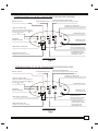
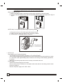
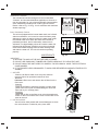
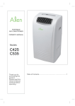
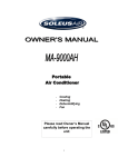
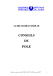
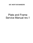
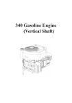
R OOM AIR C ONDITIONE R
US E & C AR E MANUAL
P OR TAB L E TY P E R OOM AIR C ONDITIONE R
MODE L #:
UL and
C UL listed
C
R
LIS TE D
DOC-091R
DOC-091R H
US
P lease read carefully and thoroughly this manual before
operating the unit.
If you still have any difficulties or problems, consult your
dealer for help or
E LE C TR ONIC S .
P lease keep this manual well.
W1
CONTENTS
1.SAFETY RULES............................................................................. 1
2.NAMES OF PARTS.......................................................................... 2
3.ACCESSORIES................................................................................ 2
4.OPERATION PANEL OF THE AIR CONDITIONER........................ 3
5.OPERATING INSTRUCTION FOR THE AIR CONDITIONER ........ 4
6.INSTALLATION............................................................................... 6
7.MAINTENANCE............................................................................... 7
8.TROUBLE SHOOTING.................................................................... 8
SAFETY RULES
1. DO NOT CONNECT UNIT TO ANY AC SOCKET IN DISREPAIR OR WITH
CONNECTIONS.
2. DO NOT USE IN THE FOLLOWING LOCATIONS:
- NEXT TO SOURCE OF FIRE.
- AN AREA WHERE OIL IS LIKELY TO SPLASH.
- AN AREA EXPOSED TO DIRECT SUNLIGHT.
- AN AREA WHERE WATER IS LIKELY TO SPLASH.
- NEAR A BATH, A SHOWER OR A SWIMMING POOL
- IN THE GREEN HOUSE
3. NEVER INSERT YOUR FINGERS OR ANY FOREIGN OBJECTS INTO THE AIR
OUTLET. TAKE SPECIAL CARE TO WARN CHILDREN OF THESE DANGERS.
4. ALWAYS STORE THE UNIT UPRIGHT IN ORDER TO MAINTAIN THE COMPRESSOR IN A PROPER CONDITION.
5. BE SURE TO UNPLUG THE UNIT BEFORE CLEANING.
6. THE HEATER MUST NOT BE LOCATED IMMEDIATELY BELOW A SOCKET
OUTLET.
7. IF THE APPLIANCE IS COVERED, THERE IS A RISK OF OVERHEAT.
8. IF THE SUPPLY TOOL OF THIS APPLIANCE IS DAMAGED, IT MUST BE
REPLACED BY A REPAIR SHOP APPOINTED BY THE MANUFACTURER,
BECAUSE SPECIAL PURPOSE TOOLS ARE REQUIRED.
NOTE: The air-conditioner can be connected only to a supply with system
impedance no more than 0.4582 ohm. In case necessary, please consult your
supply authority for system impedance information.
1
NAMES OF PARTS
OPRATION PANEL
REAR COVER
AIR INLET
FRONT COVER
AIR OUTLET
AIR OUTLET
OUTDOOR
WATER PUMP
DRAIN HOSE
AIR INLET
OUTDOOR
REMOTE CONTROLLER
CASTER
INDOOR
CONTINUOUS
DRAIN HOSE
POWER CORD
SIDE VIEW
FRONT VIEW
AIR INLET
OUTDOOR
REAR VIEW
Fig.1
ACCESSORIES
PARTS :
PARTS NAME :
QUANTITY :
DUCT
1
ADAPTOR A (FOR PERMANENT DUCT
1
MOUNTING)
ADAPTOR B (FOR TEMPORARY DUCT
MOUNTING)
1
WALL PLUG
4
SCREWS
4
ALKALINE BATTERIES
2
REMOTE CONTROLLER
1
WATER PUMP DRAIN HOSE
1
Fig.2
Check all the accessories are included in the package and please refer to the installation instructions
for their usage.
2
OPERATION PANEL OF THE AIR CONDITIONER(COOLING AND HEATING)
DIGITAL DISPLAY
FAN SPEED INDICATOR
COOL/DRY/FAN/HEAT INDICATIOR
Green lamp will light when the mode is selected
WATER FULL INDICATOR
Red lamp will blink when the tank is full
TEMP SETTING BUTTON
Press your desired room temperature
setting by pressing the button
(up)
or button
(down)
POWER INDICATOR
INFRARED
SIGNAL RECEIVER
POWER BUTTON
Turn on/off the unit
MODES BUTTON
Select the operation mode
from COOL.DRY.FAN.HEAT
TIMER ON/OFF INDICATOR
FAN SPEED BUTTON
Select the fan speed from
HIGH.MED or LOW
TIMER ON/OFF BUTTON
Program the on/off timer function
OPERATING PANEL
Fig.3
OPERATION PANEL OF THE AIR CONDITIONER(COOLING ONLY TYPE)
DIGITAL DISPLAY
FAN SPEED INDICATOR
COOL/DRY/FAN INDICATOR
Green lamp will light when the mode is selected
WATER FULL INDICATOR
Red lamp will blink when the tank is full
TEMP SETTING BUTTON
Select your desired room temperature
setting by pressing the button
(up)
or button
(down)
POWER INDICATOR
INFRARED
SIGNAL RECEIVER
POWER BUTTON
Turn on/off the unit
MODES BUTTON
Select the operation mode
from COOL.DRY.FAN.
TIMER ON/OFF INDICATOR
FAN SPEED BUTTON
Press the button to select
the fan speed from
HIGH.MED or LOW
TIMER ON/OFFBUTTON
Program the on/off timer function
OPERATING PANEL
Fig.4
3
OPERATING INSTRUCTING FOR THE AIR CONDITIONER
Before Starting This Unit
1) Select a suitable location, make sure you have easy access to an electrical outlet.
2) Install the Flexible Exhaust Hose and the Adjustable Window Slider Kit as depicted in Fig.5 &
Fig.5a
Fig.5a
Fig.5
NOTE: Step 2 is required only while using the cooling mode
3) Plug the unit into a 115V~60Hz grounded electrical outlet.
4) Make sure the water pump drain hose is correctly installed.
¡¡ 5) Press the on / off button to turn on the unit.
Water pump drain hose
Fig.6
1 BEFORE USE
Dehumidifying and Cooling Operations
- The operating range for cooling operating is 17OC-30OC/63OF-86OF.
- If the cooling or dehumidifying operations have been switched off and need switching on again
in a short time, allow approximately three minutes for the cooling or dehumidifying operations
to resume.
- Make sure the water pump drain hose is correctly connected to the unit.
Power supply:
- Insert the AC Power Plug to a AC socket.
- Do not connect the air conditioner to a multiple socket outlet which is also being used for other
electrical appliance.
- Be sure the power supply is AC 115V~ 60Hz.
4
O
O
O
O
2 COOLING OPERATION (Operating temperature range: 17 C-32 C/63 F-90 F)
- Press the "MODE" button several times until the "COOL" indicator light comes on.
- Press the "TEMP SETTING" buttons " " or " " to select your desired room temperature.
(17OC-30OC/63OF-86OF)
- Press the "FAN SPEED" button to choose the fan speed.
O
O
O
O
3 DEHUMIDIFYING OPERATION (Operating temperature range: 13 C-32 C/55 F-90 F)
- Press the "MODE" button several times until the "DRY" indicator light comes on.
- The fan will run at a fixed speed at this setting.
- Keep windows and doors closed for the best dehumidifying effect.
- Do not put the duct to window.
4 HEATING OPERATION (Cooling only type without heat feature)
O
O
O
O
(Operating temperature range:5 C-30 C/41 F-86 F)
- Press the "MODE" button several times until the "HEAT" indicator light comes on.
- Press the "TEMP SETTING" buttons " " or " " to select your desired room temperature.
(17OC-30OC/63OF-86OF)
- Press the "FAN SPEED" button to choose the fan speed.
- Do not put the duct to window.
5 FAN OPERATION
- Press the "MODE" button several times until the "FAN " indicator light comes on.
- Press the "FAN SPEED" button to choose the fan speed.
- Do not put the duct to window.
6 TIMER OPERATION
Setting the on timer:
- Press the "TIMER ON" button when the air conditioner is off. Select the time you need the unit
start to operate.
- The Operation Paned Window will display "ON"
- The starting time is adjustable from 0.00 to 24.
Setting the off timer:
- Press the "TIMER OFF" button when the air conditioner is on. Select the time you need the unit
turn off. The Operation Panel Window will display "OFF".
- The turning off time is adjustable from 0.00 to 24.
7 WATER PUMP DRAINAGE
- Connect the water pump drain hose to the unit before operate. When the water level of the internal
water tank reaches a predetermined level, the water pump will be activated and drain the
condensed water outside through the connected drain hose. The maximum delivery lift is 3.5m.
(Under this condition, attach the rubber blockage to the back hole to prevent continuous drainage.)
8 CONTINUOUS DRAINAGE
- When you plan to leave this unit unused for a long time, remove the rubber blockage form the back
hole and attach a section of the continuous drain hose to drain hose connector. All the water in the
water tank would drain outside through the drain hose. (Under this condition, the water pump is not
activated.)
5
INSTALLATION
1 IMPORTANT:
Install the mobile ir conditioner in a flat and spacious location
where the air outlets will not be covered up. A minimum
clearance of 30cm from a wall or other obstacles should
be kept. The appliance shall not be used in the laundry.
The plug shall accessible after appliance is positioned.
Wiring shall be done according to National rules.
30c
m
30
cm
Fig.7
2 DUCT MOUNT INSTRUCTIONS:
Exhaust Air Oulet
Duck
Fig.8
A) TEMPORARY1. Attach one end of the duct to the exhaust air outlet of the
mobile air condition, first fit the left side of the duct on the
exhaust air panel, then the right side duct. Push it
downwards, be sure to fix thoroughly. (See the figures)
2. Attach the other end of the duct to adaptor B.
3. Put the end of duct to a nearby window.
B) PERMANENT1. Attach one end of the duct to the exhaust air outlet of the
mobile air conditioner. According to the arrow direction,
first fit the left side of the duct on the exhaust air panel,
then the right side duct. Push it downwards, be sure to fix
thoroughly. (See the figures)
2. Install the adaptor A onto the wall by using 4 wall plug and
screws, be sure to fix thoroughly. (See the figures)
3. Attach the other end of the duct to adaptor A.
4. Cover the hole using the adaptor cap when not in use.
Adapter A
Skruer
Rawlplugs
max 120CM
min 30CM
Fig.9
The duct can be compressed or extended between 500mm
and 2000mm, but it is desirable to keep the duct length to a
minimum.
IMPORTANT:
DO NOT OVER BEND THE DUCT (SEE FIGURE)
6
Fig.10
Window Kit Installation
Your window kit has been designed to fit most standard
Vertical and horizontal window applications, However, it
may be necessary for you to improvise/modify some aspects
of the installation procedures for certain types of window.
Please refer to Fig. 11 & Fig. 11a for minimum and maximum
window openings.
Drain Tank Safety Feature
This unit is equipped with a internal water tank, two full-safe
switch mechanisms, one is used to control the water pump
drainage, the other is used to monitor the water level inside
the internal water tank. When the water level reaches a
predetermined level, the full-safe switch mechanism is
activated. The digital display shows P1 and the water full
indicator light illuminates. Carefully move the unit outside,
remove the rubber blockage from the back drainage hole
and drain the water off. The unit will continue operating
properly.
MAINTENANCE
Horizontal
window
Window Slider Kit
Minimum:67.5cm(2.22ft).
Maxmum:123cm(4.04ft).
Fig.11
Horizontal
window
Window Slider Kit
Minimum:67.5cm(2.22ft).
Maxmum:123cm(4.04ft).
Fig.11a
IMPORTANT:
1) BE SURE TO UNPLUG THE UNIT BEFORE CLEANING.
2) DO NOT USE GASOLING, THINNER OR OTHER CHEMICALS TO CLEAN THE UNIT.
3) DO NOT WASH THE UNIT DIRECTLY UNDER A TAP OR USING A HOSE. THE ELECTRICAL
CAUE DANGER.
4) IF THE POWER CORD IS DAMAGED, IT SHOULD BE REPAIRED BY MANUFACTURE OR ITS
AGENCY.
1 AIR FILTER
- Clean the air filter at least once every two weeks to
prevent inferior fan operation because of dust.
- Removal
Pull out the filter cover and remove the air filter from the
filter cover.
- Cleaning
Wash the air filter by immersing it gently in warm water
(about 40OC/104OF) with a neutral detergent. Rinse the
filter and dry it in a shady place.
- Mounting
Attach the air filter to the filter cover using the attachment
hooks on the inner surface of the cover. Put the filter cover
back to the unit.
2 UNIT ENCLOSURE
- Use a lint-free cloth soaked with neutral detergent to clean
the unit enclosure. Finished by a dry clean cloth.
Fig.12
7
TROUBLE SHOOTING
TROUBLES
POSSIBLE CAUSES
SUGGEST REMEDIES
1. UNIT DOES NOT
- Water full indicator blinks, water tank
Dump the water in the water tank.
START WHEN
is full.
PRESSING 1/0 BUTTON
- Room temperature is higher than
Reset the temperature.
the set temperature.(Heating mode)
- Room temperature is lower than
Reset the temperature.
the set temperature.(Cooling mode)
2. NOT COOL ENOUGH
- The windows or doors in the room
are not closed.
- There are heat sources inside the
Make sure all the windows and
doors are closed.
Remove the heat sources if possible.
room.
- Exhaust air duct is not connected or
blocked.
3. POWER SHUT OFF AT
HEATING MODE
Connect the duct and make
sure it can function properly.
- Temperature setting is too high.
Decrease the set temperature.
- Air filter is blocked by dust.
Clean the air filter.
- The automatic over heat protection
Switch on again after the unit has cool down.
function. When the temperature at
the air outlet exceed 70OC/158OF,the
device will stop.
4. NOISY OR VIBRATION
- The ground is not level or not flat
enough.
5. GURGLING SOUND
- The sound comes from the flowing
of the refrigerant inside the
air-conditioner.
8
Place the unit on a flat, level
ground if possible.
It is normal.
L imited Warranty
DAE WOO E LE C T R ONIC S AME R IC A, INC . warrants the following P ortable room airconditioner to be free from defective material and workmans hip and agrees to remedy
any s uch defect or to furnis h a new part (at the C ompanyÕs option) in exchange for any
part of any unit of its manufacture which under normal ins tallation, us e and s ervice
dis clos ed s uch defect, provided the unit is delivered by the owner to s tore or dealer
where purchas ed or Daewoo authorized s ervice center. T o es tablis h and receive
warranty s ervice at our s tore, dealer or our authorized s ervice center, a s ales receipt
or bill of s ales is required for proof of purchas e.
T his warranty does not extend to any of our electronic products which have been
s ubjected to mis us e, neglect, accident, incorrect wiring not our own, improper
ins tallation, unauthorized modification, or to us e in violation of ins tructions furnis hed by
us , nor units which have been repaired or altered outs ide of our factory, nor to cas es
where the s erial number thereof has been removed, defaced, or changed.
T his warranty is in lieu of all warranties expres s ed or implied and no repres entative or
pers on is authorized to as s ume for us any other liability in connection with the s ales of
our electronic products .
Over the counter exchange for units that are initially defective. Initial defective is
des cribed as when the dealer opens the unit and finds that it is inoperative or an
individual cus tomer opening a new unit and finding that it is initially defective. T his unit
may be returned to the factory by the dealer for exchange. Under no circums tances
will an individual cus tomer be permitted to return defective unit directly to factory.
E xchange mus t be directly with the dealer. When this unit is returned to dealer, a copy
of the purchas e evidence s tating the date of purchas e is to be put in the individual box
for dealerÕs further control with the factory.
MODE L
P AR T S
LAB OR
C OMP R E S S OR
DOC -091R
DOC -091R H
1 year
1 year
5 years
Note: T he warranty s ervice center lis t is cons tantly changing with the addition of our
current qualified s ervice centers . If there is inadequate or no local s ervice facility,
s ubject individual cus tomer will call DAE WOO on the toll free number
1-800-DA E WOO8(1-800-323-9668) to be provided with further informations .