1
CY3270
PSoC® FirstTouch™ Guide
Document # 001-15945 Rev. **
Cypress Semiconductor
198 Champion Court
San Jose, CA 95134-1709
Phone (USA): 800.858.1810
Phone (Intnl): 408.943.2600
http://www.cypress.com
Copyrights
Copyrights
© Cypress Semiconductor Corporation, 2007. The information contained herein is subject to change without notice. Cypress
Semiconductor Corporation assumes no responsibility for the use of any circuitry other than circuitry embodied in a Cypress
product. Nor does it convey or imply any license under patent or other rights. Cypress products are not warranted nor
intended to be used for medical, life support, life saving, critical control or safety applications, unless pursuant to an express
written agreement with Cypress. Furthermore, Cypress does not authorize its products for use as critical components in lifesupport systems where a malfunction or failure may reasonably be expected to result in significant injury to the user. The
inclusion of Cypress products in life-support systems application implies that the manufacturer assumes all risk of such use
and in doing so indemnifies Cypress against all charges.
PSoC Designer™, Programmable System-on-Chip™, and PSoC Express™ are trademarks and PSoC® is a registered
trademark of Cypress Semiconductor Corp. I²C is a registered trademark of Philips Electronics. All other trademarks or registered trademarks referenced herein are property of the respective corporations.
Any Source Code (software and/or firmware) is owned by Cypress Semiconductor Corporation (Cypress) and is protected by
and subject to worldwide patent protection (United States and foreign), United States copyright laws and international treaty
provisions. Cypress hereby grants to licensee a personal, non-exclusive, non-transferable license to copy, use, modify, create
derivative works of, and compile the Cypress Source Code and derivative works for the sole purpose of creating custom software and or firmware in support of licensee product to be used only in conjunction with a Cypress integrated circuit as specified in the applicable agreement. Any reproduction, modification, translation, compilation, or representation of this Source
Code except as specified above is prohibited without the express written permission of Cypress.
Disclaimer
CYPRESS MAKES NO WARRANTY OF ANY KIND, EXPRESS OR IMPLIED, WITH REGARD TO THIS MATERIAL,
INCLUDING, BUT NOT LIMITED TO, THE IMPLIED WARRANTIES OF MERCHANTABILITY AND FITNESS FOR A PARTICULAR PURPOSE. Cypress reserves the right to make changes without further notice to the materials described herein.
Cypress does not assume any liability arising out of the application or use of any product or circuit described herein. Cypress
does not authorize its products for use as critical components in life-support systems where a malfunction or failure may reasonably be expected to result in significant injury to the user. The inclusion of Cypress’ product in a life-support systems application implies that the manufacturer assumes all risk of such use and in doing so indemnifies Cypress against all charges.
Use may be limited by and subject to the applicable Cypress software license agreement.
2
CY3270 PSoC® FirstTouch™ Guide, Document # 001-15945 Rev. **
Contents
1. Introduction
1.1
1.2
Document History ........................................................................................................6
Document Conventions ...............................................................................................6
2. Getting Started
2.1
2.2
2.3
2.4
2.5
7
Install Hardware and Run the CapSense Touch Sensing Design ...............................7
Install Software ............................................................................................................7
Run the Temperature, Light, and CapSense Proximity Sensing Designs ...................7
FTMF Expansion Card Demonstrations ......................................................................8
2.4.1 CapSense Touch Sensing Demonstration (default) .........................................9
2.4.2 Temperature Sensing Demonstration.............................................................10
2.4.3 Light Sensing Demonstration .........................................................................11
2.4.4 CapSense Proximity Sensing Demonstration ................................................12
Exploring the FTMF Expansion Card Demonstration Projects ..................................13
2.5.1 Opening a Demonstration Project ..................................................................13
2.5.2 Modifying the New Project .............................................................................13
2.5.3 Simulating the Project ....................................................................................14
2.5.4 Building the New Project ................................................................................14
2.5.4.1 Selecting the Target Device.............................................................14
2.5.4.2 Specifying the Target Device Pinout................................................14
2.5.5 Programming the Project ...............................................................................14
2.5.6 Verifying the Results ......................................................................................15
2.5.7 Understanding the Results .............................................................................15
2.5.8 Important Things to Remember .....................................................................15
3. Technical Reference
3.1
3.2
3.3
5
17
FTPC Bridge Details ..................................................................................................17
Expansion Card Overview .........................................................................................19
Expansion Card Details .............................................................................................19
3.3.1 FirstTouch MultiFunction Expansion (FTMF) Card.........................................19
CY3270 PSoC® FirstTouch™ Guide, Document # 001-15945 Rev. **
3
Contents
4
CY3270 PSoC® FirstTouch™ Guide, Document # 001-15945 Rev. **
1.
Introduction
The PSoC® FirstTouch™ Kit includes a USB interface dongle, referred to as the FTPC bridge, and a
multifunction expansion card, referred to as the FTMF Expansion Card. The FTMF Expansion Card
demonstrates a variety of applications using ‘PSoC Powered Peripherals’. The FTMF Expansion
Card connects to the bridge through the bridge’s built-in 8x2 pin expansion port. As the name
implies, the FTPC bridge forms the connection between the FTMF Expansion Card and the various
PC applications that control and communicate with the FTMF Expansion Card.
The FTPC bridge portion of the kit contains a programmed Cypress CY8C24894 PSoC that performs all of the USB and expansion card interface functions. The firmware that is run by this PSoC
performs the primary functions listed.
■
Functions as a USB physical and logical interface
■
Provides PSoC MiniProg emulation for In System Serial Programming (ISSP) of the expansion
cards
■
Provides communications with the PSoC programming utility
■
Performs HID data channel communications
■
Performs expansion card I2C™ communications
■
Performs expansion card SPI communications
There are no other active components inside of the FTPC bridge. All of these interfaces run on a single PSoC device. Future projects for the FirstTouch Kit allow you to modify the FTPC firmware and
try some USB Interface designs of your own.
The FirstTouch expansion card connects to the FTPC bridge through the bridge’s 8x2 pin expansion
port. This expansion port provides all of the necessary signals to program the host PSoC on the
expansion card. The expansion port also provides power, ground, and I2C or SPI communications to
and from the expansion card host PSoC and PC.
Since the FirstTouch expansion card has a dedicated host PSoC, once programmed with your
design, the expansion cards can operate either detached from the FTPC bridge in standalone mode
or connected to your system hardware. Obviously, it is necessary to provide power and ground for
the expansion card to operate in either of these two arrangements.
There are four unused analog or digital GPIO pins on the FTPC port and four unused analog or digital GPIO pins on the expansion card. This allows you to create custom designs and connect signals
you want to the FTPC bridge or the FirstTouch expansion cards.
CY3270 PSoC® FirstTouch™ Guide, Document # 001-15945 Rev. **
5
Introduction
1.1
Document History
This section serves as a chronicle of the CY3270 PSoC® FirstTouch™ Guide.
CY3270 PSoC® FirstTouch™ Guide History
Release
Date
Firmware
Revision
Guide
Version
Originator
09/05/07
See Note a
**
ARI
a
1.2
Description of Change
This guide is a new document.
PSoC Express 3.0 generates the firmware.
Document Conventions
This guide uses the Courier New font to distinguish file location and source code examples from
regular text. File names are presented in italics text. Keyboard commands are bolded.
6
CY3270 PSoC® FirstTouch™ Guide, Document # 001-15945 Rev. **
2.
2.1
Getting Started
Install Hardware and Run the CapSense Touch Sensing Design
To install the kit hardware and run the CapSense touch sensing design, do as follows:
1. Remove both end caps from the FTPC Bridge and then connect the FTMF Expansion Card into
the header of the FTPC Bridge such that ‘Cypress Perform’ is visible on both boards. Insert the
assembled kit into your computer USB port. Select Cancel in the ‘Found New Hardware Wizard’
window that appears.
2. Slide finger along the CapSense Touch Sensing slider found on the furthest point away from your
computer. Notice the LED variation based on the position of your finger on the slider. This is the
CapSense Touch Sensing Design working right out of the box.
2.2
Install Software
To install the software, proceed as follows:
1. Remove the PSoC FirstTouch Starter Kit from your computer USB port.
2. Insert the FirstTouch Kit CD-ROM into your computer. The CD is designed to ‘Auto Run’ and the
PSoC Express installation menu should appear. Alternatively, you can double click on the Autorun.exe file in the root directory of the CD-ROM to get the installation menu.
3. From the PSoC Express installation menu, select Install PSoC Programmer. When that is complete, select Install .NET Framework. When that is complete, select Install PSoC Express and
then select Express Pack 1 for PSoC Express in that order (You can also find the latest software versions at www.cypress.com/FirstTouch). For each installation, follow the instructions
issued by the installation wizard. To copy the kit documents to your computer, select Install FirstTouch kit documentation. This copies the documents to the C:\Cypress\CY3270 directory.
4. Once the software installations are complete, click Exit in the PSoC Express Installation Menu.
5. Insert the PSoC FirstTouch Starter Kit (FTPC Bridge and FTMF Expansion Card connected) into
your computer USB port. In the ‘Found New Hardware Wizard’ window, select No, not this time.
In the second ‘Found New Hardware Wizard’ window, select Install the software automatically.
Alternatively, direct the New Hardware wizard to \..\Program Files\Cypress MicroSystems\PSoC Programmer\drivers\ on your computer. If prompted with a 'Driver Verification'
message, click Continue Anyway.
2.3
Run the Temperature, Light, and CapSense Proximity Sensing
Designs
To run the temperature, light, and CapSense proximity sensing designs do as follows:
1. Launch PSoC Express.
2. From the Express Design Catalog, expand the ‘CY3270-PSoC FirstTouch Kit’ folder, and double
click on one of the projects and re-name it.
CY3270 PSoC® FirstTouch™ Guide, Document # 001-15945 Rev. **
7
Getting Started
3. From the top menu bar, click Build and then select Generate/Build {your project name}
Project. Click Next in the following two screens.
4. From the top menu bar, click Program and then select Programmer. Within the Programmer
window, select Port > FirstTouch and set the Programming Mode button to Reset. Select the
File Load button. Within the ‘Open’ window, double-click {your project name}.hex located in
{your project folder}\{your project name}\output under the default \..\My
Documents folder or the alternate folder you designated. Then, click the Program button.
5. Once programming completes successfully, verify the project operation by doing as follows:
a. Temperature Sensing–the LED color varies based on changes in the ambient temperature
(the buzzer sounds at extreme temperatures).
b. Light Sensing–the LED intensity varies based on changes in the ambient light.
c. CapSense Proximity Sensing–the LED color varies based on your hand’s proximity to the
board.
2.4
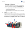
FTMF Expansion Card Demonstrations
The FTMF Expansion Card provided in your kit is capable of supporting a variety of demonstrations.
Each demonstration has an associated PSoC Express project and data sheet that describes the
operation and usage of each of the demonstrations in detail. Since the FTMF expansion card has its
own PSoC, you can remove it from the FTPC bridge and insert it into your target hardware or other
development platform. In order to observe each of the various FTMF demonstrations, it is necessary
to reprogram the FTMF card with the appropriate demonstration firmware. For more details refer to
the Technical Reference chapter on page 17.
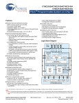
Figure 2-1. FTMF Expansion Card
Proximity
Antenna
Buzzer
Temperature
Sensor
CapSense
Slider
Light Sensor
8
LED Display
CY3270 PSoC® FirstTouch™ Guide, Document # 001-15945 Rev. **
Getting Started
2.4.1
CapSense Touch Sensing Demonstration (default)
The pre-programmed CapSense Touch Sensing demonstration shows how to use the CapSense
Touch Sensing slider to control LED color. Run your finger across the CapSense Touch Sensing
slider (see Figure 2-1) and notice how the color of the LED color changes. The CY8C21434 PSoC
that resides on the FTMF Expansion Card detects your finger’s position on the CapSense Touch
Sensing slider and controls the LEDs output.
Figure 2-2. CapSense Touch Sensing Demo Schematic
CY3270 PSoC® FirstTouch™ Guide, Document # 001-15945 Rev. **
9
Getting Started
2.4.2
Temperature Sensing Demonstration
The temperature sensing demonstration shows how to use a temperature sensor to control LED
color. Follow the CapSense Touch Sensing based guidelines in section 2.5 Exploring the FTMF
Expansion Card Demonstration Projects to simulate, build, and program the FTMF Expansion Board
with the temperature sensing demonstration. Touch the temperature sensor (see Figure 2-1) and
notice how the LED color changes. Removing your finger leads to the LED color slowly reverting
back to its initial state. The CY8C21434 PSoC that resides on the FTMF Expansion Card detects the
temperature and controls the LEDs output.
Figure 2-3. Temperature Sensing Demo Schematic
10
CY3270 PSoC® FirstTouch™ Guide, Document # 001-15945 Rev. **
Getting Started
2.4.3
Light Sensing Demonstration
The light sensing demonstration shows how to use an ambient light sensor to control LED intensity.
Follow the CapSense Touch Sensing based guidelines in section 2.5 Exploring the FTMF Expansion
Card Demonstration Projects to simulate, build, and program the FTMF Expansion Board with the
ambient light sensing demonstration. Cover the light sensor (see Figure 2-1 on page 8) with the
palm of your hand and notice how the intensity of the LED changes. Removing your palm leads to
the LED intensity reverting back to its initial state. The CY8C21434 PSoC that resides on the FTMF
Expansion Card detects the ambient light and controls the LEDs output.
Figure 2-4. Light Sensing Demo Schematic
CY3270 PSoC® FirstTouch™ Guide, Document # 001-15945 Rev. **
11
Getting Started
2.4.4
CapSense Proximity Sensing Demonstration
The CapSense proximity sensing demonstration shows how to use a proximity sensor to control
LED color.
The proximity detector requires the use of a Proximity Antenna and can sense an object with approximately 2–3 inches of range. In the FirstTouch Kit, this sense antenna is formed by attaching the provided wire into the pin socket labeled PRX1 as shown in Figure 2-1 on page 8. Note Upon power up,
the FTMF will establish a baseline reading of the Proximity Antenna. It is therefore necessary to connect the Proximity Antenna prior to plugging in the FirstTouch kit.
The project is setup to recalculate this baseline approximately every 30 seconds. Also notice how
the shape and position of the wire affects the demonstration operation and the proximity sensing distance.
Figure 2-5. CapSense Proximity Sensing Demo Schematic
Follow the CapSense Touch Sensing based guidelines in section 2.5 Exploring the FTMF Expansion
Card Demonstration Projects to simulate, build, and program the FTMF Expansion Board with the
CapSense proximity sensing demonstration. Slowly approach the CapSense proximity sensor
(depicted in Figure 2-1 on page 8) with your fingers and notice how the color of the LED color
changes. Removing your fingers leads to the LED color slowly reverting back to its initial state. The
CY8C21434 PSoC that resides on the FTMF Expansion Card detects the relative proximity of your
fingers to the FTMF Expansion Card and controls the LEDs output.
12
CY3270 PSoC® FirstTouch™ Guide, Document # 001-15945 Rev. **
Getting Started
2.5
Exploring the FTMF Expansion Card Demonstration Projects
To explore the various FTMF Expansion Card projects, do as follows:
1. Remove the FTPC Bridge from the USB port on the PC.
2. Connect the FTMF Expansion Card into the header of the FTPC Bridge such that ‘Cypress Perform’ is visible on both the FTPC Bridge and the FTMF Expansion Card.
3. Once the two are properly connected, insert the complete FirstTouch Kit back into the USB port.
2.5.1
Opening a Demonstration Project
To run demonstration project, do as follows:
1. Launch the PSoC Express Development Suite. Once PSoC Express loads, the Express Design
Catalog panel is displayed in the Start Page pane.
2. From the Express Design Catalog, expand the ‘CY3270-PSoC FirstTouch Kit’ folder.
3. Click the CapSense Touch Sensing Slider entry. A design data sheet appears in the Express
Helper panel. This data sheet describes all of the details relating to this particular project.
Since this is a Design Catalog project, you cannot change this project directly. Instead, rename the
project and save it to a new location. This makes a copy of the project that you are free to change.
4. Double-click the MultiFunction Board CapSense Touch Sensing Slider entry. A dialog box
appears prompting you for a project name and location. Browse to the location where you want to
save this project, give it a name, and click OK.
PSoC Express ‘clones’ the contents of the MultiFunction Board CapSense Slider demonstration
project and the Project Design window appears.
Note Other documentation included with the PSoC Express Development Suite gives detailed
descriptions about the operation of PSoC Express.
2.5.2
Modifying the New Project
One example of modifying the demonstration project is as follows:
1. Place the cursor over the LED icon that appears on the Design window.
2. Right click and select Transfer Function.
3. From the Transfer Function window, select the Edit Transfer Logic radio button.
4. Click OK from the dialog box that appears.
Once the Priority Encoder Transfer Function window appears, notice the details of how the
CapSense Slider affects the LEDs.
For this simple demonstration, you can change the order of the LEDs.
1. Left click in the LED_State_Blue area and delete the text in the ‘then’ field.
2. Right click to get menu options, then double-click on LED_State_Red from the list.
3. Left click in the original LED_State_Red area and delete the test in the 'then' field.
4. Right click to get the options, then double-click on LED_State_Blue from the list.
5. Click OK to continue.
CY3270 PSoC® FirstTouch™ Guide, Document # 001-15945 Rev. **
13
Getting Started
2.5.3
Simulating the Project
Simulation is a very useful tool. You can run the simulation on the project you defined; if the results
are not what you expected, you can go and change the design until you get the results you want.
This saves time and effort by allowing evaluation of your design's operation prior to programming the
hardware.
Once you have made changes to your project, click the Simulation tab to proceed to the PSoC
Express Design Simulator to verify that your design does what you intended. For instance, type 23 in
the CSD Properties ‘Current Value’ box and see the ‘Red’ come up in the LED ‘Current Value’ box.
This matches the transfer function logic designed into this project.
If the behavior meets your expectations, you are ready for the next step. If not, you can go back to
the Design tab, edit the Transfer Function logic, and return to Simulation to verify your changes.
Other PSoC evaluation and development kits implement monitoring and tuning to change project
variables in real-time and then dynamically change the driver configuration.
2.5.4
Building the New Project
Once you are confident that your design is correct, from the top menu bar click Build and then select
Generate/Build {your project name} Project.
2.5.4.1
Selecting the Target Device
PSoC Express displays a Device Selection window that allows you to select a ‘target’ device for your
project. All FTMF Expansion Card projects must use the 32-pin CY8C21434 as the device target.
Select this device from the list and click Next. Express then continues to compile your project.
2.5.4.2
Specifying the Target Device Pinout
The Express Pin Editor window appears. This window allows you to drag and drop the various
project signals to the PSoC device IO pins. For this project, no changes are made to the pin assignments. Click Next to continue.
Note If you are creating your own project for the FTMF card, refer to the Figure 3-4 on page 21 for a
schematic and Table 3-1 on page 22 for the pin connections before proceeding beyond this point.
Once PSoC Express completes building your design, the BOM/Schematic window appears. Use this
as an error-checking step to confirm that all of the IO pins did not move and are exactly where you
intended.
2.5.5
Programming the Project
To program the project to the FTMF Expansion Card, do as follows:
1. From the top menu bar, click Program and then select PSoC Programmer. The PSoC Programmer utility launches.
2. On the Programmer GUI, select Port > FirstTouch.
3. Ensure that the Device Family is set to 21X34 and the Device Type is CY8C21434-24LFXI (this is
the PSoC on the FTMF Expansion Card).
4. Set the Programming Mode button to Reset and then click the Program button.
The Programmer utility begins programming the project’s HEX file to the FTPC bridge; the bridge in
turn re-programs the PSoC on the FTMF Expansion Card.
14
CY3270 PSoC® FirstTouch™ Guide, Document # 001-15945 Rev. **
Getting Started
2.5.6
Verifying the Results
Once the programming completes successfully, the FTPC Bridge resets the FTMF Expansion Card
and begins running your project on the FTMF Expansion Card. Verify the project as follows:
Did the changes that were made take effect?
If not, return to the PSoC Express Design Editor, make any necessary changes, and reprogram your
FTMF Expansion Card again.
2.5.7
Understanding the Results
The steps described throughout the section Exploring the FTMF Expansion Card Demonstration
Projects on page 13 demonstrate the entire flow of PSoC Express, PSoC Programmer, and the FirstTouch Kit. You now know the process and PSoC Express Design Flow to make your own projects or
to load another FTMF Expansion Card demonstration project from the Express Design Catalog.
2.5.8
Important Things to Remember
There are a few important points to remember when working with the FirstTouch kit and projects.
1. Use the FTMF Expansion Card schematic, pin assignment tables, or both when creating a
project. Failure to do so almost certainly guarantees that your project will not behave as planned.
2. Select the proper device to use as the ‘host’ on the particular expansion card with which you are
working.
3. Always use the ‘Reset’ programming mode when programming through the FTPC bridge.
CY3270 PSoC® FirstTouch™ Guide, Document # 001-15945 Rev. **
15
Getting Started
16
CY3270 PSoC® FirstTouch™ Guide, Document # 001-15945 Rev. **
3.
Technical Reference
3.1
FTPC Bridge Details
The FTPC Bridge is the interface bridge between the expansion cards, your PC, and the various
applications such as PSoC Express™, PSoC Designer™, and the PSoC Programmer utility.
Since the FTPC Bridge enumerates as a special type of ‘combo device’ that contains a PSoC MiniProg interface, the standard PSoC Programmer utility can identify and communicate with the FTPC
bridge. This ensures that your FirstTouch Kit is automatically compatible with both PSoC Express
and PSoC Designer.
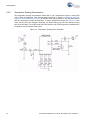
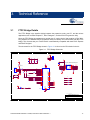
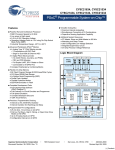
The schematic for the FTPC Bridge shown in Figure 3-1 is found on the CD included in the kit.
Figure 3-1. FTPC Bridge Schematic
5
4
3
2
1
V50
J1
XRES894
CLK894
DAT894
V50
D
1
2
3
4
5
D
ISSP894
C2
0805
V50
0.1 uFd
C3
0805
0.1 uFd
C4
0805
A
V50
ISSP-RADON
+ C5
10 uFd 10v
0.1 uFd
A
+ C1
22 uFd 10v
NO LOAD
8x2 0.100" FEMALE Expansion Receptacle
J3
F1
350mA
J2
1
2
3
4
5
6
R4
R5
27
27
0805
21
20
DM
DP
36
XRES
8X2 PIN RECPT RA
R3
0805
0805
100
Zero
100K
P02
P03
P04
P05
ISSP_XRES
ISSP_CLK
45
54
46
53
47
52
48
51
P0_0
P0_1
P0_2
P0_3
P0_4
P0_5
P0_6
P0_7
P3_0
P3_1
P3_2
P3_3
P3_4
P3_5
33
10
34
9
35
8
P3_7
7
25
18
26
17
27
16
28
15
P1_0
P1_1
P1_2
P1_3
P1_4
P1_5
P1_6
P1_7
P4_0
P4_1
P4_2
P4_3
P4_4
P4_5
P4_6
P4_7
37
6
38
5
39
4
40
3
41
2
42
1
43
56
44
55
P2_0
P2_1
P2_2
P2_3
P2_4
P2_5
P2_6
P2_7
P5_0
P5_1
P5_2
P5_3
P5_4
P5_5
P5_6
P5_7
29
14
30
13
31
12
32
11
TP0
P7_0
P7_7
24
23
LED_ALIVE
0805
ISSP-RADON
DAT894
CLK894
0805
C6
SPI_MISO
R16
SDA_MOSI
R15
SCL_SCLK
R14
Zero
0805
Zero
0805
0.01 uFd
Zero
0805
DETECT
B
TYPE
R2
R9
P05
C
100K
GPIO5
NO LOAD
R10
P04
NO LOAD
R11
P03
GPIO4
TP2
TP4
NO LOAD
R12
P02
GPIO3
B
TP6
GPIO2
0805
R1
100K
0805
ISSP_DAT
SPI_nSS
DETECT
SDA_MOSI
SCL_SCLK
GPIO5
GPIO4
GPIO3
GPIO2
0805
100
R8
2
4
6
8
10
12
14
16
0805
R7
USB A RA PLUG SMD
R6
DM
DP
XRES894
0805
ISSP-RADON
0805
VBUS
DM
DP
GND
S1
S2
0805
C
VLOCAL
VEXP_IN
VEXP_OUT
GND
ISSP_XRES SDA-MOSI
ISSP_CLK SCL-SCLK
ISSP_DAT
GPIO5
EXP_TYPE
GPIO4
MISO
GPIO3
SPI_nss
GPIO2
0805
U1
22
49
Resettable Fuse
1
3
5
7
9
11
13
15
ISSP_XRES
ISSP_CLK
ISSP_DAT
TYPE
SPI_MISO
SPI_nSS
VDD1
VDD2
1206L
V50
NO LOAD
D1
1
RADIAL
2
R13
1K
GND1
GND2
EPAD
V50
LED_ALIVE
CY8C24894 QFN56
19
50
57
0805
LED Blue
A
A
PCB: PDCR-9403
CYPRESS SEMICONDUCTOR © 2007
Title
FIRST TOUCH PC BRIDGE
Size
B
Date:
5
4
3
CY3270 PSoC® FirstTouch™ Guide, Document # 001-15945 Rev. **
2
Document Number
REF-14210
Thursday, June 21, 2007
Rev
**
Sheet
1
of
1
1
17
Technical Reference
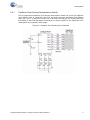
Noticed that the CY8C24894 PSoC device is the only active component in the entire circuit. This single PSoC handles all communications between the applications, USB, and expansion card interfaces.
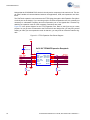
The FirstTouch expansion card connects to the FTPC bridge through the 8x2 Expansion Port (this is
a built-in port on the bridge). If you are using only the FirstTouch expansion card, it is generally not
necessary to understand everything about this expansion port or the signals that it contains. By
attaching an expansion card, all of the necessary connections are made.
Figure 3-2 is the pinout diagram for the FTPC Expansion Port. Refer to this figure as you create
projects. As you get more accustomed to the FirstTouch Kit and design flow, you may find yourself
wanting to make your own expansion cards. At that time, you may want to review the interface signals.
Figure 3-2. FTPC Expansion Port Pinout Diagram
V50
A
+ C1
22 uFd 10v
8x2 0.100" FEMALE Expansion Receptacle
J3
1
3
5
7
9
11
13
15
ISSP_XRES
ISSP_CLK
ISSP_DAT
TYPE
SPI_MISO
SPI_nSS
VLOCAL
VEXP_IN
VEXP_OUT
GND
ISSP_XRES SDA-MOSI
ISSP_CLK SCL-SCLK
ISSP_DAT
GPIO5
EXP_TYPE
GPIO4
GPIO3
MISO
SPI_nss
GPIO2
2
4
6
8
10
12
14
16
DETECT
SDA_MOSI
SCL_SCLK
GPIO5
GPIO4
GPIO3
GPIO2
8X2 PIN RECPT RA
18
100K
R2
0805
0805
R3
100K
CY3270 PSoC® FirstTouch™ Guide, Document # 001-15945 Rev. **
Technical Reference
3.2
Expansion Card Overview
The FirstTouch expansion card is designed to plug and play with the FTPC bridge. All power for the
included expansion cards is provided by the FTPC bridge directly from the USB bus. No other power
supply is necessary when an expansion card is connected to the FTPC bridge. Connection to the
FTPC Expansion Port is through the 8x2 or 5x2 pin header on the expansion card.
The FirstTouch expansion cards have a dedicated host PSoC device installed. The particular PSoC
installed was chosen to act as an example as to which PSoC is most suitable for the types of applications that the particular expansion card supports. This also makes it easier to transfer your design
from the FirstTouch kit to your hardware.
By having a dedicated host PSoC, you can program then remove the expansion card from the FTPC
bridge. Once removed, it operates in a standalone mode or connects to your system level hardware.
This creates a design that provides ‘PSoC Powered Peripherals’ and quickly integrate them into your
system. Before doing so, it is important to review the schematic for the particular expansion card, to
determine the proper power and ground connections and voltage levels.
The expansion card contain a variety of peripheral components that allow you to experiment with
many different sensors and signal types. Each of the sensors use dedicated host PSoC IO pins.
Therefore, it is important to note which pins connect the various sensors to the host PSoC. These
details are provided in the expansion card specific portion of this guide.
3.3
Expansion Card Details
This section provides details for the expansion cards included with the FirstTouch Kit. Future expansion cards will include additional documentation and demonstration projects that are specific to their
operation and configuration.
3.3.1
FirstTouch MultiFunction Expansion (FTMF) Card
The FTMF Expansion Card contains a CY8C21434 PSoC that acts as the ‘host’ for various demonstrations. The FTMF Expansion Card has hardware to support the following PSoC powered peripheral applications:
■
CapSense ‘Touch Button’
■
CapSense ’7-Element Touch Slider’
■
CapSense ’Non-Touch / Proximity Detection’
■
Ambient light-level detection
■
Thermistor-based temperature measurement
In addition to the above input sensors, the FTMF card also provides the following output devices:
■
Red-Green-Blue triple LED cluster
■
Audible magnet transducer or speaker, or both
■
I2C digital communications
■
Four unused A/D GPIO lines for user functions
CY3270 PSoC® FirstTouch™ Guide, Document # 001-15945 Rev. **
19
Technical Reference
The dedicated sensors and output devices on the FTMF Expansion Card are there to help you
quickly evaluate and experiment with a variety of PSoC applications, without having to build any
hardware. Your PSoC Express or PSoC Designer project completely determines the remaining
FTMF Expansion Card functions. Included in the kit installation are demonstration projects that use
the following input sensors:
■
CapSense slider
■
Temperature sensor
■
Ambient Light sensor
■
CapSense proximity sensor
The FTMF Expansion Card uses a standard FirstTouch expansion header for connection to the
FTPC bridge or other target hardware.
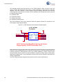
Figure 3-3. FTMF Expansion Card Expansion Header Signals
0.100" 8x2 Male
Pin Header
VEXP
ISSP_XRES
ISSP_CLK
ISSP_DAT
VEXP
J1
1
3
5
7
9
11
13
15
NC
VEXP_IN
VEXP_OUT
GND
ISSP_XRES SDA-MOSI
ISSP_CLK SCL-SCLK
GPIO5
ISSP_DAT
GPIO4
EXP_TYPE
MISO
GPIO3
GPIO2
SPI_nss
2
4
6
8
10
12
14
16
I2C_SDA
I2C_SCL
PO5
PO4
PO3
PO2
8X2 PIN HDR RA
NOTE: This Expansion Board Does Not Have An Onboard
Voltage Regulator - DO NOT Power With > 5Vdc
Notice that the 8x2 pin expansion header also includes four General Purpose IO connections labeled
P02-P05. These are hard wired to four unused Port 0 IO pins on the CY8C21434 host and allow you
to easily connect the FTMF Expansion Card to your specific hardware or sensors. These IO pins
were specifically chosen because they have the ability to operate as analog outputs, analog inputs,
digital inputs, digital outputs, or any combination of the four types; this pin selection makes them true
analog or digital GPIO.
Your PSoC Express project designates the specific function for these A/D GPIO pins.
20
CY3270 PSoC® FirstTouch™ Guide, Document # 001-15945 Rev. **
A
B
C
ZVREF
ALARM
5
10K 1%
R11
R6
1K
Ambient Light
Detector
560
0603
D
VEXP
1
1
TV1
SOT-23
LS1
CSS-J4D20
Q1
2N7002
R8
100
VEXP
R19
4.99K 1%
LSENSE
25
TV2
TV3
TV4
TV5
Temperature
Sensor
RT1
10K 1%
TSENSE
4
Proximity
PRX1
Sensor
R7
1 1
Loop
RECEPTACLE 1x1
10K .1%
R1
D4
2.4V 150mW
+ PR1
LX1972A
2
R20
1
2
VEXP
1
2
0603
0603
0603
1
2
0603
560
CSENSE1
CSENSE2
CSENSE3
CSENSE4
CSENSE5
CSENSE6
CSENSE7
PO2
PO3
PO4
PO5
LSENSE
ZVREF
TSENSE
0402
P2_0
P2_1
P2_2
P2_3
P2_4
P2_5
P2_6
P2_7
P0_0
P0_1
P0_2
P0_3
P0_4
P0_5
P0_6
P0_7
0402
TV6
VEXP
C2
0.1 uFd
VEXP
20
5
21
4
22
3
23
2
24
1
25
31
26
30
27
29
U3
VEXP
18
7
19
6
13
11
14
10
15
9
16
8
R5
ISSP_DAT
ISSP_CLK
LED_BLUE
LED_RED
LED_GRN
I2C_SDA
ALARM
I2C_SCL
TV7
C3
0.1 uFd
A
3
+ C4
4.7 uFd 16v
0603
2
680
2K
1K
G
B
5
6
0.01 uFd
C1
2.2K
R10
VEXP
VEXP
1
3
5
7
9
11
13
15
2
8X2 PIN HDR RA
NC
VEXP_IN
VEXP_OUT
GND
ISSP_XRES SDA-MOSI
ISSP_CLK SCL-SCLK
GPIO5
ISSP_DAT
GPIO4
EXP_TYPE
MISO
GPIO3
SPI_nss
GPIO2
J1
0.100" 8x2 Male
Pin Header
2
4
6
8
10
12
14
16
I2C_SDA
I2C_SCL
PO5
PO4
PO3
PO2
VEXP
R18
R17
CSENSE6
CSENSE7
R16
CSENSE5
R15
R14
CSENSE3
CSENSE4
R13
R12
CSENSE2
CSENSE1
2
Date:
Size
B
Title
CSB1
2
2
2
2
2
2
2
Cap Sense FTMF
CS GND
Cap Sense FTMF
CSB7
CS GND
Cap Sense FTMF
CSB6
CS GND
Cap Sense FTMF
CSB5
CS GND
Cap Sense FTMF
CSB4
CS GND
Cap Sense FTMF
CSB3
CS GND
Cap Sense FTMF
CSB2
CS GND
PCB:PDCR-9402
1
1
1
1
1
1
1
1
Monday, July 16, 2007
Document Number
REF-14209
1
Sheet
FIRST TOUCH MULTI FUNCTION BOARD
1
of
CYPRESS SEMICONDUCTOR © 2007
560
560
560
560
560
560
560
7-Element CS Slider
NOTE: This Expansion Board Does Not Have An Onboard
Voltage Regulator - DO NOT Power With > 5Vdc
ISSP_XRES
ISSP_CLK
ISSP_DAT
2.2K
R9
VEXP
3
4
R
LED BLUE GREEN RED
1
560
ISSP_XRES
CY8C21434 MLF32
P3_0
P3_1
P3_2
P3_3
P1_0
P1_1
P1_2
P1_3
P1_4
P1_5
P1_6
P1_7
XRES
17
LED_RED R4
LED_GRN R3
LED_BLUE R2
D1
RGB LED
Cluster
0603
3
0603
TV8
0603
0603
3
28
VCC
VSS
VSS
CP
12
32
CP
0603
4
0603
0603
0603
CY3270 PSoC® FirstTouch™ Guide, Document # 001-15945 Rev. **
2
0603
0603
0603
0603
0603
0603
0603
5
1
Rev
**
A
B
C
D
Technical Reference
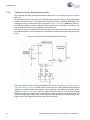
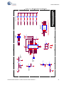
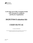
Figure 3-4. FTMF Expansion Card Schematic
21
Technical Reference
Since the FTMF Expansion Card connects the various sensors and output devices to predefined IO
of the host CY8C21434, it is important that you follow the pin assignment shown in Figure 3-4 on
page 21 and Table 3-1.
The schematic for the FTMF Expansion Card shown in Figure 3-4 is found on the CD included in the
kit.
Table 3-1. FTMF PSoC Pin Assignments
22
Pin Number
Port Number
Design Function
1
P0[1]
CapSense modulator capacitor
2
P2[7]
CapSense slider element 7
3
P2[5]
CapSense slider element 5
4
P2[3]
CapSense slider element 3
5
P2[1]
CapSense slider element 1
6
P3[3]
Unused / no-connect
7
P3[1]
CapSense feedback resistor
8
P1[7]
I2C clock line (SCL)
9
P1[5]
I2C data line (SDA)
10
P1[3]
Red LED drive
11
P1[1]
In system programming clock (ISSP_SCLK)
12
GND
13
P1[0]
In system programming data (ISSP_DAT)
14
P1[2]
Blue LED drive
15
P1[4]
Green LED drive
16
P1[6]
Alarm/buzzer FET drive
17
XRES
In system programming reset pin (ISSP_XRES)
18
P3[0]
Unused / no-connect
19
P3[2]
Unused / no-connect
20
P2[0]
CapSense proximity antenna pad (PRX1)
21
P2[2]
CapSense slider element 2
22
P2[4]
CapSense slider element 4
23
P2[6]
CapSense slider element 6
24
P0[0]
Thermistor temperature sensor analog input
25
P0[2]
User A/D-GPIO
26
P0[4]
User A/D-GPIO
27
P0[6]
Ambient light detector analog input
28
+Vdd
29
P0[7]
Thermistor drive-voltage reference analog input
30
P0[5]
User A/D-GPIO
31
P0[3]
User A/D-GPIO
32
GND
CY3270 PSoC® FirstTouch™ Guide, Document # 001-15945 Rev. **
Technical Reference
You can use the sensors and output devices in any way you want within your project, but you must
make sure to always assign the correct pins within your project. Failure to do so may cause unpredictable or unplanned project results.
Referring to Figure 3-4 on page 21, for instance, notice that a capacitor and a resistor connect to
Port P0[1] and P3[1]. These two components form the feedback network required for all CapSense.
When you assign the pinout in your PSoC Express CapSense projects, make certain to assign these
pins to the correct functions.
CY3270 PSoC® FirstTouch™ Guide, Document # 001-15945 Rev. **
23
Technical Reference
24
CY3270 PSoC® FirstTouch™ Guide, Document # 001-15945 Rev. **