1
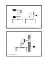
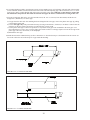
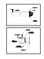
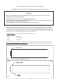
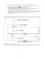
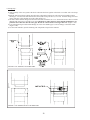
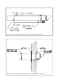
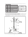
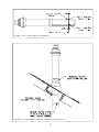
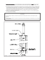
BWC070, BWC090, BWC120
Installation Manual Supplement
June 12th, 2007
The following pages are copied from the latest edition of the installation manual for
the above boilers, which is not yet in print. These pages cover new vent options that have
been added for these boilers and which are not shown in the current manual. These
options include:
1) 80/125mm concentric venting may be used to achieve longer vent runs.
2) 80/125mm concentric venting may be used for vertical vent applications.
3) An 80/125mm concentric snorkel kit is now offered.
4) Metal-Fab “Corr/Guard” may now be used for stainless steel vent applications.
Refer to the installation manual supplied with the boiler for important warnings and
other information not covered in this supplement.
VII Venting
WARNING
FAILURE TO VENT THIS BOILER IN ACCORDANCE WITH THESE INSTRUCTIONS COULD CAUSE
FLUE GAS TO ENTER THE BUILDING RESULTING IN SEVERE PROPERTY DAMAGE, PERSONAL
INJURY, OR DEATH:
* Do not attempt to vent this boiler with galvanized, PVC, or any other vent components not listed in Table 7.4.
* Do not attempt to mix components from different approved vent systems.
* Do not obtain combustion air from within the building.
* Do not install a barometric damper or drafthood on this boiler.
CAUTION
Moisture and ice may form on the surfaces around the vent termination. To prevent deterioration,
surfaces should be in good repair (sealed, painted, etc.).
A. Vent System Design
There are four basic ways to vent this boiler:
• Horizontal (“Side Wall”) Concentric Venting - Vent system exits the building through an outside wall.
Concentric venting consists of a “pipe within a pipe”. Flue gas exits the building through the inner pipe and
combustion air is drawn into the boiler through the space between the inner and outer pipe.
• Horizontal (“Side Wall”) Twin Pipe Venting - Vent system exits the building through an outside wall.
Combustion air and flue gas are routed between the boiler and outdoors using separate pipes.
• Vertical Concentric Venting - Vent system exits the building through the roof. Concentric venting consists of a
“pipe within a pipe”. Flue gas exits the building through the inner pipe and combustion air is drawn into the boiler
through the space between the inner and outer pipe.
• Vertical Twin Pipe Venting - Vent system exits the building through a roof. Combustion air and flue gas are
routed between the boiler and outdoors using separate pipes.
All of these systems are considered “direct vent” because in all of them air for combustion is drawn directly from
the outdoors into the boiler. A description of all of these venting options are shown in Tables 7.1 and 7.9. For clarity,
these vent options are numbered from 1 to 6. One of the vent option columns in Tables 7.1 or 7.9 must match the
planned vent and air intake system exactly. In addition, observe the following guidelines:
1) Approved vent systems - Use only one of the approved vent systems shown in Tables 7.4 or 7.5. These vent systems
fall into two basic categories:
• Concentric Vent System - The standard boiler is supplied with a concentric vent system having a maximum
usable length of 25” (Figure 1.1). For longer runs, additional straight lengths and elbows are available from
Crown. In some cases, larger diameter concentric pipe must be used. Each Crown concentric vent component
consists of an inner pipe of polypropylene and the outer pipe of steel. Integral gaskets on each concentric fitting
provide a gas tight seal. A list of all Crown concentric vent components is shown in Table 7.4.
In this manual, concentric pipe sizes are called out in terms of the inner and outer pipe nominal diameters in
millimeters. For example, “60/100mm” pipe consists of a 60mm exhaust pipe inside a 100mm diameter outer pipe.
• Twin Pipe Vent Systems - Approved vent systems are made of a special stainless steel alloy (AL29-4C) for
protection against corrosive flue gas condensate. They are designed to provide a gas tight seal at all joints and
seams so that flue gas does not enter the building. Each approved vent system has a unique method for installation
- do not attempt to mix components from different vent systems. A list of approved twin pipe vent systems is
shown in Table 7.5. Note that a special vent collar (Crown PN 230510) is required if the boiler is to be vented
with one of the approved stainless vent systems.
11
2) Maximum Vent and Air Intake Lengths - The maximum length of the vent air intake piping depends upon the vent
option selected and the boiler size. See Table 7.1 or 7.9 for the maximum vent length. In horizontal vent systems,
the lengths shown in Table 7.1 are in addition to the first standard elbow on top of the boiler. For vertical vent
systems, the maximum vertical vent lengths shown in Table 7.9 are in addition to two standard radius elbows. If more
elbows are desired, the maximum allowable vent length must be reduced by the amount shown in Table 7.8 for each
additional elbow used. Termination fittings are never counted, although the length of the concentric terminal section
is counted.
Example:
A 60/100mm concentric vent system is planned for a horizontally vented BWC120 which has the following
components:
80/125 x 60/100mm Reducing Elbow (supplied with the boiler)
5ft Straight Pipe
90 elbow
1-1/2ft Straight Pipe
45Elbow
Uncut Terminal Section (supplied with the boiler)
The Vent Option #1 column in Table 7.1 describes a horizontal direct vent system using 60/100mm concentric vent
pipe. From this column, we see that a BWC120 may have a vent length of up to 18ft. The 90 degree reducing elbow
is not considered. The length of the terminal section (not including the plastic terminal itself) is approximately 22
1/2” (1.9ft) installed. From Table 7.8, we see that the equivalent length of the 60/100mm elbow is 4.5ft and that the
equivalent length of the 45 degree elbow is 4ft. The total equivalent length of the planned venting system is therefore:
5ft (Straight ) + 4.5ft (90 Elbow) + 1.5ft (Straight ) + 4 ft (45 Elbow) + 1.9ft (Uncut Terminal Section) = 16.9ft.
Since Table 7.1 shows a maximum allowable vent length of 18ft, the planned vent system length is acceptable.
3) Minimum Vent and Air Intake Lengths - Observe the minimum vent lengths shown in tables 7.1 and 7.9.
4)
Permitted Terminals for Horizontal Venting:
• Vent Option 1 - The 60/100mm concentric vent terminal is supplied with the boiler as part of the standard vent
system.
• Vent Option 2 - The exhaust terminal is Crown PN 230511. The air intake fitting is a 90 degree elbow with a rodent
screen supplied by the installer. This elbow is made out of the same material as the rest of the air inlet system
(either galvanized or PVC) and is installed as shown in Figure 7.3.
• Vent Option 3 - Two terminals are permitted:
a) 80/125mm Concentric Vent Terminal (Crown PN 230531)
b) 80/125mm Snorkel Terminal (Crown PN 230540) . This terminal allows the vent system to exit the building
close to grade and go up the exterior wall far enough to provide adequate clearance between the terminal itself
and the snow line (Figure 7.7).
5)
Horizontal Vent and Air Intake Terminal Location - Observe the following limitations on the vent terminal location
(also see Figures 7.6, 7.7). When locating a concentric terminal, observe the limitations outlined below for “vent
terminals”.
• Vent terminals must be at least 1 foot from any door, window, or gravity inlet into the building.
• For twin pipe terminals, maintain the correct clearance and orientation between the vent and air intake terminals.
The vent and air intake terminals must be at the same height and their center lines must be between 12 and 36
inches apart. Both terminals must be located on the same wall.
• The bottom of all terminals must be at least 12” above the normal snow line. In no case should they be less than
12” above grade level.
• The bottom of the vent terminal must be at least 7 feet above a public walkway.
• Do not install the vent terminal directly over windows or doors.
• The bottom of the vent terminal must be at least 3 feet above any forced air inlet located within 10 feet.
• A clearance of at least 4 feet horizontally must be maintained between the vent terminal and gas meters, electric
meters, regulators, and relief equipment. Do not install vent terminal over this equipment.
• Do not locate the vent terminal under decks or similar structures.
• Top of vent terminal must be at least 5 feet below eves, soffits, or overhangs. Maximum depth of overhang is 3 ft.
12
Horizontal Terminal Clearance Requirements (continued):
• Vent terminal must be at least 6 feet from an inside corner.
• Under certain conditions, water in the flue gas may condense, and possibly freeze, on objects around the vent
terminal including on the structure itself. If these objects are subject to damage by flue gas condensate, they
should be moved or protected.
• If possible, install the vent and air intake terminals on a wall away from the prevailing wind. Reliable operation
of this boiler cannot be guaranteed if these terminals are subjected to winds in excess of 40 mph.
• Air intake terminal must not terminate in areas that might contain combustion air contaminates, such as near
swimming pools. See Section IV for more information on possible contaminates.
TABLE 7.1: SUMMARY OF HORIZONTAL VENTING OPTIONS
VENT OPTION #
1
CLASSIFICATION USED IN THIS
MANUAL
2
HORIZONTAL
CONCENTRIC
HORIZONTAL
TWIN PIPE
3
HORIZONTAL
CONCENTRIC
ILLUSTRATED IN FIGURE
7.2
7.3
7.2
VENT PIPE PENETRATION
THROUGH STRUCTURE
WALL
WALL
WALL
AIR INTAKE PIPE PENETRATION
THROUGH STRUCTURE
WALL
WALL
WALL
60/100 mm
CONCENTRIC
3”
3”
80/125 mm
CONCENTRIC
BWC070
32ft
55ft
55ft
BWC090
32ft
55ft
55ft
BWC120
18ft
55ft
55ft
BWC070
32ft
55ft
55ft
BWC090
32ft
55ft
55ft
BWC120
18ft
55ft
55ft
BWC070
10in
2ft
2ft
BWC090
10in
2ft
2ft
BWC120
10in
2ft
2ft
BWC070
10in
2ft
2ft
BWC090
10in
2ft
2ft
BWC120
10in
2ft
2ft
VENT PIPE SIZE
VENT
INLET
VENT
INLET
MINIMUM LENGTH
MAXIMUM LENGTH
AIR INTAKE PIPE SIZE
VENT TERMINAL
AIR INTAKE TERMINAL
VENT MATERIAL
AIR INTAKE MATERIAL
60/100 mm
CONCENTRIC
CROWN
60/100mm
VENT
COMPONENTS
SHOWN IN
TABLE 7.4a
(Note #1)
CROWN
#230511
3” 90 ELBOW
Crown 230531
CONCENTRIC
or 230540
SNORKEL
APPROVED
STAINLESS
STEEL VENT
SYSTEM
SHOWN IN
TABLE 7.5
CROWN
80/125mm VENT
COMPONENTS
SHOWN IN
TABLE 7.4b
GALVANIZED
OR PVC
Note #1: In Vent Option #1, the 80/125mm concentric straight section (PN 230515) shown in Table 7.4a may be used between the
boiler and the first 80/125 x 60/100 reducing elbow. If this is done, the overall maximum vent length is still restricted to that shown for
Vent Option #1 in Table 7.1 above.
13
FIGURE 7.2: HORIZONTAL CONCENTRIC VENTING
(VENT OPTION 1,3)
FIGURE 7.3: HORIZONTAL TWIN PIPE VENTING (VENT OPTION 2)
14
TABLE 7.4a: CROWN CONCENTRIC 60/100 VENT COMPONENTS
(VENT OPTION 1)
CROWN PN
DESCRIPTION
SIZE
USED ON
VENT
OPTION #
COMMENTS
230521
80/125 x 60/100mm REDUCING
ELBOW
80/125 x
60/100mm
1
INCLUDED WITH STANDARD BOILER
230520
TERMINAL SECTION
60/100mm
1
INCLUDED WITH STANDARD BOILER
230522
WALL GROMMET
60/100mm
1
INCLUDED WITH STANDARD BOILER
230505
39” STRAIGHT
60/100mm
1
OPTIONAL - MAY NOT BE CUT
230504
78” STRAIGHT
60/100mm
1
OPTIONAL - MAY NOT BE CUT
230506
19 1/2” STRAIGHT
60/100mm
1
OPTIONAL - CAN BE CUT
230507
90 DEGREE ELBOW
60/100mm
1
OPTIONAL
230508
45 DEGREE ELBOW
60/100mm
1
OPTIONAL
230515
39” STRAIGHT
80/125mm
1
OPTIONAL - CAN BE CUT (Note #1)
Note #1: On 60/100mm vent systems, this may only be used between the boiler and the first 80/125 x 60/100 Reducing elbow (see text).
TABLE 7.4b: CROWN CONCENTRIC 80/125 VENT COMPONENTS
(VENT OPTIONS 3,6)
CROWN PN
DESCRIPTION
SIZE
USED ON
VENT
OPTION #
230527
90 DEGREE EL (STANDARD)
80/125mm
3,6
230528
90 DEGREE EL (SWEEP)
80/125mm
3,6
230526
45 DEGREE EL
80/125mm
3,6
230517
19 1/2” STRAIGHT
80/125mm
3,6
CAN BE CUT
230515
39” STRAIGHT
80/125mm
3,6
CAN BE CUT
230518
39” STRAIGHT
80/125mm
3,6
MAY NOT BE CUT
230519
78” STRAIGHT
80/125mm
3,6
MAY NOT BE CUT
230525
TELESCOPING STRAIGHT
80/125mm
3,6
ADJUSTABLE FROM 12-1/2” TO 16-1/2
230531
HORIZONTAL TERMINAL
80/125mm
3
230540
SNORKEL KIT
80/125mm
3
(NOTE #1)
230532
VERTICAL TERMINAL
80/125mm
6
(NOTE #2)
230533
FLAT ROOF FLASHING
80/125mm
6
230535
SLOPED ROOF FLASHING
80/125mm
6
(NOTE #3)
230530
SUPPORT ELBOW WITH
CHIMNEY CHASE BRACKET
80/125mm
6
(NOTE #4)
230536
SUPPORT BAND
80/125mm
3,6
Table 7.4b Notes:
1) Snorkel kit includes parts needed to offset terminal on exterior wall by up to 46”.
2) Vertical terminal can be used with either of the roof flashings listed beneath it.
3) Sloped roof flashing suitable for roof angles between 25 and 45 degrees.
4) Used at base of vertical run inside unused masonry chimney.
15
COMMENTS
6)
Permitted Terminals for Vertical Venting • Vent Option 5 - A straight termination is installed in the end of the vent pipe. Vent manufacturer part numbers for these
screens are shown in Table 7.5. The air inlet terminal consists of a 180 degree elbow (or two 90 degree elbows) with a
rodent screen as shown in Figure 7.10.
• Vent Option 6 - Use Crown PN 230532 with the appropriate flashing (Table 7.4b)
7) Vertical Vent Terminal Locations (Vent Options 5,6) - Observe the following limitations on the location of all vertical vent
terminals (see Figures 7.10, 7.11):
• The top of the vent pipe must be at least 2 feet above any object located within 10 feet.
• For Vent Option #5, the vertical distance between top of the vent and air inlet terminal openings must be at least 12”.
• The bottom of the air inlet terminal must be at least 12” above the normal snow accumulation that can be expected on
the roof. The terminal used in Vent Option #6 has a fixed distance above the storm collar of 19”. If a greater distance is
needed to provide the clearance above the snow line, build a chase on the roof and mount the vertical terminal on top of
the chase.
• For Vent Option #5, the air intake terminal must be located on the roof and must be no further than 24” horizontally from
the exhaust pipe.
8) Wall thimbles – Wall thimbles are required where single wall vent pipe passes through combustible walls with less than
the required clearance shown in Table 4.2 or as required by local codes. Stainless vent manufacturer’s wall thimble part
numbers are shown in Table 7.5. Note that concentric vent has a “zero” clearance to combustibles and therefore does not
require the use of wall thimbles.
TABLE 7.5: PERMISSIBLE STAINLESS STEEL VENT SYSTEMS
AND PRINCIPLE VENT COMPONENTS
(VENT OPTIONS 2, 5)
MANUFACTURER
VENT
SYSTEM
HEAT FAB
SAF-T
VENT
EZ SEAL
PROTECH
SYSTEMS
INC.
Z-FLEX
METAL-FAB
FASNSEAL
SVE
SERIES III
(“Z-VENT
III”)
CORR/
GUARD
SIZE
COMPONENT
PART NUMBER
3
BOILER COLLAR
CROWN 230510
3
WALL THIMBLE
HEAT FAB 7393, 7393GCS, 5391CI
3
HORIZONTAL TERMINAL
CROWN 230511
3
VERTICAL TERMINAL
HEAT FAB 9392
3
BOILER COLLAR
CROWN 230510
3
WALL THIMBLE
FSWT3
3
HORIZONTAL TERMINAL
3
VERTICAL TERMINAL
3
BOILER COLLAR
3
WALL THIMBLE
3
HORIZONTAL TERMINAL
3
VERTICAL TERMINAL
3
BOILER COLLAR
CROWN 230510
3
WALL THIMBLE
CGSWWPK(3”)
3
HORIZONTAL TERMINAL
CROWN 230511
3
VERTICAL TERMINAL
CGSWHTM(3”)
CROWN 230511
FSBS3
CROWN 230510
2SVSWTEF03
CROWN 230511
24SVSTPF03
NOTES:
1) See vent system manufacturer’s literature for other part numbers that are required such as straight pipe, elbows, firestops and vent supports.
2) Crown 230510 collar replaces factory-mounted concentric collar (Figure 7.16).
16
FIGURE 7.6a: LOCATION OF VENT TERMINAL RELATIVE TO WINDOWS, DOORS, GRADE
FIGURE 7.6b: LOCATION OF VENT TERMINAL RELATIVE TO METERS AND FORCED AIR INLETS
FIGURE 7.6c: POSITIONING VENT TERMINAL UNDER OVERHANGS
17
9) Pitch of Horizontal Piping - Pitch all horizontal piping so that any condensate which forms in the piping will run
towards the boiler:
• Pitch Crown horizontal concentric venting 5/8” per foot
• Pitch Stainless steel venting 1/4” per foot.
10) Supporting Pipe - Vertical and horizontal sections of pipe must be properly supported:
• Support Crown concentric venting near the female end of each straight section of pipe.
Exception: Vertical runs of concentric pipe in an unused chinmey (Figure 7.36) need only be supported at the
terminal and at the base of the run.
• Support stainless steel venting as called for by the vent manufacturer’s instructions.
FIGURE 7.7: SNORKEL TERMINAL CONFIGURATION
18
TABLE 7.8: VENT/ AIR INTAKE FITTING EQUIVALENT LENGTH
VENT FITTING
EQUIVALENT LENGTH (ft)
60/100mm 90° CONCENTRIC ELBOW
4.5
60/100mm 45° CONCENTRIC ELBOW
4.0
80/125mm 90° CONCENTRIC ELBOW
8.5
80/125mm 90° SWEEP CONCENTRIC ELBOW
5.5
80/125mm 45° CONCENTRIC ELBOW
3.0
80/125mm 90° CONCENTRIC SUPPORT ELBOW
8.5
3” SINGLE WALL 90° ELBOW
5.5
3” SINGLE WALL 45° ELBOW
4.0
TABLE 7.9: SUMMARY OF VERTICAL VENTING OPTIONS
VENT OPTION #
5
VERTICAL
TWIN PIPE
CLASSIFICATION USED IN THIS
MANUAL
6
VERTICAL
CONCENTRIC
ILLUSTRATED IN FIGURE
7.10
7.11
VENT PIPE PENETRATION
THROUGH STRUCTURE
ROOF
ROOF
AIR INTAKE PIPE STRUCTURE
THROUGH STRUCTURE
ROOF
ROOF
3”
INLET
VENT
INLET
MINIMUM LENGTH
VENT
3”
AIR INTAKE PIPE SIZE
MAXIMUM LENGTH
VENT PIPE SIZE
80/125 mm CONCENTRIC
BWC070
49.5ft
49.5ft
BWC090
49.5ft
49.5ft
BWC120
49.5ft
49.5ft
BWC070
49.5ft
49.5ft
BWC090
49.5ft
49.5ft
BWC120
49.5ft
49.5ft
BWC070
2ft
2ft
BWC090
2ft
2ft
BWC120
2ft
2ft
BWC070
2ft
2ft
BWC090
2ft
2ft
2ft
2ft
BWC120
VENT TERMINAL
STRAIGHT TERMINAL
BY VENT SYSTEM MFR.
(TABLE 7.5)
3” 180° ELBOW
(FIGURE 7.10)
AIR INTAKE TERMINAL
VENT MATERIAL
AIR INTAKE MATERIAL
APPROVED STAINLESS
STEEL VENT SYSTEM
GALVANIZED OR PVC
19
CROWN #230532
CONCENTRIC TERMINAL
(TABLE 7.4b)
CROWN 80/125 mm VENT
COMPONENTS SHOWN IN
TABLE 7.4b
FIGURE 7.10: VERTICAL TWIN PIPE VENT SYSTEM (VENT OPTION 5)
FIGURE 7.11: VERTICAL CONCENTRIC VENT SYSTEM (VENT OPTION 6)
20
B. Removing an Existing Boiler From a Common Chimney
Read this only if the BWC boiler is replacing an existing boiler that is being removed from a common chimney. This
section does not apply to the installation of a BWC boiler.
In some cases, when an existing boiler is removed from a common chimney, the common venting system may be too
large for the remaining appliances. At the time of removal of an existing boiler, the following steps shall be followed
with each appliance remaining connected to the common venting system placed in operation, while the other appliances
remaining connected to the common venting system are not in operation.
(a) Seal any unused openings in the common venting system.
(b) Visually inspect the venting system for proper size and horizontal pitch and determine there is no blockage or
restriction, leakage, corrosion and other deficiencies which could cause an unsafe condition.
(c) Insofar as practical, close all building doors and windows and all doors between the space in which all the
appliances remaining connected to the common venting system are located and other spaces of the building.
Turn on clothes dryers and any appliance not connected to the common venting system. Turn on any exhaust
fans, such as range hoods and bathroom exhausts, so they will operate at maximum speed. Do not operate a
summer exhaust fan. Close fireplace dampers.
(d) Place in operation the appliance being inspected. Follow the lighting instructions. Adjust thermostat so the
appliance will operate continuously.
(e) Test for spillage at the draft hood relief opening after 5 minutes of main burner operation. Use the flame of a
match or candle, or smoke from a cigarette, cigar, or pipe.
(f) After it has been determined that each appliance remaining connected to the common venting system properly
vents when tested as outlined above, return doors, windows, exhaust fans, fireplace dampers and any other
gas-burning appliances to their previous condition of use.
(g) Any improper operation of the common venting system should be corrected so the installation conforms with
the National Fuel Gas Code, ANSI Z223.1. When re-sizing any portion of the common venting system, the
common venting system should be re sized to approach the minimum size as determined using the appropriate
tables in Part 11 of the National Fuel Gas Code, ANSI Z223.1.
WARNING
NEVER COMMON VENT A BWC BOILER WITH OTHER APPLIANCES.
21
C. Assembly of Crown 60/100mm Concentric Venting
(IMPORTANT - Skip to Section D for 80/125mm Concentric Vent Assembly)
WARNING
Failure to follow the instructions could result in flue gas leakage into the combustion air or indoor air,
resulting in unsafe or unreliable operation.
• Do not lubricate concentric gaskets with anything other than water.
• Do not attempt to cut any piping except as permitted in this section. When cutting these sections, make sure
all cuts are square and allow for proper insertion.
• Do not attempt to try to mix this concentric pipe with other venting systems.
1) Concentric vent components supplied with the boiler are packed inside the boiler carton and include the following:
a) 80/125 x 60/100mm reducing elbow (Crown PN 230521).
b) 60/100mm terminal section (straight section with a terminal and overall length of 27 3/4” (Crown PN 230520).
c) Two (2) Rubber wall grommets (Crown PN 230522).
2) Unless the 80/125 straight riser (PN 230515) is used, start by attaching the reducing elbow to the boiler collar. To
do so, remove the clamp from the large end of the reducing elbow and set aside. Apply a small amount of water to
the brown gasket on the boiler collar. Push the elbow onto the boiler collar until the bead on the elbow contacts the
top edge of the collar (Figure 7.20).
3) Reinstall the clamp removed in Step (2) so that the elbow is secured to the boiler collar.
4) If no additional sections of concentric pipe are required, attach the terminal section to the elbow. In most cases, it
will need to be cut before doing so. Use the following procedure to cut the pipe:
a) Measure distance “L” from the outside surface of the exterior wall to the end of the elbow as shown in Figure
7.21.
b) Add 2-1/8” to distance “L”. Carefully mark this length on the pipe as shown in Figure 7.22.
c) Press in the two tabs holding the plastic terminal in the terminal section (Figure 7.22). Carefully pull out the
terminal and the inner pipe.
d) Cut the outer pipe only at the point marked in Step (b) using aviation shears, a hacksaw, or an abrasive wheel
cutter. Be careful to cut the pipe square. De burr the cut end with a file or emery cloth.
e) Cut the plastic inner pipe so that it will protrude 3/8” beyond the outer pipe when reinstalled in the terminal
section (Figure 7.23). Use a fine tooth hacksaw or a PVC saw to cut the plastic pipe and be careful to cut the pipe
square. De burr the cut edge of the plastic pipe with a file, razor blade, or fine sandpaper.
f) Reinstall the inner pipe in the terminal section. Slip the outside wall grommet over the terminal section and
position so that it covers the joint between the outer pipe and the terminal (Figure 7.24).
g) Make a mark on the terminal section 1” from the cut end of the outer pipe as shown in Figure 7.24.
h) Pass the terminal section through the wall from the outside. Push the remaining wall grommet over the terminal
section on the inside of the wall. Push the terminal section into the elbow until the mark made in Step (g) is no
longer visible. If necessary, the brown gasket in the inner pipe may be lubricated with a few drops of water.
i) The terminal section must be attached to the elbow with a single #10 x 1/2” sheet metal screw ( not supplied) at
the top of the elbow. Drill a 1/8” hole in the location shown in Figure 7.25. Use a short drill bit or a drill stop
to ensure that the drill bit does not penetrate the pipe by more than 3/8”. Install a #10 x 1/2” screw in this
hole. Do not use a screw longer than 1/2” long.
j) If not already done, make sure that both wall grommets are firmly against the interior and exterior wall surfaces.
Seal any cracks or other openings near the terminal through which exhaust could enter the building.
5) If additional pieces of pipe are used, install them starting at the boiler elbow. Support each section of straight pipe
at its female end.
22
FIGURE 7.20: INSTALLATION OF REDUCING ELBOW ON CONCENTRIC BOILER COLLAR
FIGURE 7.21: DIMENSION “L”
23
6) Use locking bands provided to join adjacent sections of non-cuttable pipe as well as fittings. The male end of the terminal
section and other cuttable sections must be held to the female end of the adjoining pipe with at least three #10 x 1/2” sheet
metal screws. Drill a 1/8 hole through both outer pipes to start this screw. Use a drill stop or other means to ensure that
the drill bit does not penetrate more than 3/8” into the outer pipe. Do not use a sheet metal screw longer than 1/2”.
7) The only straight pipe that can be cut is the terminal section, the 19-1/2” section (Crown PN 230506) and the 80/125
straight riser (PN230515). To cut this pipe:
a) Cut pipe from the male end. After marking the desired length of the outer pipe, remove the plastic inner pipe by pulling
it out from the female end.
b) Cut the outer pipe only at the point marked in Step (b) using aviation shears, a hacksaw, or an abrasive wheel cutter. Be
careful to cut the pipe square. De burr the cut end with a file or emery cloth.
c) Cut the plastic inner pipe so that it will protrude 3/8” beyond the outer pipe when reinstalled in the outer pipe. Use a
fine tooth hacksaw or a PVC saw to cut the plastic pipe and be careful to cut the pipe square. De burr the cut edge of the
plastic pipe with a file, razor blade, or fine sandpaper.
d) Reinstall the inner pipe.
8) Install the terminal as outlined in Step (4) above. Dimension “L” described in Step 4 is the distance from the exterior surface of the wall to the end of the last piece of pipe inside the building.
FIGURE 7.22: CUTTING OUTER PIPE
FIGURE 7.23: CUTTING INNER PIPE
24
FIGURE 7.24: PREPARING 60/100mm TERMINAL SECTION FOR INSTALLATION IN THE WALL
FIGURE 7.25: ATTACHING 60/100mm TERMINAL SECTION
25
D. Assembly of Crown 80/125mm Concentric Venting
(IMPORTANT - See Section C for 60/100mm Concentric Vent Assembly)
WARNING
Failure to follow the instructions could result in flue gas leakage into the combustion air or indoor air,
resulting in unsafe or unreliable operation.
• Do not lubricate concentric gaskets with anything other than water.
• Do not attempt to cut any piping except as permitted in this section. When cutting these sections, make sure
all cuts are square and allow for proper insertion.
• Do not attempt to try to mix this concentric pipe with other venting systems.
1) The 60/100mm terminal section and concentric reducing elbow supplied with the boiler are not used in 80/125mm
vent systems. The components listed in Table 7.4b are required for 80/125mm installations and are not supplied
with the boiler. Before starting assembly of an 80/125mm vent system, make sure that the planned installation is in
accordance with the “Vent System Design” section of this manual and that all required 80/125mm vent components
are on hand. These components are available through Crown distributors.
2) Cutting Straight Pipe - The following straight pipe sections may be cut:
Part #
230517
230515
Description
19 1/2” Straight
39” Straight
These sections have a plain male end (without beads - see Figure 7.30a). They are always cut from the male end.
Sections not shown on the above list may not be cut. These sections have beads on the male end (Figure 7.30b).
FIGURE 7.30a: CUTTABLE STRAIGHT SECTION
FIGURE 7.30b: NON CUTTABLE STRAIGHT SECTION
26
To cut the straight sections listed above refer to Figure 7.31 and the following instructions:
a) Determine the required length of the outer pipe. When doing this allow an additional 1” of length for insertion
into the female end of the adjoining pipe. Mark the cut line on the outer pipe.
b) Remove the plastic inner pipe by pulling it out from the female end.
c) Cut the OUTER PIPE ONLY at the point marked in Step (a) using aviation shears, a hacksaw, or an abrasive
wheel cutter. Be careful to cut the pipe square. De burr the cut end with a file or emery cloth.
d) Make an insertion mark 1” from the male end of the outer pipe.
e) Cut the plastic inner pipe so that it will protrude 3/8” beyond the male end of the outer pipe when reinstalled
in the outer pipe. Use a fine tooth hacksaw or a PVC saw to cut the plastic pipe and be careful to cut the pipe
square. De burr the cut edge of the plastic pipe with a file, razor blade, or fine sandpaper.
f) Reinstall the inner pipe.
FIGURE 7.31: CUTTING STRAIGHT PIPE
27
3) Joining Pipe a) Start assembly of the vent system at the boiler. Lubricate the brown gasket in the boiler vent collar with a few drops
of water.
b) Push the male end of the first fitting into the boiler collar until it bottoms out. The male end of cuttable sections
should go 1” into the collar until the insertion mark (made in Step 2d above) is covered. On other fittings, the bead
on the male pipe will be bottom out on the collar (Figure 32).
c) The male end of cuttable fittings must be held to the collar with three #10 x 1/2” sheet metal screws. Drill a 1/8 hole
through both outer pipes to start this screw. Use a drill stop or other means to ensure that the drill bit does not
penetrate more than 3/8” into the outer pipe. Do not use a sheet metal screw longer than 1/2” (Figure 7.32a).
d) Use locking bands (provided with all fittings) to secure non-cuttable pipe, as well as fittings, to the boiler collar
(Figure 7.32b).
e) Use the same method to join all remaining vent components except for the terminal.
FIGURE 7.32a: JOINING CUTTABLE PIPE
FIGURE 7.32b: JOINING NON CUTTABLE PIPE
28
4) 80/125mm Horizontal Terminal Installation a) Cut a 5-1/2” diameter hole through the exterior wall at the planned location of the horizontal terminal.
b) Measure distance “L” from the outside surface of the exterior wall to the end of the last fitting as shown in
Figure 7.33a.
c) Add 1-1/4” to distance “L”. Carefully mark this length on the pipe as shown in Figure 7.33b.
d) Remove the plastic inner pipe from the terminal, by gently pulling on it from the male end. Set aside.
e) Cut the outer pipe only at the point marked in Step (c) using aviation shears, a hacksaw, or an abrasive
wheel cutter. Be careful to cut the pipe square. De-burr the cut end with a file or emory cloth.
f) Reinstall the plastic inner pipe in the terminal, making sure that the female end of this pipe is completely
bottomed out over the aluminum male connection visible behind the air intake grill. Place a mark on the
plastic inner pipe 3/8” beyond the end of the outer pipe (Figure 7.33c). Use a fine tooth hacksaw or a
PVC saw to cut the plastic pipe and be careful to cut the pipe square (if necessary, the plastic pipe can be
removed from the terminal again for cutting). De-burr the cut edge of the plastic pipe with a file, razor
blade, or fine sandpaper.
g) Make a mark on the terminal section 1” from the cut end of the outer pipe as shown in Figure 7.33c.
h) Slip the terminal section through the wall from the outside. Pass the terminal through the inner wall plate
and push into the last section of vent pipe until the mark made in Step (h) is not longer visible (Figure
7.33d). Secure the terminal to the last piece of pipe with three #10 x 1/2” sheet metal screws. Drill a 1/8
hole through both outer pipes to start these screws. Use a drill stop or other means to ensure that the
drill bit does not penetrate more than 3/8” into the outer pipe. Do not use a sheet metal screw longer
than 1/2”.
i) Slip the outer wall plate over the terminal and secure to the wall (Figure 7.33d). Apply a 1/8” bead of
weather resistant RTV over the joint between the outside wall plate and the terminal. Secure the other wall
plate to the inside wall.
FIGURE 7.33a: DIMENSION “L”, 80/125mm HORIZONTAL TERMINAL
FIGURE 7.33b: CUTTING OUTER PIPE OF 80/125mm HORIZONTAL TERMINAL
29
FIGURE 7.33c: CUTTING INNER PIPE OF 80/125mm HORIZONTAL TERMINAL
FIGURE 7.33d: COMPLETING 80/125mm HORIZONTAL TERMINAL INSTALLATION
30
5) Snorkel Terminal Installation - The Snorkel Kit (PN 230540) consists of the following (Also see Figure 7.34):
Key #
1
2
Part #
230541
230542
Description
Support Elbow
Lower Wall Bracket
3
4
5
6
7
8
230543
230544
230545
230546
230527
230547
Air Intake Section
Wall Bracket
Terminal Elbow
Exhaust Terminal
Standard Elbow
Wall Penetration Section
*
230548
Outer Joint Gasket (2 provided)
IMPORTANT
The Terminal Elbow and Wall
Penetration Section included in the
snorkel kit have gaskets in the female
end of the outer pipe. These gaskets
prevent infitration of rain water
into the air intake section. Do not
interchange with similar components
shown in Table 7.4b.
a) Cut a 6” diameter hole through the exterior wall at the planned exit point of the vent. A minimum of 4” is needed
between the center line of this hole and grade to install the lower wall bracket.
b) Before mounting the lower wall bracket, loosen the M10 x 35 screw on this bracket. Adjust this bolt forward or
backward so that its center is 6-7/16” from the wall (Figure 7.34) and tighten.
c) Center the Lower Wall Bracket on the hole in the wall and mark the location of the four mounting screws on the
wall. 5/16” mounting screws (not supplied) are recommended for mounting this bracket. Drill mounting holes
and mount the bracket.
FIGURE 7.34: INSTALLATION OF SNORKEL TERMINAL
31
d) Complete the vent system inside the structure. The support elbow sits on the M10 x 35 screw as shown in Figure
7.34. Cut the Wall Penetration Section to the length required to connect the interior vent system to the Support Elbow
following the instructions on Page 26.
e) Remove the Support Elbow from the Lower Support Bracket and attach it to the Wall Penetration Section. Slip this
assembly through the Lower Support Bracket. Connect to the interior vent system.
f) Slide an Outer Joint Gasket over the male end of the Air Intake Section with the tapered edge of the gasket pointing
up. Attach the Air Intake Section to the Support Elbow. If necessary, the Air Intake Section can be shortened by
cutting the male end as described on page 26. After attaching the Air Intake Section to the Support Elbow, slide the
Outer Joint Gasket down over the joint between the two fittings to prevent rain infiltration.
g) Attach the Wall bracket to the wall 0”-6” from the bottom edge of the intake bell (Figure 7.34). Use 1/4” screws (not
provided) to mount this bracket.
h) Slide the remaining Outer Joint Gasket over the male end of the Terminal Elbow. Attach the Terminal Elbow to the Air
Intake Section, pointing it away from the wall. Secure the Terminal Elbow to the Air Intake section with a single #10
x 1/2” sheet metal screw (Figure 7.34). Drill a 1/8 hole through both outer pipes to start this screw. Use a drill stop
or other means to ensure that the drill bit does not penetrate more than 3/8” into the outer pipe. Do not use a
sheet metal screw longer than 1/2”. Slide the Outer Joint Gasket down over the joint between the Terminal Elbow
and the Air Intake Section to prevent rain infiltration.
i) Attach the Exhaust Terminal to the Terminal Elbow (Figure 7.34).
6) Vertical Terminal Installation - In addition to the vertical terminal, either a Flat Roof Flashing (PN 230533) or Sloped
Roof Flashing (PN 230535) is required for this installation.
a) Determine the center line of the terminal location on the roof. If the roof is flat, cut a 5-1/2” diameter hole for the
terminal. If the roof is sloped, cut a hole large enough for the terminal to pass through the roof while remaining
plumb. Caution: If the boiler is installed directly under the hole, cover it while cutting the hole to prevent saw
dust and other debris from falling into the boiler.
b) Install the roof flashing using standard practice for the roofing system on the structure.
c) If not already done, assemble the venting system inside the building. The last section of pipe needs to be on the same
center line as the terminal and within 19-1/4” of the top edge of the roof flashing (Figure 7.35a).
d) Measure distance “H” from the top edge of the storm collar to the end of the last fitting as shown in Figure 7.35a.
e) Add 1” to distance “H”. Carefully mark this length on the pipe as shown in Figure 7.35b.
f) Cut the outer pipe only at the point marked in Step (e) using aviation shears, a hacksaw, or an abrasive wheel cutter.
Be careful to cut the pipe square. De-burr the cut end with a file or emery cloth.
g) Place a mark on the aluminum inner pipe 3/8” beyond the end of the outer pipe (Figure 7.35b). Use a fine tooth
hacksaw to cut the aluminum pipe and be careful to cut the pipe square. De-burr the cut edge of the aluminum pipe
with a file or emery cloth.
h) Make a mark on the terminal section 1” from the cut end of the outer pipe as shown in Figure 7.35b.
i) Slip the terminal section through the roof from the outside. Push into the last section of vent pipe until the mark
made in Step (h) is not longer visible. Secure the terminal to the last piece of pipe with three #10 x 1/2” sheet metal
screws. Drill a 1/8” hole through both outer pipes to start these screws. Use a drill stop or other means to ensure
that the drill bit does not penetrate more than 3/8” into the outer pipe. Do not use a sheet metal screw longer
than 1/2”.
j) Secure the terminal section to the inside of the roof structure using the mounting bracket provided with the terminal
(Figure 7.35c).
FIGURE 7.35a: DIMENSION “H”
32
FIGURE 7.35b: CUTTING VERTICAL TERMINAL
FIGURE 7.35c: COMPLETING VERTICAL TERMINAL INSTALLATION
33
7) Chimney Chase Installation - A vertical 80/125mm vent system can be installed in an unused masonry chimney.
This installation is similar to other vertical installations with the following exceptions (Also see Figure 7.36):
a) The chimney chase elbow kit (PN230530) is used at the base of the chimney. This kit consists of a support elbow
and a mounting bracket. Slip the elbow over the M10 x 35 screw in the support bracket. Determine the desired
vertical location of the support elbow in the chimney and mark the location of the pin on the back of the support
bracket on the back wall of the chimney. Drill a 7/16”dia x 2-1/2” deep hole at this location to support the back
of the bracket. The front of the elbow mounting bracket is supported by the bottom of the opening into the
chimney or by an installer supplied bracket.
b) Construct a weather-tight flat roof to cover the top of the old chimney. Install the vertical terminal through this
roof using the flat roof flashing.
WARNING
• Do not attempt to construct a vertical vent system inside a chimney that is used to vent a fireplace or other
appliances.
• Do not attempt to construct a vertical vent system inside a chimney flue adjacent to another flue used by a fireplace
or other appliances.
FIGURE 7.36: CHIMNEY CHASE INSTALLATION
34
E. Assembly of Stainless Steel Venting
CAUTION
Vent systems made by Heat Fab, Protech, Z-Flex, and Metal-Fab rely on gaskets for proper sealing. When these
vent systems are used, take the following precautions:
• Make sure that gasket is in position and undamaged in the female end of the pipe.
• Make sure that both the male and female pipes are free of damage prior to assembly.
• Only cut vent pipe as permitted by the vent manufacturer in accordance with their instructions. When
pipe is cut, cut end must be square and carefully de burred prior to assembly.
1) General Assembly Notes:
a) Where the use of “silicone” is called for in the following instructions, use GE RTV 106 for the vent collar. Air
inlet piping sections are sealed with any general-purpose silicone sealant such as GE RTV102. PVC air inlet
piping sections are connected with PVC cement.
b) Longitudinal welded seams should not be placed at the bottom of horizontal sections of exhaust pipe.
c) Do not drill holes in vent pipe.
d) Do not attempt to mix vent components of different vent system manufacturers.
2) Mounting Stainless steel vent collar -The use of stainless steel venting requires the stainless steel vent collar
(Crown PN 230510) which replaces the 80/125mm concentric collar supplied with the boiler. To install the stainless
steel vent collar:
a) Remove the six #10 sheet metal screws which attach the 80/125mm collar to the boiler.
b) Remove the collar from the boiler (this may be easier if a twisting motion is applied to the collar while
removing it).
c) Lubricate the brown gasket in the female end of the plastic vent stub (inside the boiler) with a few drops of
water.
d) Push the stainless steel vent collar onto the boiler with a slight twisting motion. Make sure that the stainless
steel vent adaptor is inserted at least 1” into the boiler stub.
e) Secure the collar flange to the top of the boiler with the sheet metal screws removed in Step (a)
FIGURE 7.46: INSTALLATION OF STAINLESS STEEL VENT COLLAR
35
3) Assembly of Metal-Fab Corr/Guard Vent System:
a) Corr/Guard General Notes:
• Do not cut Corr/Guard vent components.
• Refer to Corr/Guard installation instructions for proper methods of support.
• Orient Corr/Guard components so that the males ends of all fittings point in the direction of the boiler.
b) Start assembly of the vent system at the boiler. Remove the hose clamp shipped on the BWC vent collar. Bend
the three hose clamp tabs on this collar outward slightly.
c) Clean the exterior of the male end of the first piece of pipe and the inside of the vent collar on the boiler. Remove
dirt, grease, and moisture from the surfaces to be sealed. Dry surfaces or allow to dry thoroughly.
d) On the male end of the pipe, apply a ¼” wide bead of silicone approximately 1/2” from the end of the pipe (Fig
7.47).
e) Insert the male end of the pipe into the boiler vent collar until it bottoms out.
f) Apply an additional bead of silicone over the outside of the joint and smooth out.
g) Replace and tighten the clamp on the vent collar.
h) Assemble remaining Corr/Guard components in accordance with the Corr/Guard installation instructions.
i) Allow the silicone to cure per the silicone manufacturer’s instructions before operating the boiler.
FIGURE 7.47: CORR/GUARD CONNECTION TO VENT COLLAR
36