1
Cisco ONS 15310-CL and
Cisco ONS 15310-MA
Troubleshooting Guide
Product and Documentation Release 7.0
Last Updated: September 3, 2007
Corporate Headquarters
Cisco Systems, Inc.
170 West Tasman Drive
San Jose, CA 95134-1706
USA
http://www.cisco.com
Tel: 408 526-4000
800 553-NETS (6387)
Fax: 408 526-4100
Customer Order Number: DOC-7817235=
Text Part Number: 78-17235-01
THE SPECIFICATIONS AND INFORMATION REGARDING THE PRODUCTS IN THIS MANUAL ARE SUBJECT TO CHANGE WITHOUT NOTICE. ALL
STATEMENTS, INFORMATION, AND RECOMMENDATIONS IN THIS MANUAL ARE BELIEVED TO BE ACCURATE BUT ARE PRESENTED WITHOUT
WARRANTY OF ANY KIND, EXPRESS OR IMPLIED. USERS MUST TAKE FULL RESPONSIBILITY FOR THEIR APPLICATION OF ANY PRODUCTS.
THE SOFTWARE LICENSE AND LIMITED WARRANTY FOR THE ACCOMPANYING PRODUCT ARE SET FORTH IN THE INFORMATION PACKET THAT
SHIPPED WITH THE PRODUCT AND ARE INCORPORATED HEREIN BY THIS REFERENCE. IF YOU ARE UNABLE TO LOCATE THE SOFTWARE LICENSE
OR LIMITED WARRANTY, CONTACT YOUR CISCO REPRESENTATIVE FOR A COPY.
The following information is for FCC compliance of Class A devices: This equipment has been tested and found to comply with the limits for a Class A digital device, pursuant
to part 15 of the FCC rules. These limits are designed to provide reasonable protection against harmful interference when the equipment is operated in a commercial
environment. This equipment generates, uses, and can radiate radio-frequency energy and, if not installed and used in accordance with the instruction manual, may cause
harmful interference to radio communications. Operation of this equipment in a residential area is likely to cause harmful interference, in which case users will be required
to correct the interference at their own expense.
The following information is for FCC compliance of Class B devices: The equipment described in this manual generates and may radiate radio-frequency energy. If it is not
installed in accordance with Cisco’s installation instructions, it may cause interference with radio and television reception. This equipment has been tested and found to
comply with the limits for a Class B digital device in accordance with the specifications in part 15 of the FCC rules. These specifications are designed to provide reasonable
protection against such interference in a residential installation. However, there is no guarantee that interference will not occur in a particular installation.
Modifying the equipment without Cisco’s written authorization may result in the equipment no longer complying with FCC requirements for Class A or Class B digital
devices. In that event, your right to use the equipment may be limited by FCC regulations, and you may be required to correct any interference to radio or television
communications at your own expense.
You can determine whether your equipment is causing interference by turning it off. If the interference stops, it was probably caused by the Cisco equipment or one of its
peripheral devices. If the equipment causes interference to radio or television reception, try to correct the interference by using one or more of the following measures:
• Turn the television or radio antenna until the interference stops.
• Move the equipment to one side or the other of the television or radio.
• Move the equipment farther away from the television or radio.
• Plug the equipment into an outlet that is on a different circuit from the television or radio. (That is, make certain the equipment and the television or radio are on circuits
controlled by different circuit breakers or fuses.)
Modifications to this product not authorized by Cisco Systems, Inc. could void the FCC approval and negate your authority to operate the product.
The Cisco implementation of TCP header compression is an adaptation of a program developed by the University of California, Berkeley (UCB) as part of UCB’s public
domain version of the UNIX operating system. All rights reserved. Copyright © 1981, Regents of the University of California.
NOTWITHSTANDING ANY OTHER WARRANTY HEREIN, ALL DOCUMENT FILES AND SOFTWARE OF THESE SUPPLIERS ARE PROVIDED “AS IS” WITH
ALL FAULTS. CISCO AND THE ABOVE-NAMED SUPPLIERS DISCLAIM ALL WARRANTIES, EXPRESSED OR IMPLIED, INCLUDING, WITHOUT
LIMITATION, THOSE OF MERCHANTABILITY, FITNESS FOR A PARTICULAR PURPOSE AND NONINFRINGEMENT OR ARISING FROM A COURSE OF
DEALING, USAGE, OR TRADE PRACTICE.
IN NO EVENT SHALL CISCO OR ITS SUPPLIERS BE LIABLE FOR ANY INDIRECT, SPECIAL, CONSEQUENTIAL, OR INCIDENTAL DAMAGES, INCLUDING,
WITHOUT LIMITATION, LOST PROFITS OR LOSS OR DAMAGE TO DATA ARISING OUT OF THE USE OR INABILITY TO USE THIS MANUAL, EVEN IF CISCO
OR ITS SUPPLIERS HAVE BEEN ADVISED OF THE POSSIBILITY OF SUCH DAMAGES.
CCVP, the Cisco logo, and the Cisco Square Bridge logo are trademarks of Cisco Systems, Inc.; Changing the Way We Work, Live, Play, and Learn is a service mark of Cisco Systems,
Inc.; and Access Registrar, Aironet, BPX, Catalyst, CCDA, CCDP, CCIE, CCIP, CCNA, CCNP, CCSP, Cisco, the Cisco Certified Internetwork Expert logo, Cisco IOS, Cisco Press,
Cisco Systems, Cisco Systems Capital, the Cisco Systems logo, Cisco Unity, Enterprise/Solver, EtherChannel, EtherFast, EtherSwitch, Fast Step, Follow Me Browsing,
FormShare, GigaDrive, HomeLink, Internet Quotient, IOS, iPhone, IP/TV, iQ Expertise, the iQ logo, iQ Net Readiness Scorecard, iQuick Study, LightStream, Linksys,
MeetingPlace, MGX, Networking Academy, Network Registrar, Packet, PIX, ProConnect, ScriptShare, SMARTnet, StackWise, The Fastest Way to Increase Your Internet
Quotient, and TransPath are registered trademarks of Cisco Systems, Inc. and/or its affiliates in the United States and certain other countries.
All other trademarks mentioned in this document or Website are the property of their respective owners. The use of the word partner does not imply a partnership relationship
between Cisco and any other company. (0705R)
Any Internet Protocol (IP) addresses used in this document are not intended to be actual addresses. Any examples, command display output, and figures included in the
document are shown for illustrative purposes only. Any use of actual IP addresses in illustrative content is unintentional and coincidental.
Cisco ONS 15310-CL and Cisco ONS 15310-MA Troubleshooting Guide, Release 7.0
Copyright © 2006–2007 Cisco Systems Inc. All rights reserved.
CONTENTS
About this Guide
Revision History
xxv
xxv
Document Objectives
Audience
xxvi
xxvi
Document Organization
xxvi
Related Documentation
xxvi
Document Conventions
xxvii
Obtaining Optical Networking Information xxxiii
Where to Find Safety and Warning Information xxxiii
Cisco Optical Networking Product Documentation CD-ROM
xxxiii
Obtaining Documentation, Obtaining Support, and Security Guidelines
CHAPTER
1
General Troubleshooting
xxxiv
1-1
1.1 Network Troubleshooting Tests 1-2
1.1.1 Facility Loopback 1-2
1.1.2 Terminal Loopback 1-3
1.1.3 Hairpin Circuit 1-3
1.1.4 Cross-Connect Loopback 1-3
1.2 Identify Points of Failure on an Electrical Circuit Path 1-3
1.2.1 Perform a Facility Loopback on a Source-Node Port 1-4
Create the Facility Loopback on the Source-Node Port 1-4
Test the Facility Loopback 1-5
Test the Electrical Cabling 1-6
1.2.2 Perform a Hairpin on a Source-Node Port 1-6
Create the Hairpin on the Source-Node Port 1-6
Test the Hairpin Circuit 1-8
1.2.3 Perform a Terminal Loopback on a Destination-Node Port 1-8
Create the Terminal Loopback on a Destination-Node Port 1-8
Test the Terminal Loopback Circuit on the Destination-Node Port 1-9
1.2.4 Perform a Hairpin Test on a Destination-Node Port 1-10
Create the Hairpin Loopback Circuit on the Destination-Node Port 1-10
Test the Hairpin Circuit 1-11
1.2.5 Perform a Facility Loopback on a Destination Port 1-12
Create a Facility Loopback Circuit on a Destination Port 1-12
Cisco ONS 15310-CL and Cisco ONS 15310-MA Troubleshooting Guide, R7.0
iii
Contents
Test the Facility Loopback Circuit
Test the Electrical Cabling 1-13
1-13
1.3 Identify Points of Failure on an OC-N Circuit Path 1-14
1.3.1 Perform a Facility Loopback on a Source-Node OC-N Port 1-14
Create the Facility Loopback on the Source OC-N Port 1-14
Test the Facility Loopback Circuit 1-15
1.3.2 Perform a Cross-Connect Loopback on the Source OC-N Port 1-15
Create the Cross-Connect Loopback on the Source OC-N Port 1-16
Test the Cross-Connect Loopback Circuit 1-16
1.3.3 Perform a Terminal Loopback on a Source-Node OC-N Port 1-17
Create the Terminal Loopback on a Source Node OC-N Port 1-17
Test the Terminal Loopback Circuit 1-18
1.3.4 Perform a Facility Loopback on an Intermediate-Node OC-N Port 1-18
Create the Facility Loopback on an Intermediate-Node OC-N Port 1-19
Test the Facility Loopback Circuit 1-20
1.3.5 Perform a Terminal Loopback on an Intermediate-Node OC-N Port 1-20
Create the Terminal Loopback on an Intermediate-Node OC-N Port 1-20
Test the Terminal Loopback Circuit 1-21
1.3.6 Perform a Facility Loopback on a Destination-Node OC-N Port 1-22
Create the Facility Loopback on a Destination-Node OC-N Port 1-22
Test the Facility Loopback Circuit 1-23
1.3.7 Perform a Terminal Loopback on a Destination-Node OC-N Port 1-24
Create the Terminal Loopback on a Destination-Node OC-N Port 1-24
Test the Terminal Loopback Circuit 1-25
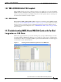
1.4 Troubleshooting Wideband Electrical Card(WBE-28 and WBE-84 Cards) FEAC on DS3 Ports
1.4.1 FEAC Send Code 1-26
1.4.2 WBE-28/WBE-84 Inhibit FEAC Loopback 1-27
1.4.3 FEAC Alarms 1-27
1.5 Troubleshooting WBE-28 and WBE-84 Cards with Far End Loopcodes on DS1 Ports
1.5.1 FEAC Send Code 1-28
1.5.2 WBE-28/WBE-84 Inhibit FEAC Loopback 1-28
1.6 Troubleshooting Ethernet Circuit Paths With Loopbacks 1-28
1.6.1 Perform a Facility Loopback on a Source-Node Ethernet Port 1-29
Create the Facility Loopback on the Source-Node Ethernet Port 1-29
Test and Clear the Facility Loopback Circuit 1-29
Test the Ethernet Card 1-30
1.6.2 Perform a Terminal Loopback on a Source-Node Ethernet Port 1-31
Create the Terminal Loopback on a Source-Node Ethernet Port 1-31
Test and Clear the Ethernet Terminal Loopback Circuit 1-32
Cisco ONS 15310-CL and Cisco ONS 15310-MA Troubleshooting Guide, R7.0
iv
1-27
1-25
Contents
Test the Ethernet Card 1-33
1.6.3 Perform a Facility Loopback on an Intermediate-Node OC-N Port 1-33
Create a Facility Loopback on an Intermediate-Node OC-N Port 1-34
Test and Clear the OC-N Facility Loopback Circuit 1-35
Test the OC-N (Controller) Card 1-35
1.6.4 Perform a Terminal Loopback on Intermediate-Node OC-N Ports 1-36
Create a Terminal Loopback on Intermediate-Node OC-N Ports 1-37
Test and Clear the OC-N Terminal Loopback Circuit 1-38
Test the OC-N Card 1-38
1.6.5 Perform a Facility Loopback on a Destination-Node Ethernet Port 1-39
Create the Facility Loopback on a Destination-Node Ethernet Port 1-40
Test and Clear the Ethernet Facility Loopback Circuit 1-41
Test the Ethernet Card 1-41
1.6.6 Perform a Terminal Loopback on a Destination-Node Ethernet Port 1-42
Create the Terminal Loopback on a Destination-Node Ethernet Port 1-42
Test and Clear the Ethernet Terminal Loopback Circuit 1-44
Test the Ethernet Card 1-44
1.7 Restore the Database and Default Settings
1.7.1 Restore the Node Database 1-45
1-45
1.8 PC Connectivity Troubleshooting 1-45
1.8.1 Windows PC System Minimum Requirements 1-46
1.8.2 Sun, Solaris, or UNIX System Minimum Requirements 1-46
1.8.3 Supported Platforms, Browsers, and JREs 1-46
1.8.4 Unsupported Platforms and Browsers 1-47
1.8.5 Unable to Verify the IP Configuration of Your Windows PC 1-47
Verify the IP Configuration of Your Windows PC 1-47
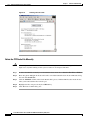
1.8.6 Browser Login Does Not Launch Java 1-48
Reconfigure the Windows PC Operating System Java Plug-in Control Panel
Reconfigure the Browser 1-49
1.8.7 Unable to Verify the NIC Connection on Your Windows PC 1-49
1.8.8 Verify Windows PC Connection to the Node (Ping) 1-50
Ping the ONS 15310-CL or ONS 15310-MA 1-51
1-48
1.9 CTC Operation Troubleshooting 1-51
1.9.1 Unable to Launch CTC Help After Removing Netscape 1-51
Set Internet Explorer as the Default Browser for CTC 1-52
1.9.2 Unable to Change Node View to Network View 1-52
Set the CTC_HEAP and CTC_MAX_PERM_SIZE_HEAP Environment Variables for
Windows 1-52
Set the CTC_HEAP and CTC_MAX_PERM_SIZE_HEAP Environment Variables for Solaris
1.9.3 Browser Stalls When Downloading CTC JAR Files from port 1-53
1-53
Cisco ONS 15310-CL and Cisco ONS 15310-MA Troubleshooting Guide, R7.0
v
Contents
Disable the VirusScan Download Scan 1-54
1.9.4 CTC Does Not Launch 1-54
Redirect the Netscape Cache to a Valid Directory 1-54
1.9.5 Sluggish CTC Operation or Login Problems 1-55
Delete the CTC Cache File Automatically 1-55
Delete the CTC Cache File Manually 1-56
1.9.6 Node Icon is Gray on CTC Network View 1-57
1.9.7 Java Runtime Environment Incompatible 1-58
Launch CTC to Correct the Core Version Build 1-58
1.9.8 Different CTC Releases Do Not Recognize Each Other 1-59
Launch CTC to Correct the Core Version Build 1-59
1.9.9 Username or Password Does Not Match the Port Information
Verify Correct Username and Password 1-60
1.9.10 Superuser Password Needs to Be Reset 1-60
Reset the ONS 15310-CL or ONS 15310-MA Password 1-61
1.9.11 No IP Connectivity Exists Between Nodes 1-61
1.9.12 DCC Connection Lost 1-62
1.9.13 “Path in Use” Error When Creating a Circuit 1-62
Cancel the Circuit Creation and Start Over 1-62
1.9.14 Calculate and Design IP Subnets 1-63
1.10 Circuits and Timing 1-63
1.10.1 Circuit Transitions to Partial Status 1-63
View the State of Circuit Nodes 1-64
1.10.2 Circuits Remain in PARTIAL Status 1-64
1.10.3 AIS-V on Unused 15310-CL-CTX Card VT Circuits 1-65
Clear AIS-V on Unused Controller Card VT Circuits 1-65
1.10.4 Circuit Creation Error with VT1.5 Circuit 1-66
1.10.5 OC-3 and DCC Limitations 1-66
1.10.6 ONS 15310-CL or ONS 15310-MA Switches Timing Reference
1.10.7 Holdover Synchronization Alarm 1-67
1.10.8 Free-Running Synchronization Mode 1-68
1.10.9 Daisy-Chained BITS Not Functioning 1-68
1.10.10 Blinking STAT LED after Installing a Card 1-68
1.11 Fiber and Cabling 1-69
1.11.1 Bit Errors Appear for a Traffic Card 1-69
1.11.2 Faulty Fiber-Optic Connections 1-69
Verify Fiber-Optic Connections 1-70
1.11.2.1 Crimp Replacement LAN Cables 1-71
1.12 Power and LED Tests
1-73
Cisco ONS 15310-CL and Cisco ONS 15310-MA Troubleshooting Guide, R7.0
vi
1-60
1-67
Contents
1.12.1 Power Supply Problems 1-73
1.12.2 Power Consumption for Node and Cards
1.12.3 Lamp Tests for Card LEDs 1-75
Verify Card LED Operation 1-75
CHAPTER
2
Alarm Troubleshooting
1-74
2-1
2.1 Alarm Index by Default Severity 2-1
2.1.1 Critical Alarms (CR) 2-2
2.1.2 Major Alarms (MJ) 2-2
2.1.3 Minor Alarms (MN) 2-3
2.1.4 Not Alarmed Conditions 2-4
2.1.5 Not Reported (NR) Conditions 2-6
2.2 Alarms and Conditions Indexed By Alphabetical Entry
2.3 Alarm Logical Objects
2-6
2-9
2.4 Alarm List by Logical Object Type
2-10
2.5 Trouble Notifications 2-14
2.5.1 Alarm Characteristics 2-14
2.5.2 Condition Characteristics 2-14
2.5.3 Severities 2-14
2.5.4 Alarm Hierarchy 2-15
2.5.5 Service Effect 2-17
2.5.6 States 2-17
2.6 Safety Summary
2-17
2.7 Alarm Procedures 2-18
2.7.1 AIS 2-18
Clear the AIS Condition 2-18
2.7.2 AIS-L 2-18
Clear the AIS-L Condition 2-19
2.7.3 AIS-P 2-19
Clear the AIS-P Condition 2-19
2.7.4 AIS-V 2-19
Clear the AIS-V Condition 2-19
2.7.5 ALS 2-20
2.7.6 APC-END 2-20
2.7.7 APSB 2-20
Clear the APSB Alarm 2-20
2.7.8 APSCDFLTK 2-20
2.7.9 APSC-IMP 2-20
2.7.10 APSCINCON 2-21
Cisco ONS 15310-CL and Cisco ONS 15310-MA Troubleshooting Guide, R7.0
vii
Contents
Clear the APSCINCON Alarm 2-21
2.7.11 APSCM 2-21
Clear the APSCM Alarm 2-21
2.7.12 APSCNMIS 2-22
2.7.13 APSIMP 2-22
Clear the APSIMP Alarm 2-22
2.7.14 APS-INV-PRIM 2-23
2.7.15 APSMM 2-23
Clear the APSMM Alarm 2-23
2.7.16 APS-PRIM-FAC 2-24
Clear the APS-PRIM-FAC Condition 2-24
2.7.17 APS-PRIM-SEC-MISM 2-24
Clear the APS-PRIM-SEC-MISM Alarm 2-24
2.7.18 AS-CMD 2-24
Clear the AS-CMD Condition 2-25
2.7.19 AS-MT 2-25
Clear the AS-MT Condition 2-26
2.7.20 AS-MT-OOG 2-26
2.7.21 AUD-LOG-LOSS 2-26
Clear the AUD-LOG-LOSS Condition 2-26
2.7.22 AUD-LOG-LOW 2-27
2.7.23 AUTOLSROFF 2-27
2.7.24 AUTORESET 2-27
Clear the AUTORESET Alarm 2-27
2.7.25 AUTOSW-AIS 2-28
Clear the AUTOSW-AIS Condition 2-28
2.7.26 AUTOSW-LOP (STSMON) 2-28
Clear the AUTOSW-LOP (STSMON) Condition 2-29
2.7.27 AUTOSW-LOP (VT-MON) 2-29
Clear the AUTOSW-LOP (VT-MON) Alarm 2-29
2.7.28 AUTOSW-PDI 2-29
Clear the AUTOSW-PDI Condition 2-29
2.7.29 AUTOSW-SDBER 2-30
Clear the AUTOSW-SDBER Condition 2-30
2.7.30 AUTOSW-SFBER 2-30
Clear the AUTOSW-SFBER Condition 2-30
2.7.31 AUTOSW-UNEQ (STSMON) 2-31
Clear the AUTOSW-UNEQ (STSMON) Condition 2-31
2.7.32 AUTOSW-UNEQ (VT-MON) 2-31
Clear the AUTOSW-UNEQ (VT-MON) Alarm 2-31
Cisco ONS 15310-CL and Cisco ONS 15310-MA Troubleshooting Guide, R7.0
viii
Contents
2.7.33 BAT-FAIL 2-31
Clear the BAT-FAIL Alarm 2-32
2.7.34 BKUPMEMP 2-32
Clear the BKUPMEMP Alarm 2-32
2.7.35 BLSROSYNC 2-33
2.7.36 CARLOSS (CE100T) 2-33
lear the CARLOSS (CE100T) Alarm 2-33
2.7.37 CARLOSS (EQPT) 2-35
Clear the CARLOSS (EQPT) Alarm 2-36
2.7.38 CLDRESTART 2-37
Clear the CLDRESTART Condition 2-37
2.7.39 COMIOXC 2-37
Clear the COMIOXC Alarm 2-37
2.7.40 CONTBUS-CLK-A 2-38
Clear the CONTBUS-CLK-A Alarm 2-38
2.7.41 CONTBUS-CLK-B 2-38
Clear the CONTBUS-CLK-B Alarm 2-39
2.7.42 CONTBUS-DISABLED 2-39
Clear the CONTBUS-DISABLED Alarm 2-40
2.7.43 CONTBUS-IO-A 2-40
Clear the CONTBUS-IO-A Alarm 2-40
2.7.44 CTNEQPT-PBPROT 2-41
Clear the CTNEQPT-PBPROT Alarm 2-41
2.7.45 CTNEQPT-PBWORK 2-42
Clear the CTNEQPT-PBWORK Alarm 2-42
2.7.46 DATAFLT 2-43
Clear the DATAFLT Alarm 2-43
2.7.47 DBOSYNC 2-43
Clear the DBOSYNC Alarm 2-43
2.7.48 DISCONNECTED 2-44
Clear the DISCONNECTED Alarm 2-44
2.7.49 DS3-MISM 2-44
Clear the DS3-MISM Condition 2-44
2.7.50 DUP-IPADDR 2-45
Clear the DUP-IPADDR Alarm 2-45
2.7.51 DUP-NODENAME 2-45
Clear the DUP-NODENAME Alarm 2-46
2.7.52 DUP-SHELF-ID 2-46
2.7.53 EHIBATVG 2-46
Clear the EHIBATVG Alarm 2-46
Cisco ONS 15310-CL and Cisco ONS 15310-MA Troubleshooting Guide, R7.0
ix
Contents
2.7.54 ELWBATVG 2-46
Clear the ELWBATVG Alarm 2-47
2.7.55 ENCAP-MISMATCH-P 2-47
Clear the ENCAP-MISMATCH-P Alarm 2-48
2.7.56 EOC 2-48
Clear the EOC Alarm 2-49
2.7.57 EOC-L 2-50
Clear the EOC-L Alarm 2-51
2.7.58 EQPT 2-51
Clear the EQPT Alarm 2-51
2.7.59 EQPT-MISS 2-52
2.7.60 ERFI-P-CONN 2-52
Clear the ERFI-P-CONN Condition 2-52
2.7.61 ERFI-P-PAYLD 2-53
Clear the ERFI-P-PAYLD Condition 2-53
2.7.62 ERFI-P-SRVR 2-53
Clear the ERFI-P-SRVR Condition 2-53
2.7.63 ERROR-CONFIG 2-53
Clear the ERROR-CONFIG Alarm 2-54
2.7.64 ETH-LINKLOSS 2-55
Clear the ETH-LINKLOSS Condition 2-55
2.7.65 E-W-MISMATCH 2-55
2.7.66 EXCCOL 2-55
Clear the EXCCOL Alarm 2-55
2.7.67 EXT 2-56
Clear the EXT Alarm 2-56
2.7.68 EXTRA-TRAF-PREEMPT 2-56
2.7.69 FAILTOSW 2-56
Clear the FAILTOSW Condition 2-56
2.7.70 FAILTOSW-PATH 2-57
Clear the FAILTOSW-PATH Condition in a Path Protection Configuration
2.7.71 FAN 2-57
2.7.72 FAN-DEGRADE 2-57
2.7.73 FE-AIS 2-58
Clear the FE-AIS Condition 2-58
2.7.74 FE-DS1-MULTLOS 2-58
Clear the FE-DS1-MULTLOS Condition 2-58
2.7.75 FE-DS1-NSA 2-59
Clear the FE-DS1-NSA Condition 2-59
2.7.76 FE-DS1-SA 2-59
Cisco ONS 15310-CL and Cisco ONS 15310-MA Troubleshooting Guide, R7.0
x
2-57
Contents
Clear the FE-DS1-SA Condition 2-59
2.7.77 FE-DS1-SNGLLOS 2-60
Clear the FE-DS1-SNGLLOS Condition 2-60
2.7.78 FE-DS3-NSA 2-60
Clear the FE-DS3-NSA Condition 2-60
2.7.79 FE-DS3-SA 2-61
Clear the FE-DS3-SA Condition 2-61
2.7.80 FE-EQPT-NSA 2-61
Clear the FE-EQPT-NSA Condition 2-61
2.7.81 FE-FRCDWKSWBK-SPAN 2-61
Clear the FE-FRCDWKSWBK-SPAN Condition 2-62
2.7.82 FE-FRCDWKSWPR-SPAN 2-62
2.7.83 FE-IDLE 2-62
Clear the FE-IDLE Condition 2-62
2.7.84 FE-LOCKOUTOFPR-SPAN 2-62
2.7.85 FE-LOF 2-63
Clear the FE-LOF Condition 2-63
2.7.86 FE-LOS 2-63
Clear the FE-LOS Condition 2-63
2.7.87 FE-MANWKSWBK-SPAN 2-63
2.7.88 FE-MANWKSWPR-SPAN 2-64
2.7.89 FEPRLF 2-64
Clear the FEPRLF Alarm 2-64
2.7.90 FORCED-REQ 2-64
Clear the FORCED-REQ Condition 2-64
2.7.91 FORCED-REQ-SPAN 2-65
Clear the FORCED-REQ-SPAN Condition 2-65
2.7.92 FRCDSWTOINT 2-65
2.7.93 FRCDSWTOPRI 2-65
2.7.94 FRCDSWTOSEC 2-66
2.7.95 FRCDSWTOTHIRD 2-66
2.7.96 FRNGSYNC 2-66
Clear the FRNGSYNC Condition 2-66
2.7.97 FSTSYNC 2-67
2.7.98 FULLPASSTHR-BI 2-67
2.7.99 GFP-CSF 2-67
Clear the GFP-CSF Alarm 2-67
2.7.100 GFP-EX-MISMATCH 2-67
Clear the GFP-EX-MISMATCH Alarm 2-68
2.7.101 GFP-LFD 2-68
Cisco ONS 15310-CL and Cisco ONS 15310-MA Troubleshooting Guide, R7.0
xi
Contents
Clear the GFP-LFD Alarm 2-68
2.7.102 GFP-UP-MISMATCH 2-68
Clear the GFP-UP-MISMATCH Alarm 2-69
2.7.103 HELLO 2-69
Clear the HELLO Alarm 2-69
2.7.104 HIBATVG 2-70
Clear the HIBATVG Alarm 2-70
2.7.105 HI-LASERBIAS 2-70
Clear the HI-LASERBIAS Alarm 2-70
2.7.106 HI-LASERTEMP 2-71
Clear the HI-LASERTEMP Alarm 2-71
2.7.107 HI-RXPOWER 2-72
Clear the HI-RXPOWER Alarm 2-72
2.7.108 HITEMP 2-72
Clear the HITEMP Alarm 2-72
2.7.109 HI-TXPOWER 2-73
Clear the HI-TXPOWER Alarm 2-73
2.7.110 HLDOVRSYNC 2-73
Clear the HLDOVRSYNC Alarm 2-74
2.7.111 I-HITEMP 2-74
Clear the I-HITEMP Alarm 2-75
2.7.112 IMPROPRMVL 2-75
Clear the IMPROPRMVL Alarm 2-75
2.7.113 INC-ISD 2-77
2.7.114 INCOMPATIBLE-SEND-PDIP 2-77
Clear the INCOMPATIBLE-SEND-PDIP Alarm 2-77
2.7.115 INCOMPATIBLE-SW 2-77
Clear the INCOMPATIBLE-SW Alarm 2-77
2.7.116 INHSWPR 2-78
Clear the INHSWPR Condition 2-78
2.7.117 INHSWWKG 2-78
2.7.118 INTRUSION-PSWD 2-78
Clear the INTRUSION-PSWD Condition 2-79
2.7.119 INVMACADR 2-79
2.7.120 IOSCFGCOPY 2-79
2.7.121 ISIS-ADJ-FAIL 2-79
Clear the ISIS-ADJ-FAIL Alarm 2-80
2.7.122 KB-PASSTHR 2-81
2.7.123 LASEREOL 2-81
2.7.124 LCAS-CRC 2-81
Cisco ONS 15310-CL and Cisco ONS 15310-MA Troubleshooting Guide, R7.0
xii
Contents
Clear the LCAS-CRC Condition 2-82
2.7.125 LCAS-RX-FAIL 2-82
0.0.1 LCAS-RX-FAIL 2-82
Clear the LCAS-RX-FAIL Condition 2-82
Clear the LCAS-RX-FAIL Condition 2-83
2.7.126 LCAS-TX-ADD 2-83
2.7.127 LCAS-TX-DNU 2-83
2.7.128 LKOUTPR-S 2-84
Clear the LKOUTPR-S Condition 2-84
2.7.129 LOA 2-84
Clear the LOA Alarm 2-84
2.7.130 LOCKOUT-REQ 2-85
Clear the LOCKOUT-REQ Condition 2-85
2.7.131 LOF (BITS) 2-85
Clear the LOF (BITS) Alarm 2-85
2.7.132 LOF (DS1) 2-86
Clear the LOF (DS1) Alarm 2-86
2.7.133 LOF (DS3) 2-87
Clear the LOF (DS3) Alarm 2-87
2.7.134 LOF (EC1) 2-87
Clear the LOF (EC1) Alarm 2-88
2.7.135 LOF (OCN) 2-88
Clear the LOF (OCN) Alarm 2-88
2.7.136 LOF (STSTRM) 2-88
Clear the LOF (STSTRM) Alarm 2-89
2.7.137 LOGBUFR90 2-89
2.7.138 LOGBUFROVFL 2-89
Clear the LOGBUFROVFL Alarm 2-89
2.7.139 LO-LASERBIAS 2-90
Clear the LO-LASERBIAS Alarm 2-90
2.7.140 LO-LASERTEMP 2-90
2.7.141 LOM 2-91
Clear the LOM Alarm 2-91
2.7.142 LOP-P 2-91
Clear the LOP-P Alarm 2-91
2.7.143 LOP-V 2-92
Clear the LOP-V Alarm 2-92
2.7.144 LO-RXPOWER 2-92
Clear the LO-RXPOWER Alarm 2-92
2.7.145 LOS (BITS) 2-93
Cisco ONS 15310-CL and Cisco ONS 15310-MA Troubleshooting Guide, R7.0
xiii
Contents
Clear the LOS (BITS) Alarm 2-93
2.7.146 LOS (DS1) 2-94
Clear the LOS (DS1) Alarm 2-94
2.7.147 LOS (DS3) 2-95
Clear the LOS (DS3) Alarm 2-95
2.7.148 LOS (EC1) 2-96
Clear the LOS (EC1) Alarm 2-97
2.7.149 LOS (FUDC) 2-97
Clear the LOS (FUDC) Alarm 2-98
2.7.150 LOS (OCN) 2-98
Clear the LOS (OCN) Alarm 2-99
2.7.151 LO-TXPOWER 2-100
Clear the LO-TXPOWER Alarm 2-100
2.7.152 LPBKCRS 2-100
Clear the LPBKCRS Condition 2-101
2.7.153 LPBKDS3FEAC 2-101
Clear the LPBKDS3FEAC Condition 2-101
2.7.154 LPBKDS3FEAC-CMD 2-101
2.7.155 LPBKFACILITY (CE100T) 2-102
Clear the LPBKFACILITY (CE100T) Condition 2-102
2.7.156 LPBKFACILITY (DS1, DS3) 2-102
Clear the LPBKFACILITY (DS1, DS3) Condition 2-103
2.7.157 LPBKFACILITY (EC1) 2-103
Clear the LPBKFACILITY (EC1) Condition 2-103
2.7.158 LPBKFACILITY (OCN) 2-103
Clear the LPBKFACILITY (OCN) Condition 2-104
2.7.159 LPKTERMINAL (CE100T) 2-104
Clear the LPBKTERMINAL (CE100T) Condition 2-104
2.7.160 LPBKTERMINAL (DS1, DS3) 2-104
Clear the LPBKTERMINAL (DS1, DS3) Condition 2-105
2.7.161 LPBKTERMINAL (EC1) 2-105
Clear the LPBKTERMINAL (EC1) Condition 2-105
2.7.162 LPBKTERMINAL (OCN) 2-105
Clear the LPBKTERMINAL (OCN) Condition 2-106
2.7.163 LWBATVG 2-106
Clear the LWBATVG Alarm 2-106
2.7.164 MAN-REQ 2-106
Clear the MAN-REQ Condition 2-107
2.7.165 MANRESET 2-107
2.7.166 MANSWTOINT 2-107
Cisco ONS 15310-CL and Cisco ONS 15310-MA Troubleshooting Guide, R7.0
xiv
Contents
2.7.167 MANSWTOPRI 2-107
2.7.168 MANSWTOSEC 2-107
2.7.169 MANSWTOTHIRD 2-108
2.7.170 MANUAL-REQ-SPAN 2-108
Clear the MANUAL-REQ-SPAN Condition
2.7.171 MATECLK 2-108
Clear the MATECLK Alarm 2-109
2.7.172 MEA (EQPT) 2-109
Clear the MEA (EQPT) Alarm 2-109
2.7.173 MEA (FAN) 2-110
2.7.174 MEA (PPM) 2-110
2.7.175 MEM-GONE 2-111
2.7.176 MEM-LOW 2-111
2.7.177 MFGMEM 2-111
2.7.178 NO-CONFIG 2-111
Clear the NO-CONFIG Condition 2-112
2.7.179 NOT-AUTHENTICATED 2-112
2.7.180 OOU-TPT 2-112
Clear the OOT-TPT Condition 2-113
2.7.181 OPEN-SLOT 2-113
Clear the OPEN-SLOT Condition 2-113
2.7.182 PDI-P 2-113
Clear the PDI-P Condition 2-114
2.7.183 PLM-P 2-115
Clear the PLM-P Alarm 2-115
2.7.184 PLM-V 2-115
Clear the PLM-V Alarm 2-116
2.7.185 PRC-DUPID 2-116
2.7.186 PROTNA 2-116
Clear the PROTNA Alarm 2-116
2.7.187 PROV-MISMATCH 2-117
2.7.188 PWR-FAIL-A 2-117
Clear the PWR-FAIL-A Alarm 2-117
2.7.189 PWR-FAIL-B 2-118
Clear the PWR-FAIL-B Alarm 2-118
2.7.190 RAI 2-118
Clear the RAI Condition 2-118
2.7.191 RFI-L 2-118
Clear the RFI-L Condition 2-119
2.7.192 RFI-P 2-119
2-108
Cisco ONS 15310-CL and Cisco ONS 15310-MA Troubleshooting Guide, R7.0
xv
Contents
Clear the RFI-P Condition 2-119
2.7.193 RFI-V 2-120
Clear the RFI-V Condition 2-120
2.7.194 ROLL 2-120
2.7.195 ROLL-PEND 2-121
2.7.196 RPRW 2-121
Clear the RPRW Condition 2-121
2.7.197 RUNCFG-SAVENEED 2-121
2.7.198 SD 2-122
Clear the SD (DS1, DS3) Condition 2-123
2.7.199 SD-L 2-123
Clear the SD-L Condition 2-124
2.7.200 SD-P 2-124
Clear the SD-P Condition 2-125
2.7.201 SD-V 2-125
Clear the SD-V Condition 2-125
2.7.202 SF 2-125
Clear the SF (DS1, DS3) Condition 2-126
2.7.203 SF-L 2-126
Clear the SF-L Condition 2-126
2.7.204 SF-P 2-126
Clear the SF-P Condition 2-127
2.7.205 SFTWDOWN 2-127
2.7.206 SF-V 2-127
Clear the SF-V Condition 2-127
2.7.207 SHELF-COMM-FAIL 2-127
2.7.208 SNTP-HOST 2-128
Clear the SNTP-HOST Alarm 2-128
2.7.209 SQUELCH 2-128
2.7.210 SQUELCHED 2-128
2.7.211 SQM 2-129
Clear the SQM Alarm 2-129
2.7.212 SSM-DUS 2-129
2.7.213 SSM-FAIL 2-129
Clear the SSM-FAIL Alarm 2-130
2.7.214 SSM-OFF 2-130
Clear the SSM-OFF Condition 2-130
2.7.215 SSM-PRS 2-130
2.7.216 SSM-RES 2-130
2.7.217 SSM-SMC 2-131
Cisco ONS 15310-CL and Cisco ONS 15310-MA Troubleshooting Guide, R7.0
xvi
Contents
2.7.218 SSM-ST2 2-131
2.7.219 SSM-ST3 2-131
2.7.220 SSM-ST3E 2-131
2.7.221 SSM-ST4 2-132
2.7.222 SSM-STU 2-132
Clear the SSM-STU Condition 2-132
2.7.223 SSM-TNC 2-132
2.7.224 STS-SQUELCH-L 2-133
2.7.225 SW-MISMATCH 2-133
2.7.226 SWMTXMOD-PROT 2-133
Clear the SWMTXMOD-PROT Alarm 2-133
2.7.227 SWMTXMOD-WORK 2-134
Clear the SWMTXMOD-WORK Alarm 2-134
2.7.228 SWTOPRI 2-134
2.7.229 SWTOSEC 2-134
Clear the SWTOSEC Condition 2-134
2.7.230 SWTOTHIRD 2-135
Clear the SWTOTHIRD Condition 2-135
2.7.231 SYNC-FREQ 2-135
Clear the SYNC-FREQ Condition 2-135
2.7.232 SYNCPRI 2-135
Clear the SYNCPRI Alarm 2-136
2.7.233 SYNCSEC 2-136
Clear the SYNCSEC Alarm 2-136
2.7.234 SYNCTHIRD 2-137
Clear the SYNCTHIRD Alarm 2-137
2.7.235 SYSBOOT 2-137
2.7.236 TIM 2-137
Clear the TIM Alarm 2-138
2.7.237 TIM-MON 2-139
2.7.238 TIM-P 2-139
Clear the TIM-P Alarm 2-139
2.7.239 TIM-S 2-139
Clear the TIM-S Alarm 2-140
2.7.240 TIM-V 2-140
Clear the TIM-V Alarm 2-140
2.7.241 TPTFAIL (CE100T) 2-140
Clear the TPTFAIL (CE100T) Alarm 2-141
2.7.242 TX-AIS 2-141
Clear the TX-AIS Condition 2-141
Cisco ONS 15310-CL and Cisco ONS 15310-MA Troubleshooting Guide, R7.0
xvii
Contents
2.7.243 TX-LOF 2-141
Clear the TX-LOF Condition 2-141
2.7.244 TX-RAI 2-142
Clear the TX-RAI Condition 2-142
2.7.245 UNEQ-P 2-142
Clear the UNEQ-P Alarm 2-142
2.7.246 UNEQ-V 2-144
Clear the UNEQ-V Alarm 2-144
2.7.247 VCG-DEG 2-144
Clear the VCG-DEG Condition 2-145
2.7.248 VCG-DOWN 2-145
Clear the VCG-DOWN Condition 2-145
2.7.249 VT-SQUELCH-L 2-145
2.7.250 WKSWPR 2-146
Clear the WKSWPR Condition 2-146
2.7.251 WTR 2-146
2.8 DS-1 Line Alarms
2-146
2.9 Traffic Card LED Activity 2-147
2.9.1 Typical Controller Card or Ethernet Card LED Activity After Insertion
2.9.2 Typical Card LED Activity During Reset 2-147
2-147
2.10 Frequently Used Alarm Troubleshooting Procedures 2-147
2.10.1 Protection Switching, Lock Initiation, and Clearing 2-147
Initiate a 1+1 Protection Port Force Switch Command 2-148
Initiate a 1+1 Manual Switch Command 2-148
Clear a 1+1 Force or Manual Switch Command 2-149
Initiate a Lock-On Command 2-149
Initiate a Card or Port Lockout Command 2-150
Clear a Lock-On or Lockout Command 2-150
Initiate an ONS 15310-MA 1:1 Card Switch Command 2-150
Initiate a Force Switch for All Circuits on a Path Protection Span 2-151
Initiate a Manual Switch for All Circuits on a Path Protection Span 2-151
Initiate a Lockout for All Circuits on a Protect Path Protection Span 2-152
Clear an External Switching Command on a Path Protection Span 2-152
2.10.2 CTC Card Resetting and Switching 2-153
Soft- or Hard-Reset an Ethernet or Electrical Card in CTC 2-153
Soft- or Hard-Reset a Controller Card 2-153
2.10.3 Physical Card Reseating and Replacement 2-154
Remove and Reinsert (Reseat) a Card 2-154
Physically Replace a Card 2-154
Cisco ONS 15310-CL and Cisco ONS 15310-MA Troubleshooting Guide, R7.0
xviii
Contents
2.10.4 Generic Signal and Circuit Procedures 2-155
Verify the Signal BER Threshold Level 2-155
Delete a Circuit 2-155
Verify or Create Node DCC Terminations 2-155
Clear an OC-N Port Facility or Terminal Loopback Circuit
Clear an OC-N Port XC Loopback Circuit 2-156
Clear a DS-3 or DS-1 Port Loopback Circuit 2-156
Clear an EC-1 Port Loopback 2-157
Clear an Ethernet Card Loopback Circuit 2-157
CHAPTER
3
Transient Conditions
2-156
3-1
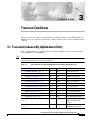
3.1 Transients Indexed By Alphabetical Entry
3.2 Trouble Notifications 3-3
3.2.1 Condition Characteristics
3.2.2 Condition States 3-3
3-1
3-3
3.3 Transient Conditions 3-4
3.3.1 ADMIN-DISABLE 3-4
3.3.2 ADMIN-DISABLE-CLR 3-4
3.3.3 ADMIN-LOCKOUT 3-4
3.3.4 ADMIN-LOCKOUT-CLR 3-4
3.3.5 ADMIN-LOGOUT 3-4
3.3.6 ADMIN-SUSPEND 3-4
3.3.7 ADMIN-SUSPEND-CLR 3-5
3.3.8 AUD-ARCHIVE-FAIL 3-5
3.3.9 DBBACKUP-FAIL 3-5
3.3.10 DBRESTORE-FAIL 3-5
3.3.11 FIREWALL-DIS 3-5
3.3.12 FRCDWKSWBK-NO-TRFSW 3-5
3.3.13 FRCDWKSWPR-NO-TRFSW 3-6
3.3.14 INTRUSION 3-6
3.3.15 INTRUSION-PSWD 3-6
3.3.16 LOGIN-FAILURE-LOCKOUT 3-6
3.3.17 LOGIN-FAILURE-ONALRDY 3-6
3.3.18 LOGIN-FAILURE-PSWD 3-6
3.3.19 LOGIN-FAILURE-USERID 3-6
3.3.20 LOGOUT-IDLE-USER 3-7
3.3.21 MANWKSWBK-NO-TRFSW 3-7
3.3.22 MANWKSWPR-NO-TRFSW 3-7
3.3.23 PM-TCA 3-7
Cisco ONS 15310-CL and Cisco ONS 15310-MA Troubleshooting Guide, R7.0
xix
Contents
3.3.24
3.3.25
3.3.26
3.3.27
3.3.28
3.3.29
3.3.30
3.3.31
3.3.32
3.3.33
3.3.34
3.3.35
CHAPTER
4
PS 3-7
PSWD-CHG-REQUIRED 3-7
RMON-ALARM 3-7
RMON-RESET 3-8
SESSION-TIME-LIMIT 3-8
SFTWDOWN-FAIL 3-8
USER-LOCKOUT 3-8
USER-LOGIN 3-8
USER-LOGOUT 3-8
WKSWBK 3-8
WKSWPR 3-9
WRMRESTART 3-9
Error Messages
4-1
INDEX
Cisco ONS 15310-CL and Cisco ONS 15310-MA Troubleshooting Guide, R7.0
xx
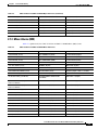
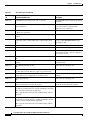
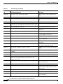
F I G U R E S
Figure 1-1
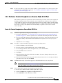
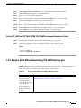
Accessing FEAC Functions on the DS3 ports of WBE-28/WBE-84 Cards
Figure 1-2
Diagram of FEAC Circuit
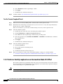
Figure 1-3
Accessing Far End troubleshooting Functions on the WBE Cards
Figure 1-4
Deleting the CTC Cache
Figure 1-5
RJ-45 Pin Numbers
Figure 1-6
LAN Cable Layout
Figure 1-7
Cross-Over Cable Layout
Figure 4-1
Error Dialog Box
1-26
1-26
1-27
1-56
1-71
1-72
1-72
4-1
Cisco ONS 15310-CL and Cisco ONS 15310-MA Troubleshooting Guide, R7.0
xxi
Figures
Cisco ONS 15310-CL and Cisco ONS 15310-MA Troubleshooting Guide, R7.0
xxii
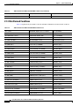
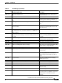
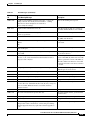
T A B L E S
Table 1-1
Restore the Node Database
Table 1-2
Unable to Verify the IP Configuration of Your Windows PC
Table 1-3
Browser Login Does Not Launch Java
Table 1-4
Unable to Verify the NIC Connection on Your Windows PC
Table 1-5
Verify Windows PC Connection to ONS 15310-CL or ONS 15310-MA (Ping)
Table 1-6
Unable to Launch CTC Help After Removing Netscape
Table 1-7
Unable to Change Node View to Network View
Table 1-8
Browser Stalls When Downloading JAR File from Port
Table 1-9
CTC Does Not Launch
Table 1-10
Sluggish CTC Operation or Login Problems
Table 1-11
Node Icon is Gray on CTC Network View
1-57
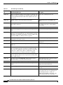
Table 1-12
Java Runtime Environment Incompatible
1-58
Table 1-13
Different CTC Releases Do Not Recognize Each Other
Table 1-14
Username or Password Does Not Match the Port Information
Table 1-15
No IP Connectivity Exists Between Nodes
1-60
Table 1-16
No IP Connectivity Exists Between Nodes
1-61
Table 1-17
DCC Connection Lost
Table 1-18
“Path in Use” Error When Creating a Circuit
Table 1-19
Calculate and Design IP Subnets
Table 1-20
Circuit in Partial Status
Table 1-21
Circuits Remain in PARTIAL Status
Table 1-22
AIS-V on Unused 15310-CL-CTX Card VT Circuits
Table 1-23
Circuit Creation Error with VT1.5 Circuit
Table 1-24
OC-3 and DCC Limitations
Table 1-25
ONS 15310-CL or ONS 15310-MA Switches Timing Reference
Table 1-26
Holdover Synchronization Alarm
Table 1-27
Free-Running Synchronization Mode
1-68
Table 1-28
Daisy-Chained BITS Not Functioning
1-68
Table 1-29
Blinking STAT LED on Installed Card
1-68
Table 1-30
Bit Errors Appear for a Line Card
Table 1-31
Faulty Fiber-Optic Connections
1-45
1-47
1-48
1-50
1-50
1-51
1-52
1-53
1-54
1-55
1-59
1-60
1-62
1-62
1-63
1-63
1-64
1-65
1-66
1-66
1-67
1-67
1-69
1-69
Cisco ONS 15310-CL and Cisco ONS 15310-MA Troubleshooting Guide, R7.0
xxiii
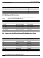
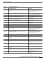
Tables
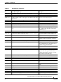
Table 1-32
LAN Cable Pinout
Table 1-33
Cross-Over Cable Pinout
1-72
Table 1-34
Power Supply Problems
1-74
Table 1-35
Power Consumption for Node and Cards
Table 1-36
Lamp Test for Optical and Electrical Card LEDs
Table 2-1
ONS 15310-CL and ONS 15310-MA Critical Alarm List
Table 2-2
ONS 15310-CL and ONS 15310-MA Major Alarm List
2-2
Table 2-3
ONS 15310-CL and ONS 15310-MA Minor Alarm List
2-3
Table 2-4
ONS 15310-CL and ONS 15310-MA NA Conditions List
Table 2-5
ONS 15310-CL and ONS 15310-MA Major Alarm List
Table 2-6
ONS 15310-CL and ONS 15310-MA Alarm and Condition Alphabetical List
Table 2-7
Alarm Logical Object Type Definitions
Table 2-8
ONS 15310-CL and ONS 15310-MA Alarm List by Logical Object as Shown in Alarm Profile
Table 2-9
Path Alarm Hierarchy
Table 2-10
Facility Alarm Hierarchy
Table 2-11
Near-End Alarm Hierarchy
Table 2-12
Far-End Alarm Hierarchy
Table 2-13
DS-1 Alarms by Line Type
Table 3-1
ONS 15310-CL and ONS 15310-MA Transient Condition Alphabetical List
Table 4-1
Error Messages
1-72
1-74
1-75
2-4
2-6
2-6
2-9
2-15
2-15
2-16
2-16
2-146
4-2
Cisco ONS 15310-CL and Cisco ONS 15310-MA Troubleshooting Guide, R7.0
xxiv
2-2
3-1
2-10
About this Guide
Note
The terms "Unidirectional Path Switched Ring" and "UPSR" may appear in Cisco literature. These terms
do not refer to using Cisco ONS 15xxx products in a unidirectional path switched ring configuration.
Rather, these terms, as well as "Path Protected Mesh Network" and "PPMN," refer generally to Cisco's
path protection feature, which may be used in any topological network configuration. Cisco does not
recommend using its path protection feature in any particular topological network configuration.
This section explains the objectives, intended audience, and organization of this troubleshooting guide
and describes the conventions that convey instructions and other information.
This section provides the following information:
•
Document Objectives
•
Audience
•
Document Organization
•
Related Documentation
•
Document Conventions
•
Obtaining Optical Networking Information
•
Obtaining Documentation, Obtaining Support, and Security Guidelines
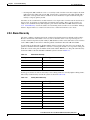
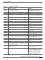
Revision History
Date
Notes
03/19/2007
Revision History Table added for the first time
03/23/2007
Corrected product part numbers for the UBIC-V and UBIC-H
DS3 cables.
04/16/2007
Added additional description for APSCM alarm in the Alarm
Troubleshooting chapter.
07/17/2001
Updated About this Guide chapter.
Cisco ONS 15310-CL and Cisco ONS 15310-MA Troubleshooting Guide, R7.0
xxv
About this Guide
Document Objectives
Date
Notes
08/01/2007
Replaced TX Power High column name with OPT-HIGH in the
HI-TX Power section of the Alarm Troubleshooting chapter.
09/03/2007
Added a note on AIS downstream limitations on the of terminal
loopback in the General Troubleshooting chapter.
Document Objectives
This guide gives general troubleshooting instructions, alarm troubleshooting instructions, equipment
replacement instructions, and a list of error messages that apply to the ONS 15310-CL equipment. This
information is contained in four chapters. Use this guide in conjunction with the appropriate publications
listed in the Related Documentation section.
Audience
To use this publication, you should be familiar with Cisco or equivalent optical transmission hardware
and cabling, telecommunications hardware and cabling, electronic circuitry and wiring practices, and
preferably have experience as a telecommunications technician.
Document Organization
The Cisco ONS 15310-CL and Cisco ONS 15310-MA Troubleshooting Guide is organized into the
following chapters:
•
Chapter 1, “General Troubleshooting,” provides methods to discover hardware errors, such as failed
ports, that adversely affect signal traffic; it also gives typical software problems that occur and their
solutions.
•
Chapter 2, “Alarm Troubleshooting,” provides indexes, descriptions, and troubleshooting methods
for all alarms and conditions generated by the ONS system.
•
Chapter 3, “Transient Conditions,” describes transient (temporary) conditions.
•
Chapter 4, “Error Messages,” lists ONS 15310-CL error messages and their definitions.
Related Documentation
Use the Cisco ONS 15310-CL and Cisco ONS 15310-MA Troubleshooting Guide in conjunction with the
following publications:
•
Cisco ONS 15310-CL and Cisco ONS 15310-MA Procedure Guide
Provides installation, turn up, test, and maintenance procedures.
•
Cisco ONS 15310-CL and Cisco ONS 15310-MA Reference Manual
Provides detailed card specifications, hardware and software feature descriptions, network topology
information, and network element defaults.
Cisco ONS 15310-CL and Cisco ONS 15310-MA Troubleshooting Guide, R7.0
xxvi
About this Guide
Document Conventions
•
Cisco ONS SONET TL1 Command Guide
Provides a full TL1 command and autonomous message set including parameters, AIDs, conditions
and modifiers for the Cisco ONS 15454, ONS 15327, ONS 15600, ONS 15310-CL, and
ONS 15310-MA systems.
•
Cisco ONS SONET TL1 Reference Guide
Provides general information, procedures, and errors for TL1 in the Cisco ONS 15454, ONS 15327,
ONS 15600, ONS 15310-CL, and ONS 15310-MA systems.
•
Cisco ONS 15310-CL and Cisco ONS 15310-MA Ethernet Card Software Feature and Configuration
Guide
Provides software feature and operation information for Ethernet cards in the Cisco ONS 15310-CL
and Cisco ONS 15310-MA.
•
Release Notes for the Cisco ONS 15310-CL Release 7.0
Provides caveats, closed issues, and new feature and functionality information.
•
Release Notes for the Cisco ONS 15310-MA Release 7.0
Provides caveats, closed issues, and new feature and functionality information.
Refer to the following standards documentation referenced in this publication:
•
Telcordia GR-253 CORE
For an update on End-of-Life and End-of-Sale notices, refer to
http://cisco.com/en/US/products/hw/optical/ps2001/prod_eol_notices_list.html.
Document Conventions
This publication uses the following conventions:
Convention
Application
boldface
Commands and keywords in body text.
italic
Command input that is supplied by the user.
[
Keywords or arguments that appear within square brackets are optional.
]
{x|x|x}
A choice of keywords (represented by x) appears in braces separated by
vertical bars. The user must select one.
Ctrl
The control key. For example, where Ctrl + D is written, hold down the
Control key while pressing the D key.
screen font
Examples of information displayed on the screen.
boldface screen font
Examples of information that the user must enter.
<
Command parameters that must be replaced by module-specific codes.
>
Cisco ONS 15310-CL and Cisco ONS 15310-MA Troubleshooting Guide, R7.0
xxvii
About this Guide
Document Conventions
Note
Means reader take note. Notes contain helpful suggestions or references to material not covered in the
document.
Caution
Means reader be careful. In this situation, the user might do something that could result in equipment
damage or loss of data.
Warning
IMPORTANT SAFETY INSTRUCTIONS
This warning symbol means danger. You are in a situation that could cause bodily injury. Before you
work on any equipment, be aware of the hazards involved with electrical circuitry and be familiar
with standard practices for preventing accidents. Use the statement number provided at the end of
each warning to locate its translation in the translated safety warnings that accompanied this
device. Statement 1071
SAVE THESE INSTRUCTIONS
Waarschuwing
BELANGRIJKE VEILIGHEIDSINSTRUCTIES
Dit waarschuwingssymbool betekent gevaar. U verkeert in een situatie die lichamelijk letsel kan
veroorzaken. Voordat u aan enige apparatuur gaat werken, dient u zich bewust te zijn van de bij
elektrische schakelingen betrokken risico's en dient u op de hoogte te zijn van de standaard
praktijken om ongelukken te voorkomen. Gebruik het nummer van de verklaring onderaan de
waarschuwing als u een vertaling van de waarschuwing die bij het apparaat wordt geleverd, wilt
raadplegen.
BEWAAR DEZE INSTRUCTIES
Varoitus
TÄRKEITÄ TURVALLISUUSOHJEITA
Tämä varoitusmerkki merkitsee vaaraa. Tilanne voi aiheuttaa ruumiillisia vammoja. Ennen kuin
käsittelet laitteistoa, huomioi sähköpiirien käsittelemiseen liittyvät riskit ja tutustu
onnettomuuksien yleisiin ehkäisytapoihin. Turvallisuusvaroitusten käännökset löytyvät laitteen
mukana toimitettujen käännettyjen turvallisuusvaroitusten joukosta varoitusten lopussa näkyvien
lausuntonumeroiden avulla.
SÄILYTÄ NÄMÄ OHJEET
Attention
IMPORTANTES INFORMATIONS DE SÉCURITÉ
Ce symbole d'avertissement indique un danger. Vous vous trouvez dans une situation pouvant
entraîner des blessures ou des dommages corporels. Avant de travailler sur un équipement, soyez
conscient des dangers liés aux circuits électriques et familiarisez-vous avec les procédures
couramment utilisées pour éviter les accidents. Pour prendre connaissance des traductions des
avertissements figurant dans les consignes de sécurité traduites qui accompagnent cet appareil,
référez-vous au numéro de l'instruction situé à la fin de chaque avertissement.
CONSERVEZ CES INFORMATIONS
Cisco ONS 15310-CL and Cisco ONS 15310-MA Troubleshooting Guide, R7.0
xxviii
About this Guide
Document Conventions
Warnung
WICHTIGE SICHERHEITSHINWEISE
Dieses Warnsymbol bedeutet Gefahr. Sie befinden sich in einer Situation, die zu Verletzungen führen
kann. Machen Sie sich vor der Arbeit mit Geräten mit den Gefahren elektrischer Schaltungen und
den üblichen Verfahren zur Vorbeugung vor Unfällen vertraut. Suchen Sie mit der am Ende jeder
Warnung angegebenen Anweisungsnummer nach der jeweiligen Übersetzung in den übersetzten
Sicherheitshinweisen, die zusammen mit diesem Gerät ausgeliefert wurden.
BEWAHREN SIE DIESE HINWEISE GUT AUF.
Avvertenza
IMPORTANTI ISTRUZIONI SULLA SICUREZZA
Questo simbolo di avvertenza indica un pericolo. La situazione potrebbe causare infortuni alle
persone. Prima di intervenire su qualsiasi apparecchiatura, occorre essere al corrente dei pericoli
relativi ai circuiti elettrici e conoscere le procedure standard per la prevenzione di incidenti.
Utilizzare il numero di istruzione presente alla fine di ciascuna avvertenza per individuare le
traduzioni delle avvertenze riportate in questo documento.
CONSERVARE QUESTE ISTRUZIONI
Advarsel
VIKTIGE SIKKERHETSINSTRUKSJONER
Dette advarselssymbolet betyr fare. Du er i en situasjon som kan føre til skade på person. Før du
begynner å arbeide med noe av utstyret, må du være oppmerksom på farene forbundet med
elektriske kretser, og kjenne til standardprosedyrer for å forhindre ulykker. Bruk nummeret i slutten
av hver advarsel for å finne oversettelsen i de oversatte sikkerhetsadvarslene som fulgte med denne
enheten.
TA VARE PÅ DISSE INSTRUKSJONENE
Aviso
INSTRUÇÕES IMPORTANTES DE SEGURANÇA
Este símbolo de aviso significa perigo. Você está em uma situação que poderá ser causadora de
lesões corporais. Antes de iniciar a utilização de qualquer equipamento, tenha conhecimento dos
perigos envolvidos no manuseio de circuitos elétricos e familiarize-se com as práticas habituais de
prevenção de acidentes. Utilize o número da instrução fornecido ao final de cada aviso para
localizar sua tradução nos avisos de segurança traduzidos que acompanham este dispositivo.
GUARDE ESTAS INSTRUÇÕES
¡Advertencia!
INSTRUCCIONES IMPORTANTES DE SEGURIDAD
Este símbolo de aviso indica peligro. Existe riesgo para su integridad física. Antes de manipular
cualquier equipo, considere los riesgos de la corriente eléctrica y familiarícese con los
procedimientos estándar de prevención de accidentes. Al final de cada advertencia encontrará el
número que le ayudará a encontrar el texto traducido en el apartado de traducciones que acompaña
a este dispositivo.
GUARDE ESTAS INSTRUCCIONES
Cisco ONS 15310-CL and Cisco ONS 15310-MA Troubleshooting Guide, R7.0
xxix
About this Guide
Document Conventions
Varning!
VIKTIGA SÄKERHETSANVISNINGAR
Denna varningssignal signalerar fara. Du befinner dig i en situation som kan leda till personskada.
Innan du utför arbete på någon utrustning måste du vara medveten om farorna med elkretsar och
känna till vanliga förfaranden för att förebygga olyckor. Använd det nummer som finns i slutet av
varje varning för att hitta dess översättning i de översatta säkerhetsvarningar som medföljer denna
anordning.
SPARA DESSA ANVISNINGAR
Cisco ONS 15310-CL and Cisco ONS 15310-MA Troubleshooting Guide, R7.0
xxx
About this Guide
Document Conventions
Aviso
INSTRUÇÕES IMPORTANTES DE SEGURANÇA
Este símbolo de aviso significa perigo. Você se encontra em uma situação em que há risco de lesões
corporais. Antes de trabalhar com qualquer equipamento, esteja ciente dos riscos que envolvem os
circuitos elétricos e familiarize-se com as práticas padrão de prevenção de acidentes. Use o
número da declaração fornecido ao final de cada aviso para localizar sua tradução nos avisos de
segurança traduzidos que acompanham o dispositivo.
GUARDE ESTAS INSTRUÇÕES
Advarsel
VIGTIGE SIKKERHEDSANVISNINGER
Dette advarselssymbol betyder fare. Du befinder dig i en situation med risiko for
legemesbeskadigelse. Før du begynder arbejde på udstyr, skal du være opmærksom på de
involverede risici, der er ved elektriske kredsløb, og du skal sætte dig ind i standardprocedurer til
undgåelse af ulykker. Brug erklæringsnummeret efter hver advarsel for at finde oversættelsen i de
oversatte advarsler, der fulgte med denne enhed.
GEM DISSE ANVISNINGER
Cisco ONS 15310-CL and Cisco ONS 15310-MA Troubleshooting Guide, R7.0
xxxi
About this Guide
Document Conventions
Cisco ONS 15310-CL and Cisco ONS 15310-MA Troubleshooting Guide, R7.0
xxxii
About this Guide
Obtaining Optical Networking Information
Obtaining Optical Networking Information
This section contains information that is specific to optical networking products. For information that
pertains to all of Cisco, refer to the Obtaining Documentation, Obtaining Support, and Security
Guidelines section.
Where to Find Safety and Warning Information
For safety and warning information, refer to the Cisco Optical Transport Products Safety and
Compliance Information document that accompanied the product. This publication describes the
international agency compliance and safety information for the Cisco ONS 15454 system. It also
includes translations of the safety warnings that appear in the ONS 15454 system documentation.
Cisco Optical Networking Product Documentation CD-ROM
Optical networking-related documentation, including Cisco ONS 15xxx product documentation, is
available in a CD-ROM package that ships with your product. The Optical Networking Product
Documentation CD-ROM is updated periodically and may be more current than printed documentation.
Cisco ONS 15310-CL and Cisco ONS 15310-MA Troubleshooting Guide, R7.0
xxxiii
About this Guide
Obtaining Documentation, Obtaining Support, and Security Guidelines
Obtaining Documentation, Obtaining Support, and Security
Guidelines
For information on obtaining documentation, obtaining support, providing documentation feedback,
security guidelines, and also recommended aliases and general Cisco documents, see the monthly
What’s New in Cisco Product Documentation, which also lists all new and revised Cisco technical
documentation, at:
http://www.cisco.com/en/US/docs/general/whatsnew/whatsnew.html
Cisco ONS 15310-CL and Cisco ONS 15310-MA Troubleshooting Guide, R7.0
xxxiv
C H A P T E R
1
General Troubleshooting
Note
The terms "Unidirectional Path Switched Ring" and "UPSR" may appear in Cisco literature. These terms
do not refer to using Cisco ONS 15xxx products in a unidirectional path switched ring configuration.
Rather, these terms, as well as "Path Protected Mesh Network" and "PPMN," refer generally to Cisco's
path protection feature, which may be used in any topological network configuration. Cisco does not
recommend using its path protection feature in any particular topological network configuration.
This chapter provides procedures for troubleshooting the most common problems encountered when
operating a Cisco ONS 15310-CL or Cisco ONS 15310-MA. To troubleshoot specific alarms, see
Chapter 2, “Alarm Troubleshooting.” This chapter includes the following sections on network problems:
•
1.1 Network Troubleshooting Tests—Describes loopbacks and hairpin circuits, which you can use
to test circuit paths through the network or logically isolate faults.
Note
For network acceptance tests, refer to the Cisco ONS 15310-CL and Cisco ONS 15310-MA
Procedure Guide.
•
1.2 Identify Points of Failure on an Electrical Circuit Path—Explains how to perform loopback and
hairpin tests, which you can use to test ONS 15310-CL DS-N circuit paths through the network or
logically isolate faults.
•
1.3 Identify Points of Failure on an OC-N Circuit Path—Explains how to perform loopback and
hairpin tests on OC-N paths, which you can use to test ONS 15310-CL or ONS 15310-MA OC-N
circuit paths through the network or logically isolate faults.
•
1.4 Troubleshooting Wideband Electrical Card(WBE-28 and WBE-84 Cards) FEAC on DS3 Ports
•
1.5 Troubleshooting WBE-28 and WBE-84 Cards with Far End Loopcodes on DS1 Ports
•
1.6 Troubleshooting Ethernet Circuit Paths With Loopbacks—Explains how to perform loopback
tests for CE100T-8 ports (and intermediate node OC-N ports the Ethernet circuit is mapped
through). Follow these instructions to test an Ethernet circuit through the network or logically
isolate faults.
The remaining sections describe symptoms, problems, and solutions that are categorized according to
the following topics:
•
1.7 Restore the Database and Default Settings—Explains how to restore software data and restore
the node to the default setup.
•
1.8 PC Connectivity Troubleshooting—Provides troubleshooting procedures for Windows PC and
network connectivity to the ONS 15310-CL or ONS 15310-MA.
Cisco ONS 15310-CL and Cisco ONS 15310-MA Troubleshooting Guide, R7.0
1-1
Chapter 1
General Troubleshooting
1.1 Network Troubleshooting Tests
•
1.9 CTC Operation Troubleshooting—Provides troubleshooting procedures for Cisco Transport
Controller (CTC) login or operation problems.
•
1.10 Circuits and Timing—Provides troubleshooting procedures for circuit creation and error
reporting as well as timing reference errors and alarms.
•
1.11 Fiber and Cabling—Provides troubleshooting procedures for fiber and cabling connectivity
errors.
•
1.12 Power and LED Tests—Provides troubleshooting procedures for power problems and lists
LED behavior.
1.1 Network Troubleshooting Tests
Use loopbacks and hairpins to test newly created circuits before running live traffic or to logically locate
the source of a network failure. Both the ONS 15310-CL and ONS 15310-MA allow electrical, optical,
and Ethernet loopbacks:
•
For the ONS 15310-CL, the 15310-CL-CTX controller card contains DS-1, DS-3, EC-1, and OC-3
or OC-12 optical ports which can be loopbacked. The CE-100T-8 Ethernet cards can be loopbacked,
but the ML-100T-8 Ethernet card cannot support this function.
•
For the ONS 15310-MA, the CTX2500 controller card contains OC-N ports that can support optical
loopbacks. The DS1-28/DS3-EC1-3 card and DS1-84/DS3-EC1-3 card support electrical loopbacks.
The CE-100T-8 Ethernet card supports loopbacks, but the ML-100T-8 card does not.
1.1.1 Facility Loopback
A facility loopback tests a card’s line interface unit (LIU) and related cabling. After applying a facility
loopback on a port, use an optical or electrical test set, as appropriate, to run traffic over the loopback.
A successful facility loopback isolates the card LIU or the cabling plant as the potential cause of a
network problem.
Caution
Before performing a facility loopback on any port, make sure there are at least two data communications
channel (DCC) paths to the node where the card is installed. A second DCC provides a nonlooped path
to log into the node after the loopback is applied, thus enabling you to remove the facility loopback.
Ensuring a second DCC is not necessary if you are directly connected to the node containing the
loopback port.
Caution
A facility loopback applies to an entire facility and not to an individual circuit. Exercise caution when
using loopbacks on an OC-N port carrying live traffic because this traffic can be interrupted.
Note
In CTC, the facility loopback is sometimes called a “facility (line)” loopback to indicate the direction
that the loopback signal travels, that is, toward the span.
Cisco ONS 15310-CL and Cisco ONS 15310-MA Troubleshooting Guide, R7.0
1-2
Chapter 1
General Troubleshooting
1.1.2 Terminal Loopback
1.1.2 Terminal Loopback
A terminal loopback tests a circuit path as it passes through the cross-connect pathways of the node and
loops back from the port where the loopback originates. A terminal loopback on an OC-N port turns the
signal around before it reaches the LIU and sends it back through the card. This test verifies that the
card’s cross-connect circuit paths are valid.
For example, if you place a terminal loopback on a ONS 15310-CL optical port, the test-set traffic enters
on the 15310-CL-CTX DS-3 port and travels toward the OC-N port. The terminal loopback placed on
this OC-N port turns the signal around before it reaches the LIU, sending it back through the card to the
electrical port. This test verifies that the optical cross-connect paths are valid (but it does not test the LIU
for the OC-N port).
Note
In CTC, the terminal loopback is sometimes called a “terminal (inward)” loopback, indicating the
direction that the loopback signal travels—that is, back toward the port where it originated.
Note
Due to hardware limitations on a terminal loopback, you cannot send an AIS downstream on a Cisco
ONS 15310-CL CTX card.
1.1.3 Hairpin Circuit
A hairpin circuit brings traffic in and out on an electrical port instead of sending the traffic onto the
OC-N line. A hairpin loops back only one specific synchronous transport signal (STS) or virtual tributary
(VT) circuit. This kind of circuit test can be run on a node running live traffic because it does not affect
the rest of the facility’s traffic.
1.1.4 Cross-Connect Loopback
A cross-connect loopback tests a circuit path as it passes through the cross-connect portion of the
15310-CL-CTX or CTX2500 and loops back to the port being tested. Testing and verifying circuit
integrity often involves taking down the whole line; however, a cross-connect loopback allows you to
create a loopback on any embedded channel at supported payloads at the STS-1 granularity and higher.
For example, you can loop back a single STS-1 on an optical facility without interrupting the other STS
circuits.
You can create a cross-connect loopback on working or protect OC-3 optical ports unless the protect port
is used in a 1+1 protection group and is in working mode.
Note
If a terminal or facility loopback exists on an optical port, you cannot use the cross-connect loopback.
1.2 Identify Points of Failure on an Electrical Circuit Path
Facility loopbacks, hairpin circuits, and terminal loopbacks are often used to test a circuit path through
the network or to logically isolate a fault. Performing a loopback test at each point along the circuit path
systematically isolates possible points of failure.
Cisco ONS 15310-CL and Cisco ONS 15310-MA Troubleshooting Guide, R7.0
1-3
Chapter 1
General Troubleshooting
1.2.1 Perform a Facility Loopback on a Source-Node Port
The tests in this section can be used to test DS-1, DS-3, or EC-1 circuits on a path protection. Using a
series of facility loopbacks, hairpin circuits, and terminal loopbacks, the path of the circuit is traced and
the possible points of failure are tested and eliminated. A logical progression of network test procedures
applies to this scenario:
1.
Facility loopback on the source-node port
2.
Hairpin on the source-node port
3.
Terminal loopback to the destination-node port
4.
Hairpin on the destination-node port
5.
Facility loopback to the destination-node port
Note
The test sequence for your circuits differs according to the type of circuit and network topology.
Note
Facility and terminal loopback tests require on-site personnel.
Note
These procedures are performed when power connections to the nodes or sites are within necessary
specifications. If the network tests do not isolate the problems, troubleshoot outward for power failure.
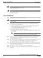
1.2.1 Perform a Facility Loopback on a Source-Node Port
The facility loopback test is performed on the node source port in the network circuit. Completing a
successful facility loopback on this port isolates the cabling and port as possible failure points.
Caution
Note
Performing a loopback on an in-service circuit is service-affecting.
Loopbacks operate only on ports in the Out-of-Service, Maintenance (OOS,MT) administrative state and
Out-of-Service and Management, Maintenance (OOS-MA,MT) service state. Brief instructions are
given in each procedure for changing the port’s state. For more information about port state, refer to the
Cisco ONS 15310-CL and Cisco ONS 15310-MA Procedure Guide.
Create the Facility Loopback on the Source-Node Port
Step 1
Connect an electrical test set to the DS-1, DS-3, or EC-1 port you are testing. For the ONS 15310-CL,
this port is located on the 15310-CL-CTX. For the ONS 15310-MA, this port is located on the
DS1-28/DS3-EC1-3 or DS1-84/DS3-EC1-3.
Use appropriate cabling to attach the transmit (Tx) and receive (Rx) terminals of the electrical test set to
the port.
Step 2
Adjust the test set accordingly.
Cisco ONS 15310-CL and Cisco ONS 15310-MA Troubleshooting Guide, R7.0
1-4
Chapter 1
General Troubleshooting
1.2.1 Perform a Facility Loopback on a Source-Node Port
Step 3
Use CTC to create the facility loopback on the port being tested:
a.
In node view, double-click the card where you are performing the loopback, then click the
appropriate tab:
•
Maintenance > DS1 > Loopback
•
Maintenance > DS3 > Loopback
•
Maintenance > EC1 > Loopback
b.
Choose OOS,MT from the Admin State column for the port being tested.
c.
Choose Facility from the Loopback Type column for the port being tested.
d.
Click Apply.
e.
Click Yes in the confirmation dialog box.
It is normal for a facility loopback 2.7.156 LPBKFACILITY (DS1, DS3) or
2.7.157 LPBKFACILITY (EC1) condition to appear during loopback setup. The condition
clears when you remove the loopback.
Note
Step 4
Continue with the “Test the Facility Loopback” procedure on page 1-5.
Test the Facility Loopback
Step 1
If the test set is not already sending traffic, send test-set traffic on the loopback circuit.
Step 2
Examine the traffic received by the test set. Look for errors or any other signal information that the test
set is capable of indicating.
Step 3
If the test set indicates a good circuit, complete the following steps:
a.
Step 4
Double-click the electrical card, then click the appropriate tab:
•
Maintenance > DS1 > Loopback
•
Maintenance > DS3 > Loopback
•
Maintenance > EC1 > Loopback
b.
Choose None from the Loopback Type column for the port being tested.
c.
Choose the appropriate state (IS,AINS; OOS,DSBLD; or OOS,MT) from the Admin State column
for the port being tested.
d.
Click Apply.
e.
Click Yes in the confirmation dialog box.
If the test set indicates a faulty circuit, the problem might be a faulty card, faulty port, or faulty cabling
from the electrical port. Continue with the “Test the Electrical Cabling” procedure on page 1-6.
Cisco ONS 15310-CL and Cisco ONS 15310-MA Troubleshooting Guide, R7.0
1-5
Chapter 1
General Troubleshooting
1.2.2 Perform a Hairpin on a Source-Node Port
Test the Electrical Cabling
Step 1
Replace the suspect cabling (the cables from the test set to the electrical port) with a cable known to be
good.
If a cable known to be good is not available, test the suspect cable with a test set. Remove the suspect
cable from the electrical port and connect the cable to the Tx and Rx terminals of the test set. Run traffic
to determine whether the cable is good or suspect.
Step 2
Resend test-set traffic on the loopback circuit with a good cable installed.
Step 3
If the test set indicates a good circuit, the problem is probably the defective cable. Replace the defective
cable, then clear the loopback:
a.
Step 4
Double-click the card, then click the appropriate tab:
•
Maintenance > DS1 > Loopback
•
Maintenance > DS3 > Loopback
•
Maintenance > EC1 > Loopback
b.
Choose None from the Loopback Type column for the port being tested.
c.
Choose the appropriate state (IS,AINS; OOS,DSBLD; or OOS,MT) from the Admin State column
for the port being tested.
d.
Click Apply.
e.
Click Yes in the confirmation dialog box.
If the test set indicates a faulty circuit, the problem might be a faulty port. Continue with the
“1.2.2 Perform a Hairpin on a Source-Node Port” procedure on page 1-6.
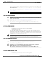
1.2.2 Perform a Hairpin on a Source-Node Port
The hairpin test is performed on the first port in the network circuit. A hairpin circuit uses the same port
for both source and destination. Completing a successful hairpin through this port isolates the possibility
that the source port is the cause of the faulty circuit.
Create the Hairpin on the Source-Node Port
Step 1
Connect an electrical test set to the port you are testing.
•
If you just completed the “1.2.1 Perform a Facility Loopback on a Source-Node Port” procedure on
page 1-4, leave the electrical test set connected to the electrical port.
•
If you are starting the current procedure without the electrical test set connected to the electrical
port, use appropriate cabling to attach the Tx and Rx terminals of the electrical test set to the
electrical connectors for the port you are testing.
Step 2
Adjust the test set accordingly.
Step 3
Use CTC to set up the hairpin on the port being tested:
a.
Click the Circuits tab and click Create.
b.
Give the circuit an easily identifiable name, such as Hairpin1.
Cisco ONS 15310-CL and Cisco ONS 15310-MA Troubleshooting Guide, R7.0
1-6
Chapter 1
General Troubleshooting
1.2.2 Perform a Hairpin on a Source-Node Port
c.
Set the circuit Type and Size to the normal preferences, such as STS and STS1.
d.
Uncheck the Bidirectional check box and click Next.
e.
In the Circuit Source dialog box, select the same Node, Slot, Port, and Type where the test set is
connected and click Next.
f.
In the Circuit Destination dialog box, use the same Node, Slot, Port, and Type used for the Circuit
Source dialog box and click Finish.
Step 4
Confirm that the newly created circuit appears on the Circuits tab list as a one-way circuit.
Step 5
Continue with the “Test the Hairpin Circuit” procedure on page 1-8.
Cisco ONS 15310-CL and Cisco ONS 15310-MA Troubleshooting Guide, R7.0
1-7
Chapter 1
General Troubleshooting
1.2.3 Perform a Terminal Loopback on a Destination-Node Port
Test the Hairpin Circuit
Step 1
If the test set is not already sending traffic, send test-set traffic on the loopback circuit.
Step 2
Examine the test traffic received by the test set. Look for errors or any other signal information that the
test set is capable of indicating.
Step 3
If the test set indicates a good circuit, no further testing is necessary with the hairpin loopback circuit.
Clear the hairpin circuit:
Step 4
a.
Click the Circuits tab.
b.
Choose the hairpin circuit being tested.
c.
Click Delete.
d.
Click Yes in the Delete Circuits dialog box.
e.
Confirm that the hairpin circuit is deleted from the Circuits tab list.
If the test set indicates a faulty circuit, there might be a problem with the port. Continue with the
“1.2.3 Perform a Terminal Loopback on a Destination-Node Port” procedure on page 1-8.
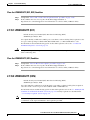
1.2.3 Perform a Terminal Loopback on a Destination-Node Port
The terminal loopback test is performed on the node destination port in the circuit. First, create a
bidirectional circuit that originates on the source node electrical port (such as DS-1, DS-3, or EC-1) and
terminates on the destination-node electrical port. Then continue with the terminal loopback test.
Completing a successful terminal loopback to a destination-node port verifies that the circuit is good up
to the destination port.
Caution
Performing a loopback on an in-service circuit is service-affecting.
Create the Terminal Loopback on a Destination-Node Port
Step 1
Connect an electrical test set to the port you are testing:
a.
If you just completed the “1.2.2 Perform a Hairpin on a Source-Node Port” procedure on page 1-6,
leave the electrical test set connected to the electrical port in the source node.
b.
If you are starting the current procedure without the electrical test set connected to the port, use
appropriate cabling to attach the Tx and Rx terminals of the electrical test set to the connectors for
the electrical port you are testing.
Step 2
Adjust the test set accordingly.
Step 3
Use CTC to set up the terminal loopback circuit on the port being tested:
a.
Click the Circuits tab and click Create.
b.
Give the circuit an easily identifiable name, such as DSNtoDSN.
c.
Set circuit Type and Size to the normal preferences, such as STS and STS1.
d.
Leave the Bidirectional check box checked and click Next.
Cisco ONS 15310-CL and Cisco ONS 15310-MA Troubleshooting Guide, R7.0
1-8
Chapter 1
General Troubleshooting
1.2.3 Perform a Terminal Loopback on a Destination-Node Port
Step 4
Step 5
e.
In the Circuit Source dialog box, fill in the source Node, Slot, Port, and Type where the test set is
connected and click Next.
f.
In the Circuit Destination dialog box, fill in the destination Node, Slot, Port, and Type (the electrical
port in the destination node) and click Finish.
Confirm that the newly created circuit appears on the Circuits tab list as a two-way circuit.
Note
Loopbacks operate only on ports in the OOS,MT administrative state.
Note
It is normal for a 2.7.160 LPBKTERMINAL (DS1, DS3) or 2.7.161 LPBKTERMINAL (EC1)
condition to appear during a loopback setup. The condition clears when you remove the
loopback.
Create the terminal loopback on the destination port being tested:
a.
Step 6
Go to the node view of the destination node:
•
From the View menu, choose Go To Other Node.
•
Choose the node from the drop-down list in the Select Node dialog box and click OK.
b.
In node view, double-click the destination node (ONS 15310-CL or ONS 15310-MA).
c.
Double-click the correct card, then click the appropriate following tabs:
•
Maintenance > DS1 > Loopback
•
Maintenance > DS3 > Loopback
•
Maintenance > EC1 > Loopback
d.
Select OOS,MT from the Admin State column.
e.
Select Terminal from the Loopback Type column.
f.
Click Apply.
g.
Click Yes in the confirmation dialog box.
Continue with the “Test the Terminal Loopback Circuit on the Destination-Node Port” procedure on
page 1-9.
Test the Terminal Loopback Circuit on the Destination-Node Port
Step 1
If the test set is not already sending traffic, send test-set traffic on the loopback circuit.
Step 2
Examine the test traffic being received by the test set. Look for errors or any other signal information
that the test set is capable of indicating.
Cisco ONS 15310-CL and Cisco ONS 15310-MA Troubleshooting Guide, R7.0
1-9
Chapter 1
General Troubleshooting
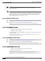
1.2.4 Perform a Hairpin Test on a Destination-Node Port
Step 3
Step 4
Step 5
If the test set indicates a good circuit, no further testing is necessary on the loopback circuit. Clear the
terminal loopback:
a.
Double-click the 15310-CL-CTX or CTX2500 in the destination node with the terminal loopback.
b.
Double-click the appropriate card containing the electrical circuit you are testing, and click the
appropriate tab:
•
Maintenance > DS1 > Loopback
•
Maintenance > DS3 > Loopback
•
Maintenance > EC1 > Loopback
c.
Select None from the Loopback Type column for the port being tested.
d.
Select the appropriate state (IS,AINS,AINS OOS,DSBLD or OOS,MT) in the Admin State column
for the port being tested.
e.
Click Apply.
f.
Click Yes in the confirmation dialog box.
Clear the terminal loopback circuit:
a.
Click the Circuits tab.
b.
Choose the loopback circuit being tested.
c.
Click Delete.
d.
Click Yes in the Delete Circuits dialog box.
If the test set indicates a faulty circuit, the problem might be a faulty port. Continue with the
“1.2.4 Perform a Hairpin Test on a Destination-Node Port” procedure on page 1-10.
1.2.4 Perform a Hairpin Test on a Destination-Node Port
The hairpin test is performed on the port in the destination node. To perform this test, you must also
create a bidirectional circuit in the transmit direction from the destination ONS 15310-CL or
ONS 15310-MA to the source node. Creating the bidirectional circuit and completing a successful
hairpin eliminates the possibility that the source port, destination port, or fiber span is responsible for
the faulty circuit.
Create the Hairpin Loopback Circuit on the Destination-Node Port
Step 1
Connect an electrical test set to the electrical port you are testing.
Use appropriate cabling to attach the Tx and Rx terminals of the electrical test set to the electrical cabling
panel for the port you are testing.
Step 2
Adjust the test set accordingly.
Step 3
Use CTC to set up the source loopback circuit on the port being tested:
a.
Click the Circuits tab and click Create.
b.
Give the circuit an easily identifiable name, such as Hairpin1.
c.
Set the circuit Type and Size to the normal preferences, such as STS and STS1.
d.
Leave the Bidirectional check box checked and click Next.
Cisco ONS 15310-CL and Cisco ONS 15310-MA Troubleshooting Guide, R7.0
1-10
Chapter 1
General Troubleshooting
1.2.4 Perform a Hairpin Test on a Destination-Node Port
e.
In the Circuit Source dialog box, fill in the source Node, Slot, Port, and Type where the test set is
connected and click Next.
f.
In the Circuit Destination dialog box, fill in the destination Node, Slot, Port, and Type (the port in
the destination node) and click Finish.
Step 4
Confirm that the newly created circuit appears on the Circuits tab list as a two-way circuit.
Step 5
Use CTC to set up the destination hairpin circuit on the port being tested.
The destination loopback circuit on a port is a one-way test.
Note
For example, in a typical east-to-west slot configuration, a DS-3 port on the source node is one end of
the fiber span, and a DS-3 port on the destination node is the other end.
a.
Click the Circuits tab and click Create.
b.
Give the circuit an easily identifiable name, such as Hairpin1.
c.
Set the Circuit Type and Size to the normal preferences, such as STS and STS1.
d.
Uncheck the Bidirectional check box and click Next.
e.
In the Circuit Source dialog box, select the same Node, Slot, Port, and Type where the previous
circuit is connected and click Next.
f.
In the Circuit Destination dialog box, use the same Node, Slot, Port, and Type used for the Circuit
Source dialog box and click Finish.
Step 6
Confirm that the newly created circuit appears on the Circuits tab list as a one-way circuit.
Step 7
Verify that the circuits connect to the correct slots. For example, verify that source node OC-N port (east
slot) is connected to the destination node (west slot). If two east slots or two west slots are connected,
the circuit does not work. Except for the distinct slots, all other circuit information, such as ports, should
be identical.
Step 8
Continue with the “Test the Hairpin Circuit” procedure on page 1-11.
Test the Hairpin Circuit
Step 1
If the test set is not already sending traffic, send test-set traffic on the loopback circuit.
Step 2
Examine the test traffic received by the test set. Look for errors or any other signal information indicated
by the test set.
Step 3
If the test set indicates a good circuit, no further testing is necessary; clear the hairpin circuit:
a.
Click the Circuits tab.
b.
Choose the hairpin circuit being tested.
c.
Click Delete.
d.
Click Yes in the Delete Circuits dialog box.
e.
Confirm that the hairpin circuit is deleted from the Circuits tab list.
f.
Continue with the “1.2.5 Perform a Facility Loopback on a Destination Port” procedure on
page 1-12.
Cisco ONS 15310-CL and Cisco ONS 15310-MA Troubleshooting Guide, R7.0
1-11
Chapter 1
General Troubleshooting
1.2.5 Perform a Facility Loopback on a Destination Port
1.2.5 Perform a Facility Loopback on a Destination Port
The final facility loopback test is performed on the last port in the circuit— in this case the port in the
destination node. Completing a successful facility loopback on this port isolates the possibility that the
destination-node cabling, card, or LIU is responsible for a faulty circuit.
Caution
Note
Performing a loopback on an in-service circuit is allowed but is service-affecting.
Loopbacks operate only on ports in the OOS,MT administrative state.
Create a Facility Loopback Circuit on a Destination Port
Step 1
Step 2
Connect an electrical test set to the port you are testing:
a.
If you just completed the “1.2.4 Perform a Hairpin Test on a Destination-Node Port” procedure on
page 1-10, leave the electrical test set connected to the electrical port in the destination node.
b.
If you are starting the current procedure without the electrical test set connected to the electrical
port, use appropriate cabling to attach the Tx and Rx terminals of the electrical test set to the
electrical interface panel.
c.
Adjust the test set accordingly.
Use CTC to create the facility loopback on the port being tested:
a.
•
Maintenance > DS1 > Loopback
•
Maintenance > DS3 > Loopback
•
Maintenance > EC1 > Loopback
b.
Select Facility from the Loopback Type column for the port being tested. If you are creating a
loopback on a multiport card, select the row appropriate for the desired port.
c.
Click Apply.
d.
Click Yes in the confirmation dialog box.
Note
Step 3
In node view, double-click the card where you are performing the loopback, then click the
appropriate tab:
It is normal for a 2.7.156 LPBKFACILITY (DS1, DS3) or 2.7.157 LPBKFACILITY (EC1)
condition to appear during loopback setup. The condition clears when you remove the loopback.
Continue with the “Test the Facility Loopback Circuit” procedure on page 1-13.
Cisco ONS 15310-CL and Cisco ONS 15310-MA Troubleshooting Guide, R7.0
1-12
Chapter 1
General Troubleshooting
1.2.5 Perform a Facility Loopback on a Destination Port
Test the Facility Loopback Circuit
Step 1
If the test set is not already sending traffic, send test-set traffic on the loopback circuit.
Step 2
Examine the test traffic received by the test set. Look for errors or any other signal information that the
test set is capable of indicating.
Step 3
If the test set indicates a good circuit, no further testing is necessary with the loopback circuit.
a.
Clear the facility loopback:
b.
Double-click the card, then click the appropriate tab:
•
Maintenance > DS1 > Loopback
•
Maintenance > DS3 > Loopback
•
Maintenance > EC1 > Loopback
c.
Choose None from the Loopback Type column for the port being tested.
d.
Choose the appropriate state (IS,AINS; OOS,DSBLD; or OOS,MT) from the Admin State column
for the port being tested.
e.
Click Apply.
f.
Click Yes in the confirmation dialog box.
The entire electrical circuit path has now passed its comprehensive series of loopback tests. This circuit
qualifies to carry live traffic.
Step 4
If the test set indicates a faulty circuit, the problem might be a faulty card or faulty cabling. Continue
with the “Test the Electrical Cabling” procedure on page 1-13.
Test the Electrical Cabling
Step 1
Replace the suspect cabling (the cables from the test set to the DS-1, DS-3, or EC-1 port) with a cable
known to be good.
If a cable known to be good is not available, test the suspect cable with a test set. Remove the suspect
cable from the electrical port and connect the cable to the Tx and Rx terminals of the test set. Run traffic
to determine whether the cable is good or suspect.
Step 2
Resend test traffic on the loopback circuit with a good cable installed.
Step 3
If the test set indicates a good circuit, the problem is probably the defective cable. Replace the defective
cable.
Step 4
Clear the facility loopback:
a.
Double-click the card and then click the appropriate tab:
•
Maintenance > DS1 > Loopback
•
Maintenance > DS3 > Loopback
•
Maintenance > EC1 > Loopback
b.
Choose None from the Loopback Type column for the port being tested.
c.
Choose the appropriate state (IS,AINS; OOS,DSBLD; or OOS,MT) from the Admin State column
for the port being tested.
Cisco ONS 15310-CL and Cisco ONS 15310-MA Troubleshooting Guide, R7.0
1-13
Chapter 1
General Troubleshooting
1.3 Identify Points of Failure on an OC-N Circuit Path
d.
Click Apply.
e.
Click Yes in the confirmation dialog box.
The entire DS-N circuit path has now passed its comprehensive series of loopback tests. This circuit
qualifies to carry live traffic.
1.3 Identify Points of Failure on an OC-N Circuit Path
Using facility loopbacks, terminal loopbacks, and cross-connect loopback circuits, you can test OC-N
facilities or STSs on the ONS 15310-CL or ONS 15310-MA to logically isolate faults. For this purpose,
you perform a loopback test at each point along the circuit path to systematically isolate a point of
failure.
The example in this section tests an OC-N circuit on a three-node path protection. Using a series of
facility loopbacks and terminal loopbacks, the path of the circuit is traced and the possible points of
failure are tested and eliminated. A logical progression of seven network test procedures applies to this
sample scenario:
1.
Facility loopback on the source-node OC-N port
2.
Cross-connect loopback on the source-node OC-N port
3.
Terminal loopback on the source-node OC-N port
4.
Facility loopback on the intermediate-node OC-N port
5.
Terminal loopback on the intermediate-node OC-N port
6.
Facility loopback on the destination-node OC-N port
7.
Terminal loopback on the destination-node OC-N port
Note
The test sequence for your circuits differs according to the type of circuit and network topology.
Note
Facility and terminal loopback tests require on-site personnel.
1.3.1 Perform a Facility Loopback on a Source-Node OC-N Port
The facility loopback test is performed on the node source port in the network circuit, in this example,
the source 15310-CL-CTX or CTX2500 OC-N port in the source node. Completing a successful facility
loopback on this port isolates the OC-N port as a possible failure point. Performing a loopback on an
in-service circuit is service-affecting.
Create the Facility Loopback on the Source OC-N Port
Step 1
Connect an optical test set to the port you are testing.
Use appropriate cabling to attach the Tx and Rx terminals of the optical test set to the port you are
testing.
Cisco ONS 15310-CL and Cisco ONS 15310-MA Troubleshooting Guide, R7.0
1-14
Chapter 1
General Troubleshooting
1.3.2 Perform a Cross-Connect Loopback on the Source OC-N Port
Step 2
Use CTC to create the facility loopback circuit on the port being tested:
a.
In node view, double-click the controller card (15310-CL-CTX or CTX2500) to display the card
view.
b.
Click the Maintenance > Optical > Loopback > Port tabs.
c.
Choose OOS,MT from the Admin State column for the port being tested.
d.
Choose Facility from the Loopback Type column for the port being tested.
e.
Click Apply.
f.
Click Yes in the confirmation dialog box.
Note
Step 3
It is normal for a 2.7.158 LPBKFACILITY (OCN) condition to appear during loopback
setup. The condition clears when you remove the loopback.
Continue with the “Test the Facility Loopback Circuit” procedure on page 1-15.
Test the Facility Loopback Circuit
Step 1
If the test set is not already sending traffic, send test traffic on the loopback circuit.
Step 2
Examine the traffic received by the test set. Look for errors or any other signal information that the test
set is capable of indicating.
Step 3
If the test set indicates a good circuit, no further testing is necessary with the facility loopback. Clear the
facility loopback:
g.
Click the Maintenance > Optical > Loopback > Port tabs.
h.
Choose None from the Loopback Type column for the port being tested.
i.
Choose the appropriate state (IS,AINS; OOS,DSBLD; or OOS,MT) from the Admin State column
for the port being tested.
j.
Click Apply.
k.
Click Yes in the confirmation dialog box.
l.
Continue with the “1.3.2 Perform a Cross-Connect Loopback on the Source OC-N Port” procedure
on page 1-15.
1.3.2 Perform a Cross-Connect Loopback on the Source OC-N Port
The cross-connect loopback test occurs on the cross-connect portion of the controller card
(15310-CL-CTX or CTX2500) in a network circuit. Completing a successful cross-connect loopback
through the card isolates the possibility that the cross-connect is the cause of the faulty circuit.
Cisco ONS 15310-CL and Cisco ONS 15310-MA Troubleshooting Guide, R7.0
1-15
Chapter 1
General Troubleshooting
1.3.2 Perform a Cross-Connect Loopback on the Source OC-N Port
Create the Cross-Connect Loopback on the Source OC-N Port
Step 1
Step 2
Step 3
Step 4
Connect an optical test set to the port you are testing:
a.
If you just completed the “1.3.1 Perform a Facility Loopback on a Source-Node OC-N Port”
procedure on page 1-14, leave the optical test set connected to the OC-N port in the source node.
b.
If you are starting the current procedure without the optical test set connected to the OC-N port, use
appropriate cabling to attach the Tx and Rx terminals of the optical test set to the port you are
testing.
c.
Adjust the test set accordingly.
Use CTC to put the circuit being tested out of service:
a.
In node view, click the Circuits tab.
b.
Click the circuit and then click Edit.
c.
In the Edit Circuit dialog box, click the State tab.
d.
Choose OOS-MT from the Target Circuit Admin State drop-down list.
e.
Click Apply.
f.
Click Yes in the confirmation dialog box.
Use CTC to set up the cross-connect loopback on the circuit being tested:
a.
In node view, double-click the 15310-CL-CTX or CTX2500 to open the card view.
b.
For the OC-N port, click the Maintenance > Optical > Loopback > SONET STS tabs.
c.
Click the check box in the XC Loopback column for the port being tested.
d.
Click Apply.
e.
Click Yes in the confirmation dialog box.
Continue with the “Test the Cross-Connect Loopback Circuit” procedure on page 1-16.
Test the Cross-Connect Loopback Circuit
Step 1
If the test set is not already sending traffic, send test traffic on the loopback circuit.
Step 2
Examine the test traffic received by the test set. Look for errors or any other signal information that the
test set is capable of indicating.
Step 3
If the test set indicates a good circuit, no further testing is necessary with the cross-connect. Clear the
cross-connect loopback:
a.
In card view, click the Maintenance > Optical > Loopback > SONET STS tabs.
b.
Uncheck the check box in the XC Loopback column for the circuit being tested.
c.
Click Apply.
d.
Click Yes in the confirmation dialog box.
Cisco ONS 15310-CL and Cisco ONS 15310-MA Troubleshooting Guide, R7.0
1-16
Chapter 1
General Troubleshooting
1.3.3 Perform a Terminal Loopback on a Source-Node OC-N Port
Step 4
If the test set indicates a faulty circuit, there might be a problem with the cross-connect portion of the
15310-CL-CTX or CTX2500. Complete the “1.3.3 Perform a Terminal Loopback on a Source-Node
OC-N Port” procedure on page 1-17.
1.3.3 Perform a Terminal Loopback on a Source-Node OC-N Port
The terminal loopback test is performed on the node destination port in the circuit, in this example, the
destination OC-N port in the source node. First, create a bidirectional circuit that starts on the node
source OC-N port and loops back on the node destination OC-N port. Then continue with the terminal
loopback test. Completing a successful terminal loopback to a node destination OC-N port verifies that
the circuit is good up to the destination OC-N. Performing a loopback on an in-service circuit is
service-affecting.
Create the Terminal Loopback on a Source Node OC-N Port
Step 1
Step 2
Step 3
Connect an optical test set to the port you are testing:
a.
If you just completed the “1.3.2 Perform a Cross-Connect Loopback on the Source OC-N Port”
procedure on page 1-15, leave the optical test set connected to the OC-N port in the source node.
b.
If you are starting the current procedure without the optical test set connected to the OC-N port, use
appropriate cabling to attach the Tx and Rx terminals of the optical test set to the port you are
testing.
c.
Adjust the test set accordingly.
Use CTC to set up the terminal loopback circuit on the port being tested:
a.
Click the Circuits tab and click Create.
b.
Give the circuit an easily identifiable name, such as OCN1toOCN2.
c.
Set circuit Type and Size to the normal preferences, such as STS and STS1.
d.
Verify that Bidirectional is checked.
e.
Click Next.
f.
In the Circuit Source dialog box, fill in the same Node, Slot, Port, and Type where the test set is
connected and click Next.
g.
In the Circuit Destination dialog box, fill in the destination Node, Slot, Port, and Type (the OC-N
port in the source node) and click Finish.
Confirm that the newly created circuit appears on the Circuits tab list as a two-way circuit.
Note
Step 4
It is normal for a 2.7.162 LPBKTERMINAL (OCN) condition to appear during a loopback
setup. The condition clears when you remove the loopback.
Create the terminal loopback on the destination port being tested:
a.
In node view, double-click the card that requires the loopback.
b.
Click the Maintenance > Optical > Loopback > Port tabs.
c.
Select OOS,MT from the Admin State column.
Cisco ONS 15310-CL and Cisco ONS 15310-MA Troubleshooting Guide, R7.0
1-17
Chapter 1
General Troubleshooting
1.3.4 Perform a Facility Loopback on an Intermediate-Node OC-N Port
Step 5
d.
Select Terminal from the Loopback Type column.
e.
Click Apply.
f.
Click Yes in the confirmation dialog box.
Continue with the “Test the Terminal Loopback Circuit” procedure on page 1-18.
Test the Terminal Loopback Circuit
Step 1
If the test set is not already sending traffic, send test traffic on the loopback circuit.
Step 2
Examine the test traffic being received by the test set. Look for errors or any other signal information
that the test set is capable of indicating.
If the test set indicates a good circuit, no further testing is necessary on the loopback circuit:
Step 3
Step 4
Step 5
Clear the terminal loopback:
a.
Double-click the card in the source node having the terminal loopback.
b.
Click the Maintenance > Optical > Loopback > Port tabs.
c.
Select None from the Loopback Type column for the port being tested.
d.
Select the appropriate state (IS,AINS; OOS,DSBLD; or OOS,MT) in the Admin State column for
the port being tested.
e.
Click Apply.
f.
Click Yes in the confirmation dialog box.
Clear the terminal loopback circuit:
a.
Click the Circuits tab.
b.
Choose the loopback circuit being tested.
c.
Click Delete.
d.
Click Yes in the Delete Circuits dialog box.
If the test set indicates a faulty circuit, the problem might be a faulty port. Continue with the
“1.3.4 Perform a Facility Loopback on an Intermediate-Node OC-N Port” procedure on page 1-18.
1.3.4 Perform a Facility Loopback on an Intermediate-Node OC-N Port
The facility loopback test is performed on the node source port in the network circuit, in this example,
the source OC-N port in the intermediate node. Completing a successful facility loopback on this port
isolates the OC-N port as a possible failure point.
Caution
Performing a loopback on an in-service circuit is service-affecting.
Cisco ONS 15310-CL and Cisco ONS 15310-MA Troubleshooting Guide, R7.0
1-18
Chapter 1
General Troubleshooting
1.3.4 Perform a Facility Loopback on an Intermediate-Node OC-N Port
Create the Facility Loopback on an Intermediate-Node OC-N Port
Step 1
Step 2
Step 3
Connect an optical test set to the port you are testing:
a.
If you just completed the “1.3.3 Perform a Terminal Loopback on a Source-Node OC-N Port”
procedure on page 1-17, leave the optical test set connected to the OC-N port in the source node.
b.
If you are starting the current procedure without the optical test set connected to the OC-N port, use
appropriate cabling to attach the Tx and Rx terminals of the optical test set to the port you are
testing.
c.
Adjust the test set accordingly.
Use CTC to set up the facility loopback circuit on the port being tested:
a.
Click the Circuits tab and click Create.
b.
Give the circuit an easily identifiable name, such as OCN1toOCN3.
c.
Set circuit Type and Size to the normal preferences, such as STS and STS1.
d.
Verify that Bidirectional is checked and click Next.
e.
In the Circuit Source dialog box, fill in the source Node, Slot, Port, and Type where the test set is
connected and click Next.
f.
In the Circuit Destination dialog box, fill in the destination Node, Slot, Port, and Type (the OC-N
port in the intermediate node) and click Finish.
Confirm that the newly created circuit appears on the Circuits tab list as a two-way circuit.
It is normal for a 2.7.158 LPBKFACILITY (OCN) condition to appear during a loopback setup.
The condition clears when you remove the loopback.
Note
Step 4
Create the facility loopback on the destination port being tested:
a.
Go to the node view of the intermediate node:
•
From the View menu, choose Go To Other Node.
•
Choose the node from the drop-down list in the Select Node dialog box and click OK.
b.
In node view, double-click the controller card (15310-CL-CTX or CTX2500) in the intermediate
node.
c.
Click the Maintenance > Optical > Loopback > Port tabs.
d.
Select OOS,MT from the Admin State column.
e.
Select Facility from the Loopback Type column.
f.
Click Apply.
g.
Click Yes in the confirmation dialog box.
Note
Step 5
It is normal for a 2.7.158 LPBKFACILITY (OCN) condition to appear during loopback
setup. The condition clears when you remove the loopback.
Continue with the “Test the Facility Loopback Circuit” procedure on page 1-20.
Cisco ONS 15310-CL and Cisco ONS 15310-MA Troubleshooting Guide, R7.0
1-19
Chapter 1
General Troubleshooting
1.3.5 Perform a Terminal Loopback on an Intermediate-Node OC-N Port
Test the Facility Loopback Circuit
Step 1
If the test set is not already sending traffic, send test traffic on the loopback circuit.
Step 2
Examine the traffic received by the test set. Look for errors or any other signal information that the test
set is capable of indicating.
If the test set indicates a good circuit, no further testing is necessary with the facility loopback:
Step 3
Step 4
Step 5
Clear the facility loopback:
a.
Click the Maintenance > Optical > Loopback > Port tabs.
b.
Choose None from the Loopback Type column for the port being tested.
c.
Choose the appropriate state (IS,AINS; OOS,DSBLD; or OOS,MT) from the Admin State column
for the port being tested.
d.
Click Apply.
e.
Click Yes in the confirmation dialog box.
Clear the facility loopback circuit:
a.
Click the Circuits tab.
b.
Choose the loopback circuit being tested.
c.
Click Delete.
d.
Click Yes in the Delete Circuits dialog box.
If the test set indicates a faulty circuit, the problem might be a faulty OC-N port. Continue with the
“1.3.5 Perform a Terminal Loopback on an Intermediate-Node OC-N Port” procedure on page 1-20.
1.3.5 Perform a Terminal Loopback on an Intermediate-Node OC-N Port
The terminal loopback test is performed on the node destination port in the circuit, in this example, the
destination OC-N port in the intermediate node. First, create a bidirectional circuit that starts on the node
source OC-N port and loops back on the node destination OC-N port. Then continue with the terminal
loopback test. Completing a successful terminal loopback to a node destination OC-N port verifies that
the circuit is good up to the destination OC-N port.
Caution
Performing a loopback on an in-service circuit is service-affecting.
Create the Terminal Loopback on an Intermediate-Node OC-N Port
Step 1
Connect an optical test set to the port you are testing:
a.
If you just completed the “1.3.4 Perform a Facility Loopback on an Intermediate-Node OC-N Port”
procedure on page 1-18, leave the optical test set connected to the OC-N port in the source node.
b.
If you are starting the current procedure without the optical test set connected to the OC-N port, use
appropriate cabling to attach the Tx and Rx terminals of the optical test set to the port you are
testing.
c.
Adjust the test set accordingly.
Cisco ONS 15310-CL and Cisco ONS 15310-MA Troubleshooting Guide, R7.0
1-20
Chapter 1
General Troubleshooting
1.3.5 Perform a Terminal Loopback on an Intermediate-Node OC-N Port
Step 2
Step 3
Use CTC to set up the terminal loopback circuit on the port being tested:
a.
Click the Circuits tab and click Create.
b.
Give the circuit an easily identifiable name, such as OCN1toOCN4.
c.
Set circuit Type and Size to the normal preferences, such as STS and STS1.
d.
Leave the Bidirectional check box checked and click Next.
e.
In the Circuit Source dialog box, fill in the source Node, Slot, Port, and Type where the test set is
connected and click Next.
f.
In the Circuit Destination dialog box, fill in the destination Node, Slot, Port, and Type (the OC-N
port in the intermediate node) and click Finish.
Confirm that the newly created circuit appears on the Circuits tab list as a two-way circuit.
It is normal for a 2.7.162 LPBKTERMINAL (OCN) condition to appear during a loopback
setup. The condition clears when you remove the loopback.
Note
Step 4
Create the terminal loopback on the destination port being tested:
a.
Step 5
Go to the node view of the intermediate node:
•
From the View menu, choose Go To Other Node.
•
Choose the node from the drop-down list in the Select Node dialog box and click OK.
b.
In node view, double-click the controller card (15310-CL-CTX or CTX2500) with the OC-N port
requiring a loopback.
c.
Click the Maintenance > Optical > Loopback > Port tabs.
d.
Select OOS,MT from the Admin State column.
e.
Select Terminal from the Loopback Type column.
f.
Click Apply.
g.
Click Yes in the confirmation dialog box.
Continue with the “Test the Terminal Loopback Circuit” procedure on page 1-21.
Test the Terminal Loopback Circuit
Step 1
If the test set is not already sending traffic, send test traffic on the loopback circuit.
Step 2
Examine the test traffic being received by the test set. Look for errors or any other signal information
that the test set is capable of indicating.
If the test set indicates a good circuit, no further testing is necessary on the loopback circuit.
Step 3
Clear the terminal loopback:
a.
Double-click the card with the loopback.
b.
Click the Maintenance > Optical > Loopback > Port tabs.
c.
Select None from the Loopback Type column for the port being tested.
d.
Select the appropriate state (IS,AINS; OOS,DSBLD; or OOS,MT) in the Admin State column for
the port being tested.
Cisco ONS 15310-CL and Cisco ONS 15310-MA Troubleshooting Guide, R7.0
1-21
Chapter 1
General Troubleshooting
1.3.6 Perform a Facility Loopback on a Destination-Node OC-N Port
Step 4
Step 5
e.
Click Apply.
f.
Click Yes in the confirmation dialog box.
Clear the terminal loopback circuit:
a.
Click the Circuits tab.
b.
Choose the loopback circuit being tested.
c.
Click Delete.
d.
Click Yes in the Delete Circuits dialog box.
If the test set indicates a faulty circuit, the problem might be a faulty controller card (15310-CL-CTX or
CTX2500). Continue with the “1.3.6 Perform a Facility Loopback on a Destination-Node OC-N Port”
procedure on page 1-22.
1.3.6 Perform a Facility Loopback on a Destination-Node OC-N Port
The final facility loopback test is performed on the source OC-N port in the destination node.
Completing a successful facility loopback on this port isolates the OC-N port as a possible failure point.
Caution
Performing a loopback on an in-service circuit is service-affecting.
Create the Facility Loopback on a Destination-Node OC-N Port
Step 1
Step 2
Step 3
Connect an optical test set to the port you are testing:
a.
If you just completed the “1.3.5 Perform a Terminal Loopback on an Intermediate-Node OC-N
Port” procedure on page 1-20, leave the optical test set connected to the OC-N port in the source
node.
b.
If you are starting the current procedure without the optical test set connected to the OC-N port, use
appropriate cabling to attach the Tx and Rx terminals of the optical test set to the port you are
testing.
c.
Adjust the test set accordingly.
Use CTC to set up the facility loopback circuit on the port being tested:
a.
Click the Circuits tab and click Create.
b.
Give the circuit an easily identifiable name, such as OCN1toOCN5.
c.
Set circuit Type and Size to the normal preferences, such as STS and STS1.
d.
Leave the Bidirectional check box checked and click Next.
e.
In the Circuit Source dialog box, fill in the source Node, Slot, Port, and Type where the test set is
connected and click Next.
f.
In the Circuit Destination dialog box, fill in the destination Node, Slot, Port, and Type (the OC-N
port in the destination node) and click Finish.
Confirm that the newly created circuit appears on the Circuits tab list as a two-way circuit.
Cisco ONS 15310-CL and Cisco ONS 15310-MA Troubleshooting Guide, R7.0
1-22
Chapter 1
General Troubleshooting
1.3.6 Perform a Facility Loopback on a Destination-Node OC-N Port
It is normal for a 2.7.158 LPBKFACILITY (OCN) condition to appear during a loopback setup.
The condition clears when you remove the loopback.
Note
Step 4
Create the facility loopback on the destination port being tested:
a.
Go to the node view of the destination node:
•
From the View menu, choose Go To Other Node.
•
Choose the node from the drop-down list in the Select Node dialog box and click OK.
b.
In node view, double-click the 15310-CL-CTX or CTX2500 with the OC-N port that requires the
loopback.
c.
Click the Maintenance > Optical > Loopback > Port tabs.
d.
Select OOS,MT from the Admin State column.
e.
Select Terminal from the Loopback Type column.
f.
Click Apply.
g.
Click Yes in the confirmation dialog box.
Note
Step 5
It is normal for a 2.7.158 LPBKFACILITY (OCN) condition to appear during loopback
setup. The condition clears when you remove the loopback.
Continue with the “Test the Facility Loopback Circuit” procedure on page 1-23.
Test the Facility Loopback Circuit
Step 1
If the test set is not already sending traffic, send test traffic on the loopback circuit.
Step 2
Examine the traffic received by the test set. Look for errors or any other signal information that the test
set is capable of indicating.
If the test set indicates a good circuit, no further testing is necessary with the facility loopback:
Step 3
Step 4
Clear the facility loopback:
a.
Click the Maintenance > Optical > Loopback > Port tabs.
b.
Choose None from the Loopback Type column for the port being tested.
c.
Choose the appropriate state (IS,AINS; OOS,DSBLD; or OOS,MT) from the Admin State column
for the port being tested.
d.
Click Apply.
e.
Click Yes in the confirmation dialog box.
Clear the facility loopback circuit:
a.
Click the Circuits tab.
b.
Choose the loopback circuit being tested.
c.
Click Delete.
d.
Click Yes in the Delete Circuits dialog box.
Cisco ONS 15310-CL and Cisco ONS 15310-MA Troubleshooting Guide, R7.0
1-23
Chapter 1
General Troubleshooting
1.3.7 Perform a Terminal Loopback on a Destination-Node OC-N Port
Step 5
If the test set indicates a faulty circuit, the problem might be a faulty OC-N port. Continue with the
“1.3.7 Perform a Terminal Loopback on a Destination-Node OC-N Port” procedure on page 1-24.
1.3.7 Perform a Terminal Loopback on a Destination-Node OC-N Port
The terminal loopback test is performed on the destination OC-N port in the destination node. First,
create a bidirectional circuit that starts on the node source OC-N port and loops back on the node
destination OC-N port. Then continue with the terminal loopback test. Completing a successful terminal
loopback to a node destination OC-N port verifies that the circuit is good up to the destination OC-N.
Caution
Performing a loopback on an in-service circuit is service-affecting.
Create the Terminal Loopback on a Destination-Node OC-N Port
Step 1
Step 2
Step 3
Connect an optical test set to the port you are testing:
a.
If you just completed the “1.3.6 Perform a Facility Loopback on a Destination-Node OC-N Port”
procedure on page 1-22, leave the optical test set connected to the OC-N port in the source node.
b.
If you are starting the current procedure without the optical test set connected to the OC-N port, use
appropriate cabling to attach the Tx and Rx terminals of the optical test set to the port you are
testing.
c.
Adjust the test set accordingly.
Use CTC to set up the terminal loopback circuit on the port being tested:
a.
Click the Circuits tab and click Create.
b.
Give the circuit an easily identifiable name, such as OCN1toOCN6.
c.
Set circuit Type and Size to the normal preferences, such as STS and STS1.
d.
Leave the Bidirectional check box checked and click Next.
e.
In the Circuit Source dialog box, fill in the source Node, Slot, Port, and Type where the test set is
connected and click Next.
f.
In the Circuit Destination dialog box, fill in the destination Node, Slot, Port, and Type (the OC-N
port in the destination node) and click Finish.
Confirm that the newly created circuit appears on the Circuits tab list as a two-way circuit.
It is normal for a 2.7.162 LPBKTERMINAL (OCN) condition to appear during a loopback
setup. The condition clears when you remove the loopback.
Note
Step 4
Create the terminal loopback on the destination port being tested:
a.
Go to the node view of the destination node:
•
From the View menu, choose Go To Other Node.
•
Choose the node from the drop-down list in the Select Node dialog box and click OK.
Cisco ONS 15310-CL and Cisco ONS 15310-MA Troubleshooting Guide, R7.0
1-24
Chapter 1
General Troubleshooting
1.4 Troubleshooting Wideband Electrical Card(WBE-28 and WBE-84 Cards) FEAC on DS3 Ports
Step 5
b.
In node view, double-click the controller card (15310-CL-CTX or CTX2500) with the OC-N port
that requires the loopback, such as the 15310-CL-CTX in the destination-node ONS 15310-CL.
c.
Click the Maintenance > Optical > Loopback > Port tabs.
d.
Select OOS,MT from the Admin State column.
e.
Select Terminal from the Loopback Type column.
f.
Click Apply.
g.
Click Yes in the confirmation dialog box.
Continue with the “Test the Terminal Loopback Circuit” procedure on page 1-25.
Test the Terminal Loopback Circuit
Step 1
If the test set is not already sending traffic, send test traffic on the loopback circuit.
Step 2
Examine the test traffic being received by the test set. Look for errors or any other signal information
that the test set is capable of indicating.
Step 3
If the test set indicates a good circuit, no further testing is necessary on the loopback circuit:
a.
b.
Clear the terminal loopback:
•
Double-click the card terminal node with the terminal loopback.
•
Click the Maintenance > Optical > Loopback > Port tabs.
•
Select None from the Loopback Type column for the port being tested.
•
Select the appropriate state (IS,AINS; OOS,DSBLD; or OOS,MT) in the Admin State column
for the port being tested.
•
Click Apply.
•
Click Yes in the confirmation dialog box.
Clear the terminal loopback circuit:
•
Click the Circuits tab.
•
Choose the loopback circuit being tested.
•
Click Delete.
•
Click Yes in the Delete Circuits dialog box.
If no fault is found, the entire OC-N circuit path has now passed its comprehensive series of loopback
tests. This circuit qualifies to carry live traffic.
1.4 Troubleshooting Wideband Electrical Card(WBE-28 and
WBE-84 Cards) FEAC on DS3 Ports
WBE-28/WBE-84 cards support far-end alarm and control(FEAC) functions on DS3 ports. Click the
WBE-28/WBE-84 Maintenance > DS3 tabs at the card view to reveal the two additional function
columns. Figure 1-1 shows the DS3 subtab and the additional Send Code and Inhibit FE Lbk function
columns.
Cisco ONS 15310-CL and Cisco ONS 15310-MA Troubleshooting Guide, R7.0
1-25
Chapter 1
General Troubleshooting
1.4.1 FEAC Send Code
Figure 1-1
Accessing FEAC Functions on the DS3 ports of WBE-28/WBE-84 Cards
The "far end" in FEAC refers to the equipment connected to the WBE card and not to the far end of a
circuit. In Figure 1-2, if a WBE-28/WBE-84 DS3 (near-end) port is configured to send a line loop code,
the code will be sent to the connected test set, not the WBE-28/WBE-84 DS3 (far-end) port. FEAC
functions will be available only when the DS3 port is configured in CBIT Framing.
Diagram of FEAC Circuit
Node A
Tx
Rx
Node B
Tx
Rx
Test Set
WBE
(Near End)
Rx
Tx
Tx
Rx
OC48
WBE
(Far End)
OC48
Ring
OC48
CPE
240421
Figure 1-2
1.4.1 FEAC Send Code
The Send Code column on the WBE-28/WBE-84 cards Maintenance tab only applies to OOS-MA,MT
ports configured for CBIT framing. The column lets a user select No Code (the default) or line loop code.
Selecting line loop code inserts a line loop activate FEAC in the CBIT overhead transmitting to the
connected facility. This code initiates a loopback from the facility to the ONS 15310-MA. Selecting No
Code sends a line-loop-deactivate FEAC code to the connected equipment, which will remove the
loopback.
Cisco ONS 15310-CL and Cisco ONS 15310-MA Troubleshooting Guide, R7.0
1-26
Chapter 1
General Troubleshooting
1.4.2 WBE-28/WBE-84 Inhibit FEAC Loopback
1.4.2 WBE-28/WBE-84 Inhibit FEAC Loopback
WBE-28/WBE-84 DS3 ports initiate loopbacks when they receive FEAC line loop codes. If the Inhibit
FE Lbk check box is checked for a DS3 port, that port ignores any FEAC line loop codes it receives and
will not loop back (return them). If you inhibit a DS3 port's far end loopback response, this DS3 port is
not restricted from terminal or facility loopbacks.
1.4.3 FEAC Alarms
When an ONS 15310MA - WBE-28/WBE-84 DS3 port receives an activation code for a FEAC loopback,
it raises the “Clear the LPBKDS3FEAC Condition” condition on page 2-101. The condition clears when
the port receives the command to deactivate the FEAC loopback. If a node sends a FEAC loopback
command to the far end, the sending node raises a “LPBKDS3FEAC-CMD” condition on page 2-101 for
the near-end port.
1.5 Troubleshooting WBE-28 and WBE-84 Cards with Far End
Loopcodes on DS1 Ports
WBE Cards support Far End Loopcodes when the DS1 port is operating in ESF Framing mode. Click
the WBE-28/WBE-84 Maintenance->DS1 tab to reveal additional columns, namely , "Inhibit FE Lbk"
and "Send Code". Here we are using the term FE Loopcodes instead of FEAC in DS1, since DS1 supports
only Far End Loopcodes, but NOT Alarms.
Figure 1-3
Accessing Far End troubleshooting Functions on the WBE Cards
Cisco ONS 15310-CL and Cisco ONS 15310-MA Troubleshooting Guide, R7.0
1-27
Chapter 1
General Troubleshooting
1.5.1 FEAC Send Code
Note
The term "Far End" refers to the equipment connected to the WBE card and not to the far end of a circuit.
1.5.1 FEAC Send Code
The Send Code column on the WBE-28/WBE-84 card Maintenance tab only applies to OOS-MA,MT
ports configured for ESF framing. The column lets a user select No Code (the default) or line loop code.
Selecting line loop code inserts a line loop activate Far End Loopcode in the ESF overhead transmitting
to the connected facility. This code initiates a loopback from the facility to the ONS 15454. Selecting
No Code sends a line-loop-deactivate Far End Loopcode to the connected equipment, which will remove
the loopback.
1.5.2 WBE-28/WBE-84 Inhibit FEAC Loopback
WBE-28/WBE-84 DS1 ports initiate loopbacks when they receive Far End line loop codes. If the Inhibit
FE Lbk check box is checked for a DS1 port, that port ignores any Far End line loop codes it receives
and will not loop back. If you inhibit a DS1 port's far end loopback response, this DS1 port is not
restricted from terminal or facility loopbacks.
1.6 Troubleshooting Ethernet Circuit Paths With Loopbacks
Facility loopbacks, terminal loopbacks, and cross-connect loopback circuits are often used together to
test the circuit path through the network or to logically isolate a fault. Performing a loopback test at each
point along the circuit path systematically isolates possible points of failure.
When performing this testing on networks that contain intermediate nodes, you will test the OC-N
connection at intermediate nodes rather than CE100T-8 card connections. (The CE100T-8 is a mapper
card and is only capable of supporting point-to-point circuits.)
You can use these procedures on CE100T-8 cards but not on ML-100T-8 Ethernet cards. Using a series
of facility loopbacks and terminal loopbacks, the example scenario traces the circuit path, tests the
possible failure points, and eliminates them. The logical progression contains six network test
procedures:
Note
Note
The test sequence for your circuits will differ according to the type of circuit and network topology.
1.
A facility loopback on the source-node Ethernet port
2.
A terminal loopback on the source-node Ethernet port
3.
A facility loopback on the intermediate-node OC-N port
4.
A terminal loopback on the intermediate-node OC-N port
5.
A facility loopback on the destination-node Ethernet port
6.
A terminal loopback on the destination-node Ethernet port
Facility and terminal loopback tests require on-site personnel.
Cisco ONS 15310-CL and Cisco ONS 15310-MA Troubleshooting Guide, R7.0
1-28
Chapter 1
General Troubleshooting
1.6.1 Perform a Facility Loopback on a Source-Node Ethernet Port
1.6.1 Perform a Facility Loopback on a Source-Node Ethernet Port
The facility loopback test is performed on the node source port in the network circuit. Completing a
successful facility loopback on this port isolates the port as a possible failure point.
Note
Caution
Facility loopbacks require on-site personnel.
Performing a loopback on an in-service circuit is service-affecting.
Complete the “Create the Facility Loopback on the Source-Node Ethernet Port” procedure on page 1-29.
Create the Facility Loopback on the Source-Node Ethernet Port
Step 1
Connect a test set to the port you are testing.
Note
For specific procedures to connect, set up, and use the test set equipment, consult the
manufacturer.
Use appropriate cabling to attach the Tx and Rx terminals of the test set to the port you are testing. The
Tx and Rx terminals connect to the same port.
Step 2
Adjust the test set accordingly. (Refer to manufacturer instructions for test-set use.)
Step 3
In CTC node view, double-click the CE100T-8 card to display the card view.
Step 4
Click the Maintenance > Loopback tabs.
Step 5
Choose OOS,MT from the Admin State column for the port being tested. If this is a multiport card,
select the appropriate row for the desired port.
Step 6
Choose Facility from the Loopback Type column for the port being tested. If this is a multiport card,
select the appropriate row for the desired port.
Step 7
Click Apply.
Step 8
Click Yes in the confirmation dialog box.
Note
Step 9
It is normal for the “LPKTERMINAL (CE100T)” condition on page 2-104 to appear during
loopback setup. The condition clears when you remove the loopback.
Complete the “Test and Clear the Facility Loopback Circuit” procedure on page 1-29.
Test and Clear the Facility Loopback Circuit
Step 1
If the test set is not already sending traffic, send test traffic on the loopback circuit.
Step 2
Examine the traffic received by the test set. Look for errors or any other signal information that the test
set is capable of indicating.
Cisco ONS 15310-CL and Cisco ONS 15310-MA Troubleshooting Guide, R7.0
1-29
Chapter 1
General Troubleshooting
1.6.1 Perform a Facility Loopback on a Source-Node Ethernet Port
Step 3
Step 4
If the test set indicates a good circuit, no further testing is necessary with the facility loopback. Clear the
facility loopback:
a.
Double-click the CE100T-8 card, then click the Maintenance > Loopback tabs.
b.
Choose None from the Loopback Type column for the port being tested.
c.
Choose the appropriate state (IS; OOS,DSBLD; OOS,MT) from the Admin State column for the port
being tested.
d.
Click Apply.
e.
Click Yes in the confirmation dialog box.
Complete the “Test the Ethernet Card” procedure on page 1-30.
Test the Ethernet Card
Step 1
Caution
Complete the “Physically Replace a Card” procedure on page 2-154 for the suspected bad card and
replace it with a known-good one.
Removing a card that currently carries traffic on one or more ports can cause a traffic hit. To avoid this,
perform an external switch if a switch has not already occurred. Refer to the procedures in the
“2.10.1 Protection Switching, Lock Initiation, and Clearing” section on page 2-147. For more
information, refer to the “Maintain the Node” chapter in the Cisco ONS 15310-CL and
Cisco ONS 15310-MA Procedure Guide.
Step 2
Resend test traffic on the loopback circuit with a known-good card installed.
Step 3
If the test set indicates a good circuit, the problem was probably the defective card. Return the defective
card to Cisco through the Return Materials Authorization (RMA) process. Contact Cisco Technical
Support (1 800 553-2447).
Step 4
Complete the “Physically Replace a Card” procedure on page 2-154 for the faulty card.
Step 5
Clear the facility loopback:
Step 6
a.
Double-click the CE100T-8 card, then click the Maintenance > Loopback tabs.
b.
Choose None from the Loopback Type column for the port being tested.
c.
Choose the appropriate state (IS; OOS,DSBLD; OOS,MT) from the Admin State column for the port
being tested.
d.
Click Apply.
e.
Click Yes in the confirmation dialog box.
Complete the “1.6.2 Perform a Terminal Loopback on a Source-Node Ethernet Port” procedure on
page 1-31.
Cisco ONS 15310-CL and Cisco ONS 15310-MA Troubleshooting Guide, R7.0
1-30
Chapter 1
General Troubleshooting
1.6.2 Perform a Terminal Loopback on a Source-Node Ethernet Port
1.6.2 Perform a Terminal Loopback on a Source-Node Ethernet Port
The terminal loopback test is performed on the node source Ethernet port. To do this, you create a
bidirectional circuit that starts on the node destination CE100T-8 port and loops back on node source
CE100T-8 port. You then proceed with the terminal loopback test. Completing a successful terminal
loopback to a node source port verifies that the circuit is good to the source port.
Note
Caution
Terminal loopbacks require on-site personnel.
Performing a loopback on an in-service circuit is service-affecting.
Complete the “Create the Terminal Loopback on a Source-Node Ethernet Port” procedure on page 1-31.
Create the Terminal Loopback on a Source-Node Ethernet Port
Step 1
Connect a test set to the port you are testing:
Note
For specific procedures to connect, set up, and use the test set equipment, consult the
manufacturer.
a.
If you just completed the “1.6.1 Perform a Facility Loopback on a Source-Node Ethernet Port”
procedure on page 1-29, leave the test set hooked up to the Ethernet port in the source node.
b.
If you are starting the current procedure without the test set hooked up to the source port, use
appropriate cabling to attach the Tx and Rx terminals of the test set to the port you are testing. Both
Tx and Rx connect to the same port.
Step 2
Adjust the test set accordingly. (Refer to manufacturer instructions for test-set use.)
Step 3
Use CTC to set up the terminal loopback on the test port:
a.
In node view, click the Circuits tab and click Create.
b.
In the Circuit Creation dialog box, choose the type, such as STS, and number, such as 1.
c.
Click Next.
d.
In the next Circuit Creation dialog box, give the circuit an easily identifiable name such as
C1C1toC1C2.
e.
Leave the Bidirectional check box checked.
f.
Click Next.
g.
In the Circuit Creation source dialog box, select the same Node, card Slot, Port, and STS (or VT)
where the test set is connected.
h.
Click Next.
i.
In the Circuit Creation destination dialog box, use the same Node, card Slot, Port, and STS (or VT)
used for the source dialog box.
j.
Click Next.
k.
In the Circuit Creation circuit routing preferences dialog box, leave all defaults. Click Finish.
Cisco ONS 15310-CL and Cisco ONS 15310-MA Troubleshooting Guide, R7.0
1-31
Chapter 1
General Troubleshooting
1.6.2 Perform a Terminal Loopback on a Source-Node Ethernet Port
Step 4
Confirm that the newly created circuit appears on the Circuits tab list as a two-way circuit.
Note
Step 5
Step 6
It is normal for the “LPKTERMINAL (CE100T)” condition on page 2-104 to appear during a
loopback setup. The condition clears when you remove the loopback.
Create the terminal loopback on the destination port being tested:
a.
In node view, double-click the card that requires the loopback, such as the destination G-Series card
in the source node.
b.
Click the Maintenance > Loopback tabs.
c.
Select OOS,MT from the Admin State column. If this is a multiport card, select the row appropriate
for the desired port.
d.
Select Terminal from the Loopback Type column. If this is a multiport card, select the row
appropriate for the desired port.
e.
Click Apply.
f.
Click Yes in the confirmation dialog box.
Complete the “Test and Clear the Ethernet Terminal Loopback Circuit” procedure on page 1-32.
Test and Clear the Ethernet Terminal Loopback Circuit
Step 1
If the test set is not already sending traffic, send test traffic on the loopback circuit.
Step 2
Examine the test traffic being received by the test set. Look for errors or any other signal information
that the test set is capable of indicating.
Step 3
If the test set indicates a good circuit, no further testing is necessary on the loopback circuit. Clear the
terminal loopback state on the port:
Step 4
Step 5
a.
Double-click the CE100T-8 card in the source node with the terminal loopback.
b.
Click the Maintenance > Loopback tabs.
c.
Select None from the Loopback Type column for the port being tested.
d.
Select the appropriate state (IS; OOS,DSBLD; OOS,MT) in the Admin State column for the port
being tested.
e.
Click Apply.
f.
Click Yes in the confirmation dialog box.
Clear the terminal loopback circuit:
a.
Click the Circuits tab.
b.
Choose the loopback circuit being tested.
c.
Click Delete.
d.
Click Yes in the Delete Circuits dialog box. Do not check any check boxes.
Complete the “Test the Ethernet Card” procedure on page 1-33.
Cisco ONS 15310-CL and Cisco ONS 15310-MA Troubleshooting Guide, R7.0
1-32
Chapter 1
General Troubleshooting
1.6.3 Perform a Facility Loopback on an Intermediate-Node OC-N Port
Test the Ethernet Card
Step 1
Caution
Complete the “Physically Replace a Card” procedure on page 2-154 for the suspected bad card and
replace it with a known-good one.
Removing a card that currently carries traffic on one or more ports can cause a traffic hit. To avoid this,
perform an external switch if a switch has not already occurred. Refer to the procedures in the
“2.10.1 Protection Switching, Lock Initiation, and Clearing” section on page 2-147. For more
information, refer to the “Maintain the Node” chapter in the Cisco ONS 15310-CL and
Cisco ONS 15310-MA Procedure Guide.
Step 2
Resend test traffic on the loopback circuit with a known-good card.
Step 3
If the test set indicates a good circuit, the problem was probably the defective card. Return the defective
card to Cisco through the RMA process. Contact Cisco Technical Support (1 800 553-2447).
Step 4
Complete the “Physically Replace a Card” procedure on page 2-154 for the defective card.
Step 5
Clear the terminal loopback on the port before testing the next segment of the network circuit path:
Step 6
Step 7
a.
Double-click the CE100T-8 card with the terminal loopback in the source node.
b.
Click the Maintenance > Loopback tabs.
c.
Select None from the Loopback Type column for the port being tested.
d.
Select the appropriate state (IS; OOS,DSBLD; OOS,MT) in the Admin State column for the port
being tested.
e.
Click Apply.
f.
Click Yes in the confirmation dialog box.
Clear the terminal loopback circuit before testing the next segment of the network circuit path:
a.
Click the Circuits tab.
b.
Choose the loopback circuit being tested.
c.
Click Delete.
d.
Click Yes in the Delete Circuits dialog box. Do not check any check boxes.
Complete the “1.6.3 Perform a Facility Loopback on an Intermediate-Node OC-N Port” procedure on
page 1-33.
1.6.3 Perform a Facility Loopback on an Intermediate-Node OC-N Port
Performing the facility loopback test on an intermediate node OC-N port (which carries the Ethernet
circuit) isolates whether this node is causing circuit failure. Complete the “Create a Facility Loopback
on an Intermediate-Node OC-N Port” procedure on page 1-34.
Note
The CE100T-8 Ethernet card only supports point-to-point configurations and is not directly implicated
in the intermediate node testing.
Cisco ONS 15310-CL and Cisco ONS 15310-MA Troubleshooting Guide, R7.0
1-33
Chapter 1
General Troubleshooting
1.6.3 Perform a Facility Loopback on an Intermediate-Node OC-N Port
Create a Facility Loopback on an Intermediate-Node OC-N Port
Step 1
Connect a test set to the OC-N port you are testing. If you are starting the current procedure without the
test set hooked up to the source port, use appropriate cabling to attach the Tx and Rx terminals of the
test set to the port you are testing. Both Tx and Rx connect to the same port.
For specific procedures to connect, set up, and use the test set equipment, consult the
manufacturer.
Note
Step 2
Adjust the test set accordingly. (Refer to manufacturer instructions for test-set use.)
Step 3
Use CTC to set up the facility loopback on the OC-N port:
a.
In node view, click the Circuits tab and click Create.
b.
In the Circuit Creation dialog box, choose the type, such as STS, and number, such as 1.
c.
Click Next.
d.
In the next Circuit Creation dialog box, give the circuit an easily identifiable name such as
C1CtoC1C3.
e.
Leave the Bidirectional check box checked.
f.
Click Next.
g.
In the Circuit Creation source dialog box, select the same Node, card Slot, Port, and STS (or VT)
where the test set is connected.
h.
Click Next.
i.
In the Circuit Creation destination dialog box, use the same Node, card Slot, Port, and STS (or VT)
used for the source dialog box.
j.
Click Next.
k.
In the Circuit Creation circuit routing preferences dialog box, leave all defaults. Click Finish.
Step 4
Confirm that the newly created circuit appears on the Circuits tab list as a two-way circuit.
Step 5
Create the facility loopback on the destination port being tested:
a.
Go to the node view of the intermediate node:
•
Choose View > Go To Other Node from the menu bar.
•
Choose the node from the drop-down list in the Select Node dialog box and click OK.
b.
In node view, double-click the intermediate-node 15310-CL-CTX or CTX2500 card where you will
perform the loopback.
c.
Click the Maintenance > Optical > Loopback > Port tabs.
d.
Select OOS,MT from the Admin State column. If this is a multiport card, select the row appropriate
for the desired port.
e.
Select Facility from the Loopback Type column. If this is a multiport card, select the row
appropriate for the desired port.
f.
Click Apply.
g.
Click Yes in the confirmation dialog box.
Cisco ONS 15310-CL and Cisco ONS 15310-MA Troubleshooting Guide, R7.0
1-34
Chapter 1
General Troubleshooting
1.6.3 Perform a Facility Loopback on an Intermediate-Node OC-N Port
Note
Step 6
It is normal for the “LPBKFACILITY (OCN)” condition on page 2-103. The condition
clears when you remove the loopback.
Complete the “Test and Clear the OC-N Facility Loopback Circuit” procedure on page 1-35.
Test and Clear the OC-N Facility Loopback Circuit
Step 1
If the test set is not already sending traffic, send test traffic on the loopback circuit.
Step 2
Examine the traffic received by the test set. Look for errors or any other signal information that the test
set is capable of indicating.
Step 3
If the test set indicates a good circuit, no further testing is necessary with the facility loopback. Clear the
facility loopback from the port:
Step 4
Step 5
a.
Double-click the 15310-CL-CTX or CTX2500 card and click the Maintenance > Optical >
Loopback > Port tabs.
b.
Choose None from the Loopback Type column for the port being tested.
c.
Choose the appropriate state (IS; OOS,DSBLD; OOS,MT) from the Admin State column for the port
being tested.
d.
Click Apply.
e.
Click Yes in the confirmation dialog box.
Clear the facility loopback circuit:
a.
Click the Circuits tab.
b.
Choose the loopback circuit being tested.
c.
Click Delete.
d.
Click Yes in the Delete Circuits dialog box. Do not check any check boxes.
Complete the “Test the OC-N (Controller) Card” procedure on page 1-35.
Test the OC-N (Controller) Card
Step 1
Caution
Step 2
Complete the “Physically Replace a Card” procedure on page 2-154 for the suspected bad card and
replace it with a known-good one.
Removing a card that currently carries traffic on one or more ports can cause a traffic hit. To avoid this,
perform an external switch if a switch has not already occurred. Refer to the procedures in the
“2.10.1 Protection Switching, Lock Initiation, and Clearing” section on page 2-147. For more
information, refer to the “Maintain the Node” chapter in the Cisco ONS 15310-CL and
Cisco ONS 15310-MA Procedure Guide.
Resend test traffic on the loopback circuit with a known-good card installed.
Cisco ONS 15310-CL and Cisco ONS 15310-MA Troubleshooting Guide, R7.0
1-35
Chapter 1
General Troubleshooting
1.6.4 Perform a Terminal Loopback on Intermediate-Node OC-N Ports
Step 3
If the test set indicates a good circuit, the problem was probably the defective card. Return the defective
card to Cisco through the RMA process. Contact Cisco Technical Support (1 800 553-2447).
Step 4
Complete the “Physically Replace a Card” procedure on page 2-154 for the faulty card.
Step 5
Clear the facility loopback from the port:
Step 6
Step 7
a.
Double-click the card and click the Maintenance > Optical > Loopback > Port tabs.
b.
Choose None from the Loopback Type column for the port being tested.
c.
Choose the appropriate state (IS; OOS,DSBLD; OOS,MT) from the Admin State column for the port
being tested.
d.
Click Apply.
e.
Click Yes in the confirmation dialog box.
Clear the facility loopback circuit:
a.
Click the Circuits tab.
b.
Choose the loopback circuit being tested.
c.
Click Delete.
d.
Click Yes in the Delete Circuits dialog box. Do not check any check boxes.
Complete the “1.6.4 Perform a Terminal Loopback on Intermediate-Node OC-N Ports” procedure on
page 1-36.
1.6.4 Perform a Terminal Loopback on Intermediate-Node OC-N Ports
In the next troubleshooting test, you perform a terminal loopback on the intermediate-node port to isolate
whether the destination port is causing circuit trouble. To do this, you create a bidirectional circuit that
originates on the source-node Ethernet port and loops back on the intermediate-node port. You then
proceed with the terminal loopback test. If you successfully complete a terminal loopback on the node,
this node is excluded from possible sources of circuit trouble.
Caution
Note
Performing a loopback on an in-service circuit is service-affecting.
Terminal loopbacks require on-site personnel.
Complete the “Create a Terminal Loopback on Intermediate-Node OC-N Ports” procedure on page 1-37.
Cisco ONS 15310-CL and Cisco ONS 15310-MA Troubleshooting Guide, R7.0
1-36
Chapter 1
General Troubleshooting
1.6.4 Perform a Terminal Loopback on Intermediate-Node OC-N Ports
Create a Terminal Loopback on Intermediate-Node OC-N Ports
Step 1
Connect a test set to the 15310-CL-CTX or CTX2500 port you are testing:
For specific procedures to connect, set up, and use the test set equipment, consult the
manufacturer.
Note
a.
If you just completed the “1.6.3 Perform a Facility Loopback on an Intermediate-Node OC-N Port”
procedure on page 1-33 for the Ethernet circuit, leave the test set hooked up to the intermediate-node
port.
b.
If you are starting the current procedure without the test set hooked up to the source port, use
appropriate cabling to attach the Tx and Rx terminals of the test set to the port you are testing. Both
Tx and Rx connect to the same port.
Step 2
Adjust the test set accordingly. (Refer to manufacturer instructions for test-set use.)
Step 3
Use CTC to set up the terminal loopback on the test port:
Step 4
a.
In node view, click the Circuits tab and click Create.
b.
In the Circuit Creation dialog box, choose the type, such as STS, and number, such as 1.
c.
Click Next.
d.
In the next Circuit Creation dialog box, give the circuit an easily identifiable name such as
C1C1toC1C4.
e.
Leave the Bidirectional check box checked.
f.
Click Next.
g.
In the Circuit Creation source dialog box, select the same Node, card Slot, Port, and STS (or VT)
where the test set is connected.
h.
Click Next.
i.
In the Circuit Creation destination dialog box, use the same Node, card Slot, Port, and STS (or VT)
used for the source dialog box.
j.
Click Next.
k.
In the Circuit Creation circuit routing preferences dialog box, leave all defaults. Click Finish.
Confirm that the newly created circuit appears on the Circuits tab list and that it is described in the Dir
column as a two-way circuit.
It is normal for the “LPBKTERMINAL (OCN)” condition on page 2-105 to appear during a
loopback setup. The condition clears when you remove the loopback.
Note
Step 5
Create the terminal loopback on the destination port being tested:
a.
Go to the node view of the intermediate node:
•
Choose View > Go To Other Node from the menu bar.
•
Choose the node from the drop-down list in the Select Node dialog box and click OK.
b.
In node view, double-click the 15310-CL-CTX or CTX2500 that requires the loopback.
c.
Click the Maintenance > Optical > Loopback > Port tabs.
Cisco ONS 15310-CL and Cisco ONS 15310-MA Troubleshooting Guide, R7.0
1-37
Chapter 1
General Troubleshooting
1.6.4 Perform a Terminal Loopback on Intermediate-Node OC-N Ports
Step 6
d.
Select OOS,MT from the Admin State column. If this is a multiport card, select the row appropriate
for the desired port.
e.
Select Terminal from the Loopback Type column. If this is a multiport card, select the row
appropriate for the desired port.
f.
Click Apply.
g.
Click Yes in the confirmation dialog box.
Complete the “Test and Clear the OC-N Terminal Loopback Circuit” procedure on page 1-38.
Test and Clear the OC-N Terminal Loopback Circuit
Step 1
If the test set is not already sending traffic, send test traffic on the loopback circuit.
Step 2
Examine the test traffic being received by the test set. Look for errors or any other signal information
that the test set is capable of indicating.
Step 3
If the test set indicates a good circuit, no further testing is necessary on the loopback circuit. Clear the
terminal loopback from the port:
Step 4
Step 5
a.
Double-click the intermediate-node 15310-CL-CTX or CTX2500 with the terminal loopback to
display the card view.
b.
Click the Maintenance > Optical > Loopback > Port tabs.
c.
Select None from the Loopback Type column for the port being tested.
d.
Select the appropriate state (IS; OOS,DSBLD; OOS,MT) in the Admin State column for the port
being tested.
e.
Click Apply.
f.
Click Yes in the confirmation dialog box.
Clear the terminal loopback circuit:
a.
Click the Circuits tab.
b.
Choose the loopback circuit being tested.
c.
Click Delete.
d.
Click Yes in the Delete Circuits dialog box. Do not check any check boxes.
Complete the “Test the OC-N Card” procedure on page 1-38.
Test the OC-N Card
Step 1
Complete the “Physically Replace a Card” procedure on page 2-154 for the suspected bad card and
replace it with a known-good one.
Cisco ONS 15310-CL and Cisco ONS 15310-MA Troubleshooting Guide, R7.0
1-38
Chapter 1
General Troubleshooting
1.6.5 Perform a Facility Loopback on a Destination-Node Ethernet Port
Caution
Removing a card that currently carries traffic on one or more ports can cause a traffic hit. To avoid this,
perform an external switch if a switch has not already occurred. Refer to the procedures in the
“2.10.1 Protection Switching, Lock Initiation, and Clearing” section on page 2-147. For more
information, refer to the “Maintain the Node” chapter in the Cisco ONS 15310-CL and
Cisco ONS 15310-MA Procedure Guide.
Step 2
Resend test traffic on the loopback circuit with a known-good card.
Step 3
If the test set indicates a good circuit, the problem was probably the defective card. Return the defective
card to Cisco through the RMA process. Contact Cisco Technical Support (1 800 553-2447).
Step 4
Complete the “Physically Replace a Card” procedure on page 2-154 for the defective card.
Step 5
Clear the terminal loopback on the port:
Step 6
Step 7
a.
Double-click the source-node 15310-CL-CTX or CTX2500 with the terminal loopback.
b.
Click the Maintenance > Optical > Loopback > Port tabs.
c.
Select None from the Loopback Type column for the port being tested.
d.
Select the appropriate state (IS; OOS,DSBLD; OOS,MT) in the Admin State column for the port
being tested.
e.
Click Apply.
f.
Click Yes in the confirmation dialog box.
Clear the terminal loopback circuit:
a.
Click the Circuits tab.
b.
Choose the loopback circuit being tested.
c.
Click Delete.
d.
Click Yes in the Delete Circuits dialog box. Do not check any check boxes.
Complete the “1.6.5 Perform a Facility Loopback on a Destination-Node Ethernet Port” procedure on
page 1-39.
1.6.5 Perform a Facility Loopback on a Destination-Node Ethernet Port
You perform a facility loopback test at the destination port to determine whether this local port is the
source of circuit trouble.
Caution
Note
Performing a loopback on an in-service circuit is service-affecting.
Facility loopbacks require on-site personnel.
Complete the “Create the Facility Loopback on a Destination-Node Ethernet Port” procedure on
page 1-40.
Cisco ONS 15310-CL and Cisco ONS 15310-MA Troubleshooting Guide, R7.0
1-39
Chapter 1
General Troubleshooting
1.6.5 Perform a Facility Loopback on a Destination-Node Ethernet Port
Create the Facility Loopback on a Destination-Node Ethernet Port
Step 1
Connect a test set to the CE100T-8 card that you are testing:
For specific procedures to connect, set up, and use the test set equipment, consult the
manufacturer.
Note
a.
If you just completed the “1.6.4 Perform a Terminal Loopback on Intermediate-Node OC-N Ports”
section on page 1-36, leave the test set hooked up to the source-node port.
b.
If you are starting the current procedure without the test set hooked up to the source port, use
appropriate cabling to attach the Tx and Rx terminals of the test set to the port you are testing. Both
Tx and Rx connect to the same port.
Step 2
Adjust the test set accordingly. (Refer to manufacturer instructions for test-set use.)
Step 3
Use CTC to set up the hairpin circuit on the test port:
Step 4
a.
In node view, click the Circuits tab and click Create.
b.
In the Circuit Creation dialog box, choose the type, such as STS, and number, such as 1.
c.
Click Next.
d.
In the next Circuit Creation dialog box, give the circuit an easily identifiable name such as
C1C1toC1C5.
e.
Leave the Bidirectional check box checked.
f.
Click Next.
g.
In the Circuit Creation source dialog box, select the same Node, card Slot, Port, and STS (or VT)
where the test set is connected.
h.
Click Next.
i.
In the Circuit Creation destination dialog box, use the same Node, card Slot, Port, and STS (or VT)
used for the source dialog box.
j.
Click Next.
k.
In the Circuit Creation circuit routing preferences dialog box, leave all defaults. Click Finish.
Confirm that the newly created circuit appears on the Circuits tab list as a two-way circuit.
It is normal for the “LPKTERMINAL (CE100T)” condition on page 2-104 to appear during a
loopback setup. The condition clears when you remove the loopback.
Note
Step 5
Create the facility loopback on the destination port being tested:
a.
Go to the node view of the destination node:
•
Choose View > Go To Other Node from the menu bar.
•
Choose the node from the drop-down list in the Select Node dialog box and click OK.
b.
In node view, double-click the CE100T-8 card that requires the loopback.
c.
Click the Maintenance > Loopback tabs.
d.
Select OOS,MT from the Admin State column. If this is a multiport card, select the row appropriate
for the desired port.
Cisco ONS 15310-CL and Cisco ONS 15310-MA Troubleshooting Guide, R7.0
1-40
Chapter 1
General Troubleshooting
1.6.5 Perform a Facility Loopback on a Destination-Node Ethernet Port
Step 6
e.
Select Facility from the Loopback Type column. If this is a multiport card, select the row
appropriate for the desired port.
f.
Click Apply.
g.
Click Yes in the confirmation dialog box.
Complete the “Test and Clear the Ethernet Facility Loopback Circuit” procedure on page 1-41.
Test and Clear the Ethernet Facility Loopback Circuit
Step 1
If the test set is not already sending traffic, send test traffic on the loopback circuit.
Step 2
Examine the traffic received by the test set. Look for errors or any other signal information that the test
set is capable of indicating.
Step 3
If the test set indicates a good circuit, no further testing is necessary with the facility loopback. Clear the
facility loopback from the port:
Step 4
Step 5
a.
Double-click the CE100T-8 card and click the Maintenance > Loopback tabs.
b.
Choose None from the Loopback Type column for the port being tested.
c.
Choose the appropriate state (IS; OOS,DSBLD; OOS,MT) from the Admin State column for the port
being tested.
d.
Click Apply.
e.
Click Yes in the confirmation dialog box.
Clear the facility loopback circuit:
a.
Click the Circuits tab.
b.
Choose the loopback circuit being tested.
c.
Click Delete.
d.
Click Yes in the Delete Circuits dialog box. Do not check any check boxes.
Complete the “Test the Ethernet Card” procedure on page 1-41.
Test the Ethernet Card
Step 1
Caution
Step 2
Complete the “Physically Replace a Card” procedure on page 2-154 for the suspected bad card and
replace it with a known-good one.
Removing a card that currently carries traffic on one or more ports can cause a traffic hit. To avoid this,
perform an external switch if a switch has not already occurred. Refer to the procedures in the
“2.10.1 Protection Switching, Lock Initiation, and Clearing” section on page 2-147. For more
information, refer to the “Maintain the Node” chapter in the Cisco ONS 15310-CL and
Cisco ONS 15310-MA Procedure Guide.
Resend test traffic on the loopback circuit with a known-good card installed.
Cisco ONS 15310-CL and Cisco ONS 15310-MA Troubleshooting Guide, R7.0
1-41
Chapter 1
General Troubleshooting
1.6.6 Perform a Terminal Loopback on a Destination-Node Ethernet Port
Step 3
If the test set indicates a good circuit, the problem was probably the defective card. Return the defective
card to Cisco through the RMA process. Contact Cisco Technical Support (1 800 553-2447).
Step 4
Complete the “Physically Replace a Card” procedure on page 2-154 for the faulty card.
Step 5
Clear the facility loopback on the port:
Step 6
Step 7
a.
Double-click the CE100T-8 card and click the Maintenance > Loopback tabs.
b.
Choose None from the Loopback Type column for the port being tested.
c.
Choose the appropriate state (IS; OOS,DSBLD; OOS,MT) from the Admin State column for the port
being tested.
d.
Click Apply.
e.
Click Yes in the confirmation dialog box.
Clear the facility loopback circuit:
a.
Click the Circuits tab.
b.
Choose the loopback circuit being tested.
c.
Click Delete.
d.
Click Yes in the Delete Circuits dialog box. Do not check any check boxes.
Complete the “1.6.6 Perform a Terminal Loopback on a Destination-Node Ethernet Port” procedure on
page 1-42.
1.6.6 Perform a Terminal Loopback on a Destination-Node Ethernet Port
The terminal loopback at the destination-node port is the final local hardware error elimination in the
circuit troubleshooting process. If this test is completed successfully, you have verified that the circuit
is good up to the destination port.
Caution
Note
Performing a loopback on an in-service circuit is service-affecting.
Terminal loopbacks require on-site personnel.
Complete the “Create the Terminal Loopback on a Destination-Node Ethernet Port” procedure on
page 1-42.
Create the Terminal Loopback on a Destination-Node Ethernet Port
Step 1
Connect a test set to the CE100T-8 port that you are testing:
Note
a.
For specific procedures to connect, set up, and use the test set equipment, consult the
manufacturer.
If you just completed the “1.6.5 Perform a Facility Loopback on a Destination-Node Ethernet Port”
procedure on page 1-39, leave the test set hooked up to the source port.
Cisco ONS 15310-CL and Cisco ONS 15310-MA Troubleshooting Guide, R7.0
1-42
Chapter 1
General Troubleshooting
1.6.6 Perform a Terminal Loopback on a Destination-Node Ethernet Port
b.
If you are starting the current procedure without the test set hooked up to the source port, use
appropriate cabling to attach the Tx and Rx terminals of the test set to the port you are testing. Both
Tx and Rx connect to the same port.
Step 2
Adjust the test set accordingly. (Refer to manufacturer instructions for test-set use.)
Step 3
Use CTC to set up the terminal loopback on the test port:
Step 4
a.
In node view, click the Circuits tab and click Create.
b.
In the Circuit Creation dialog box, choose the type, such as STS, and number, such as 1.
c.
Click Next.
d.
In the next Circuit Creation dialog box, give the circuit an easily identifiable name such as
C1C1toC1C6.
e.
Leave the Bidirectional check box checked.
f.
Click Next.
g.
In the Circuit Creation source dialog box, select the same Node, card Slot, Port, and STS (or VT)
where the test set is connected.
h.
Click Next.
i.
In the Circuit Creation destination dialog box, use the same Node, card Slot, Port, and STS (or VT)
used for the source dialog box.
j.
Click Next.
k.
In the Circuit Creation circuit routing preferences dialog box, leave all defaults. Click Finish.
Confirm that the newly created circuit appears on the Circuits tab list as a two-way circuit.
It is normal for the “LPKTERMINAL (CE100T)” condition on page 2-104 to appear during a
loopback setup. The condition clears when you remove the loopback.
Note
Step 5
Create the terminal loopback on the destination port being tested:
a.
Step 6
Go to the node view of the destination node:
•
Choose View > Go To Other Node from the menu bar.
•
Choose the node from the drop-down list in the Select Node dialog box and click OK.
b.
In node view, double-click the CE100T-8 card that requires the loopback.
c.
Click the Maintenance > Loopback tabs.
d.
Select OOS,MT from the Admin State column. If this is a multiport card, select the row appropriate
for the desired port.
e.
Select Terminal from the Loopback Type column. If this is a multiport card, select the row
appropriate for the desired port.
f.
Click Apply.
g.
Click Yes in the confirmation dialog box.
Complete the “Test and Clear the Ethernet Terminal Loopback Circuit” procedure on page 1-44.
Cisco ONS 15310-CL and Cisco ONS 15310-MA Troubleshooting Guide, R7.0
1-43
Chapter 1
General Troubleshooting
1.6.6 Perform a Terminal Loopback on a Destination-Node Ethernet Port
Test and Clear the Ethernet Terminal Loopback Circuit
Step 1
If the test set is not already sending traffic, send test traffic on the loopback circuit.
Step 2
Examine the test traffic being received by the test set. Look for errors or any other signal information
that the test set is capable of indicating.
Step 3
If the test set indicates a good circuit, no further testing is necessary on the loopback circuit. Clear the
terminal loopback from the port:
Step 4
a.
Double-click the intermediate-node CE100T-8 card with the terminal loopback.
b.
Click the Maintenance > Loopback tabs.
c.
Select None from the Loopback Type column for the port being tested.
d.
Select the appropriate state (IS; OOS,DSBLD; OOS,MT) in the Admin State column for the port
being tested.
e.
Click Apply.
f.
Click Yes in the confirmation dialog box.
Clear the terminal loopback circuit:
a.
Click the Circuits tab.
b.
Choose the loopback circuit being tested.
c.
Click Delete.
d.
Click Yes in the Delete Circuits dialog box. Do not check any check boxes.
The entire circuit path has now passed its comprehensive series of loopback tests. This circuit qualifies
to carry live traffic.
Step 5
If the test set indicates a faulty circuit, the problem might be a faulty card.
Step 6
Complete the “Test the Ethernet Card” procedure on page 1-44.
Test the Ethernet Card
Step 1
Caution
Complete the “Physically Replace a Card” procedure on page 2-154 for the suspected bad card and
replace it with a known-good card.
Removing a card that currently carries traffic on one or more ports can cause a traffic hit. To avoid this,
perform an external switch if a switch has not already occurred. Refer to the procedures in the
“2.10.1 Protection Switching, Lock Initiation, and Clearing” section on page 2-147. For more
information, refer to the “Maintain the Node” chapter in the Cisco ONS 15310-CL and
Cisco ONS 15310-MA Procedure Guide.
Step 2
Resend test traffic on the loopback circuit with a known-good card.
Step 3
If the test set indicates a good circuit, the problem was probably the defective card. Return the defective
card to Cisco through the RMA process. Contact Cisco Technical Support (1 800 553-2447).
Step 4
Complete the “Physically Replace a Card” procedure on page 2-154 for the defective card.
Cisco ONS 15310-CL and Cisco ONS 15310-MA Troubleshooting Guide, R7.0
1-44
Chapter 1
General Troubleshooting
1.7 Restore the Database and Default Settings
Step 5
Step 6
Clear the terminal loopback on the port:
a.
Double-click the source-node CE100T-8 card with the terminal loopback.
b.
Click the Maintenance > Loopback tabs.
c.
Select None from the Loopback Type column for the port being tested.
d.
Select the appropriate state (IS; OOS,DSBLD; OOS,MT) in the Admin State column for the port
being tested.
e.
Click Apply.
f.
Click Yes in the confirmation dialog box.
Clear the terminal loopback circuit:
a.
Click the Circuits tab.
b.
Choose the loopback circuit being tested.
c.
Click Delete.
d.
Click Yes in the Delete Circuits dialog box. Do not check any check boxes.
The entire circuit path has now passed its comprehensive series of loopback tests. This circuit qualifies
to carry live traffic.
1.7 Restore the Database and Default Settings
This section contains troubleshooting procedures for errors that require restoration of software data or
the default node setup.
1.7.1 Restore the Node Database
Symptom One or more nodes are not functioning properly or have incorrect data.
Table 1-1 describes the potential cause of the symptom and the solution.
Table 1-1
Restore the Node Database
Possible Problem
Solution
Incorrect or corrupted
node database.
Complete the applicable procedures in the “Maintain the Node” chapter of
the Cisco ONS 15310-CL and Cisco ONS 15310-MA Procedure Guide.
1.8 PC Connectivity Troubleshooting
This section contains information about system minimum requirements, supported platforms, browsers,
and Java Runtime environments (JREs) for Software Release 7.0, and troubleshooting procedures for
Windows PC and network connectivity to the ONS 15310-CL or ONS 15310-MA.
Cisco ONS 15310-CL and Cisco ONS 15310-MA Troubleshooting Guide, R7.0
1-45
Chapter 1
General Troubleshooting
1.8.1 Windows PC System Minimum Requirements
1.8.1 Windows PC System Minimum Requirements
Workstations running CTC Software R7.0 for the ONS products on Windows platforms need to have the
following minimum requirements:
•
Pentium III or higher processor
•
Processor speed of at least 700 MHz
•
256 MB or more of RAM
•
50 MB or more of available hard disk space
•
20 GB or larger hard drive
1.8.2 Sun, Solaris, or UNIX System Minimum Requirements
Workstations running CTC Software R7.0 for the ONS products on Sun, Solaris, or UNIX workstations
need to have the following minimum requirements:
•
UltraSPARC or faster processor
•
256 MB or more of RAM
•
50 MB or more of available hard disk space
1.8.3 Supported Platforms, Browsers, and JREs
CTC Software R7.0 supports the following platforms:
•
Windows NT
•
Windows 98
•
Windows XP
•
Windows 2000
•
Sun, Solaris, or UNIX 8
•
Sun, Solaris, or UNIX 9
CTC Software R7.0 supports the following browsers and JREs:
•
Netscape 7 browser (on Sun, Solaris, or UNIX 8 or 9 with Java plug-in 1.4.2 or 5.0)
•
Windows PC platforms with Java plug-in 1.4.2 or 5.0
•
Internet Explorer 6.0 browser (on Windows PC platforms with Java plug-in 1.4.2 or 5.0)
•
Mozilla application suite for browsers
Note
You can obtain browsers at the following URLs:
Netscape: http://channels.netscape.com/ns/browsers/default.jsp
Internet Explorer: http://www.microsoft.com
Mozilla: http://mozilla.org
Note
The recommended JRE version is JRE 1.4.2, but JRE 5.0 is compatible.
Cisco ONS 15310-CL and Cisco ONS 15310-MA Troubleshooting Guide, R7.0
1-46
Chapter 1
General Troubleshooting
1.8.4 Unsupported Platforms and Browsers
Note
JRE 1.4.2 and JRE 5.0 for Windows and Sun (Solaris, UNIX) is available on Software R7.0 product CDs.
1.8.4 Unsupported Platforms and Browsers
Software R7.0 does not support the following platforms:
•
Windows 95
•
Sun, Solaris, or UNIX 2.5
•
Sun, Solaris, or UNIX 2.6
Software R7.0 does not support the following browsers and JREs:
•
Netscape 4.73 for Windows.
•
Netscape 4.76 on Sun, Solaris, or UNIX is not supported.
1.8.5 Unable to Verify the IP Configuration of Your Windows PC
Symptom When connecting your Windows PC to the ONS 15310-CL or ONS 15310-MA, you are unable
to successfully ping the IP address of your Windows PC to verify the IP configuration.
Table 1-2 describes the potential causes of the symptom and the solutions.
Table 1-2
Unable to Verify the IP Configuration of Your Windows PC
Possible Problem
Solution
The IP address is typed
incorrectly.
Verify that the IP address used to ping the Windows PC matches the IP
address displayed when the Windows IP Configuration information is
The IP configuration of retrieved from the system.
your Windows PC is not Verify the IP configuration of your Windows PC, see the “Verify the IP
properly set.
Configuration of Your Windows PC” procedure on page 1-47.
If this procedure is unsuccessful, contact your network administrator for
instructions to correct the IP configuration of your Windows PC.
Verify the IP Configuration of Your Windows PC
Step 1
Open a DOS command window by selecting Start > Run from the Start menu.
Step 2
In the Open field, type command and then click OK. The DOS command window appears.
Step 3
At the prompt in the DOS window (or Windows 98, NT, 2000, and XP), type ipconfig and press the
Enter key.
The Windows IP configuration information appears, including the IP address, subnet mask, and the
default gateway.
Step 4
At the prompt in the DOS window, type ping followed by the IP address shown in the Windows IP
configuration information.
Step 5
Press the Enter key to execute the command.
Cisco ONS 15310-CL and Cisco ONS 15310-MA Troubleshooting Guide, R7.0
1-47
Chapter 1
General Troubleshooting
1.8.6 Browser Login Does Not Launch Java
If the DOS window displays multiple (usually four) replies, the IP configuration is working properly.
If you do not receive a reply, your IP configuration might not be properly set. Contact your network
administrator for instructions to correct the IP configuration of your Windows PC.
1.8.6 Browser Login Does Not Launch Java
Symptom The message “Loading Java Applet” does not appear and the JRE does not launch during the
initial login.
Table 1-3 describes the potential causes of the symptom and the solutions.
Table 1-3
Browser Login Does Not Launch Java
Possible Problem
Solution
The Windows PC
operating system and
browser are not
properly configured.
Reconfigure the Windows PC operating system java plug-in control panel
and the browser settings.
See the “Reconfigure the Windows PC Operating System Java Plug-in
Control Panel” procedure on page 1-48 and the “Reconfigure the Browser”
procedure on page 1-49.
Reconfigure the Windows PC Operating System Java Plug-in Control Panel
Step 1
From the Windows start menu, click Settings > Control Panel.
Step 2
If Java Plug-in Control Panel does not appear, the JRE might not be installed on your Windows PC.
a.
Run the Cisco ONS 15310-CL or ONS 15310-MA software CD.
b.
Open the CD-drive:\Windows\JRE folder.
c.
Double-click the j2re-1_4_2-win icon to run the JRE installation wizard.
d.
Follow the JRE installation wizard steps.
Step 3
From the Windows start menu, click Settings > Control Panel.
Step 4
In the Java Plug-in Control Panel window, double-click the Java Plug-in 1.4.2 (or Java Plug-in 5.0)
icon.
Step 5
Click the Advanced tab on the Java Plug-in Control Panel.
Step 6
From the Java Run Time Environment menu, select JRE 1.4 in C:\ProgramFiles\JavaSoft\JRE\1.4.2
(or select JRE 5.0 in C:\ProgramFiles\JavaSoft\JRE\5.0).
Step 7
Click Apply.
Step 8
Close the Java Plug-in Control Panel window.
Cisco ONS 15310-CL and Cisco ONS 15310-MA Troubleshooting Guide, R7.0
1-48
Chapter 1
General Troubleshooting
1.8.7 Unable to Verify the NIC Connection on Your Windows PC
Reconfigure the Browser
Step 1
From the Windows Start Menu, launch your browser application.
Step 2
If you are using Netscape Navigator:
Step 3
a.
From the Netscape Navigator menu bar, click the Edit > Preferences menus.
b.
In the Preferences window, click the Advanced > Proxies categories.
c.
In the Proxies window, click the Direct connection to the Internet check box and click OK.
d.
From the Netscape Navigator menu bar, click the Edit > Preferences menus.
e.
In the Preferences window, click the Advanced > Cache categories.
f.
Confirm that the Disk Cache Folder field shows one of the following paths:
•
For Windows 98/ME, C:\ProgramFiles\Netscape\Communicator\cache
•
For Windows NT/2000/XP, C:\ProgramFiles\Netscape\username\Communicator\cache
g.
If the Disk Cache Folder field is not correct, click the Choose Folder button.
h.
Navigate to the file listed in Step f and click OK.
i.
Click OK in the Preferences window and exit the browser.
If you are using Internet Explorer:
a.
On the Internet Explorer menu bar, click the Tools > Internet Options menus.
b.
In the Internet Options window, click the Advanced tab.
c.
In the Settings menu, scroll down to Java (Sun, Solaris, or UNIX) and click the Use Java 2 v1.4.2
for applet (requires restart) check box (or the Use Java 2 v5.0 for applet (requires restart) check
box).
d.
Click OK in the Internet Options window and exit the browser.
Step 4
Temporarily disable any virus-scanning software on the computer. See the “1.9.3 Browser Stalls When
Downloading CTC JAR Files from port” section on page 1-53.
Step 5
Verify that the computer does not have two network interface cards (NICs) installed. If the computer
does have two NICs, remove one.
Step 6
Restart the browser and log into the ONS 15310-CL or ONS 15310-MA.
Step 7
After completing browser configuration, enable the virus-scanning software on the computer.
1.8.7 Unable to Verify the NIC Connection on Your Windows PC
Symptom When connecting your Windows PC to the ONS 15310-CL or ONS 15310-MA, you are unable
to verify that the NIC connection is working properly because the link LED is not on or flashing.
Table 1-4 describes the potential causes of the symptom and the solutions.
Cisco ONS 15310-CL and Cisco ONS 15310-MA Troubleshooting Guide, R7.0
1-49
Chapter 1
General Troubleshooting
1.8.8 Verify Windows PC Connection to the Node (Ping)
Table 1-4
Unable to Verify the NIC Connection on Your Windows PC
Possible Problem
Solution
The CAT-5 cable is not
plugged in properly.
Confirm that both ends of the cable are properly inserted. If the cable is not
fully inserted due to a broken locking clip, the cable should be replaced.
The CAT-5 cable is
damaged.
Ensure that the cable is in good condition. If in doubt, use a cable known to
be good. Often, cabling is damaged due to pulling or bending.
Incorrect type of CAT-5 If you are connecting an ONS 15310-CL or ONS 15310-MA directly to your
cable is being used.
Windows laptop/PC or a router, use a straight-through CAT-5 cable. When
connecting the node to a hub or a LAN switch, use a crossover CAT-5 cable.
For details on the types of CAT-5 cables, see the “1.11.2.1 Crimp
Replacement LAN Cables” procedure on page 1-71.
The NIC is improperly
inserted or installed.
If you are using a Personal Computer Memory Card International
Association (PCMCIA)-based NIC, remove and reinsert the NIC to make
sure the NIC is fully inserted.
If the NIC is built into the Windows laptop/PC, verify that the NIC is not
faulty.
The NIC is faulty.
Confirm that the NIC is working properly. If you have no issues connecting
to the network (or any other node), then the NIC should be working correctly.
If you have difficulty connecting to the network (or any other node), then the
NIC might be faulty and needs to be replaced.
1.8.8 Verify Windows PC Connection to the Node (Ping)
Symptom The TCP/IP connection is established and then lost, and a DISCONNECTED alarm appears in
CTC.
Table 1-5 describes the potential cause of the symptom and the solution.
Table 1-5
Verify Windows PC Connection to ONS 15310-CL or ONS 15310-MA (Ping)
Possible Problem
Solution
A lost connection
between the Windows
PC and the
ONS 15310-CL or
ONS 15310-MA.
Use a standard ping command to verify the TCP/IP connection between the
Windows PC and the ONS 15310-CL or ONS 15310-MA port. A ping
command works if the Windows PC connects directly to the port or uses a
LAN to access the port.
See the “Ping the ONS 15310-CL or ONS 15310-MA” procedure on
page 1-51.
Cisco ONS 15310-CL and Cisco ONS 15310-MA Troubleshooting Guide, R7.0
1-50
Chapter 1
General Troubleshooting
1.9 CTC Operation Troubleshooting
Ping the ONS 15310-CL or ONS 15310-MA
Step 1
Step 2
Open the command prompt:
a.
If you are using a Microsoft Windows operating system, from the Start Menu choose Run, type
command prompt in the Open field of the Run dialog box, and click OK.
b.
If you are using a Sun, Solaris, or UNIX operating system, from the Common Desktop Environment
(CDE) click the Personal Application tab and click Terminal.
For both the Sun (Solaris, UNIX) and Microsoft operating systems, at the prompt type:
ping ONS-15310-IP-address
For example:
ping 192.1.0.2
Step 3
If the workstation has connectivity to the node, the ping is successful and displays a reply from the IP
address. If the workstation does not have connectivity, a “Request timed out” message appears.
Step 4
If the ping is successful, an active TCP/IP connection exists. Restart CTC.
Step 5
If the ping is not successful and the workstation connects to the node through a LAN, check that the
workstation’s IP address is on the same subnet as the ONS 15310-CL or ONS 15310-MA.
Step 6
If the ping is not successful and the workstation connects directly to the node, check that the link light
on the workstation’s NIC is illuminated.
1.9 CTC Operation Troubleshooting
This section contains troubleshooting procedures for CTC login or operation problems.
1.9.1 Unable to Launch CTC Help After Removing Netscape
Symptom After removing Netscape and running CTC using Internet Explorer, the user is unable to launch
the CTC Help and receives an “MSIE is not the default browser” error message.
Table 1-6 describes the potential cause of the symptom and the solution.
Table 1-6
Unable to Launch CTC Help After Removing Netscape
Possible Problem
Solution
Loss of association
between browser and
Help files.
When the CTC software and Netscape are installed, the Help files are
associated with Netscape by default. When you remove Netscape, the Help
files are not automatically associated with Internet Explorer as the default
browser.
Set Internet Explorer as the default browser so that CTC will associate the
Help files to the correct browser.
See the “Set Internet Explorer as the Default Browser for CTC” procedure
on page 1-52 to associate the CTC Help files to the correct browser.
Cisco ONS 15310-CL and Cisco ONS 15310-MA Troubleshooting Guide, R7.0
1-51
Chapter 1
General Troubleshooting
1.9.2 Unable to Change Node View to Network View
Set Internet Explorer as the Default Browser for CTC
Step 1
Open the Internet Explorer browser.
Step 2
From the menu bar, click Tools > Internet Options. The Internet Options window appears.
Step 3
In the Internet Options window, click the Programs tab.
Step 4
Click the Internet Explorer should check to see whether it is the default browser check box.
Step 5
Click OK.
Step 6
Exit any and all open and running CTC and Internet Explorer applications.
Step 7
Launch Internet Explorer and open another CTC session. You should now be able to access the CTC
Help.
1.9.2 Unable to Change Node View to Network View
Symptom Logging into CTC session, the user is unable to change node view to network view on any and
all nodes, from any workstation. This is accompanied by an “Exception occurred during event
dispatching: java.lang.OutOfMemoryError” in the java window.
Table 1-7 describes the potential cause of the symptom and the solution.
Table 1-7
Unable to Change Node View to Network View
Possible Problem
Solution
The browser stalls when
downloading files from
a port because the
display requires more
memory for the
graphical user interface
(GUI) environment
variables.
Reset the system or user CTC_HEAP environment variable to increase the
memory limits.
See the “Set the CTC_HEAP and CTC_MAX_PERM_SIZE_HEAP
Environment Variables for Windows” procedure on page 1-52 or the “Set the
CTC_HEAP and CTC_MAX_PERM_SIZE_HEAP Environment Variables
for Solaris” procedure on page 1-53 to enable the CTC_HEAP variable
change.
Note
This problem typically affects large networks where additional
memory is required to manage large numbers of nodes and circuits.
Set the CTC_HEAP and CTC_MAX_PERM_SIZE_HEAP Environment Variables for Windows
Note
Before proceeding with the following steps, ensure that your system has a minimum of 1 GB of RAM.
If your system does not have a minimum of 1 GB of RAM, contact the Cisco Technical Assistance Center
(TAC).
Step 1
Close all open CTC sessions and browser windows.
Step 2
From the Windows Start menu, choose Control Panel > System.
Step 3
In the System Properties window, click the Advanced tab.
Cisco ONS 15310-CL and Cisco ONS 15310-MA Troubleshooting Guide, R7.0
1-52
Chapter 1
General Troubleshooting
1.9.3 Browser Stalls When Downloading CTC JAR Files from port
Step 4
Click the Environment Variables button to open the Environment Variables window.
Step 5
Click the New button under the System variables field.
Step 6
Type CTC_HEAP in the Variable Name field.
Step 7
Type 512 in the Variable Value field, and then click the OK button to create the variable.
Step 8
Again, click the New button under the System variables field.
Step 9
Type CTC_MAX_PERM_SIZE_HEAP in the Variable Name field.
Step 10
Type 128 in the Variable Value field, and then click the OK button to create the variable.
Step 11
Click the OK button in the Environment Variables window to accept the changes.
Step 12
Click the OK button in the System Properties window to accept the changes.
Set the CTC_HEAP and CTC_MAX_PERM_SIZE_HEAP Environment Variables for Solaris
Step 1
From the user shell window, kill any CTC sessions and broswer applications.
Step 2
In the user shell window, set the environment variables to increase the heap size.
Example
The following example shows how to set the environment variables in the C shell:
% setenv CTC_HEAP 512
% setenv CTC_MAX_PERM_SIZE_HEAP 128
1.9.3 Browser Stalls When Downloading CTC JAR Files from port
Symptom The browser stalls or hangs when downloading a CTC Java archive (JAR) file from the port.
Table 1-8 describes the potential cause of the symptom and the solution.
Table 1-8
Browser Stalls When Downloading JAR File from Port
Possible Problem
Solution
Disable the VirusScan Download Scan feature. See the “Disable the
McAfee VirusScan
VirusScan Download Scan” procedure on page 1-54.
software might be
interfering with the
operation. The problem
occurs when the
VirusScan Download
Scan is enabled on
McAfee VirusScan 4.5
or later.
Cisco ONS 15310-CL and Cisco ONS 15310-MA Troubleshooting Guide, R7.0
1-53
Chapter 1
General Troubleshooting
1.9.4 CTC Does Not Launch
Disable the VirusScan Download Scan
Step 1
From the Windows start menu, choose Programs > Network Associates > VirusScan Console.
Step 2
Double-click the VShield icon listed in the VirusScan Console dialog box.
Step 3
Click Configure on the lower part of the Task Properties window.
Step 4
Click the Download Scan icon on the left of the System Scan Properties dialog box.
Step 5
Uncheck the Enable Internet download scanning check box.
Step 6
Click Yes when the warning message appears.
Step 7
Click OK on the System Scan Properties dialog box.
Step 8
Click OK on the Task Properties window.
Step 9
Close the McAfee VirusScan window.
1.9.4 CTC Does Not Launch
Symptom CTC does not launch; usually an error message appears before the login window appears.
Table 1-9 describes the potential cause of the symptom and the solution.
Table 1-9
CTC Does Not Launch
Possible Problem
Solution
The Netscape browser
Redirect the Netscape cache to a valid directory. See the “Redirect the
cache might point to an Netscape Cache to a Valid Directory” procedure on page 1-54.
invalid directory.
Redirect the Netscape Cache to a Valid Directory
Step 1
Launch Netscape.
Step 2
From the Edit menu, choose Preferences.
Step 3
In the Category column on the left side, expand Advanced and select the Cache tab.
Step 4
Change your disk cache folder to point to the cache file location.
The cache file location is usually C:\ProgramFiles\Netscape\Users\yourname\cache. The yourname
segment of the file location is often the same as the user name.
Cisco ONS 15310-CL and Cisco ONS 15310-MA Troubleshooting Guide, R7.0
1-54
Chapter 1
General Troubleshooting
1.9.5 Sluggish CTC Operation or Login Problems
1.9.5 Sluggish CTC Operation or Login Problems
Symptom You experience sluggish CTC operation or have problems logging into CTC.
Table 1-10 describes the potential cause of the symptom and the solution.
Table 1-10
Sluggish CTC Operation or Login Problems
Possible Problem
Solution
The CTC cache file
might be corrupted or
might need to be
replaced.
Delete the CTC cache file. This operation forces the ONS 15310-CL or
ONS 15310-MA to download a new set of JAR files to your computer hard
drive. See the “Delete the CTC Cache File Automatically” procedure on
page 1-55 if you want to temporarily delete the cache stored from another
CTC session, or the “Delete the CTC Cache File Manually” procedure on
page 1-56 if you want to delete the Java archive (JAR) files associated with
an older JRE version.
Insufficient heap
memory allocation.
Increase the heap size if you are using CTC to manage more than 50 nodes
concurrently. See the “Set the CTC_HEAP and
CTC_MAX_PERM_SIZE_HEAP Environment Variables for Windows”
procedure on page 1-52 or the “Set the CTC_HEAP and
CTC_MAX_PERM_SIZE_HEAP Environment Variables for Solaris”
procedure on page 1-53.
Note
To avoid network performance issues, Cisco recommends managing
a maximum of 50 nodes concurrently with CTC. To manage more
than 50 nodes, Cisco recommends using Cisco Transport Manager
(CTM). Cisco does not recommend running multiple CTC sessions
when managing two or more large networks.
Delete the CTC Cache File Automatically
Caution
All running sessions of CTC must be halted before deleting the CTC cache. Deleting the CTC cache
might cause any CTC sessions running on this system to behave in an unexpected manner.
Step 1
Enter an ONS 15310-CL or ONS 15310-MA IP address in the browser URL field. The initial browser
window shows a Delete CTC Cache button.
Step 2
Close all open CTC sessions and browser windows. The Windows PC operating system does not allow
you to delete files that are in use.
Step 3
Click Delete CTC Cache on the initial browser window to clear the CTC cache. Figure 1-4 shows the
Delete CTC Cache window.
Cisco ONS 15310-CL and Cisco ONS 15310-MA Troubleshooting Guide, R7.0
1-55
Chapter 1
General Troubleshooting
1.9.5 Sluggish CTC Operation or Login Problems
Figure 1-4
Deleting the CTC Cache
Delete the CTC Cache File Manually
Caution
All running sessions of CTC must be halted before deleting the CTC cache. Deleting the CTC cache
might cause any CTC running on this system to behave in an unexpected manner.
Step 1
To delete the JAR files manually, from the Windows Start menu choose Search > For Files or Folders.
Step 2
Enter ctc*.jar or cms*.jar in the Search for Files or Folders Named field on the Search Results dialog
box and click Search Now.
Step 3
Click the Modified column on the Search Results dialog box to find the JAR files that match the date
when you downloaded the files from the port.
Step 4
Highlight the files and press the keyboard Delete key.
Step 5
Click Yes in the Confirm dialog box.
Cisco ONS 15310-CL and Cisco ONS 15310-MA Troubleshooting Guide, R7.0
1-56
Chapter 1
General Troubleshooting
1.9.6 Node Icon is Gray on CTC Network View
1.9.6 Node Icon is Gray on CTC Network View
Symptom The CTC network view shows one or more node icons as gray in color and without a node
name.
Table 1-11 describes the potential causes of the symptom and the solutions.
Table 1-11
Node Icon is Gray on CTC Network View
Possible Problem
Solution
Different CTC releases are Correct the core version build as described in the “1.9.8 Different CTC
not recognizing each other. Releases Do Not Recognize Each Other” section on page 1-59.
Usually accompanied by an
INCOMPATIBLE-SW
alarm.
A username/password
mismatch. Usually
accompanied by a
NOT-AUTHENTICATED
condition.
Correct the username and password as described in the
“1.9.9 Username or Password Does Not Match the Port Information”
section on page 1-60.
No IP connectivity between Verify the Ethernet connections as described in the “Cisco Transport
Controller Operation” chapter of the Cisco ONS 15310-CL and
nodes. Usually
Cisco ONS 1310-MA Reference Manual.
accompanied by
Ethernet-specific alarms.
A lost DCC connection.
Usually accompanied by a
procedural error mismatch
(EOC) alarm.
Clear the EOC alarm and verify the DCC connection as described in the
“EOC” alarm on page 2-48.
Cisco ONS 15310-CL and Cisco ONS 15310-MA Troubleshooting Guide, R7.0
1-57
Chapter 1
General Troubleshooting
1.9.7 Java Runtime Environment Incompatible
1.9.7 Java Runtime Environment Incompatible
Symptom The CTC application does not run properly.
Table 1-12 describes the potential cause of the symptom and the solution.
Table 1-12
Note
Java Runtime Environment Incompatible
Possible Problem
Solution
The compatible Java 2
JRE is not installed.
The Java 2 JRE contains the Java virtual machine, runtime class libraries,
and Java application launcher that are necessary to run programs written in
the Java programming language.
Note
CTC is a Java application. A Java application, unlike an applet,
cannot rely completely on a web browser for installation and runtime
services. When you run an application written in the Java
programming language, you need the correct JRE installed. The
correct JRE for each CTC software release is included on the Cisco
software CD and on the Cisco ONS 15310-CL and ONS 15310-MA
documentation CD. See the “Launch CTC to Correct the Core
Version Build” procedure on page 1-58.
Note
If you are running multiple CTC software releases on a network, the
JRE installed on the computer must be compatible with all of the
releases that you are running. See Table 1-13 on page 1-59.
CTC will notify you if an older version JRE is running on your Windows PC or UNIX workstation.
Launch CTC to Correct the Core Version Build
Step 1
Exit the current CTC session and completely close the browser.
Step 2
Start the browser.
Step 3
Type the node IP address of the node that reported the alarm. This can be the original IP address you
logged in with or an IP address other than the original.
Step 4
Log into CTC. The browser downloads the JAR file from CTC.
Cisco ONS 15310-CL and Cisco ONS 15310-MA Troubleshooting Guide, R7.0
1-58
Chapter 1
General Troubleshooting
1.9.8 Different CTC Releases Do Not Recognize Each Other
1.9.8 Different CTC Releases Do Not Recognize Each Other
Symptom Different CTC releases on the same network do not recognize each other.
Table 1-13 describes the potential cause of the symptom and the solution.
Table 1-13
Different CTC Releases Do Not Recognize Each Other
Possible Problem
Solution
The software loaded on
the connecting
workstation and the
software on the
ONS 15310-CL or
ONS 15310-MA are
incompatible.
This occurs when the port software is upgraded but the Windows PC has not
yet upgraded the compatible CTC JAR file. It also occurs on login nodes
with compatible software that encounter other nodes in the network that have
a newer software version. See the “Launch CTC to Correct the Core Version
Build” procedure on page 1-59.
Note
Remember to always log into the ONS node with the latest CTC core
version first. If you initially log into an ONS node running a CTC
core version of 2.2 or earlier and then attempt to log into another
ONS node in the network running a later CTC core version, the
earlier version node does not recognize the new node.
Note
This situation is often accompanied by the INCOMPATIBLE-SW
alarm.
Launch CTC to Correct the Core Version Build
Step 1
Exit the current CTC session and completely close the browser.
Step 2
Start the browser.
Step 3
In the Node Name field, type the ONS 15310-CL or ONS 15310-MA IP address of the node that reported
the alarm. This can be the original IP address you logged on with or an IP address other than the original.
Step 4
Log into CTC. The browser downloads the JAR file from port.
Cisco ONS 15310-CL and Cisco ONS 15310-MA Troubleshooting Guide, R7.0
1-59
Chapter 1
General Troubleshooting
1.9.9 Username or Password Does Not Match the Port Information
1.9.9 Username or Password Does Not Match the Port Information
Symptom A mismatch often occurs concurrently with a NOT-AUTHENTICATED alarm.
Table 1-14 describes the potential causes of the symptom and the solutions.
Table 1-14
Username or Password Does Not Match the Port Information
Possible Problem
Solution
The username or
password entered does
not match the
information stored in
the port.
All ONS nodes must have the same username and password created to
display every ONS node in the network. You can also be locked out of certain
ONS nodes on a network if your username and password were not created on
those specific ONS nodes.
For initial login to the node, enter the CISCO15 user name in capital letters
and click Login and use the password “otbu+1,” which is case-sensitive.
See the “Verify Correct Username and Password” procedure on page 1-60.
If the node has been configured for Remote Authentication Dial In User
Service (RADIUS) authentication, the username and password are verified
against the RADIUS server database rather than the security information in
the local node database. For more information about RADIUS security, refer
to the “Security” chapter in the Cisco ONS 15310-CL and
Cisco ONS 1310-MA Reference Manual.
Verify Correct Username and Password
Step 1
Ensure that your keyboard Caps Lock key is not turned on and affecting the case-sensitive entry of the
username and password.
Step 2
Contact your system administrator to verify the username and password.
Step 3
Contact the Cisco TAC at http://www.cisco.com/tac or 1-800-553-2447 to have them enter your system
and create a new user name and password.
1.9.10 Superuser Password Needs to Be Reset
Symptom The Superuser password has been lost or compromised.
Table 1-15 describes the potential cause of the symptom and the solution.
Table 1-15
No IP Connectivity Exists Between Nodes
Possible Problem
Solution
A security breach or
record-keeping error
has occurred.
Reset the node to the default Superuser UID and password combination
using the lamp test button.
Cisco ONS 15310-CL and Cisco ONS 15310-MA Troubleshooting Guide, R7.0
1-60
Chapter 1
General Troubleshooting
1.9.11 No IP Connectivity Exists Between Nodes
Reset the ONS 15310-CL or ONS 15310-MA Password
Note
To complete this procedure, you must be on site and have IP connectivity to the node.
Step 1
At the ONS 15310-CL or ONS 15310-MA shelf, locate the recessed button labeled LAMP TEST on the
front of the unit.
Step 2
Using a pen tip or something of similar size, press in and hold down the recessed button labelled LAMP
TEST for five seconds.
Step 3
Release the LAMP TEST button for approximately two seconds.
Step 4
Again press and hold down the recessed button labeled LAMP TEST for five seconds.
Step 5
Again release the LAMP TEST button.
Step 6
Start a normal CTC session. At the login screen, CTC accepts the default username and password set
when the system shipped. The default username is CISCO15 and the password is otbu+1. CISCO15 has
Superuser rights and privileges, which allow you to create a user name and assign a password.
Note
Step 7
Note
Other existing usernames and passwords are not affected by the reset. The superuser reset
applies only to the local node where the procedure is performed.
If you need to create another user name and password, complete the following steps:
a.
Click the Provisioning > Security tabs and click Create.
b.
Fill in the fields with a new user name and password and assign a security level.
c.
Click OK.
After new user names and passwords are set up, including at least one Superuser, log in as a newly
created Superuser and delete the default CISCO15 username and otbu+1 password to ensure security is
not compromised.
1.9.11 No IP Connectivity Exists Between Nodes
Symptom The nodes have a gray icon that is usually accompanied by alarms.
Table 1-16 describes the potential cause of the symptom and the solution.
Table 1-16
No IP Connectivity Exists Between Nodes
Possible Problem
Solution
Lost Ethernet
connection
Usually, this condition is accompanied by Ethernet-specific alarms. Verify
the Ethernet connections as described in Chapter 8, “CTC Network
Connectivity,” of the Cisco ONS 15310-CL and Cisco ONS 1310-MA
Reference Manual.
Cisco ONS 15310-CL and Cisco ONS 15310-MA Troubleshooting Guide, R7.0
1-61
Chapter 1
General Troubleshooting
1.9.12 DCC Connection Lost
1.9.12 DCC Connection Lost
Symptom The node is usually accompanied by alarms and the nodes in the network view have a gray icon.
Table 1-17 describes the potential cause of the symptom and the solution.
Table 1-17
DCC Connection Lost
Possible Problem
Solution
A lost DCC connection
Usually, this condition is accompanied by an EOC alarm. Clear the EOC
alarm and verify the DCC connection as described in the “EOC” alarm on
page 2-48.
1.9.13 “Path in Use” Error When Creating a Circuit
Symptom While creating a circuit, you get a “Path in Use” error that prevents you from completing the
circuit creation.
Table 1-18 describes the potential cause of the symptom and the solution.
Table 1-18
“Path in Use” Error When Creating a Circuit
Possible Problem
Solution
Another user has
already selected the
same source port to
create another circuit
CTC does not remove a card or port from the available list until a circuit is
completely provisioned. If two users simultaneously select the same source
port to create a circuit, the first user to complete circuit provisioning gets use
of the port. The other user gets the “Path in Use” error.
See the “Cancel the Circuit Creation and Start Over” procedure on
page 1-62.
Cancel the Circuit Creation and Start Over
Step 1
Cancel the circuit creation:
a.
Click Cancel.
b.
Click Back until you return to the initial circuit creation window.
Step 2
Check the list of available ports. The previously selected port no longer appears in the available list
because it is now part of a provisioned circuit.
Step 3
Select a different available port and begin the circuit creation process.
Cisco ONS 15310-CL and Cisco ONS 15310-MA Troubleshooting Guide, R7.0
1-62
Chapter 1
General Troubleshooting
1.9.14 Calculate and Design IP Subnets
1.9.14 Calculate and Design IP Subnets
Symptom You cannot calculate or design IP subnets on the ONS 15310-CL or ONS 15310-MA.
Table 1-19 describes the potential cause of the symptom and the solution.
Table 1-19
Calculate and Design IP Subnets
Possible Problem
Solution
The IP capabilities of
the ONS 15310-CL and
ONS 15310-MA
require specific
calculations to properly
design IP subnets.
Cisco provides a free online tool to calculate and design IP subnets. Go to
http://www.cisco.com/techtools/ip_addr.html. For information about
ONS 15310-CL or ONS 15310-MA IP capability, refer to the
Cisco ONS 15310-CL and Cisco ONS 1310-MA Reference Manual.
1.10 Circuits and Timing
This section provides solutions to circuit creation and reporting errors, as well as common timing
reference errors and alarms.
1.10.1 Circuit Transitions to Partial Status
Symptom An automatic or manual transition of another state results in the OOS-PARTIAL state; at least
one of the connections in the circuit is in IS-NR state and at least one other connection in the circuit is
in IS,AINS, OOS,MT, or OOS_AINS state.
Table 1-20 describes the potential causes of the symptom and the solutions.
Table 1-20
Circuit in Partial Status
Possible Problem
Solution
During a manual
transition, CTC cannot
communicate with one
of the nodes or one of
the nodes is on a version
of software that does
not support the new
state model.
Repeat the manual transition operation. If the Partial status persists,
determine which node in the circuit is not changing to the desired state. See
the “View the State of Circuit Nodes” procedure on page 1-64.
Log onto the circuit node that did not change to the desired state and
determine the version of software. Refer to the release-specific software
upgrade guide for software upgrade procedures.
Cisco ONS 15310-CL and Cisco ONS 15310-MA Troubleshooting Guide, R7.0
1-63
Chapter 1
General Troubleshooting
1.10.2 Circuits Remain in PARTIAL Status
Table 1-20
Circuit in Partial Status (continued)
Possible Problem
Solution
During an automatic
transition, some
path-level defects
and/or alarms were
detected on the circuit.
Determine which node in the circuit is not changing to the desired state.
Refer to the “View the State of Circuit Nodes” procedure on page 1-64.
Log into the circuit node that did not change to the desired state and examine
the circuit for path-level defects, improper circuit termination, or alarms.
Refer to the Cisco ONS 15310-CL and Cisco ONS 15310-MA Procedure
One end of the circuit is Guide for procedures to clear alarms and change circuit configuration
not properly terminated. settings.
Resolve and clear the defects and alarms on the circuit node and verify that
the circuit transitions to the desired state.
View the State of Circuit Nodes
Step 1
Click the Circuits tab.
Step 2
From the Circuits tab list, select the circuit with the OOS-PARTIAL status condition.
Step 3
Click Edit. The Edit Circuit window appears.
Step 4
In the Edit Circuit window, click the State tab.
The State tab window lists the Node, CRS End A, CRS End B, and CRS State for each of the nodes in
the circuit.
1.10.2 Circuits Remain in PARTIAL Status
Symptom Circuits remain in the PARTIAL status.
Table 1-21 describes the potential cause of the symptom and the solution.
Table 1-21
Circuits Remain in PARTIAL Status
Possible Problem
Solution
The MAC address
changed.
Repair the circuits. Refer to the “Manage Circuits” chapter of the
Cisco ONS 15310-CL and Cisco ONS 15310-MA Procedure Guide for
instructions.
Cisco ONS 15310-CL and Cisco ONS 15310-MA Troubleshooting Guide, R7.0
1-64
Chapter 1
General Troubleshooting
1.10.3 AIS-V on Unused 15310-CL-CTX Card VT Circuits
1.10.3 AIS-V on Unused 15310-CL-CTX Card VT Circuits
Symptom An incomplete circuit path causes an alarm indications signal (AIS).
Table 1-22 describes the potential cause of the symptom and the solution.
Table 1-22
AIS-V on Unused 15310-CL-CTX Card VT Circuits
Possible Problem
Solution
The port on the
reporting node is
in-service but a node
upstream on the circuit
does not have an OC-N
port in service.
An AIS-V indicates that an upstream failure occurred at the VT layer. AIS-V
alarms also occur on VT circuits that are not carrying traffic and on stranded
bandwidth.
Perform the “Clear AIS-V on Unused Controller Card VT Circuits”
procedure on page 1-65.
Clear AIS-V on Unused Controller Card VT Circuits
Step 1
Determine the affected port.
Step 2
Record the node ID, slot number, port number, and VT number.
Step 3
Create a unidirectional VT circuit from the affected port back to itself, such as
Source node/Slot 2/Port 2/VT 13 cross connected to Source node/Slot 2/Port 2/VT 13.
Step 4
Uncheck the Bidirectional check box in the circuit creation window.
Step 5
Give the unidirectional VT circuit an easily recognizable name, such as DeleteMe.
Step 6
Display the controller card (15310-CL-CTX or CTX2500) in CTC card view. Click the Maintenance >
DS1 tabs.
Step 7
Locate the VT that is reporting the alarm (for example, DS3 #2, DS1 #13).
Step 8
From the Loopback Type list, choose Facility and click Apply.
Step 9
Click Circuits.
Step 10
Find the one-way circuit you created in Step 3. Select the circuit and click Delete.
Step 11
Click Yes in the Delete Confirmation dialog box.
Step 12
In node view, double-click the controller card (15310-CL-CTX or CTX2500). The card view appears.
Step 13
Click the Maintenance > DS1 tabs.
Step 14
Locate the VT in the Facility Loopback list.
Step 15
From the Loopback Type list, choose None and then click Apply.
Step 16
Click the Alarm tab and verify that the AIS-V alarms have cleared.
Step 17
Repeat this procedure for all the AIS-V alarms on the controller.
Cisco ONS 15310-CL and Cisco ONS 15310-MA Troubleshooting Guide, R7.0
1-65
Chapter 1
General Troubleshooting
1.10.4 Circuit Creation Error with VT1.5 Circuit
1.10.4 Circuit Creation Error with VT1.5 Circuit
Symptom You might receive an “Error while finishing circuit creation. Unable to provision circuit.
Unable to create connection object at node-name” message when trying to create a VT1.5 circuit in CTC.
Table 1-23 describes the potential causes of the symptom and the solutions.
Table 1-23
Circuit Creation Error with VT1.5 Circuit
Possible Problem
Solution
You might have run out The ONS 15310-CL matrix has a maximum capacity of 336 bidirectional
of bandwidth on the VT VT1.5 cross-connects. The ONS 15310-MA capacity is 1,064.
cross-connect matrix at
the node indicated in the
error message.
1.10.5 OC-3 and DCC Limitations
Symptom There are limitations to OC-3 and DCC usage.
Table 1-24 describes the potential cause of the symptom and the solution.
Table 1-24
OC-3 and DCC Limitations
Possible Problem
Solution
OC-3 and DCC have
limitations for the
system.
For an explanation of OC-3 and DCC limitations, refer to the “DCC
Tunnels” section in the Cisco ONS 15310-CL and Cisco ONS 15310-MA
Procedure Guide.
Cisco ONS 15310-CL and Cisco ONS 15310-MA Troubleshooting Guide, R7.0
1-66
Chapter 1
General Troubleshooting
1.10.6 ONS 15310-CL or ONS 15310-MA Switches Timing Reference
1.10.6 ONS 15310-CL or ONS 15310-MA Switches Timing Reference
Symptom Timing references switch when one or more problems occur.
Table 1-25 describes the potential causes of the symptom and the solutions.
Table 1-25
ONS 15310-CL or ONS 15310-MA Switches Timing Reference
Possible Problem
Solution
The optical or building integrated timing supply
The node internal clock operates at a
(BITS) input is receiving loss of signal (LOS), loss of Stratum 3 level of accuracy. This gives the
frame (LOF), or AIS alarms from its timing source. node a free-running synchronization accuracy
of +/–4.6 ppm and a holdover stability of less
The optical or BITS input is not functioning.
than 255 slips in the first 24 hours or 3.7 x
Synchronization status message (SSM) is set to Don’t 10–7 per day, including temperature.
Use for Synchronization (DUS).
Node free-running synchronization relies on
SSM indicates a Stratum 3 or lower clock quality.
the Stratum 3 internal clock.
The input frequency is off by more than 15 ppm.
Use a higher quality Stratum 1 or Stratum 2
The input clock wanders and has more than three slips timing source. This results in fewer timing
slips than a lower quality Stratum 3 timing
in 30 seconds.
source.
A bad timing reference existed for at least two
minutes.
1.10.7 Holdover Synchronization Alarm
Symptom The clock is running at a different frequency than normal and the holdover synchronization
(HLDOVRSYNC) alarm appears.
Table 1-26 describes the potential cause of the symptom and the solution.
Table 1-26
Holdover Synchronization Alarm
Possible Problem
Solution
The last reference input The clock is running at the frequency of the last valid reference input. This
has failed.
alarm is raised when the last reference input fails. See the “HLDOVRSYNC”
alarm on page 2-73 for a detailed description of this alarm.
Note
The ONS 15310-CL and ONS 15310-MA support holdover timing
per Telcordia GR-4436 when provisioned for external (BITS)
timing.
Cisco ONS 15310-CL and Cisco ONS 15310-MA Troubleshooting Guide, R7.0
1-67
Chapter 1
General Troubleshooting
1.10.8 Free-Running Synchronization Mode
1.10.8 Free-Running Synchronization Mode
Symptom The clock is running at a different frequency than normal and the free-running
synchronization(2.7.96 FRNGSYNC) alarm appears.
Table 1-27 describes the potential cause of the symptom and the solution.
Table 1-27
Free-Running Synchronization Mode
Possible Problem
Solution
No reliable reference
input is available.
The clock is using the internal oscillator as its only frequency reference. This
occurs when no reliable, prior timing reference is available. See the
“FRNGSYNC” alarm on page 2-66 for a detailed description of this alarm.
1.10.9 Daisy-Chained BITS Not Functioning
Symptom You are unable to daisy-chain the BITS.
Table 1-28 describes the potential cause of the symptom and the solution.
Table 1-28
Daisy-Chained BITS Not Functioning
Possible Problem
Solution
Daisy-chaining BITS is Daisy-chaining BITS causes additional wander buildup in the network and
not supported on the
is therefore not supported. Instead, use a timing signal generator to create
system.
multiple copies of the BITS clock and separately link them to each node.
1.10.10 Blinking STAT LED after Installing a Card
Symptom After installing a card, the STAT LED blinks continuously for more than 60 seconds.
Table 1-29 describes the potential cause of the symptom and the solution.
Table 1-29
Blinking STAT LED on Installed Card
Possible Problem
Solution
The card cannot boot
because it failed the
Power On Shelf Test
(POST) diagnostics.
The blinking STAT LED indicates that POST diagnostics are being
performed. If the LED continues to blink more than 60 seconds, the card has
failed the POST diagnostics test and has failed to boot.
If the card has truly failed, an EQPT-BOOT alarm is raised against the slot
number with an “Equipment Fails To Boot” description. Check the alarm tab
for this alarm to appear for the slot where the card is installed.
To attempt recovery, remove and reinstall the card and observe the card boot
process. If the card fails to boot, replace the card.
Cisco ONS 15310-CL and Cisco ONS 15310-MA Troubleshooting Guide, R7.0
1-68
Chapter 1
General Troubleshooting
1.11 Fiber and Cabling
1.11 Fiber and Cabling
This section explains problems typically caused by cabling connectivity errors. It also includes
instructions for crimping CAT-5 cable and lists the optical fiber connectivity levels.
1.11.1 Bit Errors Appear for a Traffic Card
Symptom A traffic card has multiple bit errors.
Table 1-30 describes the potential cause of the symptom and the solution.
Table 1-30
Bit Errors Appear for a Line Card
Possible Problem
Solution
Faulty cabling or low
optical-line levels.
Troubleshoot cabling problems using the “1.1 Network Troubleshooting
Tests” section on page 1-2. Troubleshoot low optical levels using procedures
in the “1.11.2 Faulty Fiber-Optic Connections” section on page 1-69.
Note
Bit errors on line (traffic) ports usually originate from cabling
problems or low optical-line levels. The errors can be caused by
synchronization problems, especially if pointer justification (PJ)
errors are reported. Use a test set whenever possible because the
cause of the errors could be external cabling, fiber, or external
equipment connecting to the node.
1.11.2 Faulty Fiber-Optic Connections
Symptom A line card has multiple SONET alarms and/or signal errors.
Table 1-31 describes the potential causes of the symptom and the solutions.
Table 1-31
Warning
Faulty Fiber-Optic Connections
Possible Problem
Solution
Faulty fiber-optic
connections.
Faulty fiber-optic connections can be the source of SONET alarms and
signal errors. See the “Verify Fiber-Optic Connections” procedure on
page 1-70.
Faulty CAT-5 cables.
Faulty CAT-5 cables can be the source of SONET alarms and signal errors.
See the “1.11.2.1 Crimp Replacement LAN Cables” procedure on
page 1-71.
Invisible laser radiation may be emitted from the end of the unterminated fiber cable or connector. Do
not view directly with optical instruments. Viewing the laser output with certain optical instruments
(for example, eye loupes, magnifiers, and microscopes) within a distance of 100 mm may pose an eye
hazard. Statement 1056
Cisco ONS 15310-CL and Cisco ONS 15310-MA Troubleshooting Guide, R7.0
1-69
Chapter 1
General Troubleshooting
1.11.2 Faulty Fiber-Optic Connections
Warning
Class 1 laser product. Statement 1008
Warning
Laser radiation presents an invisible hazard, so personnel should avoid exposure to the laser beam.
Personnel must be qualified in laser safety procedures and must use proper eye protection before
working on this equipment. Statement 300
Verify Fiber-Optic Connections
Step 1
Ensure that a single-mode fiber connects to the ONS 15310-CL or ONS 15310-MA Small form-factor
Pluggable (SFP).
SM or SM Fiber should be printed on the fiber span cable. ONS 15310-CL and ONS 15310-MA ports
do not use multimode fiber.
Step 2
Ensure that the connector keys on the SC fiber connector are properly aligned and locked.
Step 3
Check that the single-mode fiber power level is within the specified range:
Step 4
a.
Remove the Rx end of the suspect fiber.
b.
Connect the receive end of the suspect fiber to a fiber-optic power meter, such as a
GN Nettest LP-5000.
c.
Determine the power level of fiber with the fiber-optic power meter.
d.
Verify that the power meter is set to the appropriate wavelength for the optical port being tested
(either 1310 nm or 1550 nm).
e.
Verify that the power level falls within the range specified for the card; refer to the
Cisco ONS 15310-CL and Cisco ONS 1310-MA Reference Manual for information.
If the power level falls below the specified range:
a.
Clean or replace the fiber patchcords. Clean the fiber according to site practice or, if none exists,
follow the procedure in the Cisco ONS 15310-CL and Cisco ONS 15310-MA Procedure Guide. If
possible, do this for the OC-N port you are working on and the far-end ONS 15310-CL or
ONS 15310-MA.
b.
Clean the optical connectors on the port. Clean the connectors according to site practice or, if none
exists, follow the procedure in the Cisco ONS 15310-CL and Cisco ONS 15310-MA Procedure
Guide. If possible, do this for the card you are working on and the far-end node.
c.
If the power level still falls below the specified range with the replacement fibers and replacement
card, check for one of these three factors that attenuate the power level and affect link loss (LL):
•
Excessive fiber distance—Single-mode fiber attenuates at approximately 0.5 dB/km.
•
Excessive number or fiber connectors—Connectors take approximately 0.5 dB each.
•
Excessive number of fiber splices—Splices take approximately 0.5 dB each.
Note
These are typical attenuation values. Refer to the specific product documentation for the
actual values or use an optical time domain reflectometer (OTDR) to establish precise link
loss and budget requirements.
Cisco ONS 15310-CL and Cisco ONS 15310-MA Troubleshooting Guide, R7.0
1-70
Chapter 1
General Troubleshooting
1.11.2 Faulty Fiber-Optic Connections
Step 5
Tip
If no power level shows on the fiber, the fiber is bad or the transmitter on the optical port failed. Complete
the following steps:
a.
Check that the Tx and Rx fibers are not reversed. LOS and EOC alarms normally accompany
reversed Tx and Rx fibers. Switching reversed Tx and Rx fibers clears the alarms and restores the
signal.
b.
Clean or replace the fiber patchcords. Clean the fiber according to site practice or, if none exists,
follow the procedure in the Cisco ONS 15310-CL and Cisco ONS 15310-MA Procedure Guide. If
possible, do this for the card you are working on and the far-end card.
c.
Retest the fiber power level.
Most fiber has text printed on only one of the two fiber strands. Use this to identify which fiber is
connected to Tx and which fiber is connected to Rx.
1.11.2.1 Crimp Replacement LAN Cables
You can crimp your own LAN cables for use with the system. Use #22 or #24 AWG shielded wire with
RJ-45 connectors and a crimping tool.
Use a cross-over cable when connecting an ONS 15310-CL or ONS 15310-MA to a hub, LAN modem,
or switch, and use a LAN cable when connecting a node to a router or workstation.
Figure 1-5 shows the layout of an RJ-45 connector.
Figure 1-5
RJ-45 Pin Numbers
1 2 3 4 5 6 7 8
End view of RJ-45 plug
Looking into an RJ-45 jack
55048
8 7 6 5 4 3 2 1
Figure 1-6 shows the layout of a LAN cable.
Cisco ONS 15310-CL and Cisco ONS 15310-MA Troubleshooting Guide, R7.0
1-71
Chapter 1
General Troubleshooting
1.11.2 Faulty Fiber-Optic Connections
LAN Cable Layout
1
2
3
4
1
2
3
4
5
6
5
6
7
8
7
8
55415
Figure 1-6
Table 1-32 shows LAN cable pinouts.
Table 1-32
LAN Cable Pinout
Pin
Color
Pair
Name
Pin
1
White/orange
2
Transmit Data +
1
2
Orange
2
Transmit Data -
2
3
White/green
3
Receive Data +
3
4
Blue
1
—
4
5
White/blue
1
—
5
6
Green
3
Receive Data –
6
7
White/brown
4
—
7
8
Brown
4
—
8
Figure 1-7 shows the layout of a cross-over cable.
Cross-Over Cable Layout
1
2
3
4
1
2
3
4
5
6
7
5
6
7
8
8
55416
Figure 1-7
Table 1-33 shows cross-over cable pinouts.
Table 1-33
Cross-Over Cable Pinout
Pin
Color
Pair
Name
Pin
1
White/orange
2
Transmit Data +
3
2
Orange
2
Transmit Data –
6
Cisco ONS 15310-CL and Cisco ONS 15310-MA Troubleshooting Guide, R7.0
1-72
Chapter 1
General Troubleshooting
1.12 Power and LED Tests
Table 1-33
Note
Cross-Over Cable Pinout (continued)
Pin
Color
Pair
Name
Pin
3
White/green
3
Receive Data +
1
4
Blue
1
—
4
5
White/blue
1
—
5
6
Green
3
Receive Data –
2
7
White/brown
4
—
7
8
Brown
4
—
8
Odd-numbered pins always connect to a white wire with a colored stripe.
1.12 Power and LED Tests
This section provides symptoms and solutions for power supply problems, power consumption, and LED
indicators.
1.12.1 Power Supply Problems
Symptom Loss of power or low voltage, resulting in a loss of traffic and causing the LCD clock to reset
to the default date and time.
Table 1-34 describes the potential causes of the symptom and the solutions.
Cisco ONS 15310-CL and Cisco ONS 15310-MA Troubleshooting Guide, R7.0
1-73
Chapter 1
General Troubleshooting
1.12.2 Power Consumption for Node and Cards
Table 1-34
Power Supply Problems
Possible Problem
Solution
Loss of power or low
voltage
See Chapter 2, “Alarm Troubleshooting,” for information about specific
power alarms. Procedures for installing power supply and cables are located
in the “Install Hardware” chapter of the Cisco ONS 15310-CL and
Cisco ONS 15310-MA Procedure Guide. Power supplies may be
disconnected by reversing the appropriate procedure (for AC or DC power).
Improperly connected
power supply
Note
The ONS 15310-CL and ONS 15310-MA require a constant source
of DC power to properly function. Input power is –48 VDC. Power
requirements range from –42 VDC to –57 VDC.
Note
A newly installed ONS 15310-CL or ONS 15310-MA that is not
properly connected to its power supply does not operate. Power
problems can be confined to a specific node or can affect several
pieces of equipment on the site.
Note
A loss of power or low voltage can result in a loss of traffic and
causes the LCD clock on the node to default to January 1, 1970,
00:04:15. To reset the clock, in node view click the Provisioning >
General tabs and change the Date and Time fields.
Warning
Only trained and qualified personnel should be allowed to install, replace, or service this equipment.
Statement 1030
Warning
During this procedure, wear grounding wrist straps to avoid ESD damage to the card. Do not directly
touch the backplane with your hand or any metal tool, or you could shock yourself. Statement 94
Caution
Operations that interrupt power supply or short the power connections to the system are
service-affecting.
1.12.2 Power Consumption for Node and Cards
Symptom You are unable to power up a node or the cards in a node.
Table 1-35 describes the potential cause of the symptom and the solution.
Table 1-35
Power Consumption for Node and Cards
Possible Problem
Solution
Improper power supply. Refer to power information in the “Install Hardware” chapter of the
Cisco ONS 15310-CL and Cisco ONS 15310-MA Procedure Guide.
Cisco ONS 15310-CL and Cisco ONS 15310-MA Troubleshooting Guide, R7.0
1-74
Chapter 1
General Troubleshooting
1.12.3 Lamp Tests for Card LEDs
1.12.3 Lamp Tests for Card LEDs
Symptom Optical (OC-N) ports LEDs do not light, or you are unsure whether the LEDs are working
properly.
The LED lamp test determines whether card-level LEDs are operational. For optical ports, this test also
causes port-level LEDs to turn on. For Ethernet cards, only card-level LEDs light. For these cards,
port-level LEDs can be compared to the given guidelines to determine whether they are working
correctly.
Optical port LEDs light during the lamp test. Ethernet cards only illuminate card-level LEDs during the
test. Table 1-36 describes the possible problem and the solution for optical ports.
Table 1-36
Lamp Test for Optical and Electrical Card LEDs
Possible Problem
Solution
Faulty optical port LED A lamp test verifies that all the port LEDs work. Run this diagnostic test as
part of the initial system turn-up, a periodic maintenance routine, or any time
you question whether an LED is in working order.
Complete the “Verify Card LED Operation” procedure on page 1-75.
Verify Card LED Operation
Step 1
In CTC, click the Maintenance > Diagnostic tabs.
Step 2
Click Lamp Test.
Step 3
Watch to make sure all the port LEDs illuminate as previously noted for several seconds.
Step 4
Click OK on the Lamp Test Run dialog box.
With the exceptions previously described, if an OC-N or DS-N LED does not light up, the LED is faulty.
Return the defective card to Cisco through the RMA process. Contact Cisco TAC at
http://www.cisco.com/tac or 1-800-553-2447.
Cisco ONS 15310-CL and Cisco ONS 15310-MA Troubleshooting Guide, R7.0
1-75
Chapter 1
1.12.3 Lamp Tests for Card LEDs
Cisco ONS 15310-CL and Cisco ONS 15310-MA Troubleshooting Guide, R7.0
1-76
General Troubleshooting
C H A P T E R
2
Alarm Troubleshooting
Note
The terms "Unidirectional Path Switched Ring" and "UPSR" may appear in Cisco literature. These terms
do not refer to using Cisco ONS 15xxx products in a unidirectional path switched ring configuration.
Rather, these terms, as well as "Path Protected Mesh Network" and "PPMN," refer generally to Cisco's
path protection feature, which may be used in any topological network configuration. Cisco does not
recommend using its path protection feature in any particular topological network configuration.
This chapter gives a description, severity, and troubleshooting procedure for each commonly
encountered Cisco ONS 15310-CL and ONS 15310-MA alarm and condition. Tables 2-1 through 2-5 list
the alarms of both platforms, organized by severity. Table 2-6 on page 2-6 provides a list of alarms
organized alphabetically. Table 2-7 gives definitions of all ONS 15310-CL and ONS 15310-MA alarm
logical objects, which are the basis of the alarm profile list in Table 2-8 on page 2-10. For a
comprehensive list of all conditions, refer to the Cisco SONET TL1 Command Guide. For further
information about Transaction Language One (TL1), refer to the Cisco ONS SONET TL1 Reference
Guide.
An alarm’s troubleshooting procedure applies to both the Cisco Transport Controller (CTC) and the TL1
version of that alarm. If the troubleshooting procedure does not clear the alarm, log into the Technical
Support Website at http://www.cisco.com/techsupport for more information or call the Cisco Technical
Assistance Center (1-800-553-2447).
More information about alarm profile information modification and downloads is located in the “Manage
Alarms” chapter in the Cisco ONS 15310-CL and Cisco ONS 15310-MA Procedure Guide.
2.1 Alarm Index by Default Severity
The following tables group alarms and conditions by their default severities in the ONS 15310-CL and
ONS 15310-MA systems. These severities are the same whether they are reported in the CTC Alarms
window severity (SEV) column or in TL1.
Note
The CTC default alarm profile contains some alarms or conditions that are not currently implemented
but are reserved for future use.
Cisco ONS 15310-CL and Cisco ONS 15310-MA Troubleshooting Guide, R7.0
2-1
Chapter 2
Alarm Troubleshooting
2.1.1 Critical Alarms (CR)
Note
The CTC default alarm profile in some cases contains two severities for one alarm (for example,
Major/Minor [MJ/MN]). The default severity comes first (in this example, MJ), but the alarm can be
demoted to the second severity in the presence of a higher-ranking alarm. This is in accordance with
Telcordia GR-474-CORE.
2.1.1 Critical Alarms (CR)
Table 2-1 alphabetically lists ONS 15310-CL and ONS 15310-MA Critical (CR) alarms.
Table 2-1
ONS 15310-CL and ONS 15310-MA Critical Alarm List
AUTOLSROFF (OCN)
LOA (VCG)
MFGMEM (BPLANE)
BKUPMEMP (EQPT)
LOF (DS3)
MFGMEM (FAN)
COMIOXC (EQPT)
LOF (EC1)
MFGMEM (PPM)
CONTBUS-DISABLED (EQPT)
LOF (OCN)
PLM-P (STSMON)
CTNEQPT-PBPROT (EQPT,
ONS 15310-MA)
LOF (STSTRM)
PLM-P (STSTRM)
CTENQPT-PB-WORK (EQPT,
ONS 15310-MA)
LOM (STSMON, STSTRM)
SQM (STSTRM)
ENCAP-MISMATCH-P (STSTRM)
LOP-P (STSMON)
SWMTXMOD-PROT (EQPT,
ONS 15310-MA)
EQPT (EQPT)
LOP-P (STSTRM)
SWMTX-MOD-WORK (EQPT,
ONS 15310-MA)
EQPT (PPM)
LOS (DS3)
TIM (OCN)
EQPT-MISS (FAN)
LOS (EC1)
TIM-P (OCN)
FAN (FAN)
LOS (OCN)
TIM-S (EC1)
HITEMP (NE)
MEA (EQPT)
TIM (OCN)
I-HITEMP (NE)
MEA (FAN)
UNEQ-P (STSMON)
IMPROPRMVL (EQPT)
MEA (PPM)
UNEQ-P (STSTRM)
IMPROPRMVL (PPM)
—
—
2.1.2 Major Alarms (MJ)
Table 2-2 alphabetically lists ONS 15310-CL and ONS 15310-MA Major (MJ) alarms.
Table 2-2
ONS 15310-CL and ONS 15310-MA Major Alarm List
APSCM (OCN)
FANDEGRADE (FAN)
LWBATVG (ONS 15310-CL)
APSCNMIS (OCN)
GFP-CSF (CE100T)
MEM-GONE (EQPT)
BAT-FAIL(PWR)
GFP-LFD (CE100T)
PLM-V (VT-TERM)
BLSROSYNC (OCN)
GFP-EX-MISMATCH (CE100T)
PRC-DUPID (OCN)
CARLOSS (CE100T)
GFP-UP-MISMATCH (CE100T)
SHELF-COMM-FAIL (SHELF)
Cisco ONS 15310-CL and Cisco ONS 15310-MA Troubleshooting Guide, R7.0
2-2
Chapter 2
Alarm Troubleshooting
2.1.3 Minor Alarms (MN)
Table 2-2
ONS 15310-CL and ONS 15310-MA Major Alarm List (continued)
CARLOSS (EQPT)
HIBATVG (ONS 15310-CL)
SQM (VT-TERM)
DBOSYNC (NE)
INVMACADR (BPLANE)
SYNCPRI (NE-SREF)
DUP-SHELF-ID (SHELF)
LOF (DS1)
SYSBOOT (NE)
EHIBATVG (PWR)
LOM (VT-TERM)
TIM-V (VT-TERM)
ELWBATVG (PWR)
LOP-V (VT-MON)
TPTFAIL (CE100T)
E-W-MISMATCH (OCN)
LOP-V (VT-TERM)
UNEQ-V (VT-MON)
EXTRA-TRAF-PREEMPT (OCN)
LOS (DS1)
UNEQ-V (VT-TERM)
2.1.3 Minor Alarms (MN)
Table 2-3 alphabetically lists ONS 15310-CL and ONS 15310-MA Minor (MN) alarms.
Table 2-3
ONS 15310-CL and ONS 15310-MA Minor Alarm List
APSB (OCN)
HI-LASERBIAS (OCN)
LOS (FUDC)
APSCDFLTK (OCN)
HI-LASERBIAS (PPM)
LO-TXPOWER (EQPT)
APSC-IMP (OCN)
HI-LASERTEMP (OCN)
LO-TXPOWER (OCN)
APSCINCON (OCN)
HI-LASERTEMP (PPM)
LO-TXPOWER (PPM)
APSIMP (OCN)
HI-RXPOWER (OCN)
MATECLK (EQPT, ONS 15310-MA)
APS-INV-PRIM (OCN)
HITEMP (EQPT)
MEM-LOW (EQPT)
APSMM (OCN)
HI-TXPOWER (EQPT)
NOT-AUTHENTICATED
APS-PRIM-SEC-MISM (OCN)
HI-TXPOWER (OCN)
PROTNA (EQPT, ONS 15310-MA)
AUTORESET (EQPT)
HI-TXPOWER (PPM)
PROV-MISMATCH (PPM)
AUTOSW-UNEQ (VT-MON)
INCOMPATIBLE-SEND-PDIP
(SYSTEM)
PWR-FAIL-A (EQPT)
CONTBUS-CLK-A (EQPT,
ONS 15310-MA)
INCOMPATIBLE-SW (SYSTEM)
PWR-FAIL-B (EQPT)
CONTBUS-CLK-B (EQPT,
ONS 15310-MA)
ISIS-ADJ-FAIL (OCN)
SFTWDOWN (EQPT)
CONTBUS-IO-A (EQPT)
LASEREOL (OCN)
SNTP-HOST (NE)
DISCONNECTED (SYSTEM)
LOF (BITS)
SSM-FAIL (BITS)
DATAFLT (NE)
LOGBUFR90 (SYSTEM)
SSM-FAIL (DS1)
DUP-IPADDR (NE)
LOGBUFROVFL (SYSTEM)
SSM-FAIL (OCN)
DUP-NODENAME (NE)
LO-LASERBIAS (EQPT)
SYNCPRI (EXT-SREF)
EOC (OCN)
LO-LASERBIAS (OCN)
SYNCSEC (EXT-SREF)
EOC-L (OCN)
LO-LASERBIAS (PPM)
SYNCSEC (NE-SREF)
ERROR-CONFIG (EQPT)
LO-LASERTEMP (OCN)
SYNCTHIRD (EXT-SREF)
EXCCOL (EQPT)
LO-LASERTEMP (PPM)
SYNCTHIRD (NE-SREF)
EXT (ENVALRM)
LO-RXPOWER (OCN)
TIM-MON (OCN)
Cisco ONS 15310-CL and Cisco ONS 15310-MA Troubleshooting Guide, R7.0
2-3
Chapter 2
Alarm Troubleshooting
2.1.4 Not Alarmed Conditions
Table 2-3
ONS 15310-CL and ONS 15310-MA Minor Alarm List (continued)
FEPRLF (OCN)
LOS (BITS)
TIM-P (STSMON)
HI-LASERBIAS (EQPT)
—
—
2.1.4 Not Alarmed Conditions
Table 2-4 alphabetically lists ONS 15310-CL and ONS 15310-MA Not Alarmed (NA) conditions.
Table 2-4
ONS 15310-CL and ONS 15310-MA NA Conditions List
ALS (OCN)
INHSWPR (EQPT, ONS 15310-MA)
SF-P (STSTRM)
APC-END (NE)
INHSWWKG (EQPT, ONS 15310-MA)
SF-V (VT-MON)
APS-PRIM-FAC (OCN)
INTRUSION-PSWD (NE)
SF-V (VT-TERM)
AS-CMD (BPLANE)
IOSCFGCOPY (EQPT)
SQUELCH (OCN)
AS-CMD (CE100T)
KB-PASSTHRU (OCN)
SQUELCHED (OCN)
AS-CMD (DS1)
LCAS-CRC (STSTRM)
SSM-DUS (BITS)
AS-CMD (DS3)
LCAS-CRC (VT-TERM)
SSM-DUS (DS1)
AS-CMD (EC1)
LCAS-RX-FAIL (STSTRM)
SSM-DUS (OCN)
AS-CMD (EQPT)
LCAS-RX-FAIL (VT-TERM)
SSM-OFF (BITS)
AS-CMD (NE)
LCAS-TX-ADD (STSTRM)
SSM-OFF (DS1)
AS-CMD (OCN)
LCAS-TX-ADD (VT-TERM)
SSM-OFF (OCN)
AS-CMD (PPM)
LCAS-TX-DNU (STSTRM)
SSM-PRS (BITS)
AS-CMD (PWR)
LCAS-TX-DNU (VT-TERM)
SSM-PRS (DS1)
AS-CMD (SHELF)
LKOUTPR-S (OCN)
SSM-PRS (NE-SREF)
AS-MT (CE100T)
LOCKOUT-REQ (OCN)
SSM-PRS (OCN)
AS-MT (DS1)
LOCKOUT-REQ (STSMON)
SSM-RES (BITS)
AS-MT (DS3)
LOCKOUT-REQ (VT-MON)
SSM-RES (DS1)
AS-MT (EC1)
LPBKCRS (STSMON)
SSM-RES (NE-SREF)
AS-MT (EQPT)
LPBKCRS (STSTRM)
SSM-RES (OCN)
AS-MT (OCN)
LPBKDS3FEAC (DS3)
SSM-SDH-TN (OCN)
AS-MT (PPM)
LPBKDS3FEAC-CMD (DS3)
SSM-SMC (BITS)
AS-MT (SHELF)
LPBKFACILITY (CE100T)
SSM-SMC (DS1)
AS-MT-OOG (STSTRM)
LPBKFACILITY (DS1)
SSM-SMC (NE-SREF)
AS-MT-OOG (VT-TERM)
LPBKFACILITY (DS3)
SSM-SMC (OCN)
AUD-LOG-LOSS (NE)
LPBKFACILITY (EC1)
SSM-ST2 (BITS)
AUD-LOG-LOW (NE)
LPBKFACILITY (OCN)
SSM-ST2 (DS1)
AUTOSW-LOP (STSMON)
LPBKTERMINAL (CE100T)
SSM-ST2 (NE-SREF)
AUTOSW-LOP (VT-MON)
LPBKTERMINAL (DS1)
SSM-ST2 (OCN)
AUTOSW-PDI (STSMON)
LPBKTERMINAL (DS3)
SSM-ST3 (BITS)
Cisco ONS 15310-CL and Cisco ONS 15310-MA Troubleshooting Guide, R7.0
2-4
Chapter 2
Alarm Troubleshooting
2.1.4 Not Alarmed Conditions
Table 2-4
ONS 15310-CL and ONS 15310-MA NA Conditions List (continued)
AUTOSW-SDBER (STSMON)
LPBKTERMINAL (EC1)
SSM-ST3 (DS1)
AUTOSW-SFBER (STSMON)
LPBKTERMINAL (OCN)
SSM-ST3 (NE-SREF)
AUTOSW-UNEQ (STSMON)
MAN-REQ (STSMON)
SSM-ST3 (OCN)
CLDRESTART (EQPT)
MAN-REQ (VT-MON)
SSM-ST3E (BITS)
DS3-MISM (DS3)
MANRESET (EQPT)
SSM-ST3E (DS1)
ETH-LINKLOSS (NE)
MANSWTOINT (NE-SREF)
SSM-ST3E (NE-SREF)
FAILTOSW (OCN)
MANSWTOPRI (EXT-SREF)
SSM-ST3E (OCN)
FAILTOSW-PATH (STSMON)
MANSWTOPRI (NE-SREF)
SSM-ST4 (BITS)
FAILTOSW-PATH (VT-MON)
MANSWTOSEC (EXT-SREF)
SSM-ST4 (DS1)
FE-AIS (DS3)
MANSWTOSEC (NE-SREF)
SSM-ST4 (NE-SREF)
FE-DS1-MULTLOS (DS3)
MANSWTOTHIRD (EXT-SREF)
SSM-ST4 (OCN)
FE-DS1-NSA (DS3)
MANSWTOTHIRD (NE-SREF)
SSM-STU (BITS)
FE-DS1-SA (DS3)
MANUAL-REQ-SPAN (OCN)
SSM-STU (DS1)
FE-DS1-SNGLLOS (DS3)
NO-CONFIG (EQPT)
SSM-STU (NE-SREF)
FE-DS3-NSA (DS3)
OOU-TPT (STSTRM)
SSM-STU (OCN)
FE-DS3-SA (DS3)
OOU-TPT (VT-TERM)
SSM-TNC (BITS)
FE-EQPT-NSA (DS3)
OPEN-SLOT (EQPT)
STS-SQUELCH-L (OCN)
FE-FRCDWKSWBK-SPAN (OCN)
PDI-P (STSMON)
SW-MISMATCH (EQPT)
FE-FRCDWKSWPR-SPAN (OCN)
PDI-P (STSTRM)
SWTOPRI (EXT-SREF)
FE-IDLE (DS3)
RAI (DS1)
SWTOPRI (NE-SREF)
FE-LOCKOUTOFPR-SPAN (OCN)
RAI (DS3)
SWTOSEC (EXT-SREF)
FE-LOF (DS3)
ROLL (STSMON)
SWTOSEC (NE-SREF)
FE-LOS (DS3)
ROLL (STSTRM)
SWTOTHIRD (EXT-SREF)
FE-MANWKSWBK-SPAN (OCN)
ROLL (VT-MON)
SWTOTHIRD (NE-SREF)
FE-MANWKSWPR-SPAN (OCN)
ROLL-PEND (STSMON)
SYNCFREQ (BITS)
FORCED-REQ (STSMON)
ROLL-PEND (VT-MON)
SYNCFREQ (DS1)
FORCED-REQ (VT-MON)
RPRW (CE100T)
SYNCFREQ (OCN)
FORCED-REQ-SPAN (OCN)
RUN-CFG-SAVENEED (EQPT)
TX-RAI (DS1)
FRCDSWTOINT (NE-SREF)
SD (DS1)
TX-RAI (DS3)
FRCDSWTOPRI (EXT-SREF)
SD (DS3)
VCG-DEG (VCG)
FRCDSWTOPRI (NE-SREF)
SD-L (EC1)
VCG-DOWN (VCG)
FRCDSWTOSEC (EXT-SREF)
SD-L (0CN)
VT-SQUELCH-L (OCN)
FRCDSWTOSEC (NE-SREF)
SD-P (STSMON)
WKSWPR (EQPT,
ONS 15310-MA)
FRCDSWTOTHIRD (EXT-SREF)
SD-P (STSTRM)
WKSWPR (OCN)
FRCDSWTOTHIRD (NE-SREF)
SD-V (VT-MON)
WKSWPR (STSMON)
FRNGSYNC (NE-SREF)
SD-V (VT-TERM)
WKSWPR (VT-MON)
Cisco ONS 15310-CL and Cisco ONS 15310-MA Troubleshooting Guide, R7.0
2-5
Chapter 2
Alarm Troubleshooting
2.1.5 Not Reported (NR) Conditions
Table 2-4
ONS 15310-CL and ONS 15310-MA NA Conditions List (continued)
FSTSYNC (NE-SREF)
SF (DS1)
WTR (EQPT)
FULLPASSTHR-BI (OCN)
SF (DS3)
WTR (OCN)
HELLO (OCN)
SF-L (EC1)
WTR (STSMON)
HLDOVRSYNC (NE-SREF)
SF-L (OCN)
WTR (VT-MON)
INC-ISD (DS3)
SF-P (STSMON)
—
2.1.5 Not Reported (NR) Conditions
Table 2-2 alphabetically lists ONS 15310-CL and ONS 15310-MA Major (MJ) alarms.
Table 2-5
ONS 15310-CL and ONS 15310-MA Major Alarm List
AIS (BITS)
AIS-V (VT-TERM)
RFI-L (EC1)
AIS (DS1)
AUTOSW-AIS (STSMON)
RFI-L (OCN)
AIS (DS3)
AUTOSW-AIS (VTMON)
RFI-P (STSMON)
AIS (FUDC)
ERFI-P-CONN (STSMON)
RFI-P (STSTRM)
AIS-L (EC1)
ERFI-P-CONN (STSTRM)
RFI-V (VT-MON)
AIS-L (OCN)
ERFI-P-PAYLD (STSMON)
RFI-V (VT-TERM)
AIS-P (STSMON)
ERFI-P-PAYLD (STSTRM)
ROLL-PEND (STSTRM)
AIS-P (STSTRM)
ERFI-P-SRVR (STSMON)
TX-AIS (DS3)
AIS-V (VT-MON)
ERFI-P-SRVR (STSTRM)
TX-LOF (DS1)
2.2 Alarms and Conditions Indexed By Alphabetical Entry
Table 2-6 alphabetically lists all ONS 15310-CL and ONS 15310-MA alarms and conditions.
Table 2-6
ONS 15310-CL and ONS 15310-MA Alarm and Condition Alphabetical List
AIS
FE-LOF
MANSWTOTHIRD
AIS-L
FE-LOS
MANUAL-REQ-SPAN
AIS-P
FE-MANWKSWBK-SPAN
MATECLK
AIS-V
FE-MANWKSWPR-SPAN
MEA (EQPT)
ALS
FEPRLF
MEA (FAN)
APC-END
FORCED-REQ
MEA (PPM)
APSB
FORCED-REQ-SPAN
MEM-GONE
APSCDFLTK
FRCDSWTOINT
MEM-LOW
APSC-IMP
FRCDSWTOPRI
MFGMEM
APSCINCON
FRCDSWTOSEC
NO-CONFIG
APSCM
FRCDSWTOTHIRD
NOT-AUTHENTICATED
Cisco ONS 15310-CL and Cisco ONS 15310-MA Troubleshooting Guide, R7.0
2-6
Chapter 2
Alarm Troubleshooting
2.2 Alarms and Conditions Indexed By Alphabetical Entry
Table 2-6
ONS 15310-CL and ONS 15310-MA Alarm and Condition Alphabetical List (continued)
APSCNMIS
FRNGSYNC
OOU-TPT
APSIMP
FSTSYNC
OPEN-SLOT
APS-INV-PRIM
FULLPASSTHR-BI
PDI-P
APSMM
GFP-CSF
PLM-P
APS-PRIM-FAC
GFP-EX-MISMATCH
PLM-V
APS-PRIM-SEC-MISM
GFP-LFD
PRC-DUPID
AS-CMD
GFP-UP-MISMATCH
PROTNA
AS-MT
HELLO
PROV-MISMATCH
AS-MT-OOG
HIBATVG
PWR-FAIL-A
AUD-LOG-LOSS
HI-LASERBIAS
PWR-FAIL-B
AUD-LOG-LOW
HI-LASERTEMP
RAI
AUTOLSROFF
HI-RXPOWER
RFI-L
AUTORESET
HITEMP
RFI-P
AUTOSW-AIS
HI-TXPOWER
RFI-V
AUTOSW-LOP (STSMON)
HLDOVRSYNC
ROLL
AUTOSW-LOP (VT-MON)
I-HITEMP
ROLL-PEND
AUTOSW-PDI
IMPROPRMVL
RPRW
AUTOSW-SDBER
INC-ISD
RUNCFG-SAVENEED
AUTOSW-SFBER
INCOMPATIBLE-SEND-PDIP
(SYSTEM)
SD
AUTOSW-UNEQ (STSMON)
INCOMPATIBLE-SW (SYSTEM)
SD-L
AUTOSW-UNEQ (VT-MON)
INHSWPR
SD-P
BAT-FAIL
INHSWWKG
SD-V
BKUPMEMP
INTRUSION-PSWD
SF
BLSROSYNC
INVMACADR
SF-L
CARLOSS (CE100T)
IOSCFGCOPY
SF-P
CARLOSS (EQPT)
ISIS-ADJ-FAIL
SFTWDOWN
CLDRESTART
KB-PASSTHR
SF-V
COMIOXC
LASEREOL (OCN)
SHELF-COMM-FAIL
CONTBUS-CLK-A
LCAS-CRC
SNTP-HOST
CONTBUS-CLK-B
LCAS-RX-FAIL
SQUELCH
CONTBUS-DISABLED
LCAS-TX-ADD
SQUELCHED
CONTBUS-IO-A
LCAS-TX-DNU
SQM
CTNEQPT-PBPROT
LKOUTPR-S
SSM-DUS
CTNEQPT-PBWORK
LOA
SSM-FAIL
DISCONNECTED (SYSTEM)
LOCKOUT-REQ
SSM-OFF
DATAFLT
LOF (BITS)
SSM-PRS
Cisco ONS 15310-CL and Cisco ONS 15310-MA Troubleshooting Guide, R7.0
2-7
Chapter 2
Alarm Troubleshooting
2.2 Alarms and Conditions Indexed By Alphabetical Entry
Table 2-6
ONS 15310-CL and ONS 15310-MA Alarm and Condition Alphabetical List (continued)
DBOSYNC (NE)
LOF (DS1)
SSM-RES
DS3-MISM
LOF (DS3)
SSM-SMC
DUP-IPADDR
LOF (EC1)
SSM-ST2
DUP-NODENAME
LOF (OCN)
SSM-ST3
DUP-SHELF-ID
LOF (STSTRM)
SSM-ST3E
EHIBATVG
LOGBUFR90 (SYSTEM)
SSM-ST4
ELWBATVG
LOGBUFROVFL (SYSTEM)
SSM-STU
ENCAP-MISMATCH-P
LO-LASERBIAS
SSM-TNC
EOC
LO-LASERTEMP
STS-SQUELCH-L
EOC-L
LOM
SW-MISMATCH
EQPT
LOP-P
SWMTXMOD-PROT
EQPT-MISS
LOP-V
SWMTXMOD-WORK
ERFI-P-CONN
LO-RXPOWER
SWTOPRI
ERFI-P-PAYLD
LOS (BITS)
SWTOSEC
ERFI-P-SRVR
LOS (DS1)
SWTOTHIRD
ERROR-CONFIG
LOS (DS3)
SYNC-FREQ
ETH-LINKLOSS
LOS (EC1)
SYNCPRI
E-W-MISMATCH
LOS (FUDC)
SYNCSEC
EXCCOL
LOS (OCN)
SYNCTHIRD
EXT
LO-TXPOWER
SYSBOOT
EXTRA-TRAF-PREEMPT
LPBKCRS
TIM
FAILTOSW
LPBKDS3FEAC
TIM-MON
FAILTOSW-PATH
LPBKDS3FEAC-CMD
TIM-P
FAN
LPBKFACILITY (CE100T)
TIM-S
FAN-DEGRADE
LPBKFACILITY (DS1, DS3)
TIM-V
FE-AIS
LPBKFACILITY (EC1)
TPTFAIL (CE100T)
FE-DS1-MULTLOS
LPBKFACILITY (OCN)
TX-AIS
FE-DS1-NSA
LPKTERMINAL (CE100T)
TX-LOF
FE-DS1-SA
LPBKTERMINAL (DS1, DS3)
TX-RAI
FE-DS1-SNGLLOS
LPBKTERMINAL (EC1)
UNEQ-P
FE-DS3-NSA
LPBKTERMINAL (OCN)
UNEQ-V
FE-DS3-SA
LWBATVG
VCG-DEG
FE-EQPT-NSA
MAN-REQ
VCG-DOWN
FE-FRCDWKSWBK-SPAN
MANRESET
VT-SQUELCH-L
FE-FRCDWKSWPR-SPAN
MANSWTOINT
WKSWPR
FE-IDLE
MANSWTOPRI
WTR
FE-LOCKOUTOFPR-SPAN
MANSWTOSEC
—
Cisco ONS 15310-CL and Cisco ONS 15310-MA Troubleshooting Guide, R7.0
2-8
Chapter 2
Alarm Troubleshooting
2.3 Alarm Logical Objects
2.3 Alarm Logical Objects
The CTC alarm profile list organizes all alarms and conditions according to the logical objects they are
raised against. These logical objects represent physical objects such as cards, logical objects such as
circuits, or transport and signal monitoring entities such as the SONET overhead bits. One alarm can
appear in multiple entries. It can be raised against multiple objects. For example, the loss of signal (LOS)
alarm can be raised against the optical signal (OC-N) or the optical transport layer overhead (OTN) as
well as other objects. Therefore, both OCN: LOS and OTN: LOS appear in the list (as well as the other
objects).
Alarm profile list objects are defined in Table 2-7.
Note
Alarm logical object names can appear as abbreviated versions of standard terms used in the system and
the documentation. For example, the “OCN” logical object refers to the OC-N signal. Logical object
names or industry-standard terms are used within the entries as appropriate.
Table 2-7
Alarm Logical Object Type Definitions
Type
Definition
BITS
Building integrated timing supply (BITS) incoming references (BITS-1, BITS-2).
BPLANE
The backplane.
CE100T
The CE-100T-8 card.
DS1
A DS-1 port on the 15310-CL-CTX, DS1-28/DS3-EC1-3, or DS1-84/DS3-EC1-3
card.
DS3
A DS-3 port on the 15310-CL-CTX, DS1-28/DS3-EC1-3, or DS1-84/DS3-EC1-3
card.
EC1
A EC-1 port on the 15310-CL-CTX, DS1-28/DS3-EC1-3, or DS1-84/DS3-EC1-3
card.
ENVALRM
An environmental alarm port.
EQPT
A card, its physical objects, and logical objects as they are located in any of the
noncommon card slots. The EQPT object is used for alarms that refer to the
card itself and all other objects on the card including ports, lines, synchronous
transport signal (STS), and virtual tributary (VT).
EXT-SREF
BITS outgoing references (SYNC-BITS1, SYNC-BITS2).
FAN
Fan located in the ONS 15310-CL or ONS 15310-MA shelf.
FUDC
SONET F1 byte user data channel for an ONS 15310-CL or ONS 15310-MA
ML-100T-8 Ethernet card.
NE
The entire network element.
NE-SREF
The timing status of the NE.
OCN
An OC-3 port or OC-12 port on the 15310-CL-CTX or CTX2500 card.
PPM
Pluggable port module (PPM, also called SFP).
PWR
The node power supply.
SHELF
The ONS 15310-CL or ONS 15310-MA shelf.
STSMON
STS alarm detection at the monitor point (upstream from the cross-connect).
Cisco ONS 15310-CL and Cisco ONS 15310-MA Troubleshooting Guide, R7.0
2-9
Chapter 2
Alarm Troubleshooting
2.4 Alarm List by Logical Object Type
Table 2-7
Alarm Logical Object Type Definitions (continued)
Type
Definition
STSTRM
STS alarm detection at termination (downstream from the cross-connect).
VCG
Virtual concatenation group.
VT-MON
VT1 alarm detection at the monitor point (upstream from the cross-connect).
VT-TERM
VT1 alarm detection at termination (downstream from the cross-connect).
2.4 Alarm List by Logical Object Type
Table 2-8 lists all ONS 15310-CL and ONS 15310-MA Release 7.0 alarms and logical objects as they
are given in the system alarm profile. The list entries are organized by logical object name and then by
alarm or condition name. Where appropriate, the alarm entries also contain troubleshooting procedures.
Note
Table 2-8
The list is given here exactly as it is shown in CTC, and in some cases does not follow alphabetical order.
ONS 15310-CL and ONS 15310-MA Alarm List by Logical Object as Shown in Alarm Profile
BITS: AIS (NR)
EQPT: SFTWDOWN (MN)
OCN: SSM-STU (NA)
BITS: LOF (MN)
EQPT: SW-MISMATCH (NA)
OCN: STS-SQUELCH-L (NA)
BITS: LOS (MN)
EQPT: SWMTXMOD-PROT (CR)
OCN: SYNC-FREQ (NA)
BITS: SSM-DUS (NA)
EQPT: SWMTXMOD-WORK (CR)
BITS: SSM-FAIL (MN)
EQPT: WKSWPR (NA)
OCN: TIM (CR)
OCN: TIM-MON (MN)
BITS: SSM-OFF (NA)
EQPT: WTR (NA)
OCN: TIM-S (CR)
BITS: SSM-PRS (NA)
EXT-SREF: FRCDSWTOPRI (NA)
OCN: VT-SQUELCH-L (NA)
BITS: SSM-RES (NA)
EXT-SREF: FRCDSWTOSEC (NA)
OCN: WKSWPR (NA)
BITS: SSM-SMC (NA)
EXT-SREF: FRCDSWTOTHIRD (NA)
OCN: WTR (NA)
BITS: SSM-ST2 (NA)
EXT-SREF: MANSWTOPRI (NA)
PPM: AS-CMD (NA)
BITS: SSM-ST3 (NA)
EXT-SREF: MANSWTOSEC (NA)
PPM: AS-MT (NA)
BITS: SSM-ST3E (NA)
EXT-SREF: MANSWTOTHIRD (NA)
PPM: EQPT (CR)
BITS: SSM-ST4 (NA)
EXT-SREF: SWTOPRI (NA)
PPM: HI-LASERBIAS (MN)
BITS: SSM-STU (NA)
EXT-SREF: SWTOSEC (NA)
PPM: HI-LASERTEMP (MN)
BITS: SSM-TNC (NA)
EXT-SREF: SWTOTHIRD (NA)
PPM: HI-TXPOWER (MN)
BITS: SYNC-FREQ (NA)
EXT-SREF: SYNCPRI (MN)
PPM: IMPROPRMVL (CR)
BPLANE: AS-CMD (NA)
EXT-SREF: SYNCSEC (MN)
PPM: LO-LASERBIAS (MN)
BPLANE: INVMACADR (MJ)
EXT-SREF: SYNCTHIRD (MN)
PPM: LO-LASERTEMP (MN)
BPLANE: MFGMEM (CR)
FAN: EQPT-MISS (CR)
PPM: LO-TXPOWER (MN)
CE100T: AS-CMD (NA)
FAN: FAN (CR)
PPM: MEA (CR)
CE100T: AS-MT (NA)
FAN: FANDEGRADE (MJ)
PPM: MFGMEM (CR)
CE100T: CARLOSS (MJ)
FAN: MEA (CR)
PPM: PROV-MISMATCH (MN)
Cisco ONS 15310-CL and Cisco ONS 15310-MA Troubleshooting Guide, R7.0
2-10
Chapter 2
Alarm Troubleshooting
2.4 Alarm List by Logical Object Type
Table 2-8
ONS 15310-CL and ONS 15310-MA Alarm List by Logical Object as Shown in Alarm Profile (continued)
CE100T: GFP-CSF (MJ)
FAN: MFGMEM (CR)
PWR: AS-CMD (NA)
CE100T: GFP-EX-MISMATCH (MJ)
FUDC: AIS (NR)
PWR: BAT-FAIL (MJ)
CE100T: GFP-LFD (MJ)
FUDC: LOS (MN)
PWR: EHIBATVG (MJ)
CE100T: GFP-UP-MISMATCH (MJ)
NE: APC-END (NA)
PWR: ELWBATVG (MJ)
CE100T: LPBKFACILITY (NA)
NE: AS-CMD (NA)
PWR: HIBATVG (MJ)
CE100T: LPBKTERMINAL (NA)
NE: AUD-LOG-LOSS (NA)
PWR: LWBATVG (MJ)
CE100T: RPRW (NA)
NE: AUD-LOG-LOW (NA)
SHELF: AS-CMD (NA)
CE100T: TPTFAIL (MJ)
NE: DATAFLT (MN)
SHELF: AS-MT (NA)
DS1: AIS NR
NE: DBOSYNC (MJ)
SHELF: DUP-SHELF-ID (MJ)
DS1: AS-CMD (NA)
NE: DUP-IPADDR (MN)
SHELF: SHELF-COMM-FAIL (MJ)
DS1: AS-MT (NA)
NE: DUP-NODENAME (MN)
STSMON: AIS-P (NR)
DS1: LOF (MJ)
NE: ETH-LINKLOSS (NA)
STSMON: AUTOSW-AIS (NR)
DS1: LOS (MJ)
NE: HITEMP (CR)
STSMON: AUTOSW-LOP (NA)
DS1: LPBKFACILITY (NA)
NE: I-HITEMP (CR)
STSMON: AUTOSW-PDI (NA)
DS1: LPBKTERMINAL (NA)
NE: INTRUSION-PSWD (NA)
STSMON: AUTOSW-SDBER (NA)
DS1: RAI (NA)
NE: SNTP-HOST (MN)
STSMON: AUTOSW-SFBER (NA)
DS1: SD (NA)
NE: SYSBOOT (MJ)
STSMON: AUTOSW-UNEQ (NA)
DS1: SF (NA)
NE-SREF: FRCDSWTOINT (NA)
STSMON: ERFI-P-CONN (NR)
DS1: SSM-DUS (NA)
NE-SREF: FRCDSWTOPRI (NA)
STSMON: ERFI-P-PAYLD (NR)
DS1: SSM-FAIL (MN)
NE-SREF: FRCDSWTOSEC (NA)
STSMON: ERFI-P-SRVR (NR)
DS1: SSM-OFF (NA)
NE-SREF: FRCDSWTOTHIRD (NA)
STSMON: FAILTOSW-PATH (NA)
DS1: SSM-PRS (NA)
NE-SREF: FRNGSYNC (NA)
STSMON: FORCED-REQ (NA)
DS1: SSM-RES (NA)
NE-SREF: FSTSYNC (NA)
STSMON: LOCKOUT-REQ (NA)
DS1: SSM-SMC (NA)
NE-SREF: HLDOVRSYNC (NA)
STSMON: LOM (CR)
DS1: SSM-ST2 (NA)
NE-SREF: MANSWTOINT (NA)
STSMON: LOP-P (CR)
DS1: SSM-ST3 (NA)
NE-SREF: MANSWTOPRI (NA)
STSMON: LPBKCRS (NA)
DS1: SSM-ST3E (NA)
NE-SREF: MANSWTOSEC (NA)
STSMON: MAN-REQ (NA)
DS1: SSM-ST4 (NA)
NE-SREF: MANSWTOTHIRD (NA)
STSMON: PDI-P (NA)
DS1: SSM-STU (NA)
NE-SREF: SSM-PRS (NA)
STSMON: PLM-P (CR)
DS1: SYNC-FREQ (NA)
NE-SREF: SSM-RES (NA)
STSMON: RFI-P (NR)
DS1: TX-LOF NR
NE-SREF: SSM-SMC (NA)
STSMON: ROLL (NA)
DS1: TX-RAI (NA)
NE-SREF: SSM-ST2 (NA)
STSMON: ROLL-PEND (NA)
DS3: AIS NR
NE-SREF: SSM-ST3 (NA)
STSMON: SD-P (NA)
DS3: AS-CMD (NA)
NE-SREF: SSM-ST3E (NA)
STSMON: SF-P (NA)
DS3: AS-MT (NA)
NE-SREF: SSM-ST4 (NA)
STSMON: TIM-P (MN)
DS3: DS3-MISM (NA)
NE-SREF: SSM-STU (NA)
STSMON: UNEQ-P (CR)
DS3: FE-AIS (NA)
NE-SREF: SWTOPRI (NA)
STSMON: WKSWPR (NA)
Cisco ONS 15310-CL and Cisco ONS 15310-MA Troubleshooting Guide, R7.0
2-11
Chapter 2
Alarm Troubleshooting
2.4 Alarm List by Logical Object Type
Table 2-8
ONS 15310-CL and ONS 15310-MA Alarm List by Logical Object as Shown in Alarm Profile (continued)
DS3: FE-DS1-MULTLOS (NA)
NE-SREF: SWTOSEC (NA)
STSMON: WTR (NA)
DS3: FE-DS1-NSA (NA)
NE-SREF: SWTOTHIRD (NA)
STSTRM: AIS-P (NR)
DS3: FE-DS1-SA (NA)
NE-SREF: SYNCPRI (MJ)
STSTRM: AS-MT-OOG (NA)
DS3: FE-DS1-SNGLLOS (NA)
NE-SREF: SYNCSEC (MN)
STSTRM: ENCAP-MISMATCH-P
(CR)
DS3: FE-DS3-NSA (NA)
NE-SREF: SYNCTHIRD (MN)
STSTRM: ERFI-P-CONN (NR)
DS3: FE-DS3-SA (NA)
OCN: AIS-L (NR)
STSTRM: ERFI-P-PAYLD (NR)
DS3: FE-EQPT-NSA (NA)
OCN: ALS (NA)
STSTRM: ERFI-P-SRVR (NR)
DS3: FE-IDLE (NA)
OCN: APSB (MN)
STSTRM: LCAS-CRC (NA)
DS3: FE-LOF (NA)
OCN: APSCDFLTK (MN)
STSTRM: LCAS-RX-FAIL (NA)
DS3: FE-LOS (NA)
OCN: APSC-IMP (MN)
STSTRM: LCAS-TX-ADD (NA)
DS3: INC-ISD (NA)
OCN: APSCINCON (MN)
STSTRM: LCAS-TX-DNU (NA)
DS3: LOF (CR)
OCN: APSCM (MJ)
STSTRM: LOF (CR)
DS3: LOS (CR)
OCN: APSCNMIS (MJ)
STSTRM: LOM (CR)
DS3: LPBKDS3FEAC (NA)
OCN: APSIMP (MN)
STSTRM: LOP-P (CR)
DS3: LPBKDS3FEAC-CMD (NA)
OCN: APS-INV-PRIM (MN)
STSTRM: LPBKCRS (NA)
DS3: LPBKFACILITY (NA)
OCN: APSMM (MN)
STSTRM: OOU-TPT (NA)
DS3: LPBKTERMINAL (NA)
OCN: APS-PRIM-FAC (NA)
STSTRM: PDI-P (NA)
DS3: RAI (NA)
OCN: APS-PRIM-SEC-MISM (MN)
STSTRM: PLM-P (CR)
DS3: SD (NA)
OCN: AS-CMD (NA)
STSTRM: RFI-P (NR)
DS3: SF (NA)
OCN: AS-MT (NA)
STSTRM: ROLL (NA)
DS3: TX-AIS (NR)
OCN: AUTOLSROFF (CR)
STSTRM: ROLL-PEND (NR)
DS3: TX-RAI (NA)
OCN: BLSROSYNC (MJ)
STSTRM: SD-P (NA)
EC1: AIS-L (NR)
OCN: EOC (MN)
STSTRM: SF-P (NA)
EC1: AS-CMD (NA)
OCN: EOC-L (MN)
STSTRM: SQM (CR)
EC1: AS-MT (NA)
OCN: E-W-MISMATCH (MJ)
STSTRM: TIM-P (CR)
EC1: LOF (CR)
OCN: EXTRA-TRAF-PREEMPT (MJ)
STSTRM: UNEQ-P (CR)
EC1: LOS (CR)
OCN: FAILTOSW (NA)
SYSTEM: DISCONNECTED
EC1: LPBKFACILITY (NA)
OCN: FE-FRCDWKSWBK-SPAN (NA) SYSTEM:
INCOMPATIBLE-SEND-PDIP
EC1: LPBKTERMINAL (NA)
OCN: FE-FRCDWKSWPR-SPAN (NA) SYSTEM: INCOMPATIBLE-SW (MN)
EC1: RFI-L (NR)
OCN: FE-LOCKOUTOFPR-SPAN
(NA)
EC1: SD-L (NA)
OCN: FE-MANWKSWBK-SPAN (NA) SYSTEM: LOGBUFROVFL
EC1: SF-L (NA)
OCN: FE-MANWKSWPR-SPAN (NA)
SYSTEM: NOT-AUTHENTICATED
(MN)
EC1: TIM-S (CR)
OCN: FEPRLF (MN)
VCG: LOA (CR)
ENVALRM: EXT (MN)
OCN: FORCED-REQ-SPAN (NA)
VCG: VCG-DEG (NA)
Cisco ONS 15310-CL and Cisco ONS 15310-MA Troubleshooting Guide, R7.0
2-12
SYSTEM: LOGBUFR90
Chapter 2
Alarm Troubleshooting
2.4 Alarm List by Logical Object Type
Table 2-8
ONS 15310-CL and ONS 15310-MA Alarm List by Logical Object as Shown in Alarm Profile (continued)
EQPT: AS-CMD (NA)
OCN: FULLPASSTHR-BI (NA)
VCG: VCG-DOWN (NA)
EQPT: AS-MT (NA)
OCN: HELLO (NA)
VT-MON: AIS-V (NR)
EQPT: AUTORESET (MN)
OCN: HI-LASERBIAS (MN)
VT-MON: AUTOSW-AIS (NR)
EQPT: BKUPMEMP (CR)
OCN: HI-LASERTEMP (MN)
VT-MON: AUTOSW-LOP (NA)
EQPT: CARLOSS (MJ)
OCN: HI-RXPOWER (MN)
VT-MON: AUTOSW-UNEQ (MN)
EQPT: CLDRESTART (NA)
OCN: HI-TXPOWER (MN)
VT-MON: FAILTOSW-PATH (NA)
EQPT: COMIOXC (CR)
OCN: ISIS-ADJ-FAIL (MN)
VT-MON: FORCED-REQ (NA)
EQPT: CONTBUS-CLK-A (MN)
OCN: KB-PASSTHR (NA)
VT-MON: LOCKOUT-REQ (NA)
EQPT: CONTBUS-CLK-B (MN)
OCN: LASEREOL (MN)
VT-MON: LOP-V (MJ)
EQPT: CONTBUS-DISABLED (CR)
OCN: LKOUTPR-S (NA)
VT-MON: MAN-REQ (NA)
EQPT: CONTBUS-IO-A (MN)
OCN: LOCKOUT-REQ (NA)
VT-MON: RFI-V (NR)
EQPT: CTNEQPT-PBPROT (CR)
OCN: LOF (CR)
VT-MON: ROLL (NA)
EQPT: CTNEQPT-PBWORK (CR)
OCN: LO-LASERBIAS (MN)
VT-MON: ROLL-PEND (NA)
EQPT: EQPT (CR)
OCN: LO-LASERTEMP (MN)
VT-MON: SD-V (NA)
EQPT: ERROR-CONFIG (MN)
OCN: LO-RXPOWER (MN)
VT-MON: SF-V (NA)
EQPT: EXCCOL (MN)
OCN: LOS (CR)
VT-MON: UNEQ-V (MJ)
EQPT: HI-LASERBIAS (MN)
OCN: LO-TXPOWER (MN)
VT-MON: WKSWPR (NA)
EQPT: HITEMP (MN)
OCN: LPBKFACILITY (NA)
VT-MON: WTR (NA)
EQPT: HI-TXPOWER (MN)
OCN: LPBKTERMINAL (NA)
VT-TERM: AIS-V (NR)
EQPT: IMPROPRMVL (CR)
OCN: MANUAL-REQ-SPAN (NA)
VT-TERM: AS-MT-OOG (NA)
EQPT:INHSWPR (NA)
OCN: PRC-DUPID (MJ)
VT-TERM: LCAS-CRC (NA)
EQPT: INHSWWKG (NA)
OCN: RFI-L (NR)
VT-TERM: LCAS-RX-FAIL (NA)
EQPT: IOSCFGCOPY (NA)
OCN: SD-L (NA)
VT-TERM: LCAS-TX-ADD (NA)
EQPT: LO-LASERBIAS
OCN: SF-L (NA)
VT-TERM: LCAS-TX-DNU (NA)
EQPT: LO-TXPOWER
OCN: SQUELCH (NA)
VT-TERM: LOM (MJ)
EQPT: MANRESET (NA)
OCN: SQUELCHED (NA)
VT-TERM: LOP-V (MJ)
EQPT: MATECLK (MN)
OCN: SSM-DUS (NA)
VT-TERM: OOU-TPT (NA)
EQPT: MEA (CR)
OCN: SSM-FAIL (MN)
VT-TERM: PLM-V (MJ)
EQPT: MEM-GONE (MJ)
OCN: SSM-OFF (NA)
VT-TERM: RFI-V (NR)
EQPT: MEM-LOW (MN)
OCN: SSM-PRS (NA)
VT-TERM: SD-V (NA)
EQPT: NO-CONFIG (NA)
OCN: SSM-RES (NA)
VT-TERM: SF-V (NA)
EQPT: OPEN-SLOT (NA)
OCN: SSM-SDH-TN (NA)
VT-TERM: SQM (MJ)
EQPT: PWR-FAIL-A (MN)
OCN: SSM-SMC (NA)
VT-TERM: TIM-V (MJ)
EQPT: PWR-FAIL-B (MN)
OCN: SSM-ST3 (NA)
VT-TERM: UNEQ-V (MJ)
EQPT: RUNCFG-SAVENEED (NA)
OCN: SSM-ST3E (NA)
—
Cisco ONS 15310-CL and Cisco ONS 15310-MA Troubleshooting Guide, R7.0
2-13
Chapter 2
Alarm Troubleshooting
2.5 Trouble Notifications
2.5 Trouble Notifications
The ONS 15310-CL and ONS 15310-MA systems report trouble by utilizing standard alarm and
condition characteristics, standard severities following the rules in Telcordia GR-253-CORE, and
graphical user interface (GUI) state indicators. These notifications are described in the following
sections.
The ONS 15310-CL and ONS 15310-MA use standard Telcordia categories to characterize levels of
trouble. The system reports trouble notifications as alarms and status or descriptive notifications (if
configured to do so) as conditions in the CTC Alarms window. Alarms typically signify a problem that
the user needs to remedy, such as a loss of signal. Conditions do not necessarily require troubleshooting.
2.5.1 Alarm Characteristics
The ONS 15310-CL and ONS 15310-MA use standard alarm entities to identify what is causing trouble.
All alarms stem from hardware, software, environment, or operator-originated problems whether or not
they affect service. Current alarms for the network, CTC session, node, or card are listed in the Alarms
tab. (In addition, cleared alarms are found in the History tab.)
2.5.2 Condition Characteristics
Conditions include any problem detected on an ONS 15310-CL or ONS 15310-MA shelf. They can
include standing or transient notifications. A snapshot of all current raised, standing conditions on the
network, node, or card can be retrieved in the CTC Conditions window or using TL1's set of
RTRV-COND commands. (In addition, some but not all cleared conditions are found in the History tab.)
For a comprehensive list of all conditions, refer to the Cisco SONET TL1 Command Guide. For more
information about transient conditions, see Chapter 3, “Transient Conditions.”
2.5.3 Severities
The ONS 15310-CL and ONS 15310-MA use Telcordia-devised standard severities for alarms and
conditions: Critical (CR), Major (MJ), Minor (MN), Not Alarmed (NA) and Not Reported (NR). These
are described as follows:
•
A Critical (CR) alarm generally indicates severe, Service-Affecting (SA) trouble that needs
immediate correction. Loss of traffic on an STS-1, which can hold 28 DS-1 circuits, would be a
Critical (CR), Service-Affecting (SA) alarm.
•
A Major (MJ) alarm is a serious alarm, but the trouble has less impact on the network. For example,
loss of traffic on more than five DS-1 circuits is Critical (CR), but loss of traffic on one to four DS-1
circuits is Major (MJ).
•
Minor (MN) alarms generally are those that do not affect service. For example, the automatic
protection switching (APS) byte failure (APSB) alarm indicates that line terminating equipment
(LTE) detects a byte failure on the signal that could prevent traffic from properly executing a traffic
switch.
•
Not Alarmed (NA) conditions are information indicators, such as for the free-run synchronization
state (FRNGSYNC) or a forced-switch to primary timing source event (FRCSWTOPRI). They could
or could not require troubleshooting, as indicated in the entries.
Cisco ONS 15310-CL and Cisco ONS 15310-MA Troubleshooting Guide, R7.0
2-14
Chapter 2
Alarm Troubleshooting
2.5.4 Alarm Hierarchy
•
Not Reported (NR) conditions occur as a secondary result of another event. For example, the alarm
indication signal (AIS), with severity NR, is inserted by a downstream node when an LOS (CR or
MJ) alarm occurs upstream. These conditions do not in themselves require troubleshooting, but
usually accompany primary alarms.
Severities can be customized for an entire network or for single nodes, from the network level down to
the port level, by changing or downloading customized alarm profiles. These custom severities are
subject to the standard severity-demoting rules given in Telcordia GR-474-CORE and shown in the
2.5.4 Alarm Hierarchy section. Procedures for customizing alarm severities are located in the “Manage
Alarms” chapter in the Cisco ONS 15310-CL and Cisco ONS 15310-MA Procedure Guide.
2.5.4 Alarm Hierarchy
All alarm, condition, and unreported event severities listed in this manual are default profile settings.
However in situations when traffic is not lost, such as when the alarm occurs on protected ports or
circuits, alarms having Critical (CR) or Major (MJ) default severities can be demoted to lower severities
such as Minor (MN) or Non-Service-Affecting (NSA) as defined in Telcordia GR-474-CORE.
A path alarm can be demoted if a higher-ranking alarm is raised for the same object. For example, If a
path trace identifier mismatch (TIM-P) is raised on a circuit path and then a loss of pointer on the path
(LOP-P) is raised on the path, the LOP-P alarm stands and the TIM-P closes. The path alarm hierarchy
used in the ONS 15310-CL and ONS 15310-MA systems is shown in Table 2-9.
Table 2-9
Path Alarm Hierarchy
Priority
Condition Type
Highest
AIS-P
—
LOP-P
—
UNEQ-P
Lowest
TIM-P
Facility (port) alarms also follow a hierarchy; lower-ranking alarms are closed by higher-ranking alarms.
The facility alarm hierarchy used in the systems is shown in Table 2-10.
Table 2-10
Facility Alarm Hierarchy
Priority
Condition Type
Highest
LOS
—
LOF
—
AIS-L
—
SF-L
—
SD-L
—
RFI-L
—
TIM-S
—
AIS-P
—
LOP-P
—
SF-P
Cisco ONS 15310-CL and Cisco ONS 15310-MA Troubleshooting Guide, R7.0
2-15
Chapter 2
Alarm Troubleshooting
2.5.4 Alarm Hierarchy
Table 2-10
Facility Alarm Hierarchy (continued)
Priority
Condition Type
—
SD-P
—
UNEQ-P
—
TIM-P
Lowest
PLM-P
Near-end failures and far-end failures follow different hierarchies. Near-end failures stand according to
whether they are for the entire signal (LOS, loss of frame alignment [LOF]), facility (AIS-L), path
(AIS-P, etc.) or VT (AIS-V, etc.). The full hierarchy for near-end failures is shown in Table 2-11. This
table is taken from Telcordia GR-253-CORE.
Table 2-11
Near-End Alarm Hierarchy
Priority
Condition Type
Highest
LOS
—
LOF
—
AIS-L
—
AIS-P1
—
LOP-P2
—
UNEQ-P
—
TIM-P
—
PLM-P
—
AIS-V1
—
LOP-V2
—
UNEQ-V
—
PLM-V
Lowest
DS-N AIS (if reported for
outgoing DS-N signals)
1. Although it is not defined as a defect or failure, all-ones STS pointer relay is also
higher priority than LOP-P. Similarly, all-ones VT pointer relay is higher priority
than LOP-V.
2. LOP-P is also higher priority than the far-end failure RFI-P, which does not affect
the detection of any near-end failures. Similarly, LOP-V is higher priority than
RFI-V.
The far-end failure alarm hierarchy is shown in Table 2-12, as given in Telcordia GR-253-CORE.
Table 2-12
Far-End Alarm Hierarchy
Priority
Condition Type
Highest
RFI-L
—
RFI-P
Lowest
RFI-V
Cisco ONS 15310-CL and Cisco ONS 15310-MA Troubleshooting Guide, R7.0
2-16
Chapter 2
Alarm Troubleshooting
2.5.5 Service Effect
2.5.5 Service Effect
Service-Affecting (SA) alarms—those that interrupt service—could be Critical (CR), Major (MJ), or
Minor (MN) severity alarms. Service-Affecting (SA) alarms indicate service is affected.
Non-Service-Affecting (NSA) alarms always have a Minor (MN) default severity.
2.5.6 States
The State column on the Alarms or History tabs indicates the disposition of the alarm or condition as
follows:
•
A raised (R) event is one that is active.
•
A cleared (C) event is one that is no longer active.
•
A transient (T) event is one that is automatically raised and cleared in CTC during system changes
such as user login, logout, loss of connection to node view, etc. Transient events do not require user
action. These are listed in Chapter 3, “Transient Conditions.”
2.6 Safety Summary
This section provides safety considerations designed to ensure safe operation of the ONS 15310-CL and
ONS 15310-MA. Do not perform any procedures in this chapter unless you understand all safety
precautions, practices, and warnings for the system equipment. Some troubleshooting procedures
require installation or removal of cards; in these instances pay close attention to the following cautions
and warnings.
Warning
Invisible laser radiation could be emitted from the end of the unterminated fiber cable or connector.
Do not stare into the beam directly with optical instruments. Viewing the laser output with certain
optical instruments (for example, eye loupes, magnifiers, and microscopes) within a distance of
100 mm could pose an eye hazard. Statement 1056
Warning
Use of controls, adjustments, or performing procedures other than those specified could result in
hazardous radiation exposure. Statement 1057
Warning
Class 1 laser product. Statement 1008
Warning
Before working on equipment that is connected to power lines, remove jewelry (including rings,
necklaces, and watches). Metal objects will heat up when connected to power and ground and can
cause serious burns or weld the metal object to the terminals. Statement 43
Caution
Hazardous voltage or energy could be present when the system is operating. Use caution when removing
or installing cards.
Cisco ONS 15310-CL and Cisco ONS 15310-MA Troubleshooting Guide, R7.0
2-17
Chapter 2
Alarm Troubleshooting
2.7 Alarm Procedures
2.7 Alarm Procedures
This section list alarms alphabetically and includes some conditions commonly encountered when
troubleshooting alarms. The severity, description, and troubleshooting procedure accompany each alarm
and condition.
Note
When you check the status of alarms for cards and ports, ensure that the alarm filter tool in the lower
right corner of the GUI is not indented. When you are done checking for alarms, click the alarm filter
tool again to turn filtering back on. For more information about alarm filtering, refer to the “Manage
Alarms” chapter in the Cisco ONS 15310-CL and Cisco ONS 15310-MA Procedure Guide.
Note
When checking alarms, ensure that alarm suppression is not enabled on the card or port. For more
information about alarm suppression, refer to the “Manage Alarms” chapter in the Cisco ONS 15310-CL
and Cisco ONS 15310-MA Procedure Guide.
2.7.1 AIS
Default Severity: Not Reported (NR), Non-Service-Affecting (NSA)
Logical Objects: BITS, DS1, DS3, FUDC
The Alarm Indication Signal (AIS) condition indicates that this node is detecting an alarm indication
signal in the incoming signal SONET overhead.
Generally, an AIS is a special SONET signal that communicates to the receiving node when the transmit
node does not send a valid signal. AIS is not considered an error. It is raised by the receiving node on
each input when the node sees the AIS instead of a real signal. In most cases when this condition is
raised, an upstream node is raising an alarm to indicate a signal failure; all nodes downstream from it
only raise some type of AIS. This condition clears when you resolve the problem on the upstream node.
Clear the AIS Condition
Step 1
Determine whether there are alarms on the upstream nodes and equipment, especially the “LOS (OCN)”
alarm on page 2-98, or if there are out-of-service (OOS,MT or OOS,DSBLD) ports.
Step 2
Clear the upstream alarms using the applicable procedures in this chapter.
Step 3
If the condition does not clear, log into the Technical Support Website at
http://www.cisco.com/techsupport for more information or call Cisco TAC (1-800-553-2447).
2.7.2 AIS-L
Default Severity: Not Reported (NR), Non-Service-Affecting (NSA)
Logical Objects: EC1, OCN
The AIS Line condition indicates that this node is detecting line-level AIS in the incoming signal. This
alarm is secondary to another alarm occurring simultaneously in an upstream node.
Cisco ONS 15310-CL and Cisco ONS 15310-MA Troubleshooting Guide, R7.0
2-18
Chapter 2
Alarm Troubleshooting
2.7.3 AIS-P
This condition can also be raised in conjunction with the “TIM-S” alarm on page 2-139 if AIS-L is
enabled.
Clear the AIS-L Condition
Step 1
Complete the “Clear the AIS Condition” procedure on page 2-18.
Step 2
If the condition does not clear, log into the Technical Support Website at
http://www.cisco.com/techsupport for more information or call Cisco TAC (1-800-553-2447).
2.7.3 AIS-P
Default Severity: Not Reported (NR), Non-Service-Affecting (NSA)
Logical Objects: STSMON, STSTRM
The AIS Path condition means that this node is detecting AIS in the incoming path. This alarm is
secondary to another alarm occurring simultaneously in an upstream node.
Clear the AIS-P Condition
Step 1
Complete the “Clear the AIS Condition” procedure on page 2-18.
Step 2
If the condition does not clear, log into the Technical Support Website at
http://www.cisco.com/techsupport for more information or call Cisco TAC (1-800-553-2447).
2.7.4 AIS-V
Default Severity: Not Reported (NR), Non-Service-Affecting (NSA)
Logical Objects: VT-MON, VT-TERM
The AIS VT condition means that this node is detecting AIS in the incoming VT-level path.
See the “1.10.3 AIS-V on Unused 15310-CL-CTX Card VT Circuits” section on page 1-65 for more
information.
Clear the AIS-V Condition
Step 1
Complete the “Clear the AIS Condition” procedure on page 2-18.
Step 2
If the condition does not clear, log into the Technical Support Website at
http://www.cisco.com/techsupport for more information or call Cisco TAC (1-800-553-2447).
Cisco ONS 15310-CL and Cisco ONS 15310-MA Troubleshooting Guide, R7.0
2-19
Chapter 2
Alarm Troubleshooting
2.7.5 ALS
2.7.5 ALS
For information about this alarm or condition, refer to the “Alarm Troubleshooting” chapter in the
Cisco ONS 15454 DWDM Troubleshooting Guide. That guide discusses all dense wavelength division
multiplexing (DWDM) alarms.
2.7.6 APC-END
For information about this alarm or condition, refer to the “Alarm Troubleshooting” chapter in the
Cisco ONS 15454 DWDM Troubleshooting Guide. That guide discusses all DWDM alarms.
2.7.7 APSB
Default Severity: Minor (MN), Non-Service-Affecting (NSA)
SONET Logical Object: OCN
The APS Channel Byte Failure alarm occurs when LTE detects protection switching byte failure or an
invalid switching code in the incoming APS signal. Some older SONET nodes not manufactured by
Cisco send invalid APS codes if they are configured in a 1+1 protection group with newer SONET nodes,
such as the ONS 15310-CL and ONS 15310-MA. These invalid codes cause an APSB alarm on the
ONS 15310-CL and ONS 15310-MA.
Clear the APSB Alarm
Step 1
Use an optical test set to examine the incoming SONET overhead to confirm inconsistent or invalid
K bytes. For specific procedures to use the test set equipment, consult the manufacturer. If corrupted
K bytes are confirmed and the upstream equipment is functioning properly, the upstream equipment
might not interoperate effectively with the ONS 15310-CL and ONS 15310-MA.
Step 2
If the condition does not clear, log into the Technical Support Website at
http://www.cisco.com/techsupport for more information or call Cisco TAC (1-800-553-2447).
2.7.8 APSCDFLTK
The APSCDFLTK alarm is not used in the ONS 15310 platforms in this release. It is reserved for
development.
2.7.9 APSC-IMP
The APSC-IMP alarm is not used in the ONS 15310 platforms in this release. It is reserved for
development.
Cisco ONS 15310-CL and Cisco ONS 15310-MA Troubleshooting Guide, R7.0
2-20
Chapter 2
Alarm Troubleshooting
2.7.10 APSCINCON
2.7.10 APSCINCON
Default Severity: Minor (MN), Non-Service-Affecting (NSA)
SONET Logical Object: OCN
An APS Inconsistent alarm means that an inconsistent APS byte is present. The SONET overhead
contains K1/K2 APS bytes that notify receiving equipment, such as the ONS 15310-CL and
ONS 15310-MA, to switch the SONET signal from a working to a protect path when necessary. An
inconsistent APS code occurs when three consecutive frames contain nonidentical APS bytes, which in
turn give the receiving equipment conflicting commands about switching.
Clear the APSCINCON Alarm
Step 1
Look for other alarms, especially the “LOS (OCN)” alarm on page 2-98,or the “LOF (OCN)” alarm on
page 2-88 (or the “AIS” condition on page 2-18). Clearing these alarms clears the APSCINCON alarm.
Step 2
If an APSINCON alarm occurs with no other alarms, log into the Technical Support Website at
http://www.cisco.com/techsupport for more information or call Cisco TAC (1-800-553-2447).
2.7.11 APSCM
Default Severity: Major (MJ), Service-Affecting (SA)
SONET Logical Object: OCN
The APS Channel Mismatch alarm occurs when the ONS 15310-CL or ONS 15310-MA expects a
working channel but receives a protect channel. In many cases, the working and protect channels are
crossed and the protect channel is active. If the fibers are crossed and the working line is active, the alarm
does not occur. The APSCM alarm occurs only on the system when bidirectional protection is used on
OC-N ports in a 1+1 protection group configuration. The APSCM alarm does not occur in an optimized
1+1 protection configuration.
Warning
Invisible laser radiation could be emitted from the end of the unterminated fiber cable or connector.
Do not stare into the beam directly with optical instruments. Viewing the laser output with certain
optical instruments (for example, eye loupes, magnifiers, and microscopes) within a distance of
100 mm could pose an eye hazard. Statement 1056
Warning
Use of controls, adjustments, or performing procedures other than those specified could result in
hazardous radiation exposure. Statement 1057
Clear the APSCM Alarm
Step 1
Verify that the working-port channel fibers are physically connected directly to the adjoining node
working-port channel fibers.
Cisco ONS 15310-CL and Cisco ONS 15310-MA Troubleshooting Guide, R7.0
2-21
Chapter 2
Alarm Troubleshooting
2.7.12 APSCNMIS
Caution
Always use the supplied electrostatic discharge wristband when working with a powered ONS 15310-CL
or ONS 15310-MA system.
Step 2
If the fibers are correctly connected, verify that the protection-port channel fibers are physically
connected directly to the adjoining node protection-port channel fibers.
Step 3
If the alarm does not clear, log into the Technical Support Website at http://www.cisco.com/techsupport
for more information or call Cisco TAC (1-800-553-2447) in order to report a Service-Affecting (SA)
problem.
2.7.12 APSCNMIS
The APSCNMIS alarm is not used in the ONS 15310 platforms in this release. It is reserved for
development.
2.7.13 APSIMP
Default Severity: Minor (MN), Non-Service-Affecting (NSA)
SONET Logical Object: OCN
The APS Invalid Mode alarm occurs if a 1+1 protection group is not properly configured at both nodes
to send or receive the correct APS byte. A node that is either configured for no protection or is configured
for path protection protection does not send the right K2 APS byte anticipated by a system configured
for 1+1 protection. The 1+1 protect port monitors the incoming K2 APS byte and raises this alarm if it
does not receive the byte.
The alarm is superseded by an APSCM or APSMM alarm. It is not superseded by an AIS condition. It
clears when the port receives a valid code for 10 ms.
Clear the APSIMP Alarm
Step 1
Check the configuration of the other node in the 1+1 protection group. If the far end is not configured
for 1+1 protection, create the group. For procedures, refer to the “Turn Up Node” chapter in the
Cisco ONS 15310-CL and Cisco ONS 15310-MA Procedure Guide.
Step 2
If the other end of the group is properly configured or the alarm does not clear after you have provisioned
the group correctly, verify that the working ports and protect ports are cabled correctly.
Caution
Always use the supplied electrostatic discharge wristband when working with a powered ONS 15310-CL
or ONS 15310-MA system.
Step 3
Ensure that both protect ports are configured for SONET.
Step 4
If the alarm does not clear, log into the Technical Support Website at http://www.cisco.com/techsupport
for more information or call Cisco TAC (1-800-553-2447).
Cisco ONS 15310-CL and Cisco ONS 15310-MA Troubleshooting Guide, R7.0
2-22
Chapter 2
Alarm Troubleshooting
2.7.14 APS-INV-PRIM
2.7.14 APS-INV-PRIM
Default Severity: Minor (MN), Non-Service-Affecting (NSA)
SONET Logical Object: OCN
The Optimized 1+1 APS Primary Facility condition occurs on OC-N ports in an optimized 1+1
protection system if the incoming primary section header does not indicate whether it is primary or
secondary.
Note
APS-INV-PRIM is an informational condition and does not require troubleshooting. If the APS switch
is related to other alarms, troubleshoot these alarms as necessary using the procedures in this chapter.
2.7.15 APSMM
Default Severity: Minor (MN), Non-Service-Affecting (NSA)
SONET Logical Object: OCN
An APS Mode Mismatch failure alarm occurs on OC-3 ports when there is a mismatch of the protection
switching schemes at the two ends of the span, such as being bidirectional at one end and unidirectional
at the other. Each end of a span must be provisioned the same way: bidirectional and bidirectional or
unidirectional and unidirectional.
If one end is provisioned for 1+1 protection switching and the other is provisioned for path protection
switching, an APSMM alarm occurs on the ONS 15310-CL or ONS 15310-MA that is provisioned for
1+1 protection switching.
Clear the APSMM Alarm
Step 1
For the reporting system, in node view verify the protection scheme provisioning by completing the
following steps:
a.
In node view, click the Provisioning > Protection tabs.
b.
Click the 1+1 protection group configured for the OC-3 or OC-12 ports.
The chosen protection group is the protection group that is optically connected (with data
communication channel [DCC] connectivity) to the far end.
Step 2
Click Edit.
Record whether the Bidirectional Switching check box is checked.
Step 3
Click OK in the Edit Protection Group dialog box.
Step 4
Log into the far-end node and verify that the OC-3 or OC-12 port 1+1 protection group is provisioned.
Step 5
Verify that the Bidirectional Switching check box matches the checked or unchecked condition of the
box recorded in Step 1. If not, change it to match.
Step 6
Click Apply.
Step 7
If the alarm does not clear, log into the Technical Support Website at http://www.cisco.com/techsupport
for more information or call Cisco TAC (1-800-553-2447).
Cisco ONS 15310-CL and Cisco ONS 15310-MA Troubleshooting Guide, R7.0
2-23
Chapter 2
Alarm Troubleshooting
2.7.16 APS-PRIM-FAC
2.7.16 APS-PRIM-FAC
Default Severity: Not Alarmed (NA)
Logical Objects: OCN
The Optimized 1+1 APS Invalid Primary Section condition occurs on OC-N ports in an optimized 1+1
protection system if there is an APS status switch between the primary and secondary facilities to
identify which port is primary.
Note
APS-PRIM-FAC is an informational condition and does not require troubleshooting. If the APS switch
is related to other alarms, troubleshoot these alarms as necessary using the procedures in this chapter.
Clear the APS-PRIM-FAC Condition
Step 1
This condition clears when the card receives a valid primary section indication (1 or 2). Correct the
selection if necessary.
Step 2
If the alarm does not clear, log into the Technical Support Website at http://www.cisco.com/techsupport
for more information or call Cisco TAC (1 800 553-2447).
2.7.17 APS-PRIM-SEC-MISM
Default Severity: Minor (MN), Non-Service-Affecting (NSA)
SONET Logical Object: OCN
The Optimized 1+1 APS Primary Section Mismatch condition occurs on OC-N ports in an optimized
1+1 protection system if there is a mismatch between the primary section of the local node facility and
the primary section of the remote-node facility.
Clear the APS-PRIM-SEC-MISM Alarm
Step 1
Ensure that the local node and remote-node ports are correctly provisioned the same way. For more
information about optimized 1+1 configurations, refer to the “Turn Up Node” chapter in the
Cisco ONS 15310-CL and Cisco ONS 15310-MA Procedure Guide.
Step 2
If the alarm does not clear, log into the Technical Support Website at http://www.cisco.com/techsupport
for more information or call Cisco TAC (1 800 553-2447).
2.7.18 AS-CMD
Default Severity: Not Alarmed (NA), Non-Service-Affecting (NSA)
SONET Logical Objects: BPLANE, CE100T, DS1, DS3, EC1, EQPT, NE, OCN, PWR
DWDM Logical Objects: PPM, SHELF
Cisco ONS 15310-CL and Cisco ONS 15310-MA Troubleshooting Guide, R7.0
2-24
Chapter 2
Alarm Troubleshooting
2.7.19 AS-MT
The Alarms Suppressed by User Command condition applies to the network element (NE object), a
single card, or a port on a card. It occurs when alarms are suppressed for that object and its subordinate
objects. For example, suppressing alarms on a card also suppresses alarms on its ports.
Note
For more information about suppressing alarms, refer to the “Manage Alarms” chapter in the
Cisco ONS 15310-CL and Cisco ONS 15310-MA Procedure Guide.
Clear the AS-CMD Condition
Step 1
For all nodes, in node view, click the Conditions tab.
Step 2
Click Retrieve. If you have already retrieved conditions, look under the Object column and Eqpt Type
column and note what entity the condition is reported against—such as a port, slot, or shelf.
Step 3
•
If the condition is reported against a slot and card, alarms were either suppressed for the entire card
or for one of the ports. Note the slot number and continue with Step 3.
•
If the condition is reported against the NE object, go to Step 7.
Determine whether alarms are suppressed for a port and if so, raise the suppressed alarms by completing
the following steps:
a.
Double-click the card to display the card view.
b.
Click the Provisioning > Alarm Profiles > Alarm Behavior tabs and complete one of the following
substeps:
•
If the Suppress Alarms column check box is checked for a port row, deselect it and click Apply.
•
If the Suppress Alarms column check box is not checked for a port row, click
View > Go to Previous View.
Step 4
If the AS-CMD condition is reported for a card and not an individual port, in node view click the
Provisioning > Alarm Profiles > Alarm Behavior tabs.
Step 5
Locate the row number for the reported card slot.
Step 6
Click the Suppress Alarms column check box to deselect the option for the card row.
Step 7
If the condition is reported for the shelf, cards and other equipment are affected. To clear the alarm,
complete the following steps:
Step 8
a.
In node view, click the Provisioning > Alarm Profiles > Alarm Behavior tabs if you have not
already done so.
b.
Click the Suppress Alarms check box located at the bottom of the window to deselect the option.
c.
Click Apply.
If the condition does not clear, log into the Technical Support Website at
http://www.cisco.com/techsupport for more information or call Cisco TAC (1-800-553-2447).
2.7.19 AS-MT
Default Severity: Not Alarmed (NA), Non-Service-Affecting (NSA)
SONET Logical Objects: CE100T, DS1, DS3, EC1, EQPT, OCN
Cisco ONS 15310-CL and Cisco ONS 15310-MA Troubleshooting Guide, R7.0
2-25
Chapter 2
Alarm Troubleshooting
2.7.20 AS-MT-OOG
DWDM Logical Objects: PPM, SHELF
The Alarms Suppressed for Maintenance Command condition applies to OC-3, OC-12, and electrical
ports and occurs when a port is placed in the Out-of-Service and Management, Maintenance
(OOS-MA,MT) service state for loopback testing operations.
Clear the AS-MT Condition
Step 1
Complete the “Clear an OC-N Port Facility or Terminal Loopback Circuit” procedure on page 2-156.
Step 2
If the condition does not clear, log into the Technical Support Website at
http://www.cisco.com/techsupport for more information or call Cisco TAC (1-800-553-2447).
2.7.20 AS-MT-OOG
Default Severity: Not Alarmed (NA), Non-Service-Affecting (NSA)
SONET Logical Objects: STSTRM, VT-TERM
The Alarms Suppressed on an Out-Of-Group VCAT Member alarm is raised on an STS or VT member
of a virtual concatenated (VCAT) group whenever the member is in the IDLE (AS-MT-OOG)
administrative state. This alarm can be raised when a member is initially added to a group. In IDLE
(AS-MT-OOG) state, all other alarms for the STS or VT are suppressed.
The AS-MT-OOG alarm clears when an STS or VT member transitions to a different state from IDLE
(AS-MT-OOG) or when it is removed completely from the VCAT group. It does not require
troubleshooting unless it does not clear.
If the alarm does not clear, log into the Technical Support Website at http://www.cisco.com/techsupport
for more information or call Cisco TAC (1-800-553-2447).
2.7.21 AUD-LOG-LOSS
Default Severity: Not Alarmed (NA), Non-Service-Affecting (NSA)
SONET Logical Object: NE
The Audit Trail Log Loss condition occurs when the log is 100 percent full and the oldest entries are
being replaced with new entries. The log capacity is 640 entries. The log must be off-loaded using the
following procedure to make room for more entries.
Clear the AUD-LOG-LOSS Condition
Step 1
In node view, click the Maintenance > Audit tabs.
Step 2
Click Retrieve.
Step 3
Click Archive.
Step 4
In the Archive Audit Trail dialog box, navigate to the directory (local or network) where you want to
save the file.
Step 5
Enter a name in the File Name field.
Cisco ONS 15310-CL and Cisco ONS 15310-MA Troubleshooting Guide, R7.0
2-26
Chapter 2
Alarm Troubleshooting
2.7.22 AUD-LOG-LOW
You do not have to assign an extension to the file. It is readable in any application that supports text files,
such as WordPad, Microsoft Word (imported), etc.
Step 6
Click Save.
The 640 entries are saved in this file. New entries continue with the next number in the sequence, rather
than starting over.
Step 7
If the alarm does not clear, log into the Technical Support Website at http://www.cisco.com/techsupport
for more information or call Cisco TAC (1-800-553-2447).
2.7.22 AUD-LOG-LOW
Default Severity: Not Alarmed (NA), Non-Service-Affecting (NSA)
SONET Logical Object: NE
The Audit Trail Log Low condition occurs when the audit trail log is 80 percent full.
Note
AUD-LOG-LOW is an informational condition and does not require troubleshooting.
2.7.23 AUTOLSROFF
The AUTOLSROFF ALARM is not used in the ONS 15310 platforms in this release. It is reserved for
development.
2.7.24 AUTORESET
Default Severity: Minor (MN), Non-Service-Affecting (NSA)
SONET Logical Object: EQPT
The Automatic System Reset alarm occurs when you change an IP address or perform any other
operation that causes an automatic card-level reboot.
AUTORESET typically clears after a card reboots (up to ten minutes). If the alarm does not clear,
complete the following procedure.
Clear the AUTORESET Alarm
Step 1
Determine whether additional alarms are present that could have triggered an automatic reset. If so,
troubleshoot these alarms using the applicable section of this chapter.
Step 2
If the reporting card is an ML-100T-8 or CE-100T-8 card and automatically resets more than once a
month with no apparent cause, complete the “Physically Replace a Card” procedure on page 2-154.
Caution
Always use the supplied electrostatic discharge wristband when working with a powered ONS 15310-CL
or ONS 15310-MA.
Cisco ONS 15310-CL and Cisco ONS 15310-MA Troubleshooting Guide, R7.0
2-27
Chapter 2
Alarm Troubleshooting
2.7.25 AUTOSW-AIS
Note
Step 3
When you replace a card with the identical type of card, you do not need to make any changes
to the database.
If the alarm does not clear, log into the Technical Support Website at http://www.cisco.com/techsupport
for more information or call Cisco TAC (1-800-553-2447).
2.7.25 AUTOSW-AIS
Default Severity: Not Reported (NR), Non-Service-Affecting (NSA)
SONET Logical Objects: STSMON, VT-MON
The Automatic Path Protection Switch Caused by an AIS condition indicates that automatic path
protection switching occurred because of an AIS condition. If the path protection is configured for
revertive switching, it reverts to the working path after the fault clears. The AIS also clears when the
upstream trouble is cleared.
Note
This condition is only reported if the path protection is set up for revertive switching.
Generally, an AIS is a special SONET signal that tells the receiving node that the sending node has no
valid signal available to send. AIS is not considered an error. The AIS condition is raised by the receiving
node on each input when the node sees the signal AIS instead of a real signal. In most cases when this
condition is raised, an upstream node is raising an alarm to indicate a signal failure; all nodes
downstream from it only raise some type of AIS. This condition clears when you resolve the problem on
the upstream node.
Clear the AUTOSW-AIS Condition
Step 1
Complete the “Clear the AIS Condition” procedure on page 2-18.
Step 2
If the condition does not clear, log into the Technical Support Website at
http://www.cisco.com/techsupport for more information or call Cisco TAC (1-800-553-2447).
2.7.26 AUTOSW-LOP (STSMON)
Default Severity: Not Alarmed (NA), Non-Service-Affecting (NSA)
SONET Logical Object: STSMON
The Automatic Path Protection Switch Caused by LOP condition for the STS monitor (STSMON)
condition indicates that automatic path protection protection switching occurred because of the “LOP-P”
alarm on page 2-91. If the path protection is configured for revertive switching, it reverts to the working
path after the fault clears.
Note
This condition is only reported if the path protection is set up for revertive switching.
Cisco ONS 15310-CL and Cisco ONS 15310-MA Troubleshooting Guide, R7.0
2-28
Chapter 2
Alarm Troubleshooting
2.7.27 AUTOSW-LOP (VT-MON)
Clear the AUTOSW-LOP (STSMON) Condition
Step 1
Complete the “Clear the LOP-P Alarm” procedure on page 2-91.
Step 2
If the condition does not clear, log into the Technical Support Website at
http://www.cisco.com/techsupport for more information or call Cisco TAC (1-800-553-2447).
2.7.27 AUTOSW-LOP (VT-MON)
Default Severity: Not Alarmed (NA), Non-Service-Affecting (NSA)
SONET Logical Object: VT-MON
The AUTOSW-LOP alarm for the VT monitor (VT-MON) indicates that automatic path protection
protection switching occurred because of the “LOP-V” alarm on page 2-92. If the path protection is
configured for revertive switching, it reverts to the working path after the fault clears.
Note
This condition is only reported if the path protection is set up for revertive switching.
Clear the AUTOSW-LOP (VT-MON) Alarm
Step 1
Complete the “Clear the LOP-V Alarm” procedure on page 2-92.
Step 2
If the alarm does not clear, log into the Technical Support Website at http://www.cisco.com/techsupport
for more information or call Cisco TAC (1-800-553-2447) in order to report a Service-Affecting (SA)
problem.
2.7.28 AUTOSW-PDI
Default Severity: Not Alarmed (NA), Non-Service-Affecting (NSA)
SONET Logical Object: STSMON
The Automatic Path Protection Switch Caused by Payload Defect Indication (PDI) condition indicates
that automatic path protection switching occurred because of a “PDI-P” alarm on page 2-113. If the path
protection is configured for revertive switching, it reverts to the working path after the fault clears.
Note
This condition is only reported if the path protection is set up for revertive switching.
Clear the AUTOSW-PDI Condition
Step 1
Complete the “Clear the PDI-P Condition” procedure on page 2-114.
Cisco ONS 15310-CL and Cisco ONS 15310-MA Troubleshooting Guide, R7.0
2-29
Chapter 2
Alarm Troubleshooting
2.7.29 AUTOSW-SDBER
Step 2
If the condition does not clear, log into the Technical Support Website at
http://www.cisco.com/techsupport for more information or call Cisco TAC (1-800-553-2447).
2.7.29 AUTOSW-SDBER
Default Severity: Not Alarmed (NA), Non-Service-Affecting (NSA)
Logical Object: STSMON
The Automatic Path Protection Switch Caused by Signal Degrade Bit Error Rate (SDBER) condition
indicates that a “SD-P” condition on page 2-124 caused automatic path protection switching to occur. If
the path protection is configured for revertive switching, the path protection reverts to the working path
when the SD-P is resolved.
Note
This condition is only reported if the path protection is set up for revertive switching.
Clear the AUTOSW-SDBER Condition
Step 1
Complete the “Clear the SD-P Condition” procedure on page 2-125.
Step 2
If the condition does not clear, log into the Technical Support Website at
http://www.cisco.com/techsupport for more information or call Cisco TAC (1-800-553-2447).
2.7.30 AUTOSW-SFBER
Default Severity: Not Alarmed (NA), Non-Service-Affecting (NSA)
Logical Object: STSMON
The Automatic USPR Switch Caused by Signal Fail Bit Error Rate (SFBER) condition indicates that a
“SF-P” condition on page 2-126 caused automatic path protection switching to occur. If the path
protection is configured for revertive switching, the path protection reverts to the working path when the
SF-P is resolved.
Note
This condition is only reported if the path protection is set up for revertive switching.
Clear the AUTOSW-SFBER Condition
Step 1
Complete the “Clear the SF-P Condition” procedure on page 2-127.
Step 2
If the condition does not clear, log into the Technical Support Website at
http://www.cisco.com/techsupport for more information or call Cisco TAC (1-800-553-2447).
Cisco ONS 15310-CL and Cisco ONS 15310-MA Troubleshooting Guide, R7.0
2-30
Chapter 2
Alarm Troubleshooting
2.7.31 AUTOSW-UNEQ (STSMON)
2.7.31 AUTOSW-UNEQ (STSMON)
Default Severity: Not Alarmed (NA), Non-Service-Affecting (NSA)
SONET Logical Object: STSMON
The Automatic Path Protection Switch Caused by Unequipped condition indicates that an UNEQ alarm
caused automatic path protection switching to occur (see the “UNEQ-P” condition on page 2-142). If the
path protection is configured for revertive switching, it reverts to the working path after the fault clears.
Note
This condition is only reported if the path protection is set up for revertive switching.
Clear the AUTOSW-UNEQ (STSMON) Condition
Step 1
Complete the “Clear the UNEQ-P Alarm” procedure on page 2-142.
Step 2
If the condition does not clear, log into the Technical Support Website at
http://www.cisco.com/techsupport for more information or call Cisco TAC (1-800-553-2447).
2.7.32 AUTOSW-UNEQ (VT-MON)
Default Severity: Minor (MN), Service-Affecting (SA)
SONET Logical Object: VT-MON
The automatic path protection switch caused by an unequipped condition (VT-MON) indicates that the
“UNEQ-V” alarm on page 2-144 alarm caused automatic path protection switching to occur. If the path
protection is configured for revertive switching, it reverts to the working path after the fault clears.
Note
This condition is only reported if the path protection is set up for revertive switching.
Clear the AUTOSW-UNEQ (VT-MON) Alarm
Step 1
Complete the “Clear the UNEQ-V Alarm” procedure on page 2-144.
Step 2
If the alarm does not clear, log into the Technical Support Website at http://www.cisco.com/techsupport
for more information or call Cisco TAC (1-800-553-2447) in order to report a Service-Affecting (SA)
problem.
2.7.33 BAT-FAIL
Default Severity: Major (MJ), Service-Affecting (SA)
SONET Logical Object: PWR
Cisco ONS 15310-CL and Cisco ONS 15310-MA Troubleshooting Guide, R7.0
2-31
Chapter 2
Alarm Troubleshooting
2.7.34 BKUPMEMP
The Battery Fail alarm occurs when the power supply is not detected. This could be because the supply
is removed or is not operational. The alarm does not distinguish between the individual power supplies,
so onsite information about the conditions is necessary for troubleshooting.
Clear the BAT-FAIL Alarm
Step 1
At the site, determine which battery is not present or operational.
Step 2
Remove the power cable from the faulty supply. The “Install Hardware” chapter in the
Cisco ONS 15310-CL and Cisco ONS 15310-MA Procedure Guide contains instructions for installing
both AC (ONS 15310-CL only) and DC (ONS 15310-CL and ONS 15310-MA) power supply cables. To
remove the cable, reverse the appropriate procedure.
Caution
Always use the supplied electrostatic discharge wristband when working with a powered ONS 15310-CL
or ONS 15310-MA.
Step 3
If the alarm does not clear, log into the Technical Support Website at http://www.cisco.com/techsupport
for more information or call Cisco TAC (1-800-553-2447) in order to report a Service-Affecting (SA)
problem.
2.7.34 BKUPMEMP
Default Severity: Critical (CR), Service-Affecting (SA)
SONET Logical Object: EQPT
The Primary Nonvolatile Backup Memory Failure alarm refers to a problem with the 15310-CL-CTX or
CTX2500 card flash memory. The alarm occurs when the 15310-CL-CTX or CTX2500 card has one of
four problems:
•
Flash manager fails to format a flash partition.
•
Flash manager fails to write a file to a flash partition.
•
Problem at the driver level.
•
Code volume fails cyclic redundancy checking (CRC, a method to verify for errors in data
transmitted to the 15310-CL-CTX or CTX2500 card).
The BKUPMEMP alarm can also cause the “EQPT” alarm on page 2-51. If the EQPT alarm is caused
by BKUPMEMP, complete the following procedure to clear the BKUPMEMP and the EQPT alarms.
Clear the BKUPMEMP Alarm
Step 1
Verify that the controller card (15310-CL-CTX or CTX2500 card) is powered and enabled by confirming
a lighted ACT LED on front of the system.
Step 2
Complete the “Soft- or Hard-Reset a Controller Card” procedure on page 2-153.
Wait ten minutes to verify that the card you reset completely reboots. The ACT LED should be green.
Cisco ONS 15310-CL and Cisco ONS 15310-MA Troubleshooting Guide, R7.0
2-32
Chapter 2
Alarm Troubleshooting
2.7.35 BLSROSYNC
Step 3
If the 15310-CL-CTX or CTX2500 card does not reboot successfully, or the alarm has not cleared, call
Cisco TAC (1-800-553-2447).
2.7.35 BLSROSYNC
The BLSROSYNC alarm is not used in the ONS 15310 platforms in this release. It is reserved for
development.
2.7.36 CARLOSS (CE100T)
Default Severity: Major (MJ), Service-Affecting (SA)
SONET Logical Object: CE100T
The Carrier Loss alarm is raised on CE-Series cards in Mapper mode when the port is In-Service (IS) state
and if there is no carrier signal. Circuit need not be present to raise the alarm. In releases prior to 6.01 the
Carrier Loss alarm is raised on CE-100T-8 cards in Mapper mode when there is a circuit failure due to link
integrity. It does not get raised when a user simply puts the port in the In-Service and Normal (IS-NR) service
state.
lear the CARLOSS (CE100T) Alarm
Step 1
Verify that the fiber cable is properly connected and attached to the correct port. For more information
about fiber connections and terminations, refer to the “Install Hardware” chapter in the
Cisco ONS 15310-CL and Cisco ONS 15310-MA Procedure Guide.
Caution
Always use the supplied electrostatic discharge wristband when working with a powered ONS 15310-CL
or ONS 15310-MA.
Step 2
If the fiber cable is correctly connected and attached, verify that the cable connects the card to another
Ethernet device.
Step 3
Verify that the attached transmitting Ethernet device is operational. If not, troubleshoot the device.
Step 4
Verify that optical receive levels are within the normal range. The correct specifications are listed in the
“Install Hardware” chapter in the Cisco ONS 15310-CL and Cisco ONS 15310-MA Procedure Guide.
Step 5
If the alarm does not clear, use an Ethernet test set to determine whether a valid signal is coming into
the Ethernet port. For specific procedures to use the test set equipment, consult the manufacturer.
Step 6
If a valid Ethernet signal is not present and the transmitting device is operational, replace the fiber cable
connecting the transmitting device to the Ethernet port. To do this, refer to the “Install Hardware”
chapter in the Cisco ONS 15310-CL and Cisco ONS 15310-MA Procedure Guide for procedures.
Step 7
If the alarm does not clear, and link autonegotiation is enabled on the port but the autonegotiation process
fails, the card turns off its transmitter laser and reports a CARLOSS alarm. If link autonegotiation has
been enabled for the port, determine whether there are conditions that could cause autonegotiation to fail
by completing the following steps:
a.
Confirm that the attached Ethernet device has autonegotiation enabled and is configured for
compatibility with the asymmetric flow control on the card.
Cisco ONS 15310-CL and Cisco ONS 15310-MA Troubleshooting Guide, R7.0
2-33
Chapter 2
Alarm Troubleshooting
2.7.36 CARLOSS (CE100T)
b.
Confirm that the attached Ethernet device configuration allows reception of flow control frames.
Step 8
If the alarm does not clear, disable and reenable the Ethernet port to attempt to remove the CARLOSS
condition. (The autonegotiation process restarts.)
Step 9
If the alarm does not clear and the “TPTFAIL (CE100T)” alarm on page 2-140 is also reported, complete
the “Clear the TPTFAIL (CE100T) Alarm” procedure on page 2-141. If the TPTFAIL alarm is not raised,
continue with the next step.
When the CARLOSS and the TPTFAIL alarms are reported, the reason for the condition could
be the CE100T-8 card's end-to-end link integrity feature taking action on a remote failure
indicated by the TPTFAIL alarm.
Note
Step 10
Step 11
If the TPTFAIL alarm was not raised, determine whether a terminal (inward) loopback has been
provisioned on the port by completing the following steps:
a.
In node view, click the card to go to card view.
b.
Click the Maintenance > Loopback tabs.
c.
If the service state is listed as OOS-MA,LPBK&MT, a loopback is provisioned. Go to Step 11.
If a loopback was provisioned, complete the “Clear an Ethernet Card Loopback Circuit” procedure on
page 2-157.
On the CE100T-8, provisioning a terminal (inward) loopback causes the transmit laser to turn off. If an
attached Ethernet device detects the loopback as a loss of carrier, the attached Ethernet device shuts off
the transmit laser to the CE100T-8 card. Terminating the transmit laser could raise the CARLOSS alarm
because the loopbacked CE100T-8 port detects the termination. For more information about CE100T-8
cards, refer to the Cisco ONS 15310-CL and Cisco ONS 15310-MA Ethernet Card Software Feature and
Configuration Guide.
If the port or card does not have a loopback condition, continue with Step 12.
Step 12
If a CARLOSS alarm repeatedly appears and clears, the reappearing alarm could be a result of
mismatched STS circuit sizes in the setup of the manual cross-connect. Perform the following steps if
the Ethernet circuit is part of a manual cross-connect by completing the following steps:
An Ethernet manual cross-connect is used when another vendor’s equipment sits between
ONS nodes, and the Open System Interconnection/Target Identifier Address Resolution Protocol
(OSI/TARP)-based equipment does not allow tunneling of the TCP/IP-based DCC. To
circumvent a lack of continuous DCC, the Ethernet circuit is manually cross connected to an STS
channel riding through the non-ONS network.
Note
a.
Right-click anywhere in the row of the CARLOSS alarm.
b.
Right-click or left-click Select Affected Circuits in the shortcut menu that appears.
c.
Record the information in the type and size columns of the highlighted circuit.
d.
Examine the layout of your network and determine which node and card are hosting the Ethernet
circuit at the other end of the Ethernet manual cross-connect using the following substeps:
•
Log into the node at the other end of the Ethernet manual cross-connect.
•
Double-click the Ethernet card that is part of the Ethernet manual cross-connect.
•
Click the Circuits tab.
Cisco ONS 15310-CL and Cisco ONS 15310-MA Troubleshooting Guide, R7.0
2-34
Chapter 2
Alarm Troubleshooting
2.7.37 CARLOSS (EQPT)
•
Record the information in the type and size columns of the circuit that is part of the Ethernet
manual cross-connect. The cross-connect circuit connects the Ethernet port to an OC-N port at
the same node.
e.
Determine whether the two Ethernet circuits on each side of the Ethernet manual cross-connect have
the same circuit size from the circuit size information you recorded.
f.
If one of the circuit sizes is incorrect, complete the “Delete a Circuit” procedure on page 2-155 and
reconfigure the circuit with the correct circuit size. Refer to the “Create Circuits” chapter in the
Cisco ONS 15310-CL and Cisco ONS 15310-MA Procedure Guide for detailed procedures to do
this.
Step 13
If a valid Ethernet signal is present, complete the “Remove and Reinsert (Reseat) a Card” procedure on
page 2-154.
Step 14
If the alarm does not clear, complete the “Physically Replace a Card” procedure on page 2-154 for the
Ethernet card.
Note
Step 15
When you replace a card with the identical type of card, you do not need to make any changes
to the database.
If the alarm does not clear, log into the Technical Support Website at http://www.cisco.com/techsupport
for more information or call Cisco TAC (1-800-553-2447) in order to report a Service-Affecting (SA)
problem.
2.7.37 CARLOSS (EQPT)
Default Severity: Major (MJ), Service-Affecting (SA)
SONET Logical Object: EQPT
A Carrier Loss on the LAN Equipment alarm generally occurs on OC-3 and OC-12 ports when the
ONS 15310-CL or ONS 15310-MA and the workstation hosting CTC do not have a TCP/IP connection.
The problem involves the LAN or data circuit used by the LAN (RJ-45) connector on the system. The
CARLOSS alarm does not involve an Ethernet circuit connected to an Ethernet port. The problem is in
the connection and not CTC or the node.
Warning
Invisible laser radiation could be emitted from the end of the unterminated fiber cable or connector.
Do not stare into the beam directly with optical instruments. Viewing the laser output with certain
optical instruments (for example, eye loupes, magnifiers, and microscopes) within a distance of
100 mm could pose an eye hazard. Statement 1056
Warning
Use of controls, adjustments, or performing procedures other than those specified could result in
hazardous radiation exposure. Statement 1057
Cisco ONS 15310-CL and Cisco ONS 15310-MA Troubleshooting Guide, R7.0
2-35
Chapter 2
Alarm Troubleshooting
2.7.37 CARLOSS (EQPT)
Clear the CARLOSS (EQPT) Alarm
Step 1
If the reporting entity is a pluggable port module (PPM) port, confirm that the PPM is correctly
configured by completing the following steps:
a.
Double-click the controller card (15310-CL-CTX or CTX2500 card).
b.
Click the Provisioning > Pluggable Port Modules tabs.
c.
View the Pluggable Port Modules area port listing in the Actual Eqpt Type column and compare
this with the contents of the Selected PPM area Rate column for the port.
d.
If the rate does not match the actual equipment, you must delete and recreate the selected PPM.
Select the PPM, click Delete, then click Create and choose the correct rate for the port rate.
Step 2
If the reporting port is an OC-3 or OC-12 port, verify connectivity by pinging the node that is reporting
the alarm by completing the procedure in the “1.8.8 Verify Windows PC Connection to the Node (Ping)”
section on page 1-50.
Step 3
If the ping is successful, it demonstrates that an active TCP/IP connection exists. Restart CTC by
completing the following steps:
a.
Exit from CTC.
b.
Reopen the browser.
c.
Log into CTC.
Step 4
Using optical test equipment, verify that proper receive levels are achieved. (For specific procedures to
use the test set equipment, consult the manufacturer.)
Step 5
Verify that the optical LAN cable is properly connected and attached to the correct port. For more
information about fiber connections and terminations, refer to the “Install Hardware” chapter in the
Cisco ONS 15310-CL and Cisco ONS 15310-MA Procedure Guide.
Caution
Always use the supplied electrostatic discharge wristband when working with a powered ONS 15310-CL
or ONS 15310-MA.
Step 6
If the fiber cable is properly connected and attached to the port, verify that the cable connects the port
to another Ethernet device and is not misconnected to an OC-3 or OC-12 port. For more information
about fiber connections and terminations, refer to the “Install Hardware” chapter in the
Cisco ONS 15310-CL and Cisco ONS 15310-MA Procedure Guide. For more information about
Ethernet cards, refer to the Cisco ONS 15310-CL and Cisco ONS 15310-MA Ethernet Card Software
Feature and Configuration Guide.
Step 7
If you are unable to establish connectivity, replace the fiber cable with a new known-good cable. To do
this, refer to the “Install Hardware” chapter in the Cisco ONS 15310-CL and Cisco ONS 15310-MA
Procedure Guide for procedures.
Step 8
If you are unable to establish connectivity, perform standard network or LAN diagnostics. For example,
trace the IP route, verify cable continuity using site practice, and troubleshoot any routers between the
node and CTC.
Step 9
If the alarm does not clear, log into the Technical Support Website at http://www.cisco.com/techsupport
for more information or call Cisco TAC (1-800-553-2447) in order to report a Service-Affecting (SA)
problem.
Cisco ONS 15310-CL and Cisco ONS 15310-MA Troubleshooting Guide, R7.0
2-36
Chapter 2
Alarm Troubleshooting
2.7.38 CLDRESTART
2.7.38 CLDRESTART
Default Severity: Not Alarmed (NA), Non-Service-Affecting (NSA)
SONET Logical Object: EQPT
The Cold Restart condition occurs when an Ethernet card is reseated or replaced, or when the
ONS 15310-CL or ONS 15310-MA power is initialized.
Clear the CLDRESTART Condition
Step 1
If the condition is raised on the controller card, it should clear after booting. If the condition is raised on
an Ethernet card, complete the “Remove and Reinsert (Reseat) a Card” procedure on page 2-154.
Caution
Always use the supplied electrostatic discharge wristband when working with a powered ONS 15310-CL
or ONS 15310-MA.
Step 2
If the condition raised against an Ethernet card does not clear, complete the “Physically Replace a Card”
procedure on page 2-154 for the card.
Note
Step 3
When you replace a card with the identical type of card, you do not need to make any changes
to the database.
If the condition does not clear, log into the Technical Support Website at
http://www.cisco.com/techsupport for more information or call Cisco TAC (1-800-553-2447).
2.7.39 COMIOXC
Default Severity: Critical (CR), Service-Affecting (SA)
SONET Logical Object: EQPT
The Input/Output Slot To Cross-Connect Communication Failure alarm is caused by the 15310-CL-CTX
or CTX2500 card when there is a communication failure for a traffic slot.
Clear the COMIOXC Alarm
Step 1
Complete the “Soft- or Hard-Reset an Ethernet or Electrical Card in CTC” procedure on page 2-153 on
the 15310-CL-CTX or CTX2500 card.
Caution
Avoid soft-resetting multiple ONS 15310-MA cards at one time; doing so might cause an unexpected
traffic hit.
Step 2
Verify that the reset is complete and error-free and that no new related alarms appear in CTC. A green
ACT LED indicates an active card.
Cisco ONS 15310-CL and Cisco ONS 15310-MA Troubleshooting Guide, R7.0
2-37
Chapter 2
Alarm Troubleshooting
2.7.40 CONTBUS-CLK-A
Step 3
If the alarm does not clear, log into the Technical Support Website at http://www.cisco.com/techsupport
for more information or call Cisco TAC (1-800-553-2447) in order to report a Service-Affecting (SA)
problem.
2.7.40 CONTBUS-CLK-A
Default Severity: Minor (MN), Non-Service-Affecting (NSA) for ONS 15310-MA
SONET Logical Object: EQPT
An Inbound Interconnection Timing Control Bus 1 Failure alarm on the Slot 3 CTX2500 card occurs if
the timing signal from the Slot 4 CTX2500 card has an error. If the Slot 3 CTX2500 card and all other
cards on the shelf raise this alarm, the alarm processor on the Slot 4 CTX2500 card clears the alarm on
the other cards and raises this alarm against the Slot 3 CTX2500 card only.
Clear the CONTBUS-CLK-A Alarm
Step 1
If a single traffic card is reporting the alarm and it is part of a path protection, complete the “Initiate a
Force Switch for All Circuits on a Path Protection Span” procedure on page 2-151 procedure. If the
traffic card is part of a 1+1 protection group, complete the “Clear a 1+1 Force or Manual Switch
Command” procedure on page 2-149.
Step 2
Complete the appropriate procedure in the “2.10.3 Physical Card Reseating and Replacement” section
on page 2-154 for the reporting card.
Step 3
If the alarm does not clear, log into the Technical Support Website at http://www.cisco.com/techsupport
for more information or call Cisco TAC (1-800-553-2447).
Step 4
If traffic was manually switched in a 1+1 protection group, revert traffic to the original port by
completing the “Initiate a 1+1 Protection Port Force Switch Command” procedure on page 2-148. If
traffic was manually switched in a path protection, revert traffic to the original path by completing the
“Clear an External Switching Command on a Path Protection Span” procedure on page 2-152.
2.7.41 CONTBUS-CLK-B
Default Severity: Minor (MN), Non-Service-Affecting (NSA) for ONS 15310-MA
SONET Logical Object: EQPT
An Inbound Interconnection Timing Control Bus 1 Failure alarm on the Slot 4 CTX2500 card occurs if
the timing signal from the Slot 3 CTX2500 card has an error. If the Slot 4 CTX2500 card and all other
cards on the shelf raise this alarm, the alarm processor on the Slot 3 CTX2500 card clears the alarm on
the other cards and raises this alarm against the Slot 4 CTX2500 card only.
Cisco ONS 15310-CL and Cisco ONS 15310-MA Troubleshooting Guide, R7.0
2-38
Chapter 2
Alarm Troubleshooting
2.7.42 CONTBUS-DISABLED
Clear the CONTBUS-CLK-B Alarm
Step 1
If a single traffic port is reporting the alarm and it is part of a path protection, complete the “Initiate a
Force Switch for All Circuits on a Path Protection Span” procedure on page 2-151. If the traffic port is
part of a 1+1 protection group, complete the “Clear a 1+1 Force or Manual Switch Command” procedure
on page 2-149.
Note
If the active CTX2500 card is reporting the alarm, shelf control should already have switched
off the card.
Step 2
Complete the appropriate procedure in the “2.10.3 Physical Card Reseating and Replacement” section
on page 2-154 for the reporting card.
Step 3
If the alarm does not clear, log into the Technical Support Website at http://www.cisco.com/techsupport
for more information or call Cisco TAC (1-800-553-2447).
Step 4
If traffic was manually switched in a 1+1 protection group, revert traffic to the original port by
completing the “Clear a 1+1 Force or Manual Switch Command” procedure on page 2-149. If traffic was
manually switched in a path protection, revert traffic to the original path by completing the “Clear an
External Switching Command on a Path Protection Span” procedure on page 2-152.
2.7.42 CONTBUS-DISABLED
Default Severity: Critical (CR), Service-Affecting (SA)
SONET Logical Object: EQPT
The CONTBUS-DISABLED alarm occurs when an Ethernet card is defective upon insertion into the
chassis or when a card that is already present in the chassis becomes defective. (That is, the card fails
the enhanced cell bus verification test.) The alarm persists as long as the defective card remains in the
chassis. When the card is removed, CONTBUS-DISABLED will remain raised for a one-minute wait
time. This wait time is designed as a guard period so that the system can distinguish this outage from a
briefer card reset communication outage.
If no card is reinserted into the original slot during the wait time, the alarm clears. After this time, a
different, nondefective card (not the original card) should be inserted.
When CONTBUS-DISABLED is raised, no message-oriented communication is allowed to or from this
Ethernet slot to the controller card (15310-CL-CTX or CTX2500 card), thus avoiding node
communication failure.
Caution
CONTBUS-DISABLED clears only when the faulty card is removed for one minute. If any card at all is
reinserted before the one-minute guard period expires, the alarm does not clear.
CONTBUS-DISABLED overrides the IMPROPRMVL alarm during the one-minute wait period, but
afterward IMPROPRMVL can be raised because it is no longer suppressed. IMPROPRMVL is raised
after CONTBUS-DISABLED clears if the card is in the node database. If CONTBUS-DISABLED has
cleared but IMPROPRMVL is still active, inserting a card will clear the IMPROPRMVL alarm.
For more information about Ethernet cards, refer to the Cisco ONS 15310-CL and Cisco ONS 15310-MA
Ethernet Card Software Feature and Configuration Guide.
Cisco ONS 15310-CL and Cisco ONS 15310-MA Troubleshooting Guide, R7.0
2-39
Chapter 2
Alarm Troubleshooting
2.7.43 CONTBUS-IO-A
Clear the CONTBUS-DISABLED Alarm
Step 1
If the IMPROPRMVL alarm is raised, complete the “Physically Replace a Card” procedure on
page 2-154. (For general information about card installation, refer to the “Install Hardware” chapter in
the Cisco ONS 15310-CL and Cisco ONS 15310-MA Procedure Guide.)
Caution
Always use the supplied electrostatic discharge wristband when working with a powered ONS 15310-CL
or ONS 15310-MA.
Step 2
If the alarm does not clear, log into the Technical Support Website at http://www.cisco.com/techsupport
for more information or call Cisco TAC (1-800-553-2447) in order to report a Service-Affecting (SA)
problem.
2.7.43 CONTBUS-IO-A
Default Severity: Minor (MN), Non-Service-Affecting (NSA)
SONET Logical Object: EQPT
A 15310-CL-CTX A or CTX2500 card to Shelf Slot Communication Failure alarm occurs when the
cross-connecting card (in this platform, the controller card) has lost communication with another card
slot in the shelf. The other card is identified by the Object column in the CTC alarm window.
Clear the CONTBUS-IO-A Alarm
Step 1
Ensure that the reporting card is physically present in the shelf. Record the card type. Click the
Inventory tab and view the Eqpt Type column to reveal the provisioned type.
If the actual card type and the provisioned card type do not match, see the “MEA (EQPT)” alarm on
page 2-109 for the reporting card.
Step 2
Complete the “Soft- or Hard-Reset an Ethernet or Electrical Card in CTC” procedure on page 2-153.
Caution
Avoid soft-resetting multiple ONS 15310-MA cards at one time; doing so might cause an unexpected
traffic hit.
For LED behavior, see the “2.9.2 Typical Card LED Activity During Reset” section on page 2-147.
Wait ten minutes to verify that the card you reset completely reboots.
Step 3
If CONTBUS-IO-A is raised on more than one card at once, complete the “Soft- or Hard-Reset a
Controller Card” procedure on page 2-153.
Caution
Avoid soft-resetting multiple ONS 15310-MA cards at one time; doing so might cause an unexpected
traffic hit.
Step 4
Verify that the reset is complete and error-free and that no new related alarms appear in CTC. A green
ACT LED indicates an active card.
Cisco ONS 15310-CL and Cisco ONS 15310-MA Troubleshooting Guide, R7.0
2-40
Chapter 2
Alarm Troubleshooting
2.7.44 CTNEQPT-PBPROT
Step 5
If the reset card has not rebooted successfully, or the alarm has not cleared, call Cisco TAC
(1-800-553-2447).
2.7.44 CTNEQPT-PBPROT
Default Severity: Critical (CR), Service-Affecting (SA) for ONS 15310-MA
SONET Logical Object: EQPT
The Interconnection Equipment Failure Protect Cross-Connect Card Payload Bus Alarm indicates a
failure of the main payload between the protect CTX2500 card Slot 4 cross-connect card and the
reporting traffic card. The cross-connect card and the reporting card are no longer communicating
through the backplane. The problem exists in the cross-connect card and the reporting traffic card, or the
controller card and the backplane.
Note
This alarm automatically raises and clears when the Slot 4 controller card is reseated.
Clear the CTNEQPT-PBPROT Alarm
Step 1
Caution
Step 2
Caution
If all traffic cards show CTNEQPT-PBPROT alarm, complete the following steps:
a.
Complete the “Remove and Reinsert (Reseat) a Card” procedure on page 2-154 for the standby
CTX2500 card.
b.
If the reseat fails to clear the alarm, complete the “Physically Replace a Card” alarm on page 2-154
procedure for the standby CTX2500 card.
Do not physically reseat an active CTX2500 card. Doing so disrupts traffic.
If not all cards show the alarm, perform a CTC reset on the standby CTX2500 card. Complete the “Softor Hard-Reset a Controller Card” procedure on page 2-153 procedure.
Avoid soft-resetting multiple ONS 15310-MA cards at one time; doing so might cause an unexpected
traffic hit.
For the LED behavior, see the “2.9.2 Typical Card LED Activity During Reset” procedure on
page 2-147.
Step 3
Verify that the reset is complete and error-free and that no new related alarms appear in CTC. A green
ACT/SBY LED indicates an active card. An amber ACT/SBY LED indicates a standby card.
If the cross-connect reset is not complete and error-free or if the CTX2500 card reboots automatically,
call Cisco TAC (1 800 553-2447).
Step 4
If the alarm does not clear, complete the “Remove and Reinsert (Reseat) a Card” procedure on
page 2-154 procedure for the standby Ethernet card.
Step 5
Determine whether the card is an active card or standby card in a protection group. Click the node view
Maintenance > Protection tabs, then click the protection group. The cards and their status are displayed
in the list.
Cisco ONS 15310-CL and Cisco ONS 15310-MA Troubleshooting Guide, R7.0
2-41
Chapter 2
Alarm Troubleshooting
2.7.45 CTNEQPT-PBWORK
Step 6
If the reporting traffic card is the active card in the protection group, complete the “Initiate an
ONS 15310-MA 1:1 Card Switch Command” procedure on page 2-150. After you move traffic off the
active card, or if the reporting card is standby, continue with the following steps.
Step 7
Complete the “Soft- or Hard-Reset an Ethernet or Electrical Card in CTC” procedure on page 2-153 for
the reporting card.
Caution
Avoid soft-resetting multiple ONS 15310-MA cards at one time; doing so might cause an unexpected
traffic hit.
For the LED behavior, see the “2.9.2 Typical Card LED Activity During Reset” section on page 2-147.
Step 8
Verify that the reset is complete and error-free and that no new related alarms appear in CTC. A green
ACT/SBY LED indicates an active card. An amber ACT/SBY LED indicates a standby card.
Step 9
If the alarm does not clear, complete the “Remove and Reinsert (Reseat) a Card” procedure on
page 2-154 procedure for the standby Ethernet card.
Step 10
Complete the “Initiate an ONS 15310-MA 1:1 Card Switch Command” procedure on page 2-150 to
switch traffic back.
Step 11
If the alarm does not clear, complete the “Physically Replace a Card” section on page 2-154 procedure
for the reporting traffic card.
Step 12
If the alarm does not clear, log into the Technical Support Website at http://www.cisco.com/techsupport
for more information or call Cisco TAC (1 800 553-2447) in order to report a Service-Affecting (SA)
problem.
2.7.45 CTNEQPT-PBWORK
Default Severity: Critical (CR), Service-Affecting (SA)
SONET Logical Object: EQPT
The Interconnection Equipment Failure Working 15310-CL-CTX or CTX2500 card Payload Bus alarm
indicates a failure in the main payload bus between the 15310-CL-CTX or CTX2500 card and the
reporting Ethernet card. The controller card and the Ethernet or electrical card are no longer
communicating.
Clear the CTNEQPT-PBWORK Alarm
Step 1
If the alarm is reported against the 15310-CL-CTX or CTX2500 card, go to Step 4. If the Ethernet or
electrical traffic card shows the CTNEEQPT-PBWORK alarm, complete the “Soft- or Hard-Reset an
Ethernet or Electrical Card in CTC” procedure on page 2-153 for the card.
Step 2
Verify that the reset is complete and error-free and that no new related alarms appear in CTC. A green
ACT LED indicates an active card.
Step 3
If the alarm does not clear, complete the “Physically Replace a Card” procedure on page 2-154.
Caution
Always use the supplied electrostatic discharge wristband when working with a powered ONS 15310-CL
or ONS 15310-MA.
Cisco ONS 15310-CL and Cisco ONS 15310-MA Troubleshooting Guide, R7.0
2-42
Chapter 2
Alarm Troubleshooting
2.7.46 DATAFLT
When you replace a card with the identical type of card, you do not need to make any changes
to the database.
Note
Step 4
If the alarm does not clear, log into the Technical Support Website at http://www.cisco.com/techsupport
for more information or call Cisco TAC (1-800-553-2447) in order to report a Service-Affecting (SA)
problem.
2.7.46 DATAFLT
Default Severity: Minor (MN), Non-Service-Affecting (NSA)
SONET Logical Object: NE
The Software Data Integrity Fault alarm occurs when the 15310-CL-CTX card or CTX2500 card exceeds
its flash memory capacity.
Clear the DATAFLT Alarm
Step 1
Caution
Step 2
Complete the “Soft- or Hard-Reset a Controller Card” procedure on page 2-153.
Avoid soft-resetting multiple ONS 15310-MA cards at one time; doing so might cause an unexpected
traffic hit.
If the alarm does not clear, log into the Technical Support Website at http://www.cisco.com/techsupport
for more information or call Cisco TAC (1-800-553-2447).
2.7.47 DBOSYNC
Default Severity: Major (MJ), Service-Affecting (SA)
Logical Object: NE
The Standby Database Out Of Synchronization alarm applies to the ONS 15310-MA platform and occurs
when the standby CTX2500 card database does not synchronize with the active database on the active
CTX2500 card.
Caution
If you reset the active CTX2500 card while this alarm is raised, you will lose current provisioning.
Clear the DBOSYNC Alarm
Step 1
Save a backup copy of the active CTX2500 card database. Refer to the “Maintain the Node” chapter in
the Cisco ONS 15310-CL and Cisco ONS 15310-MA Procedure Guide for procedures.
Cisco ONS 15310-CL and Cisco ONS 15310-MA Troubleshooting Guide, R7.0
2-43
Chapter 2
Alarm Troubleshooting
2.7.48 DISCONNECTED
Step 2
Make a minor provisioning change to the active database to see if applying a provisioning change clears
the alarm:
a.
In node view, click the Provisioning > General > General tabs.
b.
In the Description field, make a small change such as adding a period to the existing entry.
The change causes a database write but does not affect the node state. The write could take up to a
minute.
Step 3
If the alarm does not clear, log into the Technical Support Website at http://www.cisco.com/techsupport
for more information or call Cisco TAC (1-800-553-2447).
2.7.48 DISCONNECTED
Default Severity: Minor (MN), Non-Service-Affecting (NSA)
SONET Logical Object: SYSTEM
The Disconnected alarm is raised when CTC has been disconnected from the node. The alarm is cleared
when CTC is reconnected to the node.
Clear the DISCONNECTED Alarm
Step 1
Restart the CTC application.
Step 2
If the alarm does not clear, log into the Technical Support Website at http://www.cisco.com/techsupport
for more information or call Cisco TAC (1-800-553-2447).
2.7.49 DS3-MISM
Default Severity: Not Alarmed (NA), Non-Service-Affecting (NSA)
SONET Logical Object: DS3
The DS-3 Frame Format Mismatch condition indicates that a line type format mismatch on a signal
received on the DS-3 port of a 15310-CL-CTX, DS1-28/DS3-EC1-3, or DS1-84/DS3-EC1-3 card. The
condition occurs when the provisioned line type and incoming signal frame format type do no match.
For example, if the line type for a DS-3 port is set to C Bit and the incoming signal line type is detected
as M13, then the port reports a DS3-MISM condition.
Clear the DS3-MISM Condition
Step 1
In node view, double-click the CTX2500 card to display the card view.
Step 2
Click the Provisioning > DS3 > Line tabs.
Step 3
For the row on the appropriate port, verify that the Line Type column is set to match the expected
incoming signal (C bit or M13).
Step 4
If the Line Type field does not match the expected incoming signal, select the correct Line Type in the
drop-down list.
Cisco ONS 15310-CL and Cisco ONS 15310-MA Troubleshooting Guide, R7.0
2-44
Chapter 2
Alarm Troubleshooting
2.7.50 DUP-IPADDR
Step 5
Click Apply.
Step 6
If the condition does not clear after the user verifies that the provisioned line type matches the expected
incoming signal, use an optical test set to verify that the actual signal coming into the node matches the
expected incoming signal. For specific procedures to use the test set equipment, consult the
manufacturer.
Step 7
If the condition does not clear, log into the Technical Support Website at
http://www.cisco.com/techsupport for more information or call Cisco TAC (1-800-553-2447).
2.7.50 DUP-IPADDR
Default Severity: Minor (MN), Non-Service Affecting (NSA)
SONET Logical Object: NE
The Duplicate IP Address alarm indicates that the alarmed node IP address is already in use within the
same DCC area. When this happens, CTC no longer reliably connects to either node. Depending on how
the packets are routed, CTC could connect to either node (having the same IP address). If CTC has
connected to both nodes before they shared the same address, it has two distinct NodeModel instances
(keyed by the node ID portion of the MAC address).
Clear the DUP-IPADDR Alarm
Step 1
Isolate the alarmed node from the other node having the same address by completing the following steps:
a.
Connect to the alarmed node using the Craft port on the chassis.
b.
Begin a CTC session.
c.
In the login dialog box, uncheck the Network Discovery check box.
Step 2
In node view, click the Provisioning > Network > General tabs.
Step 3
In the IP Address field, change the IP address to a unique number.
Step 4
Click Apply.
Step 5
Restart any CTC sessions that are logged into either of the formerly duplicated node IDs. (For
procedures to log in or log out, refer to the “Set Up PC and Log Into the GUI” chapter in the
Cisco ONS 15310-CL and Cisco ONS 15310-MA Procedure Guide.)
Step 6
If the alarm does not clear, log into the Technical Support Website at http://www.cisco.com/techsupport
for more information or call Cisco TAC (1-800-553-2447).
2.7.51 DUP-NODENAME
Default Severity: Minor (MN), Non-Service-Affecting (NSA)
SONET Logical Object: NE
The Duplicate Node Name alarm indicates that the alarmed node alphanumeric name is already being
used within the same DCC area.
Cisco ONS 15310-CL and Cisco ONS 15310-MA Troubleshooting Guide, R7.0
2-45
Chapter 2
Alarm Troubleshooting
2.7.52 DUP-SHELF-ID
Clear the DUP-NODENAME Alarm
Step 1
In node view, click the Provisioning > General tabs.
Step 2
In the Node Name/TID field, enter a unique name for the node.
Step 3
Click Apply.
Step 4
If the alarm does not clear, log into the Technical Support Website at http://www.cisco.com/techsupport
for more information or call Cisco TAC (1-800-553-2447).
2.7.52 DUP-SHELF-ID
For information about this alarm or condition, refer to the “Alarm Troubleshooting” chapter in the
Cisco ONS 15454 DWDM Troubleshooting Guide. That guide discusses all DWDM alarms.
2.7.53 EHIBATVG
Default Severity: Major (MJ), Service-Affecting (SA)
SONET Logical Object: PWR
The Extreme High Voltage Battery alarm occurs in a –48 VDC environment when a battery lead input
voltage exceeds the extreme high power threshold. This threshold has a preset value of –56.5 VDC and
is not user-provisionable. The alarm is raised until the voltage remains under the threshold for
120 seconds.
Clear the EHIBATVG Alarm
Step 1
The problem is external to the ONS 15310-CL or ONS 15310-MA. Troubleshoot the power source
supplying the battery leads.
Step 2
If the alarm does not clear, log into the Technical Support Website at http://www.cisco.com/techsupport
for more information or call Cisco TAC (1-800-553-2447) in order to report a Service-Affecting (SA)
problem.
2.7.54 ELWBATVG
Default Severity: Major (MJ), Service-Affecting (SA)
SONET Logical Object: PWR
The Extreme Low Voltage Battery alarm occurs in a –48 VDC environment when a battery lead input
voltage falls below the extreme low power threshold. This threshold has a preset value of –40.5 VDC
and is not user-provisionable. The alarm remains raised until the voltage remains over the threshold for
120 seconds.
Cisco ONS 15310-CL and Cisco ONS 15310-MA Troubleshooting Guide, R7.0
2-46
Chapter 2
Alarm Troubleshooting
2.7.55 ENCAP-MISMATCH-P
Clear the ELWBATVG Alarm
Step 1
The problem is external to the ONS 15310-CL or ONS 15310-MA. Troubleshoot the power source
supplying the battery leads.
Step 2
If the alarm does not clear, log into the Technical Support Website at http://www.cisco.com/techsupport
for more information or call Cisco TAC (1-800-553-2447) in order to report a Service-Affecting (SA)
problem.
2.7.55 ENCAP-MISMATCH-P
Default Severity: Critical (CR), Service-Affecting (SA)
SONET Logical Object: STSTRM
The Encapsulation C2 Byte Mismatch Path alarm applies to the ML-100T-8 Ethernet card. It occurs
when the first three following conditions are met and one of the last two is false:
•
The received C2 byte is not 0x00 (unequipped).
•
The received C2 byte is not a PDI value.
•
The received C2 does not match the expected C2.
•
The expected C2 byte is not 0x01 (equipped unspecified).
•
The received C2 byte is not 0x01 (equipped unspecified).
(This is in contrast to the “PLM-P” alarm on page 2-115, which must meet all five criteria.) For an
ENCAP-MISMATCH-P alarm to be raised, there is a mismatch between the received and expected C2
byte, with either the expected byte or received byte value being 0x01.
For example, an ENCAP-MISMATCH-P alarm is raised if a circuit created between two ML-100T-8
cards has generic framing procedure (GFP) framing provisioned on one end and high-level data link
control (HDLC) framing with LEX encapsulation provisioned on the other. The GFP-framing card
transmits and expects a C2 byte of 0x1B, while the HDLC-framing card transmits and expects a C2 byte
of 0x01.
A mismatch between the transmit and receive ports on any of the following parameters can cause the
alarm:
•
Mode (HDLC, GFP-F)
•
Encapsulation (LEX, HDLC, PPP)
•
CRC size (16 or 32)
•
Scrambling state (on or off)
This alarm is demoted by PLM-P or PLM-V.
Note
By default, an ENCAP-MISMATCH-P alarm causes an ML-100T-8 card data link to go down. This
behavior can be modified using the Cisco IOS command line interface (CLI) command no pos trigger
defect encap.
Cisco ONS 15310-CL and Cisco ONS 15310-MA Troubleshooting Guide, R7.0
2-47
Chapter 2
Alarm Troubleshooting
2.7.56 EOC
Note
For more information about the ML-100T-8 Ethernet card, refer to the Cisco ONS 15310-CL and
Cisco ONS 15310-MA Ethernet Card Software Feature and Configuration Guide.
Clear the ENCAP-MISMATCH-P Alarm
Step 1
Step 2
Step 3
Ensure that the correct line type is in use on the receive card by completing the following steps:
a.
In node view, double-click the receive ML-100T-8 card to display the card view.
b.
Click the Provisioning > Card tabs.
c.
In the Mode drop-down list, ensure that the same mode (GFP or HDLC) is selected. If it is not,
choose it and click Apply.
Ensure that the correct line type is in use on the transmit card and that it is identical to the receiving card
by completing the following steps:
a.
In node view, double-click the transmit ML-100T-8 card to display the card view.
b.
Click the Provisioning > Card tabs.
c.
In the Mode drop-down list, ensure that the same mode (GFP or HDLC) is selected. If it is not,
choose it and click Apply.
If the alarm does not clear, use the CLI to ensure that the remaining settings are correctly configured on
the ML-100T-8 card:
•
Encapsulation
•
CRC size
•
Scrambling state
To open the interface, click the IOS tab and click Open IOS Command Line Interface (CLI). Refer to
the Cisco ONS 15310-CL and Cisco ONS 15310-MA Ethernet Card Software Feature and Configuration
Guide entries on all three of these topics to obtain the full configuration command sequences.
Step 4
If the alarm does not clear, log into the Technical Support Website at http://www.cisco.com/techsupport
for more information or call Cisco TAC (1-800-553-2447) in order to report a Service-Affecting (SA)
problem.
2.7.56 EOC
Default Severity: Minor (MN), Non-Service-Affecting (NSA)
SONET Logical Object: OCN
The SONET DCC Termination Failure alarm occurs when the ONS 15310-CL or ONS 15310-MA loses
its DCC. The section data communication channel (SDCC) overhead consists of three bytes, D1 through
D3, in the SONET overhead. The bytes convey information about Operation, Administration,
Maintenance, and Provisioning (OAM&P). The node uses the DCC on the SONET section layer to
communicate network management information.
Cisco ONS 15310-CL and Cisco ONS 15310-MA Troubleshooting Guide, R7.0
2-48
Chapter 2
Alarm Troubleshooting
2.7.56 EOC
Warning
Invisible laser radiation could be emitted from the end of the unterminated fiber cable or connector.
Do not stare into the beam directly with optical instruments. Viewing the laser output with certain
optical instruments (for example, eye loupes, magnifiers, and microscopes) within a distance of
100 mm could pose an eye hazard. Statement 1056
Warning
Use of controls, adjustments, or performing procedures other than those specified could result in
hazardous radiation exposure. Statement 1057
Note
If a circuit shows a partial state when this alarm is raised, the logical circuit is in place. The circuit is
able to carry traffic when the connection issue is resolved. You do not need to delete the circuit when
troubleshooting this alarm.
Clear the EOC Alarm
Step 1
If the “LOS (OCN)” alarm on page 2-98 is also reported, complete the “Clear the LOS (OCN) Alarm”
procedure on page 2-99.
Step 2
If the “SF-L” condition on page 2-126 is reported, complete the “Clear the SF-L Condition” procedure
on page 2-126.
Step 3
If the alarm does not clear on the reporting node, ensure that the physical connections between the ports
and that the fiber-optic cables are configured to carry SDCC traffic. If they are not, correct them. For
more information about fiber connections and terminations, refer to the “Install Hardware” chapter in
the Cisco ONS 15310-CL and Cisco ONS 15310-MA Procedure Guide.
Caution
Always use the supplied electrostatic discharge wristband when working with a powered ONS 15310-CL
or ONS 15310-MA.
If the physical connections are correct and configured to carry DCC traffic, verify that both ends of the
fiber span have in-service (IS-NR) ports. Verify that the ACT LED is green.
Step 4
When the LED on the controller card (15310-CL-CTX or CTX2500 card) is green, complete the “Verify
or Create Node DCC Terminations” procedure on page 2-155 to ensure that the DCC is provisioned for
the ports at both ends of the fiber span.
Step 5
Repeat Step 4 at the adjacent nodes.
Step 6
If DCC is provisioned for the ends of the span, verify that the port is active and in service by completing
the following steps:
a.
In node view, double-click the 15310-CL-CTX or CTX2500 card to display the card view.
b.
Click the Provisioning > Optical > Line tabs.
c.
Confirm that the OC-3 or OC-12 port shows a green LED.
A green ACT LED indicates an active card.
d.
Verify that the Admin State column lists the port as IS.
e.
If the Admin State column lists the port as OOS,MT or OOS,DSBLD, click the column and click IS
from the drop-down list. Click Apply.
Cisco ONS 15310-CL and Cisco ONS 15310-MA Troubleshooting Guide, R7.0
2-49
Chapter 2
Alarm Troubleshooting
2.7.57 EOC-L
Note
If ports managed into IS administrative state are not receiving signals, the LOS alarm is
either raised or remains, and the port service state transitions to OOS-AU,FLT.
Step 7
For all nodes, if the card is in service, use an optical test set to determine whether signal failures are
present on fiber terminations. For specific procedures to use the test set equipment, consult the
manufacturer.
Caution
Using an optical test set disrupts service on the OC-N port. It could be necessary to manually switch
traffic carrying circuits over a protection path. See the “2.10.1 Protection Switching, Lock Initiation,
and Clearing” section on page 2-147 for commonly used switching procedures.
Step 8
If no signal failures exist on terminations, measure power levels to verify that the loss is within the
parameters of the receiver. Refer to the Cisco ONS 15310-CL and Cisco ONS 15310-MA Reference
Manual for card power levels.
Step 9
If loss is within parameters, ensure that fiber connectors are securely fastened and properly terminated.
Step 10
If fiber connectors are properly fastened and terminated, complete the “Soft- or Hard-Reset a Controller
Card” procedure on page 2-153.
Caution
Avoid soft-resetting multiple ONS 15310-MA cards at one time; doing so might cause an unexpected
traffic hit.
Wait ten minutes to verify that the card you reset completely reboots.
Step 11
If the controller card reset does not clear the alarm, delete the problematic SDCC termination by
completing the following steps:
a.
From card view, click View > Go to Previous View if you have not already done so.
b.
Click the Provisioning > Comm Channels > SDCC tabs.
c.
Highlight the problematic DCC termination.
d.
Click Delete.
e.
Click Yes in the Confirmation Dialog box.
Step 12
Recreate the SDCC termination. Refer to the “Turn Up Network” chapter in the Cisco ONS 15310-CL
and Cisco ONS 15310-MA Procedure Guide for procedures.
Step 13
Verify that both ends of the DCC have been recreated at the optical ports.
Step 14
If the alarm has not cleared, call Cisco TAC (1-800-553-2447).
2.7.57 EOC-L
Default Severity: Minor (MN), Non-Service-Affecting (NSA)
SONET Logical Object: OCN
The Line DCC (LDCC) Termination Failure alarm occurs when the ONS 15310-CL or ONS 15310-MA
loses its LDCC termination. The LDCC consists of nine bytes, D4 through D12, that convey information
about OAM&P and network management information in the SONET overhead.
Cisco ONS 15310-CL and Cisco ONS 15310-MA Troubleshooting Guide, R7.0
2-50
Chapter 2
Alarm Troubleshooting
2.7.58 EQPT
Warning
Invisible laser radiation could be emitted from the end of the unterminated fiber cable or connector.
Do not stare into the beam directly with optical instruments. Viewing the laser output with certain
optical instruments (for example, eye loupes, magnifiers, and microscopes) within a distance of
100 mm could pose an eye hazard. Statement 1056
Warning
Use of controls, adjustments, or performing procedures other than those specified could result in
hazardous radiation exposure. Statement 1057
Note
If a circuit shows an incomplete state when the EOC or EOC-L alarm is raised, it occurs when the logical
circuit is in place. The circuit is able to carry traffic when the DCC termination issue is resolved. You
do not need to delete the circuit when troubleshooting this alarm.
Clear the EOC-L Alarm
Step 1
Complete the “Clear the EOC Alarm” procedure on page 2-49.
Step 2
If the alarm has not cleared, call Cisco TAC (1-800-553-2447).
2.7.58 EQPT
Default Severity: Critical (CR), Service-Affecting (SA)
SONET Logical Object: EQPT
DWDM Logical Object: PPM
An Equipment Failure alarm indicates that a hardware failure has occurred on the reporting card. If the
EQPT alarm occurs with a BKUPMEMP alarm, refer to the “BKUPMEMP” alarm on page 2-32. The
BKUPMEMP procedure also clears the EQPT alarm.
Clear the EQPT Alarm
Step 1
If traffic is active on the alarmed port, you might need to switch traffic away from it. See the
“2.10.1 Protection Switching, Lock Initiation, and Clearing” section on page 2-147 for commonly used
traffic-switching procedures.
Step 2
Complete the “Soft- or Hard-Reset an Ethernet or Electrical Card in CTC” procedure on page 2-153 for
the reporting card.
Caution
Avoid soft-resetting multiple ONS 15310-MA cards at one time; doing so might cause an unexpected
traffic hit.
For the LED behavior, see the “2.9.2 Typical Card LED Activity During Reset” section on page 2-147.
Cisco ONS 15310-CL and Cisco ONS 15310-MA Troubleshooting Guide, R7.0
2-51
Chapter 2
Alarm Troubleshooting
2.7.59 EQPT-MISS
Step 3
Caution
Step 4
If the CTC reset does not clear the alarm, complete the “Remove and Reinsert (Reseat) a Card”
procedure on page 2-154 for the reporting card.
Always use the supplied electrostatic discharge wristband when working with a powered ONS 15310-CL
or ONS 15310-MA.
If the physical reseat of the card fails to clear the alarm, complete the “Physically Replace a Card”
procedure on page 2-154 for the reporting card.
When you replace a card with the identical type of card, you do not need to make any changes
to the database.
Note
Step 5
If the alarm does not clear, log into the Technical Support Website at http://www.cisco.com/techsupport
for more information or call Cisco TAC (1-800-553-2447) in order to report a Service-Affecting (SA)
problem.
2.7.59 EQPT-MISS
Default Severity: Critical (CR), Service-Affecting (SA)
SONET Logical Object: FAN
The Replaceable Equipment or Unit Missing alarm is reported against the fan tray within the
ONS 15310-CL or ONS 15310-MA. It indicates that the fan is not operational, or that the
ONS 15310-MA fan tray is not present. For an ONS 15310-CL, this alarm is not user-serviceable. For
the ONS 15310-MA, complete the fan tray replacement procedure located in the Cisco ONS 15310-CL
and Cisco ONS 15310-MA Procedure Guide.
If the alarm does not clear, log into the Technical Support Website at http://www.cisco.com/techsupport
for more information or call Cisco TAC (1-800-553-2447) in order to report a Service-Affecting (SA)
problem.
2.7.60 ERFI-P-CONN
Default Severity: Not Reported (NR), Non-Service-Affecting (NSA)
SONET Logical Objects: STSMON, STSTRM
The Three-Bit (Enhanced) Remote Failure Indication (ERFI) Path Connectivity condition is triggered on
DS-1, DS-3, or VT circuits when the “UNEQ-P” alarm on page 2-142 and the “TIM-P” alarm on
page 2-139 are raised on the transmission signal.
Clear the ERFI-P-CONN Condition
Step 1
Complete the “Clear the UNEQ-P Alarm” procedure on page 2-142 and the “Clear the TIM-P Alarm”
procedure on page 2-139. This should clear the ERFI condition.
Cisco ONS 15310-CL and Cisco ONS 15310-MA Troubleshooting Guide, R7.0
2-52
Chapter 2
Alarm Troubleshooting
2.7.61 ERFI-P-PAYLD
Step 2
If the condition does not clear, log into the Technical Support Website at
http://www.cisco.com/techsupport for more information or call Cisco TAC (1-800-553-2447).
2.7.61 ERFI-P-PAYLD
Default Severity: Not Reported (NR), Non-Service-Affecting (NSA)
SONET Logical Objects: STSMON, STSTRM
The Three-Bit ERFI Path Payload condition is triggered on DS-1, DS-3, or VT circuits when the
“PLM-P” alarm on page 2-115 alarm is raised on the transmission signal.
Clear the ERFI-P-PAYLD Condition
Step 1
Complete the “Clear the PLM-P Alarm” procedure on page 2-115. This should clear the ERFI condition.
Step 2
If the condition does not clear, log into the Technical Support Website at
http://www.cisco.com/techsupport for more information or call Cisco TAC (1-800-553-2447).
2.7.62 ERFI-P-SRVR
Default Severity: Not Reported (NR), Non-Service-Affecting (NSA)
SONET Logical Objects: STSMON, STSTRM
The Three-Bit ERFI Path Server condition is triggered on DS-1, DS-3, or VT circuits when the “AIS-P”
alarm on page 2-19 or the “LOP-P” alarm on page 2-91 is raised on the transmission signal.
Clear the ERFI-P-SRVR Condition
Step 1
Complete the “Clear the LOP-P Alarm” procedure on page 2-91. This should clear the ERFI condition.
Step 2
If the condition does not clear, log into the Technical Support Website at
http://www.cisco.com/techsupport for more information or call Cisco TAC (1-800-553-2447).
2.7.63 ERROR-CONFIG
Default Severity: Minor (MN), Non-Service-Affecting (NSA)
SONET Logical Object: EQPT
The Error in Startup Configuration alarm applies to the ML-100T-8 Ethernet cards. These cards process
startup configuration files line by line. If one or more lines cannot be executed, the error causes the
ERROR-CONFIG alarm. ERROR-CONFIG is not caused by hardware failure.
The typical reasons for an errored startup file are:
Cisco ONS 15310-CL and Cisco ONS 15310-MA Troubleshooting Guide, R7.0
2-53
Chapter 2
Alarm Troubleshooting
2.7.63 ERROR-CONFIG
Note
•
The user stored the configuration for one type of ML-100T-8 Ethernet card in the database and then
installed another type in its slot.
•
The configuration file contained a syntax error.
For information about provisioning the ML-100T-8 Ethernet cards from the Cisco IOS interface, refer to
the Cisco ONS 15310-CL and Cisco ONS 15310-MA Ethernet Card Software Feature and Configuration
Guide.
Clear the ERROR-CONFIG Alarm
Step 1
If the ML-100T-8 Ethernet configuration is different from the actual installation, create the correct
startup configuration based upon the installation.
Consult the ML-100T-8 POS provisioning parameters for the card and POS ports in the
Cisco ONS 15310-CL and Cisco ONS 15310-MA Ethernet Card Software Feature and Configuration Guide.
Step 2
Upload the configuration file to the controller card (15310-CL-CTX or CTX2500 card) by completing
the following steps:
a.
In node view, right-click the ML-100T-8 Ethernet card graphic.
b.
Choose IOS Startup Config from the shortcut menu.
c.
Click Local > TCC and navigate to the file location in the Open dialog box.
Step 3
Complete the “Soft- or Hard-Reset an Ethernet or Electrical Card in CTC” procedure on page 2-153.
Caution
Avoid soft-resetting multiple ONS 15310-MA cards at one time; doing so might cause an unexpected
traffic hit.
Step 4
If the alarm does not clear or if your configuration file was correct according to the installed card, start
a Cisco IOS CLI for the card by completing the following steps:
a.
Right-click the ML-100T-8 Ethernet card graphic in node view.
b.
Choose Open IOS Connection from the shortcut menu.
Note
“Open IOS Connection” is not available unless the ML-100T-8 Ethernet card is physically
installed in the shelf.
Follow the card provisioning instructions in the Cisco ONS 15310-CL and Cisco ONS 15310-MA Ethernet
Card Software Feature and Configuration Guide to correct the errored configuration file line.
Step 5
Execute the following CLI command:
copy run start
The command copies the new card configuration into the database and clears the alarm.
Step 6
If the alarm does not clear, log into the Technical Support Website at http://www.cisco.com/techsupport
for more information or call Cisco TAC (1-800-553-2447).
Cisco ONS 15310-CL and Cisco ONS 15310-MA Troubleshooting Guide, R7.0
2-54
Chapter 2
Alarm Troubleshooting
2.7.64 ETH-LINKLOSS
2.7.64 ETH-LINKLOSS
Default Severity: Not Alarmed (NA), Non-Service-Affecting (NSA)
SONET Logical Object: NE
The Rear Panel Ethernet Link Removed condition, if enabled in the network defaults, is raised under the
following conditions:
•
The node.network.general.AlarmMissingBackplaneLAN field in NE default is enabled.
•
The node is configured as a gateway network element (GNE).
•
The LAN cable is removed.
For more information about Ethernet operation in the ONS 15310-CL or ONS 15310-MA, refer to the
Cisco ONS 15310-CL and Cisco ONS 15310-MA Ethernet Card Software Feature and Configuration
Guide.
Clear the ETH-LINKLOSS Condition
Step 1
To clear this condition, reconnect the LAN cable on the front of the node.
Step 2
If the condition does not clear, log into the Technical Support Website at
http://www.cisco.com/techsupport for more information or call Cisco TAC (1-800-553-2447).
2.7.65 E-W-MISMATCH
The E-W-MISMATCH alarm is not used in the ONS 15310 platforms in this release. It is reserved for
development.
2.7.66 EXCCOL
Default Severity: Minor (MN), Non-Service-Affecting (NSA)
SONET Logical Object: EQPT
The Excess Collisions on the LAN alarm indicates that too many collisions are occurring between data
packets on the network management LAN, and communications between the ONS 15310-CL or
ONS 15310-MA and CTC could be affected. The network management LAN is the data network
connecting the workstation running the CTC software to the controller card. The problem causing the
alarm is external to the node.
Troubleshoot the network management LAN connected to the ONS 15310-CL or ONS 15310-MA for
excess collisions. You might need to contact the system administrator of the network management LAN
to accomplish the following steps.
Clear the EXCCOL Alarm
Step 1
Verify that the network device port connected to the ONS 15310-CL or ONS 15310-MA has a flow rate
set to 10 MB, half-duplex.
Cisco ONS 15310-CL and Cisco ONS 15310-MA Troubleshooting Guide, R7.0
2-55
Chapter 2
Alarm Troubleshooting
2.7.67 EXT
Step 2
If the port has the correct flow rate and duplex setting, troubleshoot the network device connected to the
node and the network management LAN.
Step 3
If the alarm does not clear, log into the Technical Support Website at http://www.cisco.com/techsupport
for more information or call Cisco TAC (1-800-553-2447).
2.7.67 EXT
Default Severity: Minor (MN), Non-Service-Affecting (NSA)
SONET Logical Object: ENVALRM
A Failure Detected External to the NE alarm occurs because an environmental alarm is present. For
example, a door could be open or flooding could have occurred.
Clear the EXT Alarm
Step 1
Follow your standard operating procedure to remedy environmental conditions that cause alarms. The
alarm clears when the situation is remedied.
Step 2
If the alarm does not clear, log into the Technical Support Website at http://www.cisco.com/techsupport
for more information or call Cisco TAC (1-800-553-2447).
2.7.68 EXTRA-TRAF-PREEMPT
The EXTRA-TRAF-PREEMPT alarm is not used in the ONS 15310 platforms in this release. It is
reserved for future development.
2.7.69 FAILTOSW
Default Severity: Not Alarmed (NA), Non-Service-Affecting (NSA)
SONET Logical Object: OCN
The Failure to Switch to Protection Facility condition occurs when a working or protect optical facility
switches to its companion port by using a MANUAL command. For example, if you attempt to manually
switch traffic from an unused protect port to an in-service working port, the switch will fail (because
traffic is already present on the working port) and you will see the FAILTOSW condition.
Clear the FAILTOSW Condition
Step 1
Look up and troubleshoot the higher-priority alarm. Clearing the higher-priority condition frees the port
and clears the FAILTOSW.
Step 2
If the condition does not clear, log into the Technical Support Website at
http://www.cisco.com/techsupport for more information or call Cisco TAC (1-800-553-2447).
Cisco ONS 15310-CL and Cisco ONS 15310-MA Troubleshooting Guide, R7.0
2-56
Chapter 2
Alarm Troubleshooting
2.7.70 FAILTOSW-PATH
2.7.70 FAILTOSW-PATH
Default Severity: Not Alarmed (NA), Non-Service-Affecting (NSA)
SONET Logical Objects: STSMON, VTMON
The Fail to Switch to Protection Path condition occurs when the circuit does not switch from the working
path to the protect path on a path protection. Common causes of the FAILTOSW-PATH condition include
a missing or defective protect port, a lockout set on one of the path protection nodes, or path-level alarms
that would cause a path protection switch to fail including the “AIS-P” condition on page 2-19, the
“LOP-P” alarm on page 2-91, the “SD-P” condition on page 2-124, the “SF-P” condition on page 2-126,
and the “UNEQ-P” alarm on page 2-142.
The “LOF (OCN)” alarm on page 2-88, the “LOS (OCN)” alarm on page 2-98, the “SD-L” condition on
page 2-123, or the “SF-L” condition on page 2-126 can also occur on the failed path.
Clear the FAILTOSW-PATH Condition in a Path Protection Configuration
Step 1
Look up and clear the higher priority alarm. If the “AIS-P” condition on page 2-19, the “LOP-P” alarm
on page 2-91, the “UNEQ-P” alarm on page 2-142, the “SF-P” condition on page 2-126, the “SD-P”
condition on page 2-124, the “LOF (OCN)” alarm on page 2-88, the “LOS (OCN)” alarm on page 2-98,
the “SD-L” condition on page 2-123, or the “SF-L” condition on page 2-126 are also occurring on the
reporting port, complete the applicable alarm clearing procedure.
Step 2
If the condition does not clear, log into the Technical Support Website at
http://www.cisco.com/techsupport for more information or call Cisco TAC (1-800-553-2447).
2.7.71 FAN
Default Severity: Critical (CR), Service-Affecting (SA)
SONET Logical Object: FAN
The Fan Failure alarm indicates a problem with the internal fan of the ONS 15310-CL or
ONS 15310-MA. When the fan is not fully functional, the temperature of the node can rise above its
normal operating range.
This alarm is not user-serviceable. If the alarm does not clear, log into the Technical Support Website at
http://www.cisco.com/techsupport for more information or call Cisco TAC to report a
Service-Affecting (SA) problem (1-800-553-2447).
2.7.72 FAN-DEGRADE
Default Severity: Major (MJ), Non-Service-Affecting (NSA)
SONET Logical Object: FAN
The Partial Fan Failure Speed Control Degradation alarm occurs if fan speed for one of the fans in the
ONS 15310-CL or ONS 15310-MA shelf falls under 500 RPM when read by a tachometry counter.
For an ONS 15310-CL, this alarm is not user-serviceable. For an ONS 15310-MA, refer to the fan tray
replacement procedure located in the Cisco ONS 15310-CL and Cisco ONS 15310-MA Procedure
Guide.
Cisco ONS 15310-CL and Cisco ONS 15310-MA Troubleshooting Guide, R7.0
2-57
Chapter 2
Alarm Troubleshooting
2.7.73 FE-AIS
If the alarm does not clear, log into the Technical Support Website at http://www.cisco.com/techsupport
for more information or call Cisco TAC (1-800-553-2447).
2.7.73 FE-AIS
Default Severity: Not Alarmed (NA), Non-Service-Affecting (NSA)
SONET Logical Object: DS3
The Far-End AIS condition occurs when an AIS has occurred at the far-end node. FE-AIS usually occurs
in conjunction with a downstream LOS alarm (see the “LOS (OCN)” alarm on page 2-98).
Generally, an AIS is a special SONET signal that tells the receiving node that the sending node has no
valid signal available to send. AIS is not considered an error. The AIS condition is raised by the receiving
node on each input when it detects the AIS instead of a real signal. In most cases when this condition is
raised, an upstream node is raising an alarm to indicate a signal failure; all nodes downstream from it
only raise some type of AIS. This condition clears when you resolve the problem on the upstream node.
Clear the FE-AIS Condition
Step 1
Complete the “Clear the AIS Condition” procedure on page 2-18.
Step 2
If the condition does not clear, log into the Technical Support Website at
http://www.cisco.com/techsupport for more information or call Cisco TAC (1-800-553-2447).
2.7.74 FE-DS1-MULTLOS
Default Severity: Not Alarmed (NA), Non-Service-Affecting (NSA)
SONET Logical Object: DS3
The Far-End Multiple DS-1 LOS Detected condition occurs when multiple DS-1 signals are lost on a
far-end 15310-CL-CTX, ONS 15310-MA DS1-28/DS3-EC1-3, or ONS 15310-MA DS1-84/DS3-EC1-3
DS-1 port.
The prefix FE means the main alarm is occurring at the far-end node and not at the node reporting the
FE-DS1-MULTLOS condition. Troubleshoot the FE alarm or condition by troubleshooting the main
alarm at its source. The secondary alarms or conditions clear when the main alarm clears.
Clear the FE-DS1-MULTLOS Condition
Step 1
To troubleshoot an FE condition, determine which node and card link directly to the port reporting the
FE condition.
Step 2
Log into the node that links directly to the port reporting the FE condition.
Step 3
Clear the main alarm. Refer to the appropriate alarm section in this chapter for troubleshooting
instructions.
Cisco ONS 15310-CL and Cisco ONS 15310-MA Troubleshooting Guide, R7.0
2-58
Chapter 2
Alarm Troubleshooting
2.7.75 FE-DS1-NSA
Step 4
If the condition does not clear, log into the Technical Support Website at
http://www.cisco.com/techsupport for more information or call Cisco TAC (1 800 553-2447).
2.7.75 FE-DS1-NSA
Default Severity: Not Alarmed (NA), Non-Service-Affecting (NSA)
SONET Logical Object: DS3
The Far End DS-1 Equipment Failure Non-Service-Affecting (NSA) condition occurs when a far-end
15310-CL-CTX, ONS 15310-MA DS1-28/DS3-EC1-3, or ONS 15310-MA DS1-84/DS3-EC1-3 DS-1
port equipment failure occurs, but does not affect service because the port is protected and traffic is able
to switch to the protect port.
Clear the FE-DS1-NSA Condition
Step 1
To troubleshoot an FE condition, determine which node and card link directly to the port reporting the
FE alarm.
Step 2
Log into the node that links directly to the port reporting the FE condition.
Step 3
Clear the main alarm. Refer to the appropriate alarm section in this chapter for troubleshooting
instructions.
Step 4
If the condition does not clear, log into the Technical Support Website at
http://www.cisco.com/techsupport for more information or call Cisco TAC (1 800 553-2447).
2.7.76 FE-DS1-SA
Default Severity: Not Alarmed (NA), Non-Service-Affecting (NSA)
SONET Logical Object: DS3
The Far End DS-1 Equipment Failure Service Affecting condition occurs when there is a far-end
equipment failure on a 15310-CL-CTX, ONS 15310-MA DS1-28/DS3-EC1-3, or ONS 15310-MA
DS1-84/DS3-EC1-3 DS-1 port that affects service because traffic is unable to switch to the protect port.
Clear the FE-DS1-SA Condition
Step 1
To troubleshoot an FE condition, determine which node and card link directly to the port reporting the
FE alarm.
Step 2
Log into the node that links directly to the port reporting the FE condition.
Step 3
Clear the main alarm. Refer to the appropriate alarm section in this chapter for troubleshooting
instructions.
Step 4
If the condition does not clear, log into the Technical Support Website at
http://www.cisco.com/techsupport for more information or call Cisco TAC (1 800 553-2447).
Cisco ONS 15310-CL and Cisco ONS 15310-MA Troubleshooting Guide, R7.0
2-59
Chapter 2
Alarm Troubleshooting
2.7.77 FE-DS1-SNGLLOS
2.7.77 FE-DS1-SNGLLOS
Default Severity: Not Alarmed (NA), Non-Service-Affecting (NSA)
SONET Logical Object: DS3
The Far-End Single DS-1 LOS condition occurs when a single DS-1 signal is lost on a far-end
15310-CL-CTX, ONS 15310-MA DS1-28/DS3-EC1-3, or ONS 15310-MA DS1-84/DS3-EC1-3 DS-1
port (within a DS3). Signal loss also causes the “LOS (OCN)” alarm on page 2-98.
Clear the FE-DS1-SNGLLOS Condition
Step 1
To troubleshoot an FE condition, determine which node and card link directly to the card reporting the
FE condition.
Step 2
Log into the node that links directly to the port reporting the FE condition.
Step 3
Clear the main alarm. Refer to the appropriate alarm section in this chapter for troubleshooting
instructions.
Step 4
If the condition does not clear, log into the Technical Support Website at
http://www.cisco.com/techsupport for more information or call Cisco TAC (1 800 553-2447).
2.7.78 FE-DS3-NSA
Default Severity: Not Alarmed (NA), Non-Service-Affecting (NSA)
SONET Logical Object: DS3
The Far End DS-3 Equipment Failure Non-Service-Affecting (SA) condition occurs when a far-end
15310-CL-CTX, ONS 15310-MA DS1-28/DS3-EC1-3, or ONS 15310-MA DS1-84/DS3-EC1-3 DS-1
port equipment failure occurs in C-bit line type mode, but does not affect service because the port is
protected and traffic is able to switch to the protect port.
The prefix FE means the main alarm is occurring at the far-end node and not at the node reporting
FE-DS3-NSA alarm. Troubleshoot the FE condition by troubleshooting the main alarm at its source. The
secondary alarms or conditions clear when the main alarm clears.
Clear the FE-DS3-NSA Condition
Step 1
To troubleshoot an FE condition, determine which node and port link directly to the card reporting the
FE alarm.
Step 2
Log into the node that links directly to the port reporting the FE condition.
Step 3
Clear the main alarm. Refer to the appropriate alarm section in this chapter for troubleshooting
instructions.
Step 4
If the condition does not clear, log into the Technical Support Website at
http://www.cisco.com/techsupport for more information or call Cisco TAC (1-800-553-2447).
Cisco ONS 15310-CL and Cisco ONS 15310-MA Troubleshooting Guide, R7.0
2-60
Chapter 2
Alarm Troubleshooting
2.7.79 FE-DS3-SA
2.7.79 FE-DS3-SA
Default Severity: Not Alarmed (NA), Non-Service-Affecting (NSA)
SONET Logical Object: DS3
The Far End DS-3 Equipment Failure Service-Affecting condition occurs when there is a far-end
equipment failure on a 15310-CL-CTX, ONS 15310-MA DS1-28/DS3-EC1-3, or ONS 15310-MA
DS1-84/DS3-EC1-3 DS-1 port that affects service because traffic is unable to switch to the protect port.
Clear the FE-DS3-SA Condition
Step 1
To troubleshoot an FE condition, determine which node and port link directly to the card reporting the
FE alarm.
Step 2
Log into the node that links directly to the port reporting the FE condition.
Step 3
Clear the main alarm. Refer to the appropriate alarm section in this chapter for troubleshooting
instructions.
Step 4
If the condition does not clear, log into the Technical Support Website at
http://www.cisco.com/techsupport for more information or call Cisco TAC (1-800-553-2447).
2.7.80 FE-EQPT-NSA
Default Severity: Not Alarmed (NA), Non-Service-Affecting (NSA)
SONET Logical Object: DS3
The Far End Common Equipment Failure condition occurs when a Non-Service-Affecting (NSA)
equipment failure is detected on a far-end 15310-CL-CTX, ONS 15310-MA DS1-28/DS3-EC1-3, or
ONS 15310-MA DS1-84/DS3-EC1-3 DS-1 port.
Clear the FE-EQPT-NSA Condition
Step 1
To troubleshoot an FE condition, determine which node and port link directly to the card reporting the
FE condition.
Step 2
Log into the node that links directly to the port reporting the FE condition.
Step 3
Clear the main alarm. Refer to the appropriate alarm section in this chapter for troubleshooting
instructions.
Step 4
If the condition does not clear, log into the Technical Support Website at
http://www.cisco.com/techsupport for more information or call Cisco TAC (1-800-553-2447).
2.7.81 FE-FRCDWKSWBK-SPAN
Default Severity: Not Alarmed (NA), Non-Service-Affecting (NSA)
SONET Logical Object: OCN
Cisco ONS 15310-CL and Cisco ONS 15310-MA Troubleshooting Guide, R7.0
2-61
Chapter 2
Alarm Troubleshooting
2.7.82 FE-FRCDWKSWPR-SPAN
The Far End Forced Switch Back to Working—Span condition is raised on a far-end 1+1 protect port
when it is Force switched to the working port.
Note
WKSWBK-type conditions apply only to nonrevertive circuits.
Clear the FE-FRCDWKSWBK-SPAN Condition
Step 1
Complete the “Clear a 1+1 Force or Manual Switch Command” section on page 2-149 for the far-end
port.
If the condition does not clear, log into the Technical Support Website at
http://www.cisco.com/techsupport for more information or call Cisco TAC (1 800 553-2447).
2.7.82 FE-FRCDWKSWPR-SPAN
The FE-FRCDWKSWPR-SPAN condition is not used in the ONS 15310 platforms in this release. It is
reserved for development.
2.7.83 FE-IDLE
Default Severity: Not Alarmed (NA), Non-Service-Affecting (NSA)
SONET Logical Object: DS3
The Far End Idle condition occurs when a far-end node detects an idle far-end 15310-CL-CTX,
ONS 15310-MA DS1-28/DS3-EC1-3, or ONS 15310-MA DS1-84/DS3-EC1-3 card DS-3 signal in C-bit
line type mode.
Clear the FE-IDLE Condition
Step 1
To troubleshoot the FE condition, determine which node and port link directly to the card reporting the
FE condition.
Step 2
Log into the node that links directly to the port reporting the FE condition.
Step 3
Clear the main alarm by clearing the protection switch. See the “2.10.1 Protection Switching, Lock
Initiation, and Clearing” section on page 2-147 for commonly used traffic-switching procedures.
Step 4
If the condition does not clear, log into the Technical Support Website at
http://www.cisco.com/techsupport for more information or call Cisco TAC (1-800-553-2447).
2.7.84 FE-LOCKOUTOFPR-SPAN
The FE-LOCKOUTOFPR-SPAN condition is not used in the ONS 15310 platforms in this release. It is
reserved for development.
Cisco ONS 15310-CL and Cisco ONS 15310-MA Troubleshooting Guide, R7.0
2-62
Chapter 2
Alarm Troubleshooting
2.7.85 FE-LOF
2.7.85 FE-LOF
Default Severity: Not Alarmed (NA), Non-Service-Affecting (NSA)
SONET Logical Object: DS3
The Far End LOF condition occurs when a far-end node reports the “LOF (DS3)” alarm on page 2-87 in
C-bit line type mode.
Clear the FE-LOF Condition
Step 1
To troubleshoot an FE condition, determine which node and port link directly to the card reporting the
FE condition.
Step 2
Log into the node that links directly to the port reporting the FE condition.
Step 3
Complete the “Clear the LOF (DS1) Alarm” procedure on page 2-86. It also applies to FE-LOF.
Step 4
If the condition does not clear, log into the Technical Support Website at
http://www.cisco.com/techsupport for more information or call Cisco TAC (1-800-553-2447).
2.7.86 FE-LOS
Default Severity: Not Alarmed (NA), Non-Service-Affecting (NSA)
SONET Logical Object: DS3
The Far End LOS condition occurs in C-bit line type mode when a far-end node reports the “LOS (DS3)”
alarm on page 2-95.
Clear the FE-LOS Condition
Step 1
To troubleshoot the FE condition, determine which node and port link directly to the card or port
reporting the FE condition.
Step 2
Log into the node that links directly to the port reporting the FE condition.
Step 3
Complete the “Clear the LOS (DS1) Alarm” procedure on page 2-94.
Step 4
If the condition does not clear, log into the Technical Support Website at
http://www.cisco.com/techsupport for more information or call Cisco TAC (1-800-553-2447).
2.7.87 FE-MANWKSWBK-SPAN
The FE-MANWKSWBK-SPAN condition is not used in the ONS 15310 platforms in this release. It is
reserved for development.
Cisco ONS 15310-CL and Cisco ONS 15310-MA Troubleshooting Guide, R7.0
2-63
Chapter 2
Alarm Troubleshooting
2.7.88 FE-MANWKSWPR-SPAN
2.7.88 FE-MANWKSWPR-SPAN
The FE-MANWKSWPR-SPAN condition is not used in the ONS 15310 platforms in this release. It is
reserved for development.
2.7.89 FEPRLF
Default Severity: Minor (MN), Non-Service-Affecting (NSA)
SONET Logical Object: OCN
The Far End Protection Line Failure alarm occurs when an APS channel “SF-L” condition on page 2-126
occurs on the protect port coming into the node.
Note
The FEPRLF alarm occurs when bidirectional protection is used on optical ports in a 1+1 protection
group configuration.
Clear the FEPRLF Alarm
Step 1
To troubleshoot the FE alarm, determine which node and port link directly to the port reporting the FE
alarm.
Step 2
Log into the node that links directly to the port reporting the FE condition.
Step 3
Clear the main alarm. Refer to the appropriate alarm section in this chapter for instructions.
Step 4
If the alarm does not clear, log into the Technical Support Website at http://www.cisco.com/techsupport
for more information or call Cisco TAC (1-800-553-2447).
2.7.90 FORCED-REQ
Default Severity: Not Alarmed (NA), Non-Service-Affecting (NSA)
SONET Logical Objects: STSMON, VT-MON
The Force Switch Request on Facility or Port condition occurs when you enter the Force command on a
port to force traffic from a working port to a protect port or protection span (or from a protect port to a
working port or span). You do not need to clear the condition if you want the Force switch to remain.
Clear the FORCED-REQ Condition
Step 1
Complete the “Clear a 1+1 Force or Manual Switch Command” procedure on page 2-149.
Step 2
If the condition does not clear, log into the Technical Support Website at
http://www.cisco.com/techsupport for more information or call Cisco TAC (1-800-553-2447).
Cisco ONS 15310-CL and Cisco ONS 15310-MA Troubleshooting Guide, R7.0
2-64
Chapter 2
Alarm Troubleshooting
2.7.91 FORCED-REQ-SPAN
2.7.91 FORCED-REQ-SPAN
Default Severity: Not Alarmed (NA), Non-Service-Affecting (NSA)
SONET Logical Object: OCN
The Force Switch Request Span condition applies to optical trunk cards in spans when the Force Span
command is applied to a span to force traffic from working to protect or from protect to working. This
condition appears on the network view Alarms, Conditions, and History tabs. The port where the Force
Span command was applied is marked with an “F” on the network view detailed circuit map.
This condition can also be raised in 1+1 facility protection groups. If traffic is present on a working port
and you use the Force command to prevent it from switching to the protect port (indicated by “FORCED
TO WORKING”), FORCED-REQ-SPAN indicates this force switch. In this case, the force is affecting
not only the facility, but the span.
Clear the FORCED-REQ-SPAN Condition
Step 1
Complete the “Clear an External Switching Command on a Path Protection Span” procedure on
page 2-152.
Step 2
If the condition does not clear, log into the Technical Support Website at
http://www.cisco.com/techsupport for more information or call Cisco TAC (1-800-553-2447).
2.7.92 FRCDSWTOINT
Default Severity: Not Alarmed (NA), Non-Service-Affecting (NSA)
SONET Logical Object: NE-SREF
The Force Switch to Internal Timing condition occurs when the user issues a Force command to switch
to an internal timing source.
Note
FRCDSWTOINT is an informational condition. It does not require troubleshooting.
2.7.93 FRCDSWTOPRI
Default Severity: Not Alarmed (NA), Non-Service-Affecting (NSA)
SONET Logical Objects: EXT-SREF, NE-SREF
The Force Switch to Primary Timing Source condition occurs when the user issues a Force command to
switch to the primary timing source.
Note
FRCDSWTOPRI is an informational condition. It does not require troubleshooting.
Cisco ONS 15310-CL and Cisco ONS 15310-MA Troubleshooting Guide, R7.0
2-65
Chapter 2
Alarm Troubleshooting
2.7.94 FRCDSWTOSEC
2.7.94 FRCDSWTOSEC
Default Severity: Not Alarmed (NA), Non-Service-Affecting (NSA)
SONET Logical Objects: EXT-SREF, NE-SREF
The Force Switch to Second Timing Source condition occurs when the user issues a Force command to
switch to a second timing source.
Note
FRCDSWTOSEC is an informational condition. It does not require troubleshooting.
2.7.95 FRCDSWTOTHIRD
Default Severity: Not Alarmed (NA), Non-Service-Affecting (NSA)
SONET Logical Objects: EXT-SREF, NE-SREF
The Force Switch to Third Timing Source condition occurs when the user issues a Force command to
switch to a third timing source.
Note
FRCDSWTOTHIRD is an informational condition. It does not require troubleshooting.
2.7.96 FRNGSYNC
Default Severity: Not Alarmed (NA), Non-Service-Affecting (NSA)
SONET Logical Object: NE-SREF
The Free Running Synchronization Mode condition occurs when the reporting ONS 15310-CL or
ONS 15310-MA is in free-run synchronization mode. External timing sources have been disabled and
the node is using its internal clock, or the node has lost its designated BITS timing source. After the
24-hour holdover period expires, timing slips could begin to occur on a node relying on an internal clock.
Note
If the ONS 15310-CL or ONS 15310-MA is configured to operate from its internal clock, disregard the
FRNGSYNC condition.
Clear the FRNGSYNC Condition
Step 1
If the ONS 15310-CL or ONS 15310-MA is configured to operate from an external timing source, verify
that the BITS timing source is valid. Refer to the “Timing” chapter in the Cisco ONS 15310-CL and
Cisco ONS 15310-MA Reference Manual for more information about it.
Step 2
If the BITS source is valid, clear alarms related to the failures of the primary and secondary reference
sources, such as the “SYNCPRI” alarm on page 2-135 and the “SYNCSEC” alarm on page 2-136.
Step 3
If the condition does not clear, log into the Technical Support Website at
http://www.cisco.com/techsupport for more information or call Cisco TAC (1-800-553-2447).
Cisco ONS 15310-CL and Cisco ONS 15310-MA Troubleshooting Guide, R7.0
2-66
Chapter 2
Alarm Troubleshooting
2.7.97 FSTSYNC
2.7.97 FSTSYNC
Default Severity: Not Alarmed (NA), Non-Service-Affecting (NSA)
SONET Logical Object: NE-SREF
A Fast Start Synchronization Mode condition occurs when the ONS 15310-CL or ONS 15310-MA is
choosing a new timing reference. The previous timing reference has failed.
The FSTSYNC condition disappears after approximately 30 seconds. If the condition does not clear, log
into the Technical Support Website at http://www.cisco.com/techsupport for more information or call
Cisco TAC (1-800-553-2447).
Note
FSTSYNC is an informational condition. It does not require troubleshooting.
2.7.98 FULLPASSTHR-BI
The FULLPASSTHR-BI condition is not used in the ONS 15310 platforms in this release. It is reserved
for development.
2.7.99 GFP-CSF
Default Severity: Major (MJ), Service-Affecting (SA)
SONET Logical Object: CE100T
The GFP Client Signal Fail Detected alarm is a secondary alarm raised on local GFP data ports when a
remote Service-Affecting (SA) alarm causes invalid data transmission. The alarm is raised locally on
ML-100T-8 Ethernet ports and does not indicate that a Service-Affecting (SA) failure is occurring at the
local site, but that a CARLOSS, LOS, or SYNCLOSS alarm is affecting a remote data port’s
transmission capability. For more information about Ethernet cards, refer to the Cisco ONS 15310-CL
and Cisco ONS 15310-MA Ethernet Card Software Feature and Configuration Guide.
Clear the GFP-CSF Alarm
Step 1
Clear the Service-Affecting (SA) alarm at the remote data port.
Step 2
If the GFP-CSF alarm does not clear, log into the Technical Support Website at
http://www.cisco.com/techsupport for more information or call Cisco TAC (1-800-553-2447) to report
a Service-Affecting (SA) problem.
2.7.100 GFP-EX-MISMATCH
Default Severity: Major (MJ), Service-Affecting (SA)
Logical Object: CE100T
Cisco ONS 15310-CL and Cisco ONS 15310-MA Troubleshooting Guide, R7.0
2-67
Chapter 2
Alarm Troubleshooting
2.7.101 GFP-LFD
The GFP Extension Header Mismatch alarm is raised on Fibre Channel/fiber connectivity (FICON) GFP
ports when it receives frames with an extension header that is not null. The alarm occurs when a
provisioning error causes all GFP frames to be dropped for 2.5 seconds. To clear this alarm, ensure that
both end ports are sending a null extension header for a GFP frame.
Note
For more information about Ethernet cards, refer to the Cisco ONS 15310-CL and Cisco ONS 15310-MA
Ethernet Card Software Feature and Configuration Guide.
Clear the GFP-EX-MISMATCH Alarm
Step 1
Ensure that the vendor equipment is provisioned to send a null extension header in order to interoperate
with the Fibre Channel/FICON GFP ports.
Step 2
If the GFP-EX-MISMATCH alarm does not clear, log into the Technical Support Website at
http://www.cisco.com/techsupport for more information or call Cisco TAC (1-800-553-2447) to report
a Service-Affecting (SA) problem.
2.7.101 GFP-LFD
Default Severity: Major (MJ), Service-Affecting (SA)
SONET Logical Object: CE100T
The GFP Loss of Frame Delineation alarm applies to Fibre Channel/FICON GFP ports and occurs if
there is a bad SONET connection, if SONET path errors cause GFP header errors in the check sum
calculated over payload length (PLI/cHEC) combination, or if the GFP source port sends an invalid
PLI/cHEC combination. The loss is service affecting.
Note
For more information about Ethernet cards, refer to the Cisco ONS 15310-CL and Cisco ONS 15310-MA
Ethernet Card Software Feature and Configuration Guide.
Clear the GFP-LFD Alarm
Step 1
Look for and clear any associated SONET path errors such as LOS or AIS-L originating at the transmit
node.
Step 2
If the GFP-LFD alarm does not clear, log into the Technical Support Website at
http://www.cisco.com/techsupport for more information or call Cisco TAC (1-800-553-2447) to report
a Service-Affecting (SA) problem.
2.7.102 GFP-UP-MISMATCH
Default Severity: Major (MJ), Service-Affecting (SA)
SONET Logical Object: CE100T
Cisco ONS 15310-CL and Cisco ONS 15310-MA Troubleshooting Guide, R7.0
2-68
Chapter 2
Alarm Troubleshooting
2.7.103 HELLO
The GFP User Payload Mismatch is raised against Fibre Channel/FICON ports supporting GFP. It occurs
when the received frame user payload identifier (UPI) does not match the transmitted UPI and all frames
are dropped. The alarm is caused by a provisioning error, such as the port media type not matching the
remote port media type. For example, the local port media type could be set to Fibre Channel—1 Gbps
ISL or Fibre Channel—2 Gbps ISL and the remote port media type could be set to FICON—1 Gbps ISL
or FICON—2 Gbps ISL.
Note
For more information about Ethernet cards, refer to the Cisco ONS 15310-CL and Cisco ONS 15310-MA
Ethernet Card Software Feature and Configuration Guide.
Clear the GFP-UP-MISMATCH Alarm
Step 1
Step 2
Step 3
Ensure that the transmit port and receive port are identically provisioned for distance extension by
completing the following steps:
a.
Double-click the card to display the card view.
b.
Click the Provisioning > Port > Distance Extension tabs.
c.
Check the check box in the Enable Distance Extension column.
d.
Click Apply.
Ensure that both ports are set for the correct media type. For each port, complete the following steps:
a.
Double-click the card to display the card view (if you are not already in card view).
b.
Click the Provisioning > Port> General tabs.
c.
Choose the correct media type (Fibre Channel - 1Gbps ISL, Fibre Channel - 2 Gbps ISL,
FICON - 1 Gbps ISL, or FICON - 2 Gbps ISL) from the drop-down list.
d.
Click Apply.
If the GFP-UP-MISMATCH alarm does not clear, log into the Technical Support Website at
http://www.cisco.com/techsupport for more information or call Cisco TAC (1-800-553-2447) to report
a Service-Affecting (SA) problem.
2.7.103 HELLO
Default Severity: Not Alarmed (NA), Non-Service-Affecting (NSA)
SONET Logical Object: OCN
The Open Shortest Path First (OSPF) Hello alarm is raised when the two end nodes cannot bring an
OSPF neighbor up to the full state. Typically, this problem is caused by an area ID mismatch, and/or an
OSPF HELLO packet loss over the DCC.
Clear the HELLO Alarm
Step 1
Ensure that the area ID is correct on the missing neighbor by completing the following steps:
a.
In node view, click the Provisioning > Network > OSPF tabs.
Cisco ONS 15310-CL and Cisco ONS 15310-MA Troubleshooting Guide, R7.0
2-69
Chapter 2
Alarm Troubleshooting
2.7.104 HIBATVG
Step 2
b.
Ensure that the IP address in the Area ID column matches the other nodes.
c.
If the address does not match, click the incorrect cell and correct it.
d.
Click Apply.
If the alarm does not clear, log into the Technical Support Website at http://www.cisco.com/techsupport
for more information or call Cisco TAC (1-800-553-2447).
2.7.104 HIBATVG
Default Severity: Major (MJ), Service-Affecting (SA) for ONS 15310-CL
SONET Logical Object: PWR
The High Voltage Battery alarm occurs in a –48 VDC environment for the ONS 15310-CL platform
when a battery lead input voltage exceeds the high power threshold. This threshold has a preset value of
–54 VDC and is not user-provisionable. The alarm remains raised until the voltage remains under the
threshold for 120 seconds.
Clear the HIBATVG Alarm
Step 1
The problem is external to the ONS 15310-CL. Troubleshoot the power source supplying the battery
leads.
Step 2
If the alarm does not clear, log into the Technical Support Website at http://www.cisco.com/techsupport
for more information or call Cisco TAC (1-800-553-2447) in order to report a Service-Affecting (SA)
problem.
2.7.105 HI-LASERBIAS
Default Severity: Minor (MN), Non-Service-Affecting (NSA)
SONET Logical Objects: EQPT, OCN
DWDM Logical Object: PPM
The Equipment High Transmit Laser Bias Current alarm is raised against OCN port laser performance.
The alarm indicates that the card laser has reached the maximum laser bias tolerance.
Laser bias typically starts at about 30 percent of the manufacturer maximum laser bias specification and
increases as the laser ages. If the HI-LASERBIAS alarm threshold is set at 100 percent of the maximum,
the laser usability has ended. If the threshold is set at 90 percent of the maximum, the card is still usable
for several weeks or months before it needs to be replaced.
Clear the HI-LASERBIAS Alarm
Step 1
Complete the “Physically Replace a Card” procedure on page 2-154 for the controller card
(15310-CL-CTX or CTX2500 card).
Cisco ONS 15310-CL and Cisco ONS 15310-MA Troubleshooting Guide, R7.0
2-70
Chapter 2
Alarm Troubleshooting
2.7.106 HI-LASERTEMP
Caution
Removing a card that currently carries traffic on one or more ports can cause a traffic hit. To avoid this,
perform an external switch if a switch has not already occurred. See the “2.10.1 Protection Switching,
Lock Initiation, and Clearing” section on page 2-147 for commonly used traffic-switching procedures.
Caution
Always use the supplied electrostatic discharge wristband when working with a powered ONS 15310-CL
or ONS 15310-MA.
Note
Step 2
When you replace a card with the identical type of card, you do not need to make any changes
to the database.
If the alarm does not clear, log into the Technical Support Website at http://www.cisco.com/techsupport
for more information or call Cisco TAC (1-800-553-2447).
2.7.106 HI-LASERTEMP
Default Severity: Minor (MN), Non-Service-Affecting (NSA)
SONET Logical Object: OCN
DWDM Logical Object: PPM
The Equipment High Laser Optical Transceiver Temperature alarm applies to the OC-N ports.
HI-LASERTEMP occurs when the internally measured transceiver temperature exceeds the card setting
by 35.6 degrees F (2 degrees C). A laser temperature change affects the transmitted wavelength.
When the card raises this alarm, the laser is automatically shut off. The “LOS (OCN)” alarm on
page 2-98 is raised at the far-end node and the “DUP-IPADDR” alarm on page 2-45 is raised at the near
end.
Clear the HI-LASERTEMP Alarm
Step 1
In node view, double-click the controller card (15310-CL-CTX or CTX2500 card) to display the card
view.
Step 2
Click the Performance > Optics PM tabs.
Step 3
Verify the card laser temperature levels. Maximum, minimum, and average laser temperatures are shown
in the Current column entries in the Laser Temp rows.
Step 4
Complete the “Soft- or Hard-Reset an Ethernet or Electrical Card in CTC” procedure on page 2-153 for
the card.
Step 5
If the alarm does not clear, complete the “Physically Replace a Card” procedure on page 2-154 for the
card.
Caution
Always use the supplied electrostatic discharge wristband when working with a powered ONS 15310-CL
or ONS 15310-MA.
Cisco ONS 15310-CL and Cisco ONS 15310-MA Troubleshooting Guide, R7.0
2-71
Chapter 2
Alarm Troubleshooting
2.7.107 HI-RXPOWER
Step 6
If the alarm does not clear, log into the Technical Support Website at http://www.cisco.com/techsupport
for more information or call Cisco TAC (1-800-553-2447).
2.7.107 HI-RXPOWER
Default Severity: Minor (MN), Non-Service-Affecting (NSA)
SONET Logical Object: OCN
The Equipment High Receive Power alarm is an indicator for OCN port received optical signal power.
HI-RXPOWER occurs when the measured optical power of the received signal falls under the threshold.
The threshold value is user-provisionable.
Clear the HI-RXPOWER Alarm
Step 1
Complete the “Clear the LO-RXPOWER Alarm” procedure on page 2-92.
Step 2
If the alarm does not clear, log into the Technical Support Website at http://www.cisco.com/techsupport
for more information or call Cisco TAC (1-800-553-2447).
2.7.108 HITEMP
Default Severity: Critical (CR), Service-Affecting (SA) for NE; Default Severity: Minor (MN),
Non-Service-Affecting (NSA) for EQPT
SONET Logical Objects: EQPT, NE
The High Temperature alarm occurs when the temperature of the ONS 15310-CL or ONS 15310-MA is
above 122 degrees F (50 degrees C).
Clear the HITEMP Alarm
Step 1
Verify that the environmental temperature of the room is not abnormally high.
Step 2
If the room temperature is not abnormal, physically ensure that nothing prevents the internal
ONS 15310-CL or ONS 15310-MA fan from passing air through the ONS 15310-CL or ONS 15310-MA
shelf.
Step 3
Ensure that any empty chassis slots are covered with filler cards. These aid in airflow management.
Step 4
If the alarm persists, log into the Technical Support Website at http://www.cisco.com/techsupport for
more information or call Cisco TAC to report a Service-Affecting (SA) problem (1-800-553-2447) if it
applies to the NE, or a Non-Service-Affecting (NSA) problem if it applies to equipment.
Cisco ONS 15310-CL and Cisco ONS 15310-MA Troubleshooting Guide, R7.0
2-72
Chapter 2
Alarm Troubleshooting
2.7.109 HI-TXPOWER
2.7.109 HI-TXPOWER
Default Severity: Minor (MN), Non-Service-Affecting (NSA)
SONET Logical Objects: EQPT, OCN
DWDM Logical Object: PPM
The Equipment High Transmit Power alarm is an indicator on the OC-N port transmitted optical signal
power. HI-TXPOWER occurs when the measured optical power of the transmitted signal exceeds the
threshold.
Note
For information about this alarm that applies to DWDM objects, refer to the “Alarm Troubleshooting”
chapter in the Cisco ONS 15454 DWDM Troubleshooting Guide.
Clear the HI-TXPOWER Alarm
Step 1
In node view, display the card view for the controller card (15310-CL-CTX or CTX2500 card).
Step 2
Click the Provisioning > Optical > Optics Thresholds tabs.
Step 3
Decrease (change toward the negative direction) the OPT-HIGH column value by 1%.
Step 4
If the card transmit power setting cannot be lowered without disrupting the signal, complete the
“Physically Replace a Card” procedure on page 2-154.
Caution
Removing a card that currently carries traffic on one or more ports can cause a traffic hit. To avoid this,
perform an external switch if a switch has not already occurred. See the “2.10.1 Protection Switching,
Lock Initiation, and Clearing” section on page 2-147 for commonly used traffic-switching procedures.
Caution
Always use the supplied electrostatic discharge wristband when working with a powered ONS 15310-CL
or ONS 15310-MA.
Note
Step 5
When you replace a card with the identical type of card, you do not need to make any changes
to the database.
If the alarm does not clear, log into the Technical Support Website at http://www.cisco.com/techsupport
for more information or call Cisco TAC (1-800-553-2447).
2.7.110 HLDOVRSYNC
Default Severity: Not Alarmed (NA), Non-Service-Affecting (NSA)
SONET Logical Object: NE-SREF
Cisco ONS 15310-CL and Cisco ONS 15310-MA Troubleshooting Guide, R7.0
2-73
Chapter 2
Alarm Troubleshooting
2.7.111 I-HITEMP
The Holdover Synchronization Mode condition is caused by loss of the primary and second timing
references in the node. Timing reference loss occurs when line coding on the timing input is different
from the configuration on the node, and it often occurs during the selection of a new node reference
clock. The condition clears when primary or second timing is reestablished. After the 24-hour holdover
period expires, timing slips could begin to occur on an ONS 15310-CL or ONS 15310-MA relying on
an internal clock.
Clear the HLDOVRSYNC Alarm
Step 1
Clear additional alarms that relate to timing, such as:
•
2.7.96 FRNGSYNC, page 2-66
•
2.7.97 FSTSYNC, page 2-67
•
2.7.110 HLDOVRSYNC, page 2-73
•
2.7.131 LOF (BITS), page 2-85
•
2.7.145 LOS (BITS), page 2-93
•
2.7.166 MANSWTOINT, page 2-107
•
2.7.167 MANSWTOPRI, page 2-107
•
2.7.168 MANSWTOSEC, page 2-107
•
2.7.169 MANSWTOTHIRD, page 2-108
•
2.7.228 SWTOPRI, page 2-134
•
2.7.229 SWTOSEC, page 2-134
•
2.7.230 SWTOTHIRD, page 2-135
•
2.7.231 SYNC-FREQ, page 2-135
•
2.7.232 SYNCPRI, page 2-135
•
2.7.233 SYNCSEC, page 2-136
•
2.7.234 SYNCTHIRD, page 2-137
Step 2
Reestablish a primary and secondary timing source according to local site practice. If none exists, refer
to the “Change Node Settings” chapter in the Cisco ONS 15310-CL and Cisco ONS 15310-MA
Procedure Guide for procedures.
Step 3
If the alarm does not clear, log into the Technical Support Website at http://www.cisco.com/techsupport
for more information or call Cisco TAC (1-800-553-2447) in order to report a Service-Affecting (SA)
problem.
2.7.111 I-HITEMP
Default Severity: Critical (CR), Service-Affecting (SA)
SONET Logical Object: NE
Cisco ONS 15310-CL and Cisco ONS 15310-MA Troubleshooting Guide, R7.0
2-74
Chapter 2
Alarm Troubleshooting
2.7.112 IMPROPRMVL
The Industrial High Temperature alarm occurs when the temperature of the ONS 15310-CL or
ONS 15310-MA is above 149 degrees F (65 degrees C) or below –40 degrees F (–40 degrees C). This
alarm is similar to the HITEMP alarm but is used for the industrial environment. If this alarm is used,
you can customize your alarm profile to ignore the lower-temperature HITEMP alarm.
Clear the I-HITEMP Alarm
Step 1
Complete the “Clear the HITEMP Alarm” procedure on page 2-72.
Step 2
If the alarm does not clear, log into the Technical Support Website at http://www.cisco.com/techsupport
for more information or call Cisco TAC (1-800-553-2447) in order to report a Service-Affecting (SA)
problem.
2.7.112 IMPROPRMVL
Default Severity: Critical (CR), Service-Affecting (SA)
SONET Logical Object: EQPT
DWDM Logical Object: PPM
The Improper Removal alarm occurs when a card or PPM is physically removed before it is deleted from
CTC. The card or port does not need to be in service to cause the IMPROPRMVL alarm; it only needs
to be recognized by CTC. The alarm does not appear if you delete the card or PPM from CTC before you
physically remove it from the node. It can also occur if the card or PPM is inserted but is not fully
plugged in.
Caution
Do not remove a card during a card reboot. If CTC begins to reboot a card before you remove the card,
allow the card to finish rebooting. After the card reboots, delete the card in CTC again and physically
remove the card before it begins to reboot. When you delete the card, CTC loses connection with the
node view and goes to network view.
Note
CTC gives the user approximately 15 seconds to physically remove the card before CTC begins a card
reboot.
Note
For information about this alarm applies to DWDM objects, refer to the “Alarm Troubleshooting”
chapter in the Cisco ONS 15454 DWDM Troubleshooting Guide.
Clear the IMPROPRMVL Alarm
Step 1
In node view, right-click the card reporting the IMPROPRMVL.
Step 2
Choose Delete from the shortcut menu.
Cisco ONS 15310-CL and Cisco ONS 15310-MA Troubleshooting Guide, R7.0
2-75
Chapter 2
Alarm Troubleshooting
2.7.112 IMPROPRMVL
Note
CTC does not allow you to delete the reporting card if the card is in service, does have circuits
mapped to it, is paired in a working protection scheme, has DCC enabled, or is used as a timing
reference.
Step 3
If any ports on the card are in service, put them out of service (OOS,MT) by completing the following
steps:
Caution
Before placing a port out of service (OOS,MT or OOS,DSBLD), ensure that no live traffic is present.
Step 4
Caution
Step 5
Step 6
Step 7
Step 8
a.
In node view, double-click the controller card (15310-CL-CTX or CTX2500 card) to display the
card view.
b.
Click the Provisioning > Optical > Line tabs.
c.
Click the Admin State column of any in-service (IS) ports.
d.
Choose OOS,MT to take the ports out of service.
If a circuit has been mapped to the card, complete the “Delete a Circuit” procedure on page 2-155.
Before deleting the circuit, ensure that the circuit does not carry live traffic.
If the card is paired in a protection scheme, delete the protection group by completing the following
steps:
a.
Click View > Go to Previous View to return to node view.
b.
If you are already in node view, click the Provisioning > Protection tabs.
c.
Click the protection group of the reporting card.
d.
Click Delete.
If the card is provisioned for DCC, delete the DCC provisioning by completing the following steps:
a.
Click the ONS 15310-CL or ONS 15310-MA Provisioning > Comm Channels > SDCC tabs.
b.
Click the slots and ports listed in DCC terminations.
c.
Click Delete and click Yes in the dialog box that appears.
If the card is used as a timing reference, change the timing reference by completing the following steps:
a.
Click the Provisioning > Timing > General tabs.
b.
Under NE Reference, click the drop-down list for Ref-1.
c.
Change Ref-1 from the listed source from Internal Clock.
d.
Click Apply.
If the alarm does not clear, log into the Technical Support Website at http://www.cisco.com/techsupport
for more information or call Cisco TAC (1-800-553-2447) in order to report a Service-Affecting (SA)
problem.
Cisco ONS 15310-CL and Cisco ONS 15310-MA Troubleshooting Guide, R7.0
2-76
Chapter 2
Alarm Troubleshooting
2.7.113 INC-ISD
2.7.113 INC-ISD
Default Severity: Not Alarmed (NA), Non-Service-Affecting (NSA)
SONET Logical Object: DS3
The DS-3 Idle condition indicates that the DS-3 port is receiving an idle signal from a 15310-CL-CTX,
ONS 15310-MA DS1-28/DS3-EC1-3, or ONS 15310-MA DS1-84/DS3-EC1-3 DS-1 port, meaning that
the payload of the signal contains a repeating pattern of bits. The INC-ISD condition occurs when the
transmitting port has an OOS-MA,MT service state. It is resolved when the OOS-MA,MT state ends.
Note
INC-ISD is a condition and not an alarm. It is for information only and does not require troubleshooting.
2.7.114 INCOMPATIBLE-SEND-PDIP
Default Severity: Minor (MN), Non-Service-Affecting (NSA)
SONET Logical Object: SYSTEM
The Incompatible Software alarm is raised when CTC’S send PDIP provisioning differs from host node's
provisioning.
Clear the INCOMPATIBLE-SEND-PDIP Alarm
Step 1
Reconfigure CTC’s send PDI-P alarm capability to align with the host node settings.
Step 2
If the alarm does not clear, log into the Technical Support Website at http://www.cisco.com/techsupport
for more information or call Cisco TAC (1-800-553-2447).
2.7.115 INCOMPATIBLE-SW
Default Severity: Minor (MN), Non-Service-Affecting (NSA)
SONET SONET Logical Object: NE
The Incompatible Software alarm is raised when CTC cannot connect to the NE due to incompatible
versions of software between CTC and the NE. The alarm is cleared by restarting CTC in order to
redownload the CTC jar files from the NE.
Clear the INCOMPATIBLE-SW Alarm
Step 1
Restart the CTC application.
Step 2
If the alarm does not clear, log into the Technical Support Website at http://www.cisco.com/techsupport
for more information or call Cisco TAC (1-800-553-2447).
Cisco ONS 15310-CL and Cisco ONS 15310-MA Troubleshooting Guide, R7.0
2-77
Chapter 2
Alarm Troubleshooting
2.7.116 INHSWPR
2.7.116 INHSWPR
Default Severity: Not Alarmed (NA), Non-Service-Affecting (NSA) for ONS 15310-MA
SONET Logical Object: EQPT
The Inhibit Switch To Protect Request on Equipment condition occurs on traffic cards when the ability
to switch to protect has been disabled. If the port is part of a 1+1 protection scheme, traffic remains
locked onto the working system.
Clear the INHSWPR Condition
Step 1
If the condition is raised against a 1+1 port, complete the “Initiate a 1+1 Manual Switch Command”
procedure on page 2-148.
Step 2
If the condition does not clear, log into the Cisco Technical Support Website at
http://www.cisco.com/techsupport for more information or call Cisco TAC (1-800-553-2447).
2.7.117 INHSWWKG
Default Severity: Not Alarmed (NA), Non-Service-Affecting (NSA) for ONS 15310-MA
SONET Logical Object: EQPT
The Inhibit Switch To Working Request on Equipment condition occurs on ONS 15310-MA traffic cards
when the ability to switch to working has been disabled. If the card is part of a 1+1 protection scheme,
traffic remains locked onto the protect system.
Step 1
If the condition is raised against a 1+1 port, complete the “Initiate a 1+1 Manual Switch Command”
procedure on page 2-148.
Step 2
If the condition does not clear, log into the Cisco Technical Support Website at
http://www.cisco.com/techsupport for more information or call Cisco TAC (1-800-553-2447).
2.7.118 INTRUSION-PSWD
Default Severity: Not Alarmed (NA), Non-Service-Affecting (NSA)
SONET Logical Object: NE
The Security Intrusion Incorrect Password condition occurs after a Superuser attempts a settable number
of unsuccessful logins, a login with an expired password, or an invalid password. The alarmed user is
locked out of the system, and INTRUSION-PSWD condition is raised. This condition is only shown in
Superuser login sessions, not in login sessions for lower-level users. The INTRUSION-PSWD condition
is automatically cleared when a settable lockout timeout expires, or it can be manually cleared in CTC
by the Superuser if lockout is permanent.
Cisco ONS 15310-CL and Cisco ONS 15310-MA Troubleshooting Guide, R7.0
2-78
Chapter 2
Alarm Troubleshooting
2.7.119 INVMACADR
Clear the INTRUSION-PSWD Condition
Step 1
In node view, click the Provisioning > Security tabs.
Step 2
Click Clear Security Intrusion Alarm.
Step 3
If the condition does not clear, log into the Technical Support Website at
http://www.cisco.com/techsupport for more information or call Cisco TAC (1-800-553-2447).
2.7.119 INVMACADR
Default Severity: Major (MJ), Service-Affecting (SA)
SONET Logical Object: BPLANE
The Equipment Failure Invalid MAC Address alarm occurs when the ONS 15310-CL or
ONS 15310-MA MAC address is invalid. The MAC Address is permanently assigned to the chassis when
it is manufactured. Do not attempt to troubleshoot an INVMACADR alarm. Log into the Technical
Support Website at http://www.cisco.com/techsupport for more information or call Cisco TAC
(1-800-553-2447).
2.7.120 IOSCFGCOPY
Default Severity: Not Alarmed (NA), Non-Service-Affecting (NSA)
SONET Logical Object: EQPT
The IOS Configuration Copy in Progress condition occurs on ML-100T-8 Ethernet cards when a
Cisco IOS startup configuration file is being uploaded or downloaded to or from an ML-100T-8 Ethernet
card. (This condition is very similar to the “SFTWDOWN” condition on page 2-127 but it applies to
ML-100T-8 Ethernet cards rather than to the controller card.)
The condition clears after the copy operation is complete. (If it does not complete correctly, the
“NO-CONFIG” condition on page 2-111 could be raised.)
Note
IOSCFGCOPY is an informational condition.
Note
For more information about the Ethernet cards, refer to the Cisco ONS 15310-CL and
Cisco ONS 15310-MA Ethernet Card Software Feature and Configuration Guide.
2.7.121 ISIS-ADJ-FAIL
Default Severity: Minor (MN), Non-Service-Affecting (NSA)
SONET Logical Object: OCN
Cisco ONS 15310-CL and Cisco ONS 15310-MA Troubleshooting Guide, R7.0
2-79
Chapter 2
Alarm Troubleshooting
2.7.121 ISIS-ADJ-FAIL
The Open System Interconnection (OSI) Intermediate System to Intermediate-System (IS-IS) Adjacency
Failure alarm is raised by an intermediate system (node routing IS Level 1 or Level 1 and 2) when no IS
or end system (ES) adjacency is established on a point-to-point subnet. The Intermediate-System
Adjacency Failure alarm is not supported by ES. It is also not raised by IS for disabled routers.
The alarm is typically caused by a misconfigured router manual area adjacency (MAA) address. For
more information about IS-IS OSI routing and MAA configuration, refer to the “Cisco Transport
Controller Operation” chapter in the Cisco ONS 15310-CL and Cisco ONS 15310-MA Reference
Manual. For more information about configuring OSI, refer to the “Turn Up Node” chapter in the
Cisco ONS 15310-CL and Cisco ONS 15310-MA Procedure Guide.
Clear the ISIS-ADJ-FAIL Alarm
Step 1
Ensure that both ends of the communications channel are using the correct Layer 2 protocol and settings
(LAPD or PPP). To do this, complete the following steps:
a.
At the local node, in node view, click the Provisioning > Comm Channels > SDCC tabs.
b.
Click the row of the circuit. Click Edit.
c.
In the Edit SDCC termination dialog box, view and record the following selections: Layer 2 protocol
(LAPD or PPP); Mode radio button selection (AITS or UITS); Role radio button selection (Network
or User); MTU value; T200 value, and T203 selections.
d.
Click Cancel.
e.
Log into the remote node and follow the same steps, also recording the same information for this
node.
Step 2
If both nodes do not use the same Layer 2 settings, you will have to delete the incorrect termination and
recreate it. To delete it, click the termination and click Delete. To recreate it, refer to the “Turn Up Node”
chapter in the Cisco ONS 15310-CL and Cisco ONS 15310-MA Procedure Guide for the procedure.
Step 3
If the nodes use PPP Layer 2, complete the “Clear the EOC Alarm” procedure on page 2-49. If the alarm
does not clear, go to Step 7.
Step 4
If both nodes use the LAPD Layer 2 protocol but have different Mode settings, change the incorrect
node’s entry by clicking the correct setting radio button in the Edit SDCC termination dialog box and
clicking OK.
Step 5
If the Layer 2 protocol and Mode settings are correct, ensure that one node is using the Network role and
the other has the User role. If not (that is, if both have the same mode settings), correct the incorrect one
by clicking the correct radio button in the Edit SDCC termination dialog box and clicking OK.
Step 6
If the Layer 2, Mode, and Role settings are correct, compare the MTU settings for each node. If one is
incorrect, choose the correct value in the Edit SDCC dialog box and click OK.
Step 7
If all of the preceding settings are correct, ensure that OSI routers are enabled for the communication
channels at both ends by completing the following steps:
Step 8
a.
Click Provisioning > OSI > Routers > Setup.
b.
View the router entry under the Status column. If the status is Enabled, check the other end.
c.
If the Status is Disabled, click the router entry and click Edit.
d.
Check the Enabled check box and click OK.
If the routers on both ends are enabled and the alarm still has not cleared, ensure that both ends of the
communications channel have a common MAA by completing the following steps:
a.
Click the Provisioning > OSI > Routers > Setup tabs.
Cisco ONS 15310-CL and Cisco ONS 15310-MA Troubleshooting Guide, R7.0
2-80
Chapter 2
Alarm Troubleshooting
2.7.122 KB-PASSTHR
b.
Tip
Step 9
Record the primary MAA and secondary MAAs, if configured.
You can record long strings of information such as the MAA address by using the CTC export and print
functions. Export it by choosing File > Export > html. Print it by choosing File > Print.
c.
Log into the other node and record the primary MAA and secondary MAAs, if configured.
d.
Compare this information. There should be at least one common primary or secondary MAA in
order to establish an adjacency.
e.
If there is no common MAA, one must be added to establish an adjacency. Refer to the “Turn Up
Node” chapter in the Cisco ONS 15310-CL and Cisco ONS 15310-MA Procedure Guide for
procedures to do this.
If the alarm does not clear, log into the Technical Support Website at http://www.cisco.com/techsupport
for more information or call Cisco TAC (1-800-553-2447).
2.7.122 KB-PASSTHR
The KB-PASSTHR condition is not used in the ONS 15310 platforms in this release. It is reserved for
development.
2.7.123 LASEREOL
The LASEREOL alarm is not used in the ONS 15310 platforms in this release. It is reserved for
development.
2.7.124 LCAS-CRC
Default Severity: Not Alarmed (NA), Non-Service-Affecting (NSA)
SONET Logical Objects: STSTRM, VT-TERM
The Link Capacity Adjustment Scheme (LCAS) Control Word CRC Failure condition is raised against
ML-100T-8 Ethernet cards. It occurs when there is an equipment, path, or provisioning error on the
virtual concatenation group (VCG) that causes consecutive 2.5 second CRC failures in the LCAS control
word.
The condition can occur if an LCAS-enabled node (containing ML-100T-8 cards) transmitting to another
LCAS-enabled node delivers faulty traffic due to an equipment or SONET path failure. Transmission
errors would also be reflected in CV-P, ES-P, or SES-P performance-monitoring statistics. (For more
information about performance-monitoring statistics, see the “Performance Monitoring” chapter in the
Cisco ONS 15310-CL and Cisco ONS 15310-MA Reference Manual.) If these errors do not exist, an
equipment failure is indicated.
If LCAS is not supported on the peer node, the condition does not clear.
LCAS-CRC can also occur if the VCG source node is not LCAS-enabled, but the receiving node does
have the capability enabled. Both source and destination nodes must have LCAS enabled. Otherwise, the
LCAS-CRC condition persists on the VCG.
Cisco ONS 15310-CL and Cisco ONS 15310-MA Troubleshooting Guide, R7.0
2-81
Chapter 2
Alarm Troubleshooting
2.7.125 LCAS-RX-FAIL
Step 1
Look for and clear any bit error rate conditions at the transmit node.
Step
Note2
If
equipment
or SONET
errorscards,
exist,refer
ensure
thatCisco
the remote
node has and
LCAS
enabled
on the
Fornomore
information
about path
Ethernet
to the
ONS 15310-CL
Cisco
ONS 15310-MA
circuit
completing
following
steps:
EthernetbyCard
Softwarethe
Feature
and Configuration
Guide.
a.
In node view, click the Circuits tab.
b. Condition
Choose the VCAT circuit and click Edit.
Clear the LCAS-CRC
c.
Step 1
Step 3
Step 2
Step 3
Step 4
In the Edit Circuit window, click the General tab.
d. Verify
that
the any
Mode
column says
LCAS.failures, such as the EQPT alarm, on the receive node or
Look
for and
clear
associated
equipment
transmit
node.
If the column does not say LCAS, complete the “Delete a Circuit” procedure on page 2-155 and recreate
it
in LCAS
mode
using
in the Cisco
ONS
15310-CL
Look
for and
clear
any the
bit instructions
error rate conditions
at the
transmit
node.and Cisco ONS 15310-MA Ethernet
Card Software Feature and Configuration Guide.
If no equipment or SONET path errors exist, ensure that the remote node has LCAS enabled on the
If
the condition
does not
log into
the Technical Support Website at
circuit
by completing
the clear,
following
steps:
http://www.cisco.com/techsupport for more information or call Cisco TAC (1-800-553-2447).
a. In node view, click the Circuits tab.
b.
Choose the VCAT circuit and click Edit.
c.
In the Edit Circuit window, click the General tab.
d. Verify that the Mode column says LCAS.
0.0.1 LCAS-RX-FAIL
Step 4
Step 5
If the column does not say LCAS, complete the “Delete a Circuit” procedure on page 2-155 and recreate
Severity:
(NA),
Non-Service-Affecting
it in Default
LCAS mode
usingNot
the Alarmed
instructions
in the
Cisco ONS 15310-CL(NSA)
and Cisco ONS 15310-MA Ethernet
CardSONET
Software
Feature
and
Configuration
Guide.
Logical Objects: STSTRM, VT-TERM
If
theLCAS
condition
not clear,
log into the Fail
Technical
Support
Website
at ML-100T-8 Ethernet cards
The
VCGdoes
Member
Receive-Side-In
condition
is raised
against
http://www.cisco.com/techsupport
for more information
or call Cisco
TAC (1-800-553-2447).
with LCAS-enabled VCG or software-enabled
LCAS (SW-LCAS)
VCG.
LCAS VCGs treat failures unidirectionally, meaning that failures of the transmit or receive points occur
independently of each other. The LCAS-RX-FAIL condition can occur on the receive side of an LCAS
VCG member for the following reasons:
2.7.125 LCAS-RX-FAIL
• SONET path failure (a unidirectional failure as seen by the receive side).
VCAT member is set out of group at the transmit side, but is set in group at the receive side.
Default Severity: Not Alarmed (NA), Non-Service-Affecting (NSA)
• VCAT member does not exist at the transmit side but does exist and is in group at the receive side.
SONET Logical Objects: STSTRM, VT-TERM
The condition can be raised during provisioning operations on LCAS VCGs but should clear when the
The LCAS VCG Member Receive-Side-In Fail condition is raised against ML-100T-8 Ethernet cards
provisioning is completed.
with LCAS-enabled VCG or software-enabled LCAS (SW-LCAS) VCG.
Software-enabled LCAS VCGs treat failure bidirectionally, meaning that both directions of a VCG
LCAS VCGs treat failures unidirectionally, meaning that failures of the transmit or receive points occur
member are considered failed if either transmit or receive fails. The LCAS-RX-FAIL condition is raised
independently of each other. The LCAS-RX-FAIL condition can occur on the receive side of an LCAS
on these VCG members when a member receive side fails due to a SONET path failure.
VCG member for the following reasons:
•
SONET path failure (a unidirectional failure as seen by the receive side).
For
to theside,
Cisco
15310-CL
Cisco
ONSside.
15310-MA
• more
VCATinformation
member is about
set outEthernet
of groupcards,
at therefer
transmit
butONS
is set
in groupand
at the
receive
Ethernet Card Software Feature and Configuration Guide.
• VCAT member does not exist at the transmit side but does exist and is in group at the receive side.
•
Note
The condition can be raised during provisioning operations on LCAS VCGs but should clear when the
provisioning is completed.
Note
ONS 15310-CL ML-100T-8-Series cards are LCAS-enabled.
Software-enabled LCAS VCGs treat failure bidirectionally, meaning that both directions of a VCG
member are considered failed if either transmit or receive fails. The LCAS-RX-FAIL condition is raised
on these Condition
VCG members when a member receive side fails due to a SONET path failure.
Clear the LCAS-RX-FAIL
Step 1
Check for and clear any line or path alarms using the procedures in this chapter.
Cisco ONS 15310-CL and Cisco ONS 15310-MA Troubleshooting Guide, R7.0
2-82
Chapter 2
Alarm Troubleshooting
2.7.126 LCAS-TX-ADD
Note
For more information about Ethernet cards, refer to the Cisco ONS 15310-CL and Cisco ONS 15310-MA
Ethernet Card Software Feature and Configuration Guide.
Note
ONS 15310-CL ML-100T-8-Series cards are LCAS-enabled.
Clear the LCAS-RX-FAIL Condition
Step 1
Check for and clear any line or path alarms using the procedures in this chapter.
Step 2
If the condition does not clear, log into the Technical Support Website at
http://www.cisco.com/techsupport for more information or call Cisco TAC (1-800-553-2447).
2.7.126 LCAS-TX-ADD
Default Severity: Not Alarmed (NA), Non-Service-Affecting (NSA)
SONET Logical Objects: STSTRM, VT-TERM
The LCAS VCG Member Transmit-Side-In Add State condition is raised against ML-100T-8 Ethernet
cards when the transmit side of an LCAS VCG member is in the add state. The condition clears after
provisioning is completed. The condition clears after provisioning is completed. The remote likely
reports a path condition such as an “AIS-P” condition on page 2-19 or an “UNEQ-P” alarm on
page 2-142.
Note
LCAS-TX-ADD is an informational condition and does not require troubleshooting.
Note
For more information about Ethernet cards, refer to the Cisco ONS 15310-CL and Cisco ONS 15310-MA
Ethernet Card Software Feature and Configuration Guide.
2.7.127 LCAS-TX-DNU
Default Severity: Not Alarmed (NA), Non-Service-Affecting (NSA)
SONET Logical Objects: STSTRM, VT-TERM
The LCAS VCG Member Transmit-Side-In Do Not Use (DNU) State condition is raised on ML-100T-8
Ethernet cards when the transmit side of an LCAS VCG member is in the DNU state. For a unidirectional
failure, this condition is only raised at the source node.
The remote node likely reports a path alarm such as AIS-P or UNEQ-P.
Note
LCAS-TX-DNU is an informational condition and does not require troubleshooting.
Cisco ONS 15310-CL and Cisco ONS 15310-MA Troubleshooting Guide, R7.0
2-83
Chapter 2
Alarm Troubleshooting
2.7.128 LKOUTPR-S
2.7.128 LKOUTPR-S
Default Severity: Not Alarmed (NA), Non-Service-Affecting (NSA)
SONET Logical Object: OCN
The Lockout of Protection Span condition occurs when path protection traffic is locked out of a protect
span using the “Lockout of Protect” command. This condition is visible on the network view Alarms,
Conditions, and History tabs after the lockout has occurred and accompanies the
FE-LOCKOUTPR-SPAN condition. The port where the lockout originated is marked by an “L” on the
network view detailed circuit map.
Clear the LKOUTPR-S Condition
Step 1
Complete the “Clear an External Switching Command on a Path Protection Span” procedure on
page 2-152.
Step 2
If the condition does not clear, log into the Technical Support Website at
http://www.cisco.com/techsupport for more information or call Cisco TAC (1-800-553-2447).
2.7.129 LOA
Default Severity: Critical (CR), Service-Affecting (SA)
SONET Logical Object: VCG
The Loss of Alignment on a VCG is a VCAT member alarm. (VCAT member circuits are independent
circuits that are concatenated from different time slots into a higher-rate signal.) The alarm occurs when
members of a VCG travel over different paths in the network (due to initial operator provisioning or to
protection or restoration events) and the differential delays between the paths cannot be recovered by
terminating hardware buffers.
Note
This alarm occurs only if you provision circuits outside of CTC, such as by using TL1.
Clear the LOA Alarm
Step 1
In network view, click the Circuits tab.
Step 2
Click the alarmed VCG and then click Edit.
Step 3
In the Edit Circuit window, view the source and destination circuit slots, ports, and STSs.
Step 4
Identify whether the STS travels across different fibers. If it does, complete the “Delete a Circuit”
procedure on page 2-155.
Step 5
Recreate the circuit using the procedure in the “Create Circuits” chapter in the Cisco ONS 15310-CL and
Cisco ONS 15310-MA Procedure Guide.
Cisco ONS 15310-CL and Cisco ONS 15310-MA Troubleshooting Guide, R7.0
2-84
Chapter 2
Alarm Troubleshooting
2.7.130 LOCKOUT-REQ
Step 6
If the alarm does not clear, log into the Technical Support Website at http://www.cisco.com/techsupport
for more information or call Cisco TAC (1-800-553-2447) in order to report a Service-Affecting (SA)
problem.
2.7.130 LOCKOUT-REQ
Default Severity: Not Alarmed (NA), Non-Service-Affecting (NSA)
SONET Logical Objects: OCN, STSMON, VT-MON
The Lockout Switch Request on Facility or Equipment condition occurs when a user initiates a lockout
switch request for an OC-N port in a 1+1 facility protection group. This can be accomplished by locking
traffic onto the working port with the LOCK ON command (thus locking it off the protect port), or
locking it off the protect port with the LOCK OUT command. In either case, the protect port will show
“Lockout of Protection,” and the Conditions window will show the LOCKOUT-REQ condition.
A lockout prevents protection switching. Clearing the lockout again allows protection switching and
clears the LOCKOUT-REQ condition.
Clear the LOCKOUT-REQ Condition
Step 1
Complete the “Clear an External Switching Command on a Path Protection Span” procedure on
page 2-152.
Step 2
If the condition does not clear, log into the Technical Support Website at
http://www.cisco.com/techsupport for more information or call Cisco TAC (1-800-553-2447).
2.7.131 LOF (BITS)
Default Severity: Minor (MN), Non-Service-Affecting (NSA)
SONET Logical Object: BITS
The Loss of Frame (LOF) BITS alarm occurs when a port on the BITS input detects an LOF on the
incoming BITS timing reference signal. LOF indicates that the receiving ONS 15310-CL or
ONS 15310-MA has lost frame delineation in the incoming data.
Clear the LOF (BITS) Alarm
Note
Step 1
This procedure assumes that the BITS timing reference signal is functioning properly. It also assumes
the alarm is not appearing during node turn-up.
Verify that the line type and line coding match between the BITS port and the 15310-CL-CTX or
CTX2500 card by completing the following steps:
a.
In node view or card view, note the slot and port reporting the alarm.
Cisco ONS 15310-CL and Cisco ONS 15310-MA Troubleshooting Guide, R7.0
2-85
Chapter 2
Alarm Troubleshooting
2.7.132 LOF (DS1)
b.
Find the coding and framing formats of the external BITS timing source. The formats should be in
the user documentation for the external BITS timing source or on the timing source itself.
c.
Click the Provisioning > Timing > BITS Facilities tabs.
d.
Verify that the Coding setting matches the coding of the BITS timing source, either B8ZS or AMI.
e.
If the coding does not match, click Coding and choose the appropriate coding from the drop-down
list.
f.
Verify that Line Type matches the line type of the BITS timing source, either ESF or SF (D4).
g.
If the line type does not match, click Line Type and choose the appropriate framing from the
drop-down list.
On the timing subtab, the B8ZS coding field is normally paired with ESF in the Line Type field
and the AMI coding field is normally paired with SF (D4) in the Line Type field.
Note
Step 2
If the alarm does not clear, log into the Technical Support Website at http://www.cisco.com/techsupport
for more information or call Cisco TAC (1-800-553-2447) in order to report a Service-Affecting (SA)
problem.
2.7.132 LOF (DS1)
Default Severity: Major (MJ), Service-Affecting (SA)
SONET Logical Object: DS1
The DS-1 LOF alarm indicates that the receiving ONS 15310-CL or ONS 15310-MA has lost frame
delineation in an incoming DS-1 data stream. If the LOF appears on a DS-1 port, the transmitting
equipment could have its line type set to a format that differs from the receiving node.
Note
When the ONS 15310-MA raises an LOF (DS1) or LOS (DS1) alarm, a path protection switch will
occur, but a PDI-P alarm will not be generated due to hardware limitations.
Clear the LOF (DS1) Alarm
Step 1
Verify that the line type and line coding match between the DS-1 port and the signal source by
completing the following steps:
a.
In CTC, note the slot and port reporting the alarm.
b.
Find the coding and line type formats of the signal source for the port reporting the alarm. You might
need to contact your network administrator for the format information.
c.
Display the card view of the reporting DS-1 card (15310-CL-CTX, DS1-28/DS3-EC1-3, or
DS1-84/DS3-EC1-3).
d.
Click the Provisioning > DS1 > Line tabs.
e.
Verify that the line type of the reporting port matches the line type of the signal source (DS4 and
DS4, unframed and unframed, or ESF and ESF). If the signal source line type does not match the
reporting port, click the Line Type cell to reveal a drop-down list and choose the matching type.
Cisco ONS 15310-CL and Cisco ONS 15310-MA Troubleshooting Guide, R7.0
2-86
Chapter 2
Alarm Troubleshooting
2.7.133 LOF (DS3)
f.
Verify that the reporting Line Coding matches the signal source line coding (AMI and AMI or B8ZS
and B8ZS). If the signal source line coding does not match the reporting port, click the Line Coding
cell and choose the correct type from the drop-down list.
g.
Click Apply.
Note
Step 2
On the Line tab, the B8ZS coding field is normally paired with ESF in the Line Type field.
AMI coding is normally paired with SF (D4) in the Line Type field.
If the alarm does not clear, log into the Technical Support Website at http://www.cisco.com/techsupport
for more information or call Cisco TAC (1-800-553-2447) in order to report a Service-Affecting (SA)
problem.
2.7.133 LOF (DS3)
Default Severity: Critical (CR), Service-Affecting (SA)
SONET Logical Object: DS3
The DS-3 LOF alarm indicates that the receiving 15310-CL-CTX, DS1-28/DS3-EC1-3, or
DS1-84/DS3-EC1-3 port has lost frame delineation in the incoming DS-3 data stream. The framing of
the transmitting equipment could be set to a format that differs from the receiving system. On DS-3 ports,
the alarm occurs only on when the provisionable line type format set to C bit or M13.
Clear the LOF (DS3) Alarm
Step 1
Step 2
Change the line type of the non-ONS equipment attached to the reporting port to C bit by completing the
following steps:
a.
Double-click the 15310-CL-CTX, or DS1-28/DS3-EC1-3, or DS1-84/DS3-EC1-3 port to display the
card view.
b.
Click the Provisioning > DS3 > Line tabs.
c.
Verify that the line type of the reporting port matches the line type of the signal source.
d.
If the signal source line type does not match the reporting port, click Line Type and choose C Bit
from the drop-down list.
e.
Click Apply.
If the alarm does not clear, log into the Technical Support Website at http://www.cisco.com/techsupport
for more information or call Cisco TAC (1-800-553-2447) in order to report a Service-Affecting (SA)
problem.
2.7.134 LOF (EC1)
Default Severity: Critical (CR), Service-Affecting (SA)
SONET Logical Object: EC1
Cisco ONS 15310-CL and Cisco ONS 15310-MA Troubleshooting Guide, R7.0
2-87
Chapter 2
Alarm Troubleshooting
2.7.135 LOF (OCN)
The EC1-1 LOF alarm occurs when a port on the reporting EC-1 port has an LOF condition. LOF
indicates that the receiving ONS 15310-CL or ONS 15310-MA has lost frame delineation in the
incoming data. LOF occurs when the SONET overhead loses a valid framing pattern for 3 milliseconds.
Receiving two consecutive valid A1/A2 framing patterns clears the alarm.
Clear the LOF (EC1) Alarm
Step 1
Verify cabling continuity to the port reporting the alarm. To verify cable continuity, follow site practices.
Caution
Always use the supplied electrostatic discharge wristband when working with a powered ONS 15310-CL
or ONS 15310-MA.
Step 2
If cabling continuity is good, clean the fiber according to site practice. If no site practice exists, complete
the procedure in the “Maintain the Node” chapter in the Cisco ONS 15310-CL and
Cisco ONS 15310-MA Procedure Guide.
Step 3
If the alarm does not clear, see the “1.1 Network Troubleshooting Tests” section on page 1-2 to isolate
the fault causing the LOF alarm.
Step 4
If the alarm does not clear, or if you need assistance conducting network troubleshooting tests, call
Cisco TAC to report a Service-Affecting (SA) problem (1-800-553-2447).
2.7.135 LOF (OCN)
Default Severity: Critical (CR), Service-Affecting (SA)
SONET Logical Objects: OCN, STSTRM
The LOF alarm occurs when a port on the reporting port has an LOF condition. The alarm indicates that
the receiving ONS 15310-CL or ONS 15310-MA has lost frame delineation in the incoming data. LOF
occurs when the SONET overhead loses a valid framing pattern for 3 ms. Receiving two consecutive
valid A1/A2 framing patterns clears the alarm.
When the alarm is raised on an OC-3 or OC-12 port, it is sometimes an indication that the OC-3 or OC-12
port expects a specific line rate and the input line rate source does not match the input line rate of the
optical receiver.
Clear the LOF (OCN) Alarm
Step 1
Complete the “Clear the LOF (EC1) Alarm” procedure on page 2-88.
Step 2
If the alarm does not clear, or if you need assistance conducting network troubleshooting tests, call
Cisco TAC to report a Service-Affecting (SA) problem (1-800-553-2447).
2.7.136 LOF (STSTRM)
Default Severity: Critical (CR), Service-Affecting (SA)
Cisco ONS 15310-CL and Cisco ONS 15310-MA Troubleshooting Guide, R7.0
2-88
Chapter 2
Alarm Troubleshooting
2.7.137 LOGBUFR90
SONET Logical Object: STSTRM
A Loss of Frame alarm for an STS circuit termination indicates that the LOF has occurred at the
terminating point of the circuit (such as an OC-N port). It is similar to the “LOF (OCN)” alarm on
page 2-88.
Clear the LOF (STSTRM) Alarm
Step 1
Complete the “Clear the LOF (OCN) Alarm” procedure on page 2-88.
Step 2
If the alarm does not clear, log into the Technical Support Website at http://www.cisco.com/techsupport
for more information or call Cisco TAC (1 800 553-2447) in order to report a Service-Affecting (SA)
problem.
2.7.137 LOGBUFR90
Default Severity: Minor (MN), Non-Service-Affecting (NSA)
SONET Logical Object: SYSTEM
The Log Buffer Over 90 alarm indicates that the per-NE queue of incoming alarm, event, or update
capacity of 5000 entries is over 90 percent full. LOGBUFR90 will clear if CTC recovers. If it does not
clear, LOGBUFROVFL occurs.
Note
LOGBUFR90 is an informational alarm and does not require troubleshooting.
2.7.138 LOGBUFROVFL
Default Severity: Minor (MN), Non-Service-Affecting (NSA)
SONET Logical Object: SYSTEM
The Log Buffer Overflow alarm indicates that the CTC per-NE queue of incoming alarm, event, or
updates, which has a capacity of 5000 entries, has overflowed. This happens only very rarely. However
if it does, you must restart the CTC session. It is likely that some updates will have been missed if this
alarm occurs.
Clear the LOGBUFROVFL Alarm
Step 1
Restart the CTC session.
Step 2
If the alarm does not clear, log into the Technical Support Website at http://www.cisco.com/techsupport
for more information or call Cisco TAC (1-800-553-2447).
Cisco ONS 15310-CL and Cisco ONS 15310-MA Troubleshooting Guide, R7.0
2-89
Chapter 2
Alarm Troubleshooting
2.7.139 LO-LASERBIAS
2.7.139 LO-LASERBIAS
Default Severity: Minor (MN), Non-Service-Affecting (NSA)
SONET Logical Objects: EQPT, OCN
DWDM Logical Object: PPM
The Equipment Low Transmit Laser Bias Current alarm is raised against OCN port or PPM laser
performance. The alarm indicates that the laser has reached the minimum laser bias tolerance. If the
LO-LASERBIAS alarm threshold is set at 0 percent (the default), the laser's usability has ended. If the
threshold is set at 5 percent to 10 percent, the card is still usable for several weeks or months before you
need to replace it.
Note
For information about this alarm applies to DWDM objects, refer to the “Alarm Troubleshooting”
chapter in the Cisco ONS 15454 DWDM Troubleshooting Guide.
Clear the LO-LASERBIAS Alarm
Step 1
Complete the “Physically Replace a Card” procedure on page 2-154 for the controller card
(15310-CL-CTX or CTX2500 card).
Caution
Removing a card that currently carries traffic on one or more ports can cause a traffic hit. To avoid this,
perform an external switch if a switch has not already occurred. See the “2.10.1 Protection Switching,
Lock Initiation, and Clearing” section on page 2-147 for commonly used traffic-switching procedures.
Caution
Always use the supplied electrostatic discharge wristband when working with a powered ONS 15310-CL
or ONS 15310-MA.
Note
Step 2
When you replace a card with the identical type of card, you do not need to make any changes
to the database.
If the alarm does not clear, log into the Technical Support Website at http://www.cisco.com/techsupport
for more information or call Cisco TAC (1-800-553-2447).
2.7.140 LO-LASERTEMP
The Equipment Low Laser Optical Transceiver Temperature alarm applies to the TXP and MXP cards.
For more information about this alarm, refer to the “Alarm Troubleshooting” chapter of the
Cisco ONS 15454 DWDM Troubleshooting Guide.
Cisco ONS 15310-CL and Cisco ONS 15310-MA Troubleshooting Guide, R7.0
2-90
Chapter 2
Alarm Troubleshooting
2.7.141 LOM
2.7.141 LOM
Default Severity: Critical (CR), Service-Affecting (SA) for STSMON and STSTRM; Major (MJ)
for VT-TERM
SONET Logical Objects: STSMON, STSTRM, VT-TERM
The Optical Transport Unit (OTU) Loss of Multiframe is a VCAT member alarm. (VCAT member
circuits are independent circuits that are concatenated from different time slots into a higher-rate signal.)
The alarm applies to OCN ports when the Multi Frame Alignment Signal (MFAS) overhead field is
errored for more than five frames and persists for more than 3 milliseconds.
Note
Optical cards do not recognize the LOM. The system redirects the LOM alarm to the incoming side so
that any optical card can display this alarm as a TERM alarm.
Clear the LOM Alarm
To clear the alarm, log into the Technical Support Website at http://www.cisco.com/techsupport for more
information or call Cisco TAC (1-800-553-2447) in order to report a Service-Affecting (SA) problem.
2.7.142 LOP-P
Default Severity: Critical (CR), Service-Affecting (SA)
SONET Logical Objects: STSMON, STSTRM
A Loss of Pointer Path alarm indicates that the SONET path pointer in the overhead has been lost. LOP
occurs when valid H1/H2 pointer bytes are missing from the overhead. Receiving equipment monitors
the H1/H2 pointer bytes to locate the SONET payload. An LOP-P alarm occurs when eight, nine, or ten
consecutive frames do not have valid pointer values. The alarm clears when three consecutive valid
pointers are received.
The LOP-P alarm can occur when the received payload does not match the provisioned payload. The
alarm is caused by a circuit type mismatch on the concatenation facility. For example, if an STS-1 is sent
across a circuit provisioned for STS-3c, an LOP-P alarm occurs.
Clear the LOP-P Alarm
Step 1
In node view, click the Circuits tab and view the alarmed circuit.
Step 2
Verify the circuit size listed in the Size column. If the size is different from what is expected, such as an
STS3c instead of an STS1, this raises the alarm.
Step 3
If you have been monitoring the circuit with optical test equipment, a mismatch between the provisioned
circuit size and the size expected by the test set can cause this alarm. Ensure that the test set monitoring
is set up for the same size as the circuit provisioning.
For instructions to use the optical test set, consult the manufacturer.
Caution
Always use the supplied electrostatic discharge wristband when working with a powered ONS 15310-CL
or ONS 15310-MA.
Cisco ONS 15310-CL and Cisco ONS 15310-MA Troubleshooting Guide, R7.0
2-91
Chapter 2
Alarm Troubleshooting
2.7.143 LOP-V
Step 4
If the error is not due to an incorrectly configured test set, the error is in the provisioned CTC circuit
size. Complete the “Delete a Circuit” procedure on page 2-155.
Step 5
Recreate the circuit for the correct size. For procedures, refer to the “Create Circuits” chapter in the
Cisco ONS 15310-CL and Cisco ONS 15310-MA Procedure Guide.
Step 6
If the alarm does not clear, log into the Technical Support Website at http://www.cisco.com/techsupport
for more information or call Cisco TAC (1-800-553-2447) in order to report a Service-Affecting (SA)
problem.
2.7.143 LOP-V
Default Severity: Major (MJ), Service-Affecting (SA)
SONET Logical Objects: VT-MON, VT-TERM
The LOP VT alarm indicates a loss of pointer at the VT level. This alarm can occur when the received
payload does not match the provisioned payload. LOP-V is caused by a circuit size mismatch on the
concatenation facility.
Clear the LOP-V Alarm
Step 1
Complete the “Clear the LOP-P Alarm” procedure on page 2-91.
Step 2
If the alarm does not clear, log into the Technical Support Website at http://www.cisco.com/techsupport
for more information or call Cisco TAC (1-800-553-2447) in order to report a Service-Affecting (SA)
problem.
2.7.144 LO-RXPOWER
Default Severity: Minor (MN), Non-Service-Affecting (NSA)
SONET Logical Object: OCN
The Equipment Low Receive Power alarm is an indicator for OCN port received optical signal power.
LO-RXPOWER occurs when the measured optical power of the received signal falls below the threshold
value, which is user-provisionable.
Clear the LO-RXPOWER Alarm
Step 1
At the transmit end of the errored circuit, increase the transmit power level within safe limits.
Step 2
Find out whether new channels have been added to the fiber. The number of channels affects power. If
channels have been added, power levels of all channels need to be adjusted.
Step 3
Find out whether gain (the amplification power) of any amplifiers has been changed. Changing
amplification also causes channel power to need adjustment.
Step 4
If the alarm does not clear, remove any receive fiber attenuators or replace them with lower-resistance
attenuators.
Cisco ONS 15310-CL and Cisco ONS 15310-MA Troubleshooting Guide, R7.0
2-92
Chapter 2
Alarm Troubleshooting
2.7.145 LOS (BITS)
Step 5
If the alarm does not clear, inspect and clean the receive and transmit node fiber connections according
to site practice. If no site practice exists, complete the procedure in the “Maintain the Node” chapter in
the Cisco ONS 15310-CL and Cisco ONS 15310-MA Procedure Guide.
Caution
Always use the supplied electrostatic discharge wristband when working with a powered ONS 15310-CL
or ONS 15310-MA.
Step 6
If the alarm does not clear, ensure that the fiber is not broken or damaged by testing it with an optical
test set. If no test set is available, use the fiber for a facility (line) loopback on a known-good port. The
error reading you get is not as precise, but you generally know whether the fiber is faulty. For specific
procedures to use the test set equipment, consult the manufacturer.
Step 7
If the alarm does not clear, and no faults are present on the other port(s) of the transmit or receive card,
do a facility loopback on the transmit and receive ports with known-good loopback cable. Complete the
“1.2.1 Perform a Facility Loopback on a Source-Node Port” procedure on page 1-4 to test the loopback.
Step 8
If a port is bad and you need to use all the port bandwidth, complete the “Physically Replace a Card”
procedure on page 2-154. If the port is bad but you can move the traffic to another port, replace the card
at the next available maintenance window.
Caution
Removing a card that currently carries traffic on one or more ports can cause a traffic hit. To avoid this,
perform an external switch if a switch has not already occurred. See the “2.10.1 Protection Switching,
Lock Initiation, and Clearing” section on page 2-147 for commonly used traffic-switching procedures.
When you replace a card with the identical type of card, you do not need to make any changes
to the database.
Note
Step 9
If no ports are shown bad and the alarm does not clear, log into the Technical Support Website at
http://www.cisco.com/techsupport for more information or call Cisco TAC (1-800-553-2447).
2.7.145 LOS (BITS)
Default Severity: Minor (MN), Non-Service-Affecting (NSA)
SONET Logical Object: BITS
The LOS (BITS) alarm indicates that the 15310-CL-CTX or CTX2500 card has an LOS from the BITS
timing source. The LOS (BITS-N) means the BITS clock or the connection to it failed.
Clear the LOS (BITS) Alarm
Step 1
Verify the wiring connection from the BITS clock pin fields on the ONS 15310-CL or ONS 15310-MA
to the timing source.
Caution
Always use the supplied electrostatic discharge wristband when working with a powered ONS 15310-CL
or ONS 15310-MA.
Cisco ONS 15310-CL and Cisco ONS 15310-MA Troubleshooting Guide, R7.0
2-93
Chapter 2
Alarm Troubleshooting
2.7.146 LOS (DS1)
Step 2
If wiring is good, verify that the BITS clock is operating properly.
Step 3
If the alarm does not clear, log into the Technical Support Website at http://www.cisco.com/techsupport
for more information or call Cisco TAC (1-800-553-2447) in order to report a Service-Affecting (SA)
problem.
2.7.146 LOS (DS1)
Default Severity: Major (MJ), Service-Affecting (SA)
SONET Logical Object: DS1
An LOS (DS1) alarm for a DS-1 port on a 15310-CL-CTX, DS1-28/DS3-EC1-3, or DS1-84/DS3-EC1-3
card occurs when the port on the port is in service but no signal is being received. The cabling might not
be correctly connected to the port, or the line could have no signal.
Note
When the ONS 15310-MA raises an LOF (DS1) or LOS (DS1) alarm, a path protection switch will
occur, but a PDI-P alarm will not be generated due to hardware limitations.
Clear the LOS (DS1) Alarm
Step 1
Verify that the cable is properly connected and attached to the correct port. For more information about
cable connections and terminations, refer to the “Install Hardware” chapter in the Cisco ONS 15310-CL
and Cisco ONS 15310-MA Procedure Guide.
Caution
Always use the supplied electrostatic discharge wristband when working with a powered ONS 15310-CL
or ONS 15310-MA.
Step 2
Consult site records to determine whether the port raising the alarm has been assigned.
Step 3
If the port is not currently assigned, place the port out of service using the following steps:
Step 4
a.
In node view, double-click the DS-1 card (15310-CL-CTX, DS1-28/DS3-EC1-3, or
DS1-84/DS3-EC1-3) to display the card view.
b.
Click the Maintenance > DS1 tabs.
c.
In the Admin State column, click OOS,DSBLD.
d.
Click Apply.
If the port is assigned, verify that the correct port is in service by completing the following steps:
a.
To confirm this physically, confirm that the green ACT LED is on.
b.
To determine this virtually, double-click the card in CTC to display the card view and complete the
following substeps:
•
Click the Provisioning > DS1> Line tabs.
•
Verify that the Admin State column lists the port as IS.
•
If the Admin State column lists the port as OOS,MT or OOS,DSBLD, click the column and
choose IS. Click Apply.
Cisco ONS 15310-CL and Cisco ONS 15310-MA Troubleshooting Guide, R7.0
2-94
Chapter 2
Alarm Troubleshooting
2.7.147 LOS (DS3)
Note
If ports managed into IS administrative state are not receiving signals, the LOS alarm is
either raised or remains, and the port service state transitions to OOS-AU,FLT.
Step 5
Use a test set to confirm that a valid signal exists on the line. Test the line as close to the receiving port
as possible. For specific procedures to use the test set equipment, consult the manufacturer.
Step 6
Ensure that the transmit and receive outputs from the DSx panel to your equipment are properly
connected. For more information about fiber connections and terminations, refer to the “Install
Hardware” chapter in the Cisco ONS 15310-CL and Cisco ONS 15310-MA Procedure Guide.
Step 7
If a valid signal is not present and the transmitting device is operational, replace the fiber cable
connecting the transmitting device to the port. To do this, refer to the “Install Hardware” chapter in the
Cisco ONS 15310-CL and Cisco ONS 15310-MA Procedure Guide for procedures. For more
information about the cards, refer to the Cisco ONS 15310-CL and Cisco ONS 15310-MA Ethernet Card
Software Feature and Configuration Guide.
Step 8
Repeat Steps 1 through 7 for any other port on the card that reports the LOS.
Step 9
If the alarm does not clear, log into the Technical Support Website at http://www.cisco.com/techsupport
for more information or call Cisco TAC (1-800-553-2447) in order to report a Service-Affecting (SA)
problem.
2.7.147 LOS (DS3)
Default Severity: Critical (CR), Service-Affecting (SA)
SONET Logical Object: DS3
The LOS (DS3) for a DS-3 port on a 15310-CL-CTX, DS1-28/DS3-EC1-3, or DS1-84/DS3-EC1-3 card
occurs when the port is in service but no signal is being received. The cabling might not be correctly
connected to the port, or no signal exists on the line. Possible causes for no signal on the line include
upstream equipment failure or a fiber cut.
Note
If a circuit shows a partial status when this alarm is raised, the logical circuit is in place. The circuit is
able to carry traffic when the connection issue is resolved. You do not need to delete the circuit when
troubleshooting this alarm.
Clear the LOS (DS3) Alarm
Step 1
Verify that the cable is properly connected and attached to the correct port. For more information about
fiber connections and terminations, refer to the “Install Hardware” chapter in the Cisco ONS 15310-CL
and Cisco ONS 15310-MA Procedure Guide.
Caution
Always use the supplied electrostatic discharge wristband when working with a powered ONS 15310-CL
or ONS 15310-MA.
Step 2
Consult site records to determine whether the port raising the alarm has been assigned.
Cisco ONS 15310-CL and Cisco ONS 15310-MA Troubleshooting Guide, R7.0
2-95
Chapter 2
Alarm Troubleshooting
2.7.148 LOS (EC1)
Step 3
Step 4
If the port is not currently assigned, place the port out of service using the following steps:
a.
In node view, double-click the card to display the card view.
b.
Click the Maintenance > DS3 tabs.
c.
In the Admin State column, click OOS,DSBLD.
d.
Click Apply.
If the port is assigned, verify that the correct port is in service by completing the following steps:
a.
To confirm this physically, confirm that the green ACT LED is on.
b.
To determine this virtually, double-click the card in CTC to display the card view and complete the
following substeps:
•
Click the Provisioning > DS3 > Line tabs.
•
Verify that the Admin State column lists the port as IS.
•
If the Admin State column lists the port as OOS,MT or OOS,DSBLD, click the column and
choose IS. Click Apply.
Note
If ports managed into IS administrative state are not receiving signals, the LOS alarm is
either raised or remains, and the port service state transitions to OOS-AU,FLT.
Step 5
Use a test set to confirm that a valid signal exists on the line. Test the line as close to the receiving port
as possible. For specific procedures to use the test set equipment, consult the manufacturer.
Step 6
Ensure that the transmit and receive outputs from the DSx panel to your equipment are properly
connected. For more information about cable connections and terminations, refer to the “Install
Hardware” chapter in the Cisco ONS 15310-CL and Cisco ONS 15310-MA Procedure Guide.
Step 7
If a valid signal is not present and the transmitting device is operational, replace the cable connecting
the transmitting device to the port. To do this, refer to the “Install Hardware” chapter in the
Cisco ONS 15310-CL and Cisco ONS 15310-MA Procedure Guide for procedures. For more
information about the cards, refer to the Cisco ONS 15310-CL and Cisco ONS 15310-MA Ethernet Card
Software Feature and Configuration Guide.
Step 8
Repeat Steps 1 to 7 for any other port on the card that reports the LOS.
Step 9
If the alarm does not clear, log into the Technical Support Website at http://www.cisco.com/techsupport
for more information or call Cisco TAC (1-800-553-2447) in order to report a Service-Affecting (SA)
problem.
2.7.148 LOS (EC1)
Default Severity: Critical (CR), Service-Affecting (SA)
SONET Logical Object: EC1
LOS on a 15310-CL-CTX, DS1-28/DS3-EC1-3, or DS1-84/DS3-EC1-3 card EC-1 port occurs when a
SONET receiver detects an all-zero pattern for 10 microseconds or longer. An LOS (EC1) most likely
means that the upstream transmitter has failed. If an EC1 LOS alarm is not accompanied by additional
alarms, a cabling problem (such as an incorrect attachment, a fiber cut, or another fiber error) usually
causes this alarm. The condition clears when the problem is corrected, allowing two consecutive valid
frames to be received.
Cisco ONS 15310-CL and Cisco ONS 15310-MA Troubleshooting Guide, R7.0
2-96
Chapter 2
Alarm Troubleshooting
2.7.149 LOS (FUDC)
Note
If a circuit shows a partial status when this alarm is raised, the logical circuit is in place. The circuit is
able to carry traffic when the connection issue is resolved. You do not need to delete the circuit when
troubleshooting this alarm.
Clear the LOS (EC1) Alarm
Step 1
Caution
Step 2
Using site practice, verify cabling continuity to the port reporting the alarm.
Always use the supplied electrostatic discharge wristband when working with a powered ONS 15310-CL
or ONS 15310-MA.
If the cabling is good, verify that the correct port is in service by completing the following steps:
a.
Confirm that the ACT LED is green.
b.
To determine whether the port is in service, double-click the card in CTC to display the card view.
c.
Click the Provisioning > EC1 > Line tabs.
d.
Verify that the Admin State column lists the port as IS.
e.
If the Admin State column lists the port as OOS,MT or OOS,DSBLD, click the column and choose
IS. Click Apply.
Note
If ports managed into IS administrative state are not receiving signals, the LOS alarm is
either raised or remains, and the port service state transitions to OOS-AU,FLT.
Step 3
If the correct port is in service, use an optical test set to confirm that a valid signal exists on the line. For
specific procedures to use the test set equipment, consult the manufacturer. Test the line as close to the
receiving port as possible.
Step 4
If the signal is valid, ensure that the transmit and receive outputs from the DSx panel to your equipment
are properly connected. For more information about fiber connections and terminations, refer to the
“Install Hardware” chapter in the Cisco ONS 15310-CL and Cisco ONS 15310-MA Procedure Guide.
Step 5
Repeat Steps 1 through 4 for any other port on the card that reports the LOS (EC1).
Step 6
If the alarm does not clear, look for and troubleshoot any other alarm that could identify the source of
the problem.
Step 7
If the alarm does not clear, log into the Technical Support Website at http://www.cisco.com/techsupport
for more information or call Cisco TAC (1-800-553-2447) in order to report a Service-Affecting (SA)
problem.
2.7.149 LOS (FUDC)
Default Severity: Minor (MN), Non-Service-Affecting (NSA)
SONET Logical Object: FUDC
Cisco ONS 15310-CL and Cisco ONS 15310-MA Troubleshooting Guide, R7.0
2-97
Chapter 2
Alarm Troubleshooting
2.7.150 LOS (OCN)
The LOS (FUDC) alarm is raised if there is a user data channel (UDC) circuit created but the port is not
receiving signal input. The downstream node raises an AIS condition raised against the port transmitting
the UDC. FUDC refers to the 64-kb user data channel using the F1 byte.
Clear the LOS (FUDC) Alarm
Step 1
Caution
Using site practices, verify cable continuity to the UDC port.
Always use the supplied electrostatic discharge wristband when working with a powered ONS 15310-CL
or ONS 15310-MA.
Step 2
Verify that there is a valid input signal using a test set. For instructions to do this, consult the test set
manufacturer.
Step 3
If there is a valid signal, clean the fiber according to site practice. If no site practice exists, complete the
procedure in the “Maintain the Node” chapter in the Cisco ONS 15310-CL and Cisco ONS 15310-MA
Procedure Guide.
Step 4
If the alarm does not clear, verify that the UDC is provisioned by completing the following steps:
a.
At the network view, click the Provisioning > Overhead Circuits tabs.
b.
If no UDC circuit exists, create one. Refer to the “Create Circuits” chapter in the
Cisco ONS 15310-CL and Cisco ONS 15310-MA Procedure Guide for procedures.
c.
If a user data circuit exists (shown as User Data F1 under the Type column), check the source and
destination ports.
Step 5
If the alarm does not clear, look for and troubleshoot any other alarm that could identify the source of
the problem.
Step 6
If the alarm does not clear, log into the Technical Support Website at http://www.cisco.com/techsupport
for more information or call Cisco TAC (1-800-553-2447).
2.7.150 LOS (OCN)
Default Severity: Critical (CR), Service-Affecting (SA)
SONET Logical Object: OCN
An LOS alarm on an OC-3 or OC-12 port occurs when a SONET receiver detects an all-zero pattern for
10 microseconds or longer. An LOS alarm means the upstream transmitter has failed. If an OC-3 or
OC-12 LOS alarm is not accompanied by additional alarms, a fiber break is usually the cause of the
alarm. It clears when two consecutive valid frames are received.
Warning
Invisible laser radiation could be emitted from the end of the unterminated fiber cable or connector.
Do not stare into the beam directly with optical instruments. Viewing the laser output with certain
optical instruments (for example, eye loupes, magnifiers, and microscopes) within a distance of
100 mm could pose an eye hazard. Statement 1056
Cisco ONS 15310-CL and Cisco ONS 15310-MA Troubleshooting Guide, R7.0
2-98
Chapter 2
Alarm Troubleshooting
2.7.150 LOS (OCN)
Warning
Note
Use of controls, adjustments, or performing procedures other than those specified could result in
hazardous radiation exposure. Statement 1057
If a circuit shows a partial status when this alarm is raised, the logical circuit is in place. The circuit is
able to carry traffic when the connection issue is resolved. You do not need to delete the circuit when
troubleshooting this alarm.
Clear the LOS (OCN) Alarm
Step 1
Caution
Step 2
Using site practices, verify fiber continuity to the port.
Always use the supplied electrostatic discharge wristband when working with a powered ONS 15310-CL
or ONS 15310-MA.
If the cabling is good, verify that the correct port is in service by completing the following steps:
a.
Confirm that the green ACT LED is on.
b.
To determine whether the OC-3 or OC-12 port is in service, double-click the controller card
(15310-CL-CTX or CTX2500 card) in CTC to display the card view.
c.
Click the Provisioning > Optical > Line tabs.
d.
Verify that the Admin State column lists the port as IS.
e.
If the Admin State column lists the port as OOS,MT or OOS,DSBLD, click the column and choose
IS. Click Apply.
Note
If ports managed into IS administrative state are not receiving signals, the LOS alarm is
either raised or remains, and the port service state transitions to OOS-AU,FLT.
Step 3
If the correct port is in service, clean the fiber according to site practice. If no site practice exists,
complete the procedure in the “Maintain the Node” chapter in the Cisco ONS 15310-CL and
Cisco ONS 15310-MA Procedure Guide.
Step 4
If the alarm does not clear, verify that the power level of the optical signal is within the OC-3 or OC-12
port receiver specifications. The “Install Hardware” chapter in the Cisco ONS 15310-CL and
Cisco ONS 15310-MA Procedure Guide lists these specifications for each OC-N port.
Step 5
If the optical power level is within specifications, use an optical test set to verify that a valid signal exists
on the line. For specific procedures to use the test set equipment, consult the manufacturer. Test the line
as close to the receiving card as possible.
Step 6
Repeat Steps 1 to 5 for any other port on the card reporting the LOS (OC-N).
Step 7
If the alarm does not clear, look for and troubleshoot any other alarm that could identify the source of
the problem.
Cisco ONS 15310-CL and Cisco ONS 15310-MA Troubleshooting Guide, R7.0
2-99
Chapter 2
Alarm Troubleshooting
2.7.151 LO-TXPOWER
Step 8
If the alarm does not clear, log into the Technical Support Website at http://www.cisco.com/techsupport
for more information or call Cisco TAC (1-800-553-2447) in order to report a Service-Affecting (SA)
problem.
2.7.151 LO-TXPOWER
Default Severity: Minor (MN), Non-Service-Affecting (NSA)
SONET Logical Objects: EQPT, OCN
DWDM Logical Object: PPM
The Equipment Low Transmit Power alarm is an indicator for OCN port transmitted optical signal
power. LO-TXPOWER occurs when the measured optical power of the transmitted signal falls under the
threshold. The threshold value is user-provisionable.
Clear the LO-TXPOWER Alarm
Step 1
Display the reporting card’s card view.
Step 2
Click the Provisioning > Optical > Optics Thresholds tabs.
Step 3
Increase the TX Power Low column value by 1%.
Step 4
If the card transmit power setting cannot be increased without affecting the signal, complete the
“Physically Replace a Card” procedure on page 2-154.
Caution
Removing a card that currently carries traffic on one or more ports can cause a traffic hit. To avoid this,
perform an external switch if a switch has not already occurred. See the “2.10.1 Protection Switching,
Lock Initiation, and Clearing” section on page 2-147 for commonly used traffic-switching procedures.
Caution
Always use the supplied electrostatic discharge wristband when working with a powered ONS 15310-CL
or ONS 15310-MA.
When you replace a card with the identical type of card, you do not need to make any changes
to the database.
Note
Step 5
If no ports are shown bad and the alarm does not clear, log into the Technical Support Website at
http://www.cisco.com/techsupport for more information or call Cisco TAC (1-800-553-2447).
2.7.152 LPBKCRS
Default Severity: Not Alarmed (NA), Non-Service-Affecting (NSA)
SONET Logical Objects: STSMON, STSTRM
Cisco ONS 15310-CL and Cisco ONS 15310-MA Troubleshooting Guide, R7.0
2-100
Chapter 2
Alarm Troubleshooting
2.7.153 LPBKDS3FEAC
The Cross-Connect Loopback condition indicates that there is a software cross-connect loopback active
between two OC-3 or OC-12 optical ports. A cross-connect loopback test occurs below line speed and
does not affect traffic.
For more information on loopbacks, see the “1.2 Identify Points of Failure on an Electrical Circuit Path”
section on page 1-3.
Note
Cross-connect loopbacks occur below line speed. They do not affect traffic.
Clear the LPBKCRS Condition
Step 1
To remove the cross-connect loopback condition, double-click the 15310-CL-CTX or CTX2500 card in
CTC to display the card view.
Step 2
Complete the “Clear an OC-N Port XC Loopback Circuit” procedure on page 2-156.
Step 3
If the condition does not clear, log into the Technical Support Website at
http://www.cisco.com/techsupport for more information or call Cisco TAC (1-800-553-2447).
2.7.153 LPBKDS3FEAC
Default Severity: Not Alarmed (NA), Non-Service-Affecting (NSA)
SONET Logical Object: DS3
A Loopback Due to FEAC Command DS-3 condition occurs when a DS-3 port loopback signal is
received on a 15310-CL-CTX, DS1-28/DS3-EC1-3, or DS1-84/DS3-EC1-3 card in C-bit line type mode
from the far-end node because of a FEAC command. An FEAC command is often used with loopbacks.
LPBKDS3FEAC is only reported by these DS-3 ports.
Caution
CTC permits loopbacks on an in-service (IS) circuit. Loopbacks are Service-Affecting (SA).
Clear the LPBKDS3FEAC Condition
Step 1
In node view, double-click the DS-3 card (15310-CL-CTX, DS1-28/DS3-EC1-3, or
DS1-84/DS3-EC1-3) to display the card view.
Step 2
Click the Provisioning > DS3 > Line tabs.
Step 3
Click the cell for the port in the Send Code column and click No Code from the drop-down list.
Step 4
If the condition does not clear, log into the Technical Support Website at
http://www.cisco.com/techsupport for more information or call Cisco TAC (1-800-553-2447).
2.7.154 LPBKDS3FEAC-CMD
Default Severity: Not Alarmed (NA), Non-Service-Affecting (NSA)
Cisco ONS 15310-CL and Cisco ONS 15310-MA Troubleshooting Guide, R7.0
2-101
Chapter 2
Alarm Troubleshooting
2.7.155 LPBKFACILITY (CE100T)
SONET Logical Object: DS3
The DS-3 Loopback Command Sent To Far End condition occurs on a near-end 15310-CL-CTX,
DS1-28/DS3-EC1-3, or DS1-84/DS3-EC1-3 card when you send a DS-3 FEAC loopback.
Note
LPBKDS3FEAC-CMD is an informational condition and does not require troubleshooting.
2.7.155 LPBKFACILITY (CE100T)
Default Severity: Not Alarmed (NA), Non-Service-Affecting (NSA)
SONET Logical Object: CE100T
A Loopback Facility condition on a CE-100T-8 port occurs when a software facility (line) loopback is
active for a port on the card.
For information about troubleshooting optical circuits with loopbacks, refer to the “1.1 Network
Troubleshooting Tests” section on page 1-2.
Clear the LPBKFACILITY (CE100T) Condition
Step 1
Complete the “Clear an Ethernet Card Loopback Circuit” procedure on page 2-157.
Step 2
If the condition does not clear, log into the Technical Support Website at
http://www.cisco.com/techsupport for more information or call Cisco TAC (1-800-553-2447).
2.7.156 LPBKFACILITY (DS1, DS3)
Default Severity: Not Alarmed (NA), Non-Service-Affecting (NSA)
SONET Logical Objects: DS1, DS3
A Loopback Facility condition for a DS-1 or DS-3 signal occurs when a software facility (line) loopback
is active for a DS-1 or DS-3 port on a 15310-CL-CTX, DS1-28/DS3-EC1-3, or DS1-84/DS3-EC1-3 card.
For information about troubleshooting optical circuits with loopbacks, refer to the “1.2 Identify Points
of Failure on an Electrical Circuit Path” section on page 1-3. Facility loopbacks are described in the
“1.1 Network Troubleshooting Tests” section on page 1-2.
Note
CTC permits loopbacks to be performed on an in-service (IS) circuit. Performing a loopback is
Service-Affecting (SA). If you did not perform a lock out or Force switch to protect traffic, the
LPBKFACILITY condition can be accompanied by a more serious alarms such as LOS.
Note
DS-3 facility (line) loopbacks do not transmit an AIS in the direction away from the loopback. Instead
of AIS, a continuance of the signal transmitted to the loopback is provided.
Cisco ONS 15310-CL and Cisco ONS 15310-MA Troubleshooting Guide, R7.0
2-102
Chapter 2
Alarm Troubleshooting
2.7.157 LPBKFACILITY (EC1)
Clear the LPBKFACILITY (DS1, DS3) Condition
Step 1
Complete the “Clear a DS-3 or DS-1 Port Loopback Circuit” procedure on page 2-156.
Step 2
If the condition does not clear, log into the Technical Support Website at
http://www.cisco.com/techsupport for more information or call Cisco TAC (1-800-553-2447).
2.7.157 LPBKFACILITY (EC1)
Default Severity: Not Alarmed (NA), Non-Service-Affecting (NSA)
SONET Logical Object: EC1
A Loopback Facility condition for an EC-1 port occurs when a software facility (line) loopback is active
for a port on the reporting 15310-CL-CTX, DS1-28/DS3-EC1-3, or DS1-84/DS3-EC1-3 card.
For information about troubleshooting optical circuits with loopbacks, refer to the “1.1 Network
Troubleshooting Tests” section on page 1-2.
Caution
CTC permits loopbacks to be performed on an in-service (IS) circuit. Loopbacks are
Service-Affecting (SA).
Clear the LPBKFACILITY (EC1) Condition
Step 1
Complete the “Clear an EC-1 Port Loopback” procedure on page 2-157.
Step 2
If the condition does not clear, log into the Technical Support Website at
http://www.cisco.com/techsupport for more information or call Cisco TAC (1-800-553-2447).
2.7.158 LPBKFACILITY (OCN)
Default Severity: Not Alarmed (NA), Non-Service-Affecting (NSA)
SONET Logical Object: OCN
A Loopback Facility condition for an OC-N signal occurs when a software facility (line) loopback is
active for an OC-3 or OC-12 port on the 15310-CL-CTX or CTX2500 card.
For information about troubleshooting optical circuits with loopbacks, refer to the “1.3 Identify Points
of Failure on an OC-N Circuit Path” section on page 1-14. Facility loopbacks are described in the
“1.1.1 Facility Loopback” section on page 1-2.
Note
OC-N facility loopbacks do not transmit an AIS in the direction away from the loopback. Instead of AIS,
a continuance of the signal transmitted to the loopback is provided.
Cisco ONS 15310-CL and Cisco ONS 15310-MA Troubleshooting Guide, R7.0
2-103
Chapter 2
Alarm Troubleshooting
2.7.159 LPKTERMINAL (CE100T)
Caution
Note
CTC permits loopbacks to be performed on an in-service (IS) circuit. Loopbacks are
Service-Affecting (SA).
Before performing a facility (line) loopback on an OC-3 or OC-12 port, ensure the card contains at least
two DCC paths to the node where the card is installed. A second DCC path provides a nonlooped path
to log into the node after the loopback is applied, thus enabling you to remove the facility loopback.
Ensuring a second DCC is not necessary if you are directly connected to the ONS 15310-CL or
ONS 15310-MA containing the loopback OC-3 or OC-12.
Clear the LPBKFACILITY (OCN) Condition
Step 1
Complete the “Clear an OC-N Port Facility or Terminal Loopback Circuit” procedure on page 2-156.
Step 2
If the condition does not clear, log into the Technical Support Website at
http://www.cisco.com/techsupport for more information or call Cisco TAC (1-800-553-2447).
2.7.159 LPKTERMINAL (CE100T)
Default Severity: Not Alarmed (NA), Non-Service-Affecting (NSA)
SONET Logical Object: CE100T
A Loopback Terminal condition on a CE-100T-8 port occurs when a software terminal loopback is active
for a port on the card.
For information about troubleshooting optical circuits with loopbacks, refer to the “1.1 Network
Troubleshooting Tests” section on page 1-2.
Clear the LPBKTERMINAL (CE100T) Condition
Step 1
Complete the “Clear an Ethernet Card Loopback Circuit” procedure on page 2-157.
Step 2
If the condition does not clear, log into the Technical Support Website at
http://www.cisco.com/techsupport for more information or call Cisco TAC (1-800-553-2447).
2.7.160 LPBKTERMINAL (DS1, DS3)
Default Severity: Not Alarmed (NA), Non-Service-Affecting (NSA)
SONET Logical Objects: DS1, DS3
A Loopback Terminal condition for a DS-1 or DS-3 signal occurs when a software terminal (inward)
loopback is active for a DS1 or DS3 port on a 15310-CL-CTX, DS1-28/DS3-EC1-3, or
DS1-84/DS3-EC1-3 card. DS-1 and DS-3 terminal loopbacks do not typically return an AIS signal.
Cisco ONS 15310-CL and Cisco ONS 15310-MA Troubleshooting Guide, R7.0
2-104
Chapter 2
Alarm Troubleshooting
2.7.161 LPBKTERMINAL (EC1)
For information about troubleshooting optical circuits with loopbacks, refer to the “1.2 Identify Points
of Failure on an Electrical Circuit Path” section on page 1-3. Facility loopbacks are described in the
“1.1 Network Troubleshooting Tests” section on page 1-2.
Clear the LPBKTERMINAL (DS1, DS3) Condition
Step 1
Complete the “Clear a DS-3 or DS-1 Port Loopback Circuit” procedure on page 2-156.
Step 2
If the condition does not clear, log into the Technical Support Website at
http://www.cisco.com/techsupport for more information or call Cisco TAC (1-800-553-2447).
2.7.161 LPBKTERMINAL (EC1)
Default Severity: Not Alarmed (NA), Non-Service-Affecting (NSA)
SONET Logical Object: EC1
A Loopback Terminal condition for an EC-1 port occurs when a software terminal (inward) loopback is
active for an EC1 port on a 15310-CL-CTX, DS1-28/DS3-EC1-3, or DS1-84/DS3-EC1-3 card.
For information about troubleshooting optical circuits with loopbacks, refer to the “1.1 Network
Troubleshooting Tests” section on page 1-2.
Caution
CTC permits loopbacks to be performed on in-service (IS) circuits. Loopbacks are
Service-Affecting (SA).
Clear the LPBKTERMINAL (EC1) Condition
Step 1
Complete the “Clear an EC-1 Port Loopback” procedure on page 2-157.
Step 2
If the condition does not clear, log into the Technical Support Website at
http://www.cisco.com/techsupport for more information or call Cisco TAC (1-800-553-2447).
2.7.162 LPBKTERMINAL (OCN)
Default Severity: Not Alarmed (NA), Non-Service-Affecting (NSA)
SONET Logical Object: OCN
A Loopback Terminal condition for an OC-N port occurs when a software terminal (inward) loopback
is active for an OC-3 or OC-12 port on the 15310-CL-CTX or CTX2500 card.
Note
OC-N terminal loopbacks do not typically return an AIS.
Cisco ONS 15310-CL and Cisco ONS 15310-MA Troubleshooting Guide, R7.0
2-105
Chapter 2
Alarm Troubleshooting
2.7.163 LWBATVG
Note
Performing a loopback on an in-service circuit is Service-Affecting (SA). If you did not perform a
lockout or Force switch to protect traffic, the LPBKTERMINAL condition can also be accompanied by
a more serious alarm such as LOS.
For information about troubleshooting electrical circuits with loopbacks, refer to the “1.2 Identify
Points of Failure on an Electrical Circuit Path” section on page 1-3; for optical circuits, refer to the
“1.3 Identify Points of Failure on an OC-N Circuit Path” section on page 1-14. Terminal loopbacks are
described in the “1.1.2 Terminal Loopback” section on page 1-3.
Clear the LPBKTERMINAL (OCN) Condition
Step 1
Complete the “Clear an OC-N Port Facility or Terminal Loopback Circuit” procedure on page 2-156.
Step 2
If the condition does not clear, log into the Technical Support Website at
http://www.cisco.com/techsupport for more information or call Cisco TAC (1-800-553-2447).
2.7.163 LWBATVG
Default Severity: Major (MJ), Service-Affecting (SA)
SONET Logical Object: PWR
The Low Voltage Battery alarm occurs in a –48 VDC environment for an ONS 15310-CL or
ONS 15310-MA when a battery lead input voltage falls below the low power threshold. This threshold
has a preset value of –44 VDC and is not user-provisionable. The alarm remains raised until the voltage
remains above the threshold for 120 seconds. (For information about changing this threshold, refer to
the “Turn Up Node” chapter in the Cisco ONS 15310-CL and Cisco ONS 15310-MA Procedure Guide.)
Clear the LWBATVG Alarm
Step 1
The problem is external to the ONS 15310-CL or ONS 15310-MA. Troubleshoot the power source
supplying the battery leads.
Step 2
If the alarm does not clear, log into the Technical Support Website at http://www.cisco.com/techsupport
for more information or call Cisco TAC (1-800-553-2447) in order to report a Service-Affecting (SA)
problem.
2.7.164 MAN-REQ
Default Severity: Not Alarmed (NA), Non-Service-Affecting (NSA)
SONET Logical Objects: STSMON, VT-MON
The Manual Switch Request condition occurs when a user initiates a Manual switch request on an OC-N
port. Clearing the Manual switch clears the MAN-REQ condition. You do not need to clear the switch if
you want the manual switch to remain.
Cisco ONS 15310-CL and Cisco ONS 15310-MA Troubleshooting Guide, R7.0
2-106
Chapter 2
Alarm Troubleshooting
2.7.165 MANRESET
Clear the MAN-REQ Condition
Step 1
Complete the “Initiate a 1+1 Manual Switch Command” procedure on page 2-148.
Step 2
If the condition does not clear, log into the Technical Support Website at
http://www.cisco.com/techsupport for more information or call Cisco TAC (1-800-553-2447).
2.7.165 MANRESET
Default Severity: Not Alarmed (NA), Non-Service-Affecting (NSA)
SONET Logical Object: EQPT
A User-Initiated Manual Reset condition occurs when you right-click a card in CTC and choose Reset.
Resets performed during a software upgrade also prompt the condition. The MANRESET condition
clears automatically when the card finishes resetting.
Note
MANRESET is an informational condition and does not require troubleshooting.
2.7.166 MANSWTOINT
Default Severity: Not Alarmed (NA), Non-Service-Affecting (NSA)
SONET Logical Object: NE-SREF
The Manual Switch To Internal Clock condition occurs when the NE timing source is manually switched
to an internal timing source.
Note
MANSWTOINT is an informational condition and does not require troubleshooting.
2.7.167 MANSWTOPRI
Default Severity: Not Alarmed (NA), Non-Service-Affecting (NSA)
SONET Logical Objects: EXT-SREF, NE-SREF
The Manual Switch To Primary Reference condition occurs when the NE timing source is manually
switched to the primary timing source.
Note
MANSWTOPRI is an informational condition and does not require troubleshooting.
2.7.168 MANSWTOSEC
Default Severity: Not Alarmed (NA), Non-Service-Affecting (NSA)
SONET Logical Objects: EXT-SREF, NE-SREF
Cisco ONS 15310-CL and Cisco ONS 15310-MA Troubleshooting Guide, R7.0
2-107
Chapter 2
Alarm Troubleshooting
2.7.169 MANSWTOTHIRD
The Manual Switch To Second Reference condition occurs when the NE timing source is manually
switched to a second timing source.
Note
MANSWTOSEC is an informational condition and does not require troubleshooting.
2.7.169 MANSWTOTHIRD
Default Severity: Not Alarmed (NA), Non-Service-Affecting (NSA)
SONET Logical Objects: EXT-SREF, NE-SREF
The Manual Switch To Third Reference condition occurs when the NE timing source is manually
switched to a third timing source.
Note
MANSWTOTHIRD is an informational condition and does not require troubleshooting.
2.7.170 MANUAL-REQ-SPAN
Default Severity: Not Alarmed (NA), Non-Service-Affecting (NSA)
SONET Logical Object: OCN
The Manual Switch Request on span condition occurs when a user initiates a Manual Span command to
move traffic from a working span to a protect span. This condition appears on the network view Alarms,
Conditions, and History tabs. The port where the MANUAL SPAN command was applied is marked with
an “M” on the network view detailed circuit map.
Clear the MANUAL-REQ-SPAN Condition
Step 1
Complete the “Clear an External Switching Command on a Path Protection Span” procedure on
page 2-152.
Step 2
If the condition does not clear, log into the Technical Support Website at
http://www.cisco.com/techsupport for more information or call Cisco TAC (1-800-553-2447).
2.7.171 MATECLK
Default Severity: Minor (MN) for ONS 15310-MA
SONET Logical Object: EQPT
The Mate Clock alarm occurs when the active CTX2500 card cannot detect the clock from the
standby CTX2500 card.
Cisco ONS 15310-CL and Cisco ONS 15310-MA Troubleshooting Guide, R7.0
2-108
Chapter 2
Alarm Troubleshooting
2.7.172 MEA (EQPT)
Clear the MATECLK Alarm
Step 1
Complete the “Soft- or Hard-Reset a Controller Card” procedure on page 2-153 for the standby
CTX2500 card and wait 15 minutes.
Caution
Always use the supplied electrostatic discharge wristband when working with a powered
ONS 15310-MA. Plug the wristband cable into either of the ESD jacks, on the far left and right
faceplates in the shelf.
Step 2
If the MATECLK still persists, complete the “Physically Replace a Card” procedure on page 2-154
procedure for the standby CTX2500 card.
Step 3
If the alarm does not clear, log into the Technical Support Website at http://www.cisco.com/techsupport
for more information or call Cisco TAC (1-800-553-2447) to report a Service-Affecting (SA) problem.
2.7.172 MEA (EQPT)
Default Severity: Critical (CR), Service-Affecting (SA)
SONET Logical Object: EQPT
The MEA alarm for equipment is reported against a card slot when the physical card inserted into a slot
does not match the card type that is provisioned for that slot in CTC. Removing the incompatible cards
clears the alarm.
Clear the MEA (EQPT) Alarm
Step 1
Physically verify the type of card that is installed in the slot reporting the MEA alarm. In node view,
click the Inventory tab and compare it to the actual installed card.
Step 2
If you prefer the card type depicted by CTC, complete the “Physically Replace a Card” procedure on
page 2-154 for the reporting card.
Note
Step 3
When you replace a card with the identical type of card, you do not need to make any changes
to the database.
If you prefer the card that physically occupies the slot but the card is not in service, does not have circuits
mapped to it, and is not part of a protection group, place the cursor over the provisioned card in CTC
and right-click to choose Delete Card.
The card that physically occupies the slot reboots, and CTC automatically provisions the card type into
that slot.
Note
If the card is in service, does have a circuit mapped to it, is paired in a working protection
scheme, has DCC communications turned on, or is used as a timing reference, CTC does not
allow you to delete the card.
Cisco ONS 15310-CL and Cisco ONS 15310-MA Troubleshooting Guide, R7.0
2-109
Chapter 2
Alarm Troubleshooting
2.7.173 MEA (FAN)
Step 4
Caution
Step 5
Caution
Step 6
If any ports on the card are in service, place them out of service (OOS) by completing the following
steps:
Before placing ports out of service, ensure that live traffic is not present.
a.
Double-click the reporting card to display the card view.
b.
Click the Provisioning tab.
c.
Click the Admin State column for any in-service ports.
d.
Choose OOS,MT to take the ports out of service.
If a circuit has been mapped to the card, complete the “Delete a Circuit” procedure on page 2-155.
Before deleting the circuit, ensure that live traffic is not present.
If the card is paired in a protection scheme, delete the protection group by completing the following
steps:
a.
Click the Provisioning > Protection tabs.
b.
Choose the protection group of the reporting card.
c.
Click Delete.
Step 7
Right-click the card reporting the alarm.
Step 8
Choose Delete.
The card that physically occupies the slot reboots, and CTC automatically provisions the card type into
that slot.
Step 9
If the alarm does not clear, log into the Technical Support Website at http://www.cisco.com/techsupport
for more information or call Cisco TAC (1-800-553-2447) in order to report a Service-Affecting (SA)
problem.
2.7.173 MEA (FAN)
Default Severity: Critical (CR), Service-Affecting (SA)
SONET Logical Object: FAN
The MEA alarm is reported against the fan unit located inside the ONS 15310-CL or ONS 15310-MA if
it has a fuse problem.
This alarm is not user-serviceable. If the alarm does not clear, log into the Technical Support Website at
http://www.cisco.com/techsupport for more information or call Cisco TAC (1-800-553-2447) in order to
report a Service-Affecting (SA) problem.
2.7.174 MEA (PPM)
For information about this alarm or condition, refer to the “Alarm Troubleshooting” chapter in the
Cisco ONS 15454 DWDM Troubleshooting Guide. That guide discusses all DWDM alarms.
Cisco ONS 15310-CL and Cisco ONS 15310-MA Troubleshooting Guide, R7.0
2-110
Chapter 2
Alarm Troubleshooting
2.7.175 MEM-GONE
2.7.175 MEM-GONE
Default Severity: Major (MJ), Non-Service-Affecting (NSA)
SONET Logical Object: EQPT
The Memory Gone alarm occurs when data generated by software operations exceeds the memory
capacity of the 15310-CL-CTX or CTX2500 card. CTC does not function properly until the alarm clears.
The alarm clears when additional memory becomes available.
The alarm does not require user intervention. If the alarm does not clear, log into the Technical Support
Website at http://www.cisco.com/techsupport for more information or call Cisco TAC
(1-800-553-2447).
2.7.176 MEM-LOW
Default Severity: Minor (MN), Non-Service-Affecting (NSA)
SONET Logical Object: EQPT
The Free Memory of Card Almost Gone alarm occurs when data generated by software operations is
close to exceeding the memory capacity of the 15310-CL-CTX or CTX2500 card. The alarm clears when
additional memory becomes available. If additional memory is not made available and the memory
capacity of the card is exceeded, CTC ceases to function.
Note
The alarm does not require user intervention. If the alarm does not clear, log into the Technical Support
Website at http://www.cisco.com/techsupport for more information or call Cisco TAC
(1-800-553-2447).
2.7.177 MFGMEM
Default Severity: Critical (CR), Service-Affecting (SA)
SONET Logical Objects: BPLANE, FAN, PPM
The Manufacturing Data Memory Failure alarm occurs when the electronically erasable programmable
read-only memory (EEPROM) fails on a card or component, or when the 15310-CL-CTX or CTX2500
card cannot read this memory. EEPROM stores manufacturing data that a 15310-CL-CTX card uses to
determine system compatibility and shelf inventory status. Unavailability of this information can cause
less-significant problems.
To clear the MFGMEM alarm, log into the Technical Support Website at
http://www.cisco.com/techsupport for more information or call Cisco TAC (1-800-553-2447) to report
a Service-Affecting (SA) problem.
2.7.178 NO-CONFIG
Default Severity: Not Alarmed (NA), Non-Service-Affecting (NSA)
SONET Logical Object: EQPT
Cisco ONS 15310-CL and Cisco ONS 15310-MA Troubleshooting Guide, R7.0
2-111
Chapter 2
Alarm Troubleshooting
2.7.179 NOT-AUTHENTICATED
The No Startup Configuration condition applies to ML-100T-8 Ethernet cards and occurs when no
startup configuration file has been downloaded to the 15310-CL-CTX or CTX2500 card, whether or not
you preprovision the card slot. This alarm can occur during provisioning. When the startup configuration
file is copied to the 15310-CL-CTX or CTX2500 card, the alarm clears.
Note
For more information about Ethernet cards, refer to the Cisco ONS 15310-CL and Cisco ONS 15310-MA
Ethernet Card Software Feature and Configuration Guide.
Clear the NO-CONFIG Condition
Step 1
Create a startup configuration for the card in Cisco IOS.
General ML-100T-8 provisioning parameters are located in the Cisco ONS 15310-CL and
Cisco ONS 15310-MA Ethernet Card Software Feature and Configuration Guide. The Guide also contains
information about where to find additional IOS information.
Step 2
Upload the configuration file to the controller card by completing the following steps:
a.
In node view, right-click the ML-100T-8 Ethernet card graphic.
b.
Choose IOS Startup Config from the shortcut menu.
c.
Click Local > CTX and navigate to the file location.
Step 3
Complete the “Soft- or Hard-Reset an Ethernet or Electrical Card in CTC” procedure on page 2-153.
Step 4
If the condition does not clear, log into the Technical Support Website at
http://www.cisco.com/techsupport for more information or call Cisco TAC (1-800-553-2447).
2.7.179 NOT-AUTHENTICATED
Default Severity: Minor (MN), Non-Service-Affecting (NSA)
SONET Logical Object: SYSTEM
The NOT-AUTHENTICATED alarm is raised by CTC (not by the NE) when it fails to log into a node.
This alarm only displays in CTC where the login failure occurred. This alarm differs from the
“INTRUSION-PSWD” alarm on page 2-78 in that INTRUSION-PSWD occurs when a user exceeds the
login failures threshold.
Note
NOT-AUTHENTICATED is an informational alarm and is resolved when CTC successfully logs into the
node.
2.7.180 OOU-TPT
Default Severity: Not Alarmed (NA), Non-Service-Affecting (NSA)
SONET Logical Objects: STSTRM, VT-TERM
Cisco ONS 15310-CL and Cisco ONS 15310-MA Troubleshooting Guide, R7.0
2-112
Chapter 2
Alarm Troubleshooting
2.7.181 OPEN-SLOT
The Out of Use Transport Failure alarm is a VCAT member alarm. (VCAT member circuits are
independent circuits that are concatenated from different time slots into a higher-rate signal.) This
condition is raised when a member circuit in a VCAT is unused. It occurs in conjunction with the
“VCG-DEG” alarm on page 2-144.
Clear the OOT-TPT Condition
Step 1
Complete the “Clear the VCG-DEG Condition” procedure on page 2-145. Clearing that condition clears
this condition as well.
Step 2
If the condition does not clear, log into the Technical Support Website at
http://www.cisco.com/techsupport for more information or call Cisco TAC (1-800-553-2447).
2.7.181 OPEN-SLOT
Default Severity: Not Alarmed (NA)
SONET Logical Object: EQPT
The Open Slot condition indicates that there is an open slot in the system shelf. Slot covers assist with
airflow and cooling.
Clear the OPEN-SLOT Condition
Step 1
To install a slot cover and clear this condition, refer to the procedures located in the “Install Hardware”
chapter of the Cisco ONS 15310-CL and Cisco ONS 15310-MA Procedure Guide.
Step 2
If the condition does not clear, log into the Technical Support Website at
http://www.cisco.com/techsupport for more information or call Cisco TAC (1 800 553-2447).
2.7.182 PDI-P
Default Severity: Not Alarmed (NA), Non-Service-Affecting (NSA)
SONET Logical Objects: STSMON, STSTRM
A PDI-P is a set of application-specific codes indicating a signal label mismatch failure (SLMF) in the
ONS 15310-CL or ONS 15310-MA STS path overhead. The condition indicates to downstream
equipment that a defect is present in one or more of the directly mapped payloads contained in that STS
synchronous payload envelope (SPE). For example, the mismatch could occur in the overhead to the path
selector in a downstream node configured as part of a path protection. The PDI-P codes appear in the
STS Signal Label (C2 byte).
An SLMF often occurs when the payload does not match what the signal label is reporting. The “AIS”
condition on page 2-18 often accompanies a PDI-P condition. If the PDI-P is the only condition reported
with the AIS, clearing PDI-P clears the AIS. PDI-P can also occur during an upgrade, but usually clears
itself and is not a valid condition.
Cisco ONS 15310-CL and Cisco ONS 15310-MA Troubleshooting Guide, R7.0
2-113
Chapter 2
Alarm Troubleshooting
2.7.182 PDI-P
A PDI-P condition reported on an OC-3 or OC-12 port supporting an ONS 15310-CL or ONS 15310-MA
Ethernet card circuit could result from the end-to-end Ethernet link integrity feature of the Ethernet card.
If the link integrity is the cause of the path defect, it is typically accompanied by the “CARLOSS
(EQPT)” alarm on page 2-35 reported against one or both Ethernet ports terminating the circuit. If this
is the case, clear the TPTFAIL and CARLOSS alarms to resolve the PDI-P condition.
Warning
Invisible laser radiation could be emitted from the end of the unterminated fiber cable or connector.
Do not stare into the beam directly with optical instruments. Viewing the laser output with certain
optical instruments (for example, eye loupes, magnifiers, and microscopes) within a distance of
100 mm could pose an eye hazard. Statement 1056
Warning
Use of controls, adjustments, or performing procedures other than those specified could result in
hazardous radiation exposure. Statement 1057
Clear the PDI-P Condition
Step 1
Verify that all circuits terminating in the reporting card are in an active state by completing the following
steps:
a.
Click the Circuits tab.
b.
Verify that the Status column lists the port as active.
c.
If the Status column lists the port as incomplete, wait 10 minutes for the ONS 15310-CL or
ONS 15310-MA to initialize fully. If the incomplete state does not change after full initialization,
log into the Technical Support Website at http://www.cisco.com/techsupport for more information
or call Cisco TAC to report a Service-Affecting (SA) problem (1-800-553-2447).
Step 2
After determining that the port is active, ensure that the signal source to the card reporting the alarm is
working.
Step 3
If traffic is affected, complete the “Delete a Circuit” procedure on page 2-155.
Caution
Deleting a circuit can affect existing traffic.
Step 4
Recreate the circuit with the correct circuit size. Refer to the “Create Circuits” chapter in the
Cisco ONS 15310-CL and Cisco ONS 15310-MA Procedure Guide for procedures.
Step 5
If the circuit deletion and re-creation does not clear the condition, verify that there is no problem with
the far-end OC-3 or OC-12 port providing STS payload to the reporting card.
Step 6
If the condition does not clear, confirm that the cross-connect between the OC-3 or OC-12 port and the
reporting port is good.
Step 7
If the condition does not clear, clean the far-end optical fiber according to site practice. If no site practice
exists, complete the procedure in the “Maintain the Node” chapter in the Cisco ONS 15310-CL and
Cisco ONS 15310-MA Procedure Guide.
Caution
Always use the supplied electrostatic discharge wristband when working with a powered ONS 15310-CL
or ONS 15310-MA.
Cisco ONS 15310-CL and Cisco ONS 15310-MA Troubleshooting Guide, R7.0
2-114
Chapter 2
Alarm Troubleshooting
2.7.183 PLM-P
Step 8
If the condition does not clear, log into the Technical Support Website at
http://www.cisco.com/techsupport for more information or call Cisco TAC (1-800-553-2447).
2.7.183 PLM-P
Default Severity: Critical (CR), Service-Affecting (SA)
SONET Logical Objects: STSMON, STSTRM
A Payload Label Mismatch Path alarm indicates that signal does not match its label. The condition is
indicated by an invalid C2 byte value in the SONET path overhead.
This alarm can occur on a 15310-CL-CTX, DS1-28/DS3-EC1-3, or DS1-84/DS3-EC1-3 card when it
expects a DS-1 signal but receives a DS-3 signal. The DS-3 signal C2 byte value is 4, so this causes a
label mismatch and a PLM-P alarm.
Warning
Invisible laser radiation could be emitted from the end of the unterminated fiber cable or connector.
Do not stare into the beam directly with optical instruments. Viewing the laser output with certain
optical instruments (for example, eye loupes, magnifiers, and microscopes) within a distance of
100 mm could pose an eye hazard. Statement 1056
Warning
Use of controls, adjustments, or performing procedures other than those specified could result in
hazardous radiation exposure. Statement 1057
Clear the PLM-P Alarm
Step 1
Complete the “Clear the PDI-P Condition” procedure on page 2-114.
Step 2
If the alarm does not clear, log into the Technical Support Website at http://www.cisco.com/techsupport
for more information or call Cisco TAC (1-800-553-2447) in order to report a Service-Affecting (SA)
problem.
2.7.184 PLM-V
Default Severity: Major (MJ), Service-Affecting (SA)
SONET Logical Object: VT-TERM
A Payload Label Mismatch VT Layer alarm raises when the content of the V5 byte in the SONET
overhead is inconsistent or invalid. PLM-V occurs when ONS 15310-CLs or ONS 15310-MAs
interoperate with equipment that performs bit-synchronous mapping for DS-1 signal. The node uses
asynchronous mapping.
Cisco ONS 15310-CL and Cisco ONS 15310-MA Troubleshooting Guide, R7.0
2-115
Chapter 2
Alarm Troubleshooting
2.7.185 PRC-DUPID
Clear the PLM-V Alarm
Step 1
Verify that your signal source matches the signal allowed by the traffic card. For example, the alarm will
occur if your signal source uses VT6 or VT9 mapping, because this is not supported by a
15310-CL-CTX, DS1-28/DS3-EC1-3, or DS1-84/DS3-EC1-3 card.
Step 2
If the signal source matches the card, verify that the SONET VT path originator is sending the correct
VT label value. You can find the SONET VT path originator using circuit provisioning steps.
Step 3
If the alarm does not clear, log into the Technical Support Website at http://www.cisco.com/techsupport
for more information or call Cisco TAC (1-800-553-2447) in order to report a Service-Affecting (SA)
problem.
2.7.185 PRC-DUPID
The PRC-DUPID alarm is not used in the ONS 15310 platforms in this release. It is reserved for
development.
2.7.186 PROTNA
Default Severity: Minor (MN) for ONS 15310-MA
SONET Logical Object: EQPT
The Protection Unit Not Available alarm is caused by an OOS protection card when a CTX2500 card
that has been provisioned as part of a protection group is not available. Unavailable protection can occur
when a card is reset, but the alarm clears as soon as the card is back in service. The alarm clears if the
device or facility is brought back in service.
Clear the PROTNA Alarm
Step 1
If the PROTNA alarm occurs and does not clear, and if it is raised against a controller or cross-connect
card, ensure that there is a redundant CTX2500 card installed and provisioned in the chassis.
Step 2
If the alarm is raised against a line card, verify that the ports have been taken out of service (OOS,MT):
a.
In CTC, double-click the reporting card to open the card view (if the card is not an cross-connect
card).
b.
Click the Provisioning tab.
c.
Click the Admin State column of any in-service (IS) ports.
d.
Choose OOS,MT to take the ports out of service.
Step 3
Complete the “Soft- or Hard-Reset a Controller Card” procedure on page 2-153 for the reporting card.
For the LED behavior, see the “2.9.2 Typical Card LED Activity During Reset” section on page 2-147.
Step 4
Verify that the reset is complete and error-free and that no new related alarms appear in CTC. Verify the
LED appearance: A green ACT/SBY LED indicates an active card. An amber ACT/SBY LED indicates
a standby card.
Step 5
If the alarm does not clear, complete the “Remove and Reinsert (Reseat) a Card” procedure on
page 2-154 for the reporting card.
Cisco ONS 15310-CL and Cisco ONS 15310-MA Troubleshooting Guide, R7.0
2-116
Chapter 2
Alarm Troubleshooting
2.7.187 PROV-MISMATCH
Step 6
If the alarm does not clear, log into the Technical Support Website at http://www.cisco.com/techsupport
for more information or call Cisco TAC (1 800 553-2447).
2.7.187 PROV-MISMATCH
For information about this alarm or condition, refer to the “Alarm Troubleshooting” chapter in the
Cisco ONS 15454 DWDM Troubleshooting Guide. That guide discusses all DWDM alarms.
2.7.188 PWR-FAIL-A
Default Severity: Minor (MN), Non-Service-Affecting (NSA)
SONET Logical Object: EQPT
The Equipment Power Failure at Connector A alarm occurs when there is no power supply from the main
power connector to the equipment. This alarm occurs on the electrical interface or the controller card.
Warning
Before working on equipment that is connected to power lines, remove jewelry (including rings,
necklaces, and watches). Metal objects will heat up when connected to power and ground and can
cause serious burns or weld the metal object to the terminals. Statement 43
Clear the PWR-FAIL-A Alarm
Step 1
If a single port has reported the alarm, take the following actions depending on the reporting entity:
•
If the reporting port is an active traffic line port in a 1+1 protection group or part of a path protection,
ensure that an APS traffic switch has occurred to move traffic to the protect port.
Note
•
Step 2
Caution
Step 3
Removing a card that currently carries traffic on one or more ports can cause a traffic hit. To
avoid this, perform an external switch if a switch has not already occurred. See the
“2.10.1 Protection Switching, Lock Initiation, and Clearing” section on page 2-147 for
commonly used traffic-switching procedures.
If the alarm is reported against a 15310-CL-CTX or CTX2500 card, complete the “Soft- or
Hard-Reset a Controller Card” procedure on page 2-153.
If the alarm does not clear, reseat the power cable connection to the connector. For more information
about power connections, refer to the “Install Hardware” chapter in the Cisco ONS 15310-CL and
Cisco ONS 15310-MA Procedure Guide.
Always use the supplied electrostatic discharge wristband when working with a powered ONS 15310-CL
or ONS 15310-MA.
If the alarm does not clear, physically replace the power cable connection to the connector.
Cisco ONS 15310-CL and Cisco ONS 15310-MA Troubleshooting Guide, R7.0
2-117
Chapter 2
Alarm Troubleshooting
2.7.189 PWR-FAIL-B
Step 4
If the alarm does not clear, log into the Technical Support Website at http://www.cisco.com/techsupport
for more information or call Cisco TAC (1-800-553-2447).
2.7.189 PWR-FAIL-B
Default Severity: Minor (MN), Non-Service-Affecting (NSA)
SONET Logical Object: EQPT
The Equipment Power Failure at Connector B alarm occurs when there is no power supply from the main
power connector to the equipment. This alarm occurs on the electrical interface or the controller card.
Warning
Before working on equipment that is connected to power lines, remove jewelry (including rings,
necklaces, and watches). Metal objects will heat up when connected to power and ground and can
cause serious burns or weld the metal object to the terminals. Statement 43
Clear the PWR-FAIL-B Alarm
Step 1
Complete the “Clear the PWR-FAIL-A Alarm” procedure on page 2-117.
Step 2
If the alarm does not clear, log into the Technical Support Website at http://www.cisco.com/techsupport
for more information or call Cisco TAC (1-800-553-2447).
2.7.190 RAI
Default Severity: Not Alarmed (NA), Non-Service-Affecting (NSA)
SONET Logical Objects: DS1, DS3
The Remote Alarm Indication (RAI) condition signifies an end-to-end failure. The error condition is sent
from one end of the SONET path to the other. RAI on a DS-3 port indicates that the far-end node is
receiving a DS-3 AIS.
Clear the RAI Condition
Step 1
Complete the “Clear the AIS Condition” procedure on page 2-18.
Step 2
If the condition does not clear, log into the Technical Support Website at
http://www.cisco.com/techsupport for more information or call Cisco TAC (1-800-553-2447).
2.7.191 RFI-L
Default Severity: Not Reported (NR), Non-Service-Affecting (NSA)
SONET Logical Objects: EC1, OCN
Cisco ONS 15310-CL and Cisco ONS 15310-MA Troubleshooting Guide, R7.0
2-118
Chapter 2
Alarm Troubleshooting
2.7.192 RFI-P
A Remote Fault Indication (RFI) Line condition occurs when the ONS 15310-CL or ONS 15310-MA
detects an RFI in OC-3 or OC-12 port SONET overhead because of a fault in another node. Resolving
the fault in the adjoining node clears the RFI-L condition in the reporting node. RFI-L indicates that the
condition is occurring at the line level.
Clear the RFI-L Condition
Step 1
Log into the node at the far-end of the reporting ONS 15310-CL or ONS 15310-MA.
Step 2
Identify and clear any alarms, particularly the “LOS (OCN)” alarm on page 2-98.
Step 3
If the condition does not clear, log into the Technical Support Website at
http://www.cisco.com/techsupport for more information or call Cisco TAC (1-800-553-2447).
2.7.192 RFI-P
Default Severity: Not Reported (NR), Non-Service-Affecting (NSA)
SONET Logical Objects: STSMON, STSTRM
An RFI Path condition occurs when the ONS 15310-CL or ONS 15310-MA detects an RFI in the an
STS-1 signal SONET overhead because of a fault in another node. Resolving the fault in the adjoining
node clears the RFI-P condition in the reporting node. RFI-P occurs in the terminating node in that path
segment.
Clear the RFI-P Condition
Step 1
Verify that the ports are enabled and in service (IS) on the reporting ONS 15310-CL or ONS 15310-MA
by completing the following steps:
a.
Confirm that the green ACT LED is on.
b.
To determine whether the OC-3 or OC-12 port is in service, double-click the 15310-CL-CTX or
CTX2500 card in CTC to display the card view.
c.
Click the Provisioning > Optical > Line tabs.
d.
Verify that the Admin State column lists the port as IS.
e.
If the Admin State column lists the port as OOS, click the column and choose IS. Click Apply.
Note
If ports managed into IS administrative state are not receiving signals, the LOS alarm is
either raised or remains, and the port service state transitions to OOS-AU,FLT.
Step 2
To find the path and node failure, verify the integrity of the SONET STS circuit path at each of the
intermediate SONET nodes.
Step 3
Clear alarms in the node with the failure, especially the “UNEQ-P” alarm on page 2-142.
Step 4
If the condition does not clear, log into the Technical Support Website at
http://www.cisco.com/techsupport for more information or call Cisco TAC (1-800-553-2447).
Cisco ONS 15310-CL and Cisco ONS 15310-MA Troubleshooting Guide, R7.0
2-119
Chapter 2
Alarm Troubleshooting
2.7.193 RFI-V
2.7.193 RFI-V
Default Severity: Not Reported (NR), Non-Service-Affecting (NSA)
SONET Logical Objects: VT-MON, VT-TERM
An RFI VT Layer condition occurs when the ONS 15310-CL or ONS 15310-MA detects an RFI in the
SONET overhead because of a fault in another node. Resolving the fault in the adjoining node clears the
RFI-V condition in the reporting node. RFI-V indicates that an upstream failure has occurred at the VT
layer.
Clear the RFI-V Condition
Step 1
Verify that the fiber connectors are securely fastened and connected to the correct slot. For more
information, refer to the “Install Hardware” chapter in the Cisco ONS 15310-CL and
Cisco ONS 15310-MA Procedure Guide.
Caution
Always use the supplied electrostatic discharge wristband when working with a powered ONS 15310-CL
or ONS 15310-MA.
Step 2
If connectors are correctly connected, verify that the port is active and in service (IS-NR) by completing
the following steps:
a.
Confirm that the green ACT LED is on.
b.
Double-click the 15310-CL-CTX or CTX2500 card in CTC to display the card view.
c.
Click the Provisioning > Optical > Line tabs.
d.
Verify that the Admin State column lists the port as IS.
e.
If the Admin State column lists the port as OOS,MT or OOS,DSBLD, click the column and choose
IS. Click Apply.
Note
If ports managed into IS administrative state are not receiving signals, the LOS alarm is
either raised or remains, and the port service state transitions to OOS-AU,FLT.
Step 3
If the ports are active and in service, use an optical test set to verify that the signal source does not have
errors. For specific procedures to use the test set equipment, consult the manufacturer.
Step 4
If the signal is valid, log into the node at the far-end of the reporting ONS 15310-CL or ONS 15310-MA.
Step 5
Clear alarms in the far-end node, especially the “UNEQ-P” alarm on page 2-142 or the “UNEQ-V” alarm
on page 2-144.
Step 6
If the condition does not clear, log into the Technical Support Website at
http://www.cisco.com/techsupport for more information or call Cisco TAC (1-800-553-2447).
2.7.194 ROLL
Default Severity: Not Alarmed (NA), Non-Service-Affecting (NSA)
SONET Logical Objects: STSMON, STSTRM, VT-MON
Cisco ONS 15310-CL and Cisco ONS 15310-MA Troubleshooting Guide, R7.0
2-120
Chapter 2
Alarm Troubleshooting
2.7.195 ROLL-PEND
The ROLL condition indicates that circuits are being rolled. This is typically done to move traffic for a
maintenance operation or to perform bandwidth grooming. The condition indicates that a good signal
has been received on the roll destination leg, but the roll origination leg has not yet been dropped. The
condition clears when the roll origination leg is dropped.
Note
ROLL is an informational condition and does not require troubleshooting.
2.7.195 ROLL-PEND
Default Severity: Not Alarmed (NA), Non-Service-Affecting (NSA) for STSMON, VT-MON;
Not Reported (NR), Non-Service-Affecting (NSA) for STSTRM
SONET Logical Objects: STSMON, VT-MON
ROLL-PEND indicates that a roll process has been started, but a good signal has not been received yet
by the roll destination leg. This condition can be raised individually by each path in a bulk circuit roll.
The condition clears when a good signal has been received on the roll destination leg.
Note
ROLL-PEND is an informational condition and does not require troubleshooting.
2.7.196 RPRW
Default Severity: Not Alarmed (NA), Non-Service-Affecting (NSA)
SONET Logical Object: CE100T
The Resilient Packet Ring (RPR) Wrapped condition applies to the CE100T-8 card and occurs when the
RPR protocol initiates a ring wrap due to a fiber cut, node failure, node restoration, new node insertion,
or other traffic problem. When the wrap occurs, traffic is redirected to the original destination by sending
it in the opposite direction around the ring after a link state change or after receiving any SONET
path-level alarms.
Clear the RPRW Condition
Step 1
Look for and clear any service-affecting SONET path-level alarms on the affected circuit, such as the
“LOP-P” alarm on page 2-91, “PLM-P” alarm on page 2-115, or the “TIM-P” alarm on page 2-139.
Clearing this alarm can also clear RPRW.
Step 2
If the condition does not clear, look for and clear any service alarms for the Ethernet card itself, such as
the “CARLOSS (CE100T)” alarm on page 2-33 or the “TPTFAIL (CE100T)” alarm on page 2-140.
Step 3
If the condition does not clear, log into the Technical Support Website at
http://www.cisco.com/techsupport for more information or call Cisco TAC (1 800 553-2447).
2.7.197 RUNCFG-SAVENEED
Default Severity: Not Alarmed (NA), Non-Service-Affecting (NSA)
Cisco ONS 15310-CL and Cisco ONS 15310-MA Troubleshooting Guide, R7.0
2-121
Chapter 2
Alarm Troubleshooting
2.7.198 SD
SONET Logical Object: EQPT
The Run Configuration Save Needed condition occurs when you change the running configuration file
for ML-100T-8 card. It is a reminder that you must save the change to the startup configuration file for
it to be permanent.
The condition clears after you save the running configuration to the startup configuration, such as by
entering the following command at the CLI:
copy run start
at the privileged EXEC mode of the Cisco IOS CLI. If you do not save the change, the change is lost
after the card reboots. If the command “copy run start” is executed in configuration mode and not
privileged EXEC mode, the running configuration will be saved, but the alarm will not clear.
2.7.198 SD
Default Severity: Not Alarmed (NA), Non-Service-Affecting (NSA)
SONET Logical Objects: DS1, DS3
A Signal Degrade condition for a DS-1 or DS-3 signal on a 15310-CL-CTX, DS1-28/DS3-EC1-3, or
DS1-84/DS3-EC1-3 card occurs when the quality of an electrical signal has exceeded the BER signal
degrade threshold. Signal degrade is defined by Telcordia as a soft failure condition. SD and signal fail
(SF) both monitor the incoming BER and are similar conditions, but SD is triggered at a lower bit error
rate than SF.
The BER threshold is user-provisionable and has a range for SD from 1E–9 dBm to 1E–5 dBm.
SD can be reported on electrical ports that are In-Service and Normal (IS-NR); Out-of-Service and
Autonomous, Automatic In-Service (OOS-AU,AIS); or OOS-MA,MT, but not in the Out-of-Service and
Management, Disabled (OOS-MA,DSBLD) service state. The BER count increase associated with this
alarm does not take an IS-NR port out of service, but if it occurs on an AINS port, the alarm prevents
the port from going into service.
The SD condition clears when the BER level falls to one-tenth of the threshold level that triggered the
condition. A BER increase is sometimes caused by a physical fiber problem (including a faulty fiber
connection), a bend in the fiber that exceeds the permitted bend radius, or a bad fiber splice. SD can also
be caused by repeated 15310-CL-CTX card resets that in turn can cause switching on the lines or paths.
Warning
Invisible laser radiation could be emitted from the end of the unterminated fiber cable or connector.
Do not stare into the beam directly with optical instruments. Viewing the laser output with certain
optical instruments (for example, eye loupes, magnifiers, and microscopes) within a distance of
100 mm could pose an eye hazard. Statement 1056
Warning
Use of controls, adjustments, or performing procedures other than those specified could result in
hazardous radiation exposure. Statement 1057
Note
Some levels of BER errors (such as 1E–9 dBm) take a long period of time to raise or clear, about
9,000 seconds, or 150 minutes. If the SD threshold is provisioned at 1E–9 dBm rate, the SD alarm needs
at least one and one-half hours to raise and then another period at least as long to clear.
Cisco ONS 15310-CL and Cisco ONS 15310-MA Troubleshooting Guide, R7.0
2-122
Chapter 2
Alarm Troubleshooting
2.7.199 SD-L
Note
The recommended test set for use on all SONET ONS electrical ports is the Omniber 718.
Clear the SD (DS1, DS3) Condition
Step 1
Complete the “Clear a DS-3 or DS-1 Port Loopback Circuit” procedure on page 2-156.
Caution
Always use the supplied electrostatic discharge wristband when working with a powered ONS 15310-CL
or ONS 15310-MA.
Step 2
Ensure that the fiber connector for the port is completely plugged in. For more information about cable
connections, refer to the “Install Hardware” chapter in the Cisco ONS 15310-CL and
Cisco ONS 15310-MA Procedure Guide.
Step 3
If the BER threshold is correct and at the expected level, use a test set to measure the power level of the
line to ensure it is within guidelines. For specific procedures to use the test set equipment, consult the
manufacturer.
Step 4
If the power level is good, verify that receive levels are within the acceptable range. The correct
specifications are listed in the “Install Hardware” chapter in the Cisco ONS 15310-CL and
Cisco ONS 15310-MA Procedure Guide.
Step 5
If receive levels are good, clean the fibers at both ends according to site practice. If no site practice exists,
complete the procedure in the “Maintain the Node” chapter in the Cisco ONS 15310-CL and
Cisco ONS 15310-MA Procedure Guide.
Step 6
If the condition does not clear, verify that single-mode fiber is used.
Step 7
If the fiber is of the correct type, verify that a single-mode laser is used at the far-end node.
Step 8
Clean the fiber connectors at both ends for a signal degrade according to site practice. If no practice
exists, use the procedure in the “Maintain the Node” chapter in the Cisco ONS 15310-CL and
Cisco ONS 15310-MA Procedure Guide.
Step 9
If the problem does not clear, the transmitter at the other end of the optical line could be failing and
require replacement.
Step 10
If the condition does not clear, log into the Technical Support Website at
http://www.cisco.com/techsupport for more information or call Cisco TAC (1-800-553-2447).
2.7.199 SD-L
Default Severity: Not Alarmed (NA), Non-Service-Affecting (NSA)
SONET Logical Objects: EC1, OCN
An SD Line condition applies to the line level of the SONET signal and travels on the B2 byte of the
SONET overhead for a 15310-CL-CTX, DS1-28/DS3-EC1-3, or DS1-84/DS3-EC1-3 EC1 signal, or a
for a 15310-CL-CTX or CTX2500 card. An SD-L condition on an Ethernet card or OC-3 port does not
cause a protection switch. If the condition is reported on a port that has also undergone a protection
switch, the SD BER count continues to accumulate. The condition is superseded by higher-priority
alarms such as 2.7.135 LOF (OCN) or 2.7.150 LOS (OCN).
Cisco ONS 15310-CL and Cisco ONS 15310-MA Troubleshooting Guide, R7.0
2-123
Chapter 2
Alarm Troubleshooting
2.7.200 SD-P
Clear the SD-L Condition
Step 1
Complete the “Clear an OC-N Port Facility or Terminal Loopback Circuit” procedure on page 2-156.
Step 2
Ensure that the fiber connector for the port is completely plugged in. For more information about fiber
connections, refer to the “Install Hardware” chapter in the Cisco ONS 15310-CL and
Cisco ONS 15310-MA Procedure Guide.
Step 3
If the BER threshold is correct and at the expected level, use an optical test set to measure the power
level of the line to ensure it is within guidelines. For specific procedures to use the test set equipment,
consult the manufacturer.
Step 4
If the optical power level is good, verify that optical receive levels are within the acceptable range. The
correct specifications are listed in the “Install Hardware” chapter in the Cisco ONS 15310-CL and
Cisco ONS 15310-MA Procedure Guide.
Step 5
If receive levels are good, clean the fibers at both ends according to site practice. If no site practice exists,
complete the procedure in the “Maintain the Node” chapter in the Cisco ONS 15310-CL and
Cisco ONS 15310-MA Procedure Guide.
Caution
Always use the supplied electrostatic discharge wristband when working with a powered ONS 15310-CL
or ONS 15310-MA.
Step 6
If the condition does not clear, verify that single-mode fiber is used.
Step 7
If the fiber is of the correct type, verify that a single-mode laser is used at the far-end node.
Step 8
Clean the fiber connectors at both ends for a signal degrade according to site practice.
Step 9
If the problem does not clear, the transmitter at the other end of the optical line could be failing and
require replacement.
Step 10
If the condition does not clear, log into the Technical Support Website at
http://www.cisco.com/techsupport for more information or call Cisco TAC (1-800-553-2447).
2.7.200 SD-P
Default Severity: Not Alarmed (NA), Non-Service-Affecting (NSA)
SONET Logical Objects: STSMON, STSTRM
An SD Path condition applies to the path (STS) layer of the SONET overhead. A path or ST-level SD
alarm travels on the B3 byte of the SONET overhead.
For path protection-protected circuits, the BER threshold is user-provisionable and has a range for SD
from 1E–9 dBm to 1E–5 dBm. For 1+1 and unprotected circuits, the BER threshold value is not
user-provisionable and the error rate is hard-coded to 1E–6 dBm. An SD-P condition causes a switch
from the working port to the protect port at the path (STS) level.
The BER increase that causes the condition is sometimes caused by a physical fiber problem such as a
poor fiber connection, a bend in the fiber that exceeds the permitted bend radius, or a bad fiber splice.
SD causes the port to switch from working to protect. The SD condition clears when the BER level falls
to one-tenth of the threshold level that triggered it.
Cisco ONS 15310-CL and Cisco ONS 15310-MA Troubleshooting Guide, R7.0
2-124
Chapter 2
Alarm Troubleshooting
2.7.201 SD-V
Clear the SD-P Condition
Step 1
Complete the “Clear the SD-L Condition” procedure on page 2-124.
Step 2
If the condition does not clear, log into the Technical Support Website at
http://www.cisco.com/techsupport for more information or call Cisco TAC (1-800-553-2447).
2.7.201 SD-V
Default Severity: Not Alarmed (NA), Non-Service-Affecting (NSA)
SONET Logical Objects: VT-MON, VT-TERM
An SD-V condition is similar to the “SD” condition on page 2-122, but it applies to the VT layer of the
SONET overhead.
For path protection protected circuits, the BER threshold is user-provisionable and has a range for SD
from 1E–9 dBm to 1E–5 dBm. An SD-V condition does not cause a switch from the working port to the
protect port at the path (STS) level.
The BER increase that causes the alarm is sometimes caused by a physical fiber problem such as a poor
fiber connection, a bend in the fiber that exceeds the permitted bend radius, or a bad fiber splice.
SD causes the port to switch from working to protect. The SD condition clears when the BER level falls
to one-tenth of the threshold level that triggered it.
Clear the SD-V Condition
Step 1
Complete the “Clear the SD (DS1, DS3) Condition” procedure on page 2-123.
Step 2
If the condition does not clear, log into the Technical Support Website at
http://www.cisco.com/techsupport for more information or call Cisco TAC (1-800-553-2447).
2.7.202 SF
Default Severity: Not Alarmed (NA), Non-Service-Affecting (NSA)
SONET Logical Objects: DS1, DS3
A Signal Fail condition occurs when the quality of the signal has exceeded the BER signal failure
threshold. Signal failure is defined by Telcordia as a “hard failure” condition. The SD and SF conditions
both monitor the incoming BER error rate and are similar conditions, but SF is triggered at a higher BER
than SD.
The BER threshold is user-provisionable and has a range for SF from 1E–5 dBm to 1E–3 dBm.
Warning
Invisible laser radiation could be emitted from the end of the unterminated fiber cable or connector.
Do not stare into the beam directly with optical instruments. Viewing the laser output with certain
optical instruments (for example, eye loupes, magnifiers, and microscopes) within a distance of
100 mm could pose an eye hazard. Statement 1056
Cisco ONS 15310-CL and Cisco ONS 15310-MA Troubleshooting Guide, R7.0
2-125
Chapter 2
Alarm Troubleshooting
2.7.203 SF-L
Warning
Use of controls, adjustments, or performing procedures other than those specified could result in
hazardous radiation exposure. Statement 1057
Clear the SF (DS1, DS3) Condition
Step 1
Caution
Step 2
Complete the “Clear the SD (DS1, DS3) Condition” procedure on page 2-123.
Always use the supplied electrostatic discharge wristband when working with a powered ONS 15310-CL
or ONS 15310-MA.
If the condition does not clear, log into the Technical Support Website at
http://www.cisco.com/techsupport for more information or call Cisco TAC (1-800-553-2447).
2.7.203 SF-L
Default Severity: Not Alarmed (NA), Non-Service-Affecting (NSA)
SONET Logical Objects: EC1, OCN
An SF Line condition applies to the line layer B2 overhead byte of the SONET signal. It can trigger a
protection switch. The SF-L condition clears when the BER level falls to one-tenth of the threshold level
that triggered the condition. A BER increase is sometimes caused by a physical fiber problem, including
a poor fiber connection, a bend in the fiber that exceeds the permitted bend radius, or a bad fiber splice.
The condition is superseded by higher-priority alarms such as 2.7.135 LOF (OCN) or 2.7.150 LOS
(OCN).
Clear the SF-L Condition
Step 1
Complete the “Clear the SD-L Condition” procedure on page 2-124.
Step 2
If the condition does not clear, log into the Technical Support Website at
http://www.cisco.com/techsupport for more information or call Cisco TAC (1-800-553-2447).
2.7.204 SF-P
Default Severity: Not Alarmed (NA), Non-Service-Affecting (NSA)
SONET Logical Objects: STSMON, STSTRM
An SF Path condition is similar to an “SF-L” condition on page 2-126, but it applies to the path (STS)
layer B3 byte of the SONET overhead. It can trigger a protection switch.
The SF-P condition clears when the BER level falls to one-tenth of the threshold level that triggered the
condition. A BER increase is sometimes caused by a physical fiber problem, including a poor fiber
connection, a bend in the fiber that exceeds the permitted bend radius, or a bad fiber splice.
Cisco ONS 15310-CL and Cisco ONS 15310-MA Troubleshooting Guide, R7.0
2-126
Chapter 2
Alarm Troubleshooting
2.7.205 SFTWDOWN
Clear the SF-P Condition
Step 1
Complete the “Clear the SD-L Condition” procedure on page 2-124.
Step 2
If the condition does not clear, log into the Technical Support Website at
http://www.cisco.com/techsupport for more information or call Cisco TAC (1-800-553-2447).
2.7.205 SFTWDOWN
Default Severity: Minor (MN), Non-Service-Affecting (NSA)
SONET Logical Object: EQPT
A Software Download in Progress alarm occurs when the 15310-CL-CTX or CTX2500 card is
downloading or transferring software.
No action is necessary. Wait for the transfer or the software download to complete. If the alarm does not
clear, log into the Technical Support Website at http://www.cisco.com/techsupport for more information
or call Cisco TAC (1-800-553-2447).
Note
SFTWDOWN is an informational alarm.
2.7.206 SF-V
Default Severity: Not Alarmed (NA), Non-Service-Affecting (NSA)
SONET Logical Objects: VT-MON, VT-TERM
An SF-V condition is similar to the “SF” condition on page 2-125, but it applies to the VT layer of the
SONET overhead.
Clear the SF-V Condition
Step 1
Complete the “Clear the SD-L Condition” procedure on page 2-124.
Step 2
If the condition does not clear, log into the Technical Support Website at
http://www.cisco.com/techsupport for more information or call Cisco TAC (1-800-553-2447).
2.7.207 SHELF-COMM-FAIL
For information about this alarm or condition, refer to the “Alarm Troubleshooting” chapter in the
Cisco ONS 15454 DWDM Troubleshooting Guide. That guide discusses all DWDM alarms.
Cisco ONS 15310-CL and Cisco ONS 15310-MA Troubleshooting Guide, R7.0
2-127
Chapter 2
Alarm Troubleshooting
2.7.208 SNTP-HOST
2.7.208 SNTP-HOST
Default Severity: Minor (MN), Non-Service-Affecting (NSA)
SONET Logical Object: NE
The Simple Network Timing Protocol (SNTP) Host Failure alarm indicates that an ONS 15310-CL or
ONS 15310-MA serving as an IP proxy for the other nodes in the ring is not forwarding SNTP
information to the other nodes in the network. The forwarding failure can result from two causes: either
the IP network attached to the ONS proxy node is experiencing problems, or the ONS proxy node itself
is not functioning properly.
Clear the SNTP-HOST Alarm
Step 1
Ping the SNTP host from a workstation in the same subnet to ensure that communication is possible
within the subnet by completing the procedure in the “1.8.8 Verify Windows PC Connection to the Node
(Ping)” section on page 1-50.
Step 2
If the ping fails, contact the network administrator who manages the IP network that supplies the SNTP
information to the proxy and determine whether the network is experiencing problems which could
affect the SNTP server/router connecting to the proxy ONS system.
Step 3
If no network problems exist, ensure that the ONS 15310-CL or ONS 15310-MA proxy is provisioned
correctly by completing the following steps:
a.
In node view for the node serving as the proxy, click the Provisioning > General tabs.
b.
Ensure that the Use NTP/SNTP Server check box is checked.
c.
If the Use NTP/SNTP Server check box is not checked, click it.
d.
Ensure that the Use NTP/SNTP Server field contains a valid IP address for the server.
Step 4
If proxy is correctly provisioned, refer to the “Cisco Transport Controller Operation” chapter in the
Cisco ONS 15310-CL and Cisco ONS 15310-MA Reference Manual for more information on SNTP Host
for general information about working with SNTP. Refer to the “Turn Up Node” chapter in the
Cisco ONS 15310-CL and Cisco ONS 15310-MA Procedure Guide.
Step 5
If the alarm does not clear, log into the Technical Support Website at http://www.cisco.com/techsupport
for more information or call Cisco TAC (1-800-553-2447).
2.7.209 SQUELCH
The SQUELCH condition is not used in the ONS 15310 platforms in this release. It is reserved for
development.
2.7.210 SQUELCHED
The SQUELCHED condition is not used in the ONS 15310 platforms in this release. It is reserved for
development.
Cisco ONS 15310-CL and Cisco ONS 15310-MA Troubleshooting Guide, R7.0
2-128
Chapter 2
Alarm Troubleshooting
2.7.211 SQM
2.7.211 SQM
Default Severity: Critical (CR), Service-Affecting (SA) for STSTRM; Major (MJ),
Service-Affecting (SA) for VT-TERM
SONET Logical Objects: STSTRM, VT-TERM
The Sequence Mismatch alarm is a VCAT member alarm. (VCAT member circuits are independent
circuits that are concatenated from different time slots into a higher-rate signal.) The alarm occurs when
the expected sequence numbers of VCAT members do not match the received sequence numbers.
Clear the SQM Alarm
Step 1
For the errored circuit, complete the “Delete a Circuit” procedure on page 2-155.
Step 2
Recreate the circuit using the procedure in the “Create Circuits” chapter in the Cisco ONS 15310-CL and
Cisco ONS 15310-MA Procedure Guide.
Step 3
If the alarm does not clear, log into the Technical Support Website at http://www.cisco.com/techsupport
for more information or call Cisco TAC (1-800-553-2447) in order to report a Service-Affecting (SA)
problem.
2.7.212 SSM-DUS
Default Severity: Not Alarmed (NA), Non-Service-Affecting (NSA)
SONET Logical Objects: BITS, DS1, OCN
The Synchronization Status (SSM) Message Quality Changed to Do-Not-Use (DUS) condition occurs
when the synchronization status message (SSM) quality level degrades to DUS or is manually changed
to DUS.
The signal is often manually changed to DUS to prevent timing loops from occurring. Sending a DUS
prevents the timing from being reused in a loop. The DUS signal can also be sent for line maintenance
testing.
Note
SSM-DUS is an informational condition. It does not require troubleshooting.
2.7.213 SSM-FAIL
Single Failure Default Severity: Minor (MN), Non-Service-Affecting (NSA); Double Failure
Default Severity: Major (MJ), Service-Affecting (SA)
SONET Logical Objects: BITS, DS1, OCN
The SSM Failed alarm occurs when the synchronization status messaging received by the
ONS 15310-CL or ONS 15310-MA fails. The problem is external to the system. This alarm indicates
that although the system is set up to receive SSM, the timing source is not delivering valid SSM
messages.
Cisco ONS 15310-CL and Cisco ONS 15310-MA Troubleshooting Guide, R7.0
2-129
Chapter 2
Alarm Troubleshooting
2.7.214 SSM-OFF
Clear the SSM-FAIL Alarm
Step 1
Verify that SSM is enabled on the external timing source.
Step 2
If timing is enabled, use an optical test set to determine that the external timing source is delivering SSM.
For specific procedures to use the test set equipment, consult the manufacturer.
Caution
Always use the supplied electrostatic discharge wristband when working with a powered ONS 15310-CL
or ONS 15310-MA.
Step 3
If the alarm does not clear, log into the Technical Support Website at http://www.cisco.com/techsupport
for more information or call Cisco TAC (1-800-553-2447).
2.7.214 SSM-OFF
Default Severity: Not Alarmed (NA), Non-Service-Affecting (NSA)
SONET Logical Objects: BITS, DS1, OCN
The SSM Off condition applies to references used for timing the node. It occurs when the SSM for the
reference has been turned off. The condition is raised when the ONS system is set up to receive SSM,
but the timing source is not delivering SSM messages.
Clear the SSM-OFF Condition
Step 1
Complete the “Clear the SSM-FAIL Alarm” procedure on page 2-130.
Step 2
If the condition does not clear, log into the Technical Support Website at
http://www.cisco.com/techsupport for more information or call Cisco TAC (1-800-553-2447).
2.7.215 SSM-PRS
Default Severity: Not Alarmed (NA), Non-Service-Affecting (NSA)
SONET Logical Objects: BITS, DS1, NE-SREF, OCN
The SSM Primary Reference Source (PRS) Traceable condition occurs when the SSM transmission level
is changed to Stratum 1 Traceable.
Note
SSM-PRS is an informational condition. It does not require troubleshooting.
2.7.216 SSM-RES
Default Severity: Not Alarmed (NA), Non-Service-Affecting (NSA)
SONET Logical Objects: BITS, DS1, NE-SREF, OCN
Cisco ONS 15310-CL and Cisco ONS 15310-MA Troubleshooting Guide, R7.0
2-130
Chapter 2
Alarm Troubleshooting
2.7.217 SSM-SMC
The SSM Reserved (RES) For Network Synchronization Use condition occurs when the synchronization
message quality level is changed to RES.
Note
SSM-RES is an informational condition. It does not require troubleshooting.
2.7.217 SSM-SMC
Default Severity: Not Alarmed (NA), Non-Service-Affecting (NSA)
SONET Logical Objects: BITS, DS1, NE-SREF, OCN
The SSM SONET Minimum Clock (SMC) Traceable condition occurs when the synchronization
message quality level changes to SMC. The login node does not use the clock because the node cannot
use any reference beneath its internal level, which is ST3.
Note
SSM-SMC is an informational condition. It does not require troubleshooting.
2.7.218 SSM-ST2
Default Severity: Not Alarmed (NA), Non-Service-Affecting (NSA)
SONET Logical Objects: BITS, DS1, NE-SREF, OCN
The SSM Stratum 2 (ST2) Traceable condition occurs when the synchronization message quality level
is changed to ST2.
Note
SSM-ST2 is an informational condition. It does not require troubleshooting.
2.7.219 SSM-ST3
Default Severity: Not Alarmed (NA), Non-Service-Affecting (NSA)
SONET Logical Objects: BITS, DS1, NE-SREF, OCN
The SSM Stratum 3 (ST3) Traceable condition occurs when the synchronization message quality level
is changed to ST3.
Note
SSM-ST3 is an informational condition. It does not require troubleshooting.
2.7.220 SSM-ST3E
Default Severity: Not Alarmed (NA), Non-Service-Affecting (NSA)
SONET Logical Objects: BITS, DS1, NE-SREF, OCN
The SSM Stratum 3E (ST3E) Traceable condition indicates that the synchronization message quality
level is changed to ST3E from a lower level of synchronization. SSM-ST3E is a Generation 2 SSM and
is not used for Generation 1.
Cisco ONS 15310-CL and Cisco ONS 15310-MA Troubleshooting Guide, R7.0
2-131
Chapter 2
Alarm Troubleshooting
2.7.221 SSM-ST4
Note
SSM-ST3E is an informational condition. It does not require troubleshooting.
2.7.221 SSM-ST4
Default Severity: Not Alarmed (NA), Non-Service-Affecting (NSA)
SONET Logical Objects: BITS, DS1, NE-SREF, OCN
The SSM Stratum 4 (ST4) Traceable condition occurs when the synchronization message quality level
is lowered to ST4. The message quality is not used because it is below ST3.
Note
SSM-ST4 is an informational condition. It does not require troubleshooting.
2.7.222 SSM-STU
Default Severity: Not Alarmed (NA), Non-Service-Affecting (NSA)
SONET Logical Objects: BITS, DS1, NE-SREF, OCN
The SSM Synchronization Traceability Unknown (STU) condition occurs when the reporting node is
timed to a reference that does not support SSM, but the ONS 15310-CL or ONS 15310-MA has SSM
support enabled. SSM-STU can also occur if the timing source is sending out SSM messages but SSM
is not enabled on the system.
Clear the SSM-STU Condition
Step 1
In node view, click the Provisioning > Timing > BITS Facilities tabs.
Step 2
If the Sync. Messaging Enabled check box for the BITS source is checked, uncheck the box.
Step 3
If the Sync. Messaging Enabled check box for the BITS source is not checked, check the box.
Step 4
Click Apply.
Step 5
If the condition does not clear, log into the Technical Support Website at
http://www.cisco.com/techsupport for more information or call Cisco TAC (1-800-553-2447).
2.7.223 SSM-TNC
Default Severity: Not Alarmed (NA), Non-Service-Affecting (NSA)
SONET Logical Object: BITS
The SSM Transit Node Clock (TNC) Traceable condition occurs when the synchronization message
quality level is changed to TNC.
Note
SSM-TNC is an informational condition. It does not require troubleshooting.
Cisco ONS 15310-CL and Cisco ONS 15310-MA Troubleshooting Guide, R7.0
2-132
Chapter 2
Alarm Troubleshooting
2.7.224 STS-SQUELCH-L
2.7.224 STS-SQUELCH-L
Default Severity: Not Alarmed (NA), Non-Service-Affecting (NSA)
SONET Logical Object: OCN
The Ring is Squelching STS traffic condition is raised on an OC-N facility. If the node failure scenario
includes the source or destination node, then switching nodes squelches all the STS which originate from
or destinate to the failure node. The condition resolves when the node is no longer failing.
This condition is raised as NA severity by default. However, it indicates that traffic is squelched due to
node failure, that is, traffic outage. Traffic outage can be caused by different problems, such as multiple
LOS alarms, AIS-L, or node power outage. STS-SQUELCH-L is symptomatic and indicates that the user
must investigate which node in a ring is being isolated and what causes node isolation.
Note
STS-SQUELCH-L is an informational condition.
2.7.225 SW-MISMATCH
The SW-MISMATCH condition alarm is not used in the ONS 15310 platforms in this release. It is
reserved for development.
2.7.226 SWMTXMOD-PROT
Default Severity: Critical (CR), Service-Affecting (SA) for ONS 15310-MA
SONET Logical Object: EQPT
The Switching Matrix Module Failure on Protect Slot alarm is raised by the Slot 4 CTX2500 card if this
card is active (ACT). SWMTXMOD-PROT occurs when a logic component internal to the is out of frame
(OOF) with a traffic card in the system. In this case, the alarm is raised against the traffic card slot.
Clear the SWMTXMOD-PROT Alarm
Step 1
Complete the “Soft- or Hard-Reset a Controller Card” procedure on page 2-153 procedure for the Slot 4
card. For the LED behavior, see the “2.9.2 Typical Card LED Activity During Reset” section on
page 2-147.
Step 2
Verify that the reset is complete and error-free and that no new related alarms appear in CTC. A green
ACT/SBY LED indicates an active card. An amber ACT/SBY LED indicates a standby card.
Step 3
If the alarm does not clear, complete the “Remove and Reinsert (Reseat) a Card” section on page 2-154
procedure for the Slot 4 controller card.
Step 4
If the alarm does not clear, log into the Technical Support Website at http://www.cisco.com/techsupport
for more information or call Cisco TAC (1 800 553-2447) in order to report a Service-Affecting (SA)
problem.
Cisco ONS 15310-CL and Cisco ONS 15310-MA Troubleshooting Guide, R7.0
2-133
Chapter 2
Alarm Troubleshooting
2.7.227 SWMTXMOD-WORK
2.7.227 SWMTXMOD-WORK
Default Severity: Critical (CR), Service-Affecting (SA)
SONET Logical Object: EQPT
The Switching Matrix Module Failure on Working Slot alarm is raised by the 15310-CL-CTX or
CTX2500 card when a logic component internal to the card’s cross connect is OOF with a traffic card in
the system. In this case, the alarm is raised against the traffic card slot.
Clear the SWMTXMOD-WORK Alarm
Step 1
Complete the “Soft- or Hard-Reset an Ethernet or Electrical Card in CTC” procedure on page 2-153 for
the controller card. For the LED behavior, see the “2.9.2 Typical Card LED Activity During Reset”
section on page 2-147.
Step 2
Verify that the reset is complete and error-free and that no new related alarms appear in CTC. A green
ACT/SBY LED indicates an active card. An amber ACT/SBY LED indicates a standby card.
Step 3
If the alarm does not clear, log into the Technical Support Website at http://www.cisco.com/techsupport
for more information or call Cisco TAC (1-800-553-2447) in order to report a Service-Affecting (SA)
problem.
2.7.228 SWTOPRI
Default Severity: Not Alarmed (NA), Non-Service-Affecting (NSA)
SONET Logical Objects: EXT-SREF, NE-SREF
The Synchronization Switch to Primary Reference condition occurs when the ONS 15310-CL or
ONS 15310-MA switches to the primary timing source (reference 1). The system uses three ranked
timing references. The timing references are typically two BITS-level or line-level sources and an
internal reference.
Note
SWTOPRI is an informational condition. It does not require troubleshooting.
2.7.229 SWTOSEC
Default Severity: Not Alarmed (NA), Non-Service-Affecting (NSA)
SONET Logical Objects: EXT-SREF, NE-SREF
The Synchronization Switch to Secondary Reference condition occurs when the ONS 15310-CL or
ONS 15310-MA has switched to a secondary timing source (reference 2).
Clear the SWTOSEC Condition
Step 1
To clear the condition, clear alarms related to failures of the primary source, such as the “SYNCPRI”
alarm on page 2-135.
Cisco ONS 15310-CL and Cisco ONS 15310-MA Troubleshooting Guide, R7.0
2-134
Chapter 2
Alarm Troubleshooting
2.7.230 SWTOTHIRD
Step 2
If the condition does not clear, log into the Technical Support Website at
http://www.cisco.com/techsupport for more information or call Cisco TAC (1-800-553-2447).
2.7.230 SWTOTHIRD
Default Severity: Not Alarmed (NA), Non-Service-Affecting (NSA)
SONET Logical Objects: EXT-SREF, NE-SREF
The Synchronization Switch to Third Reference condition occurs when the ONS 15310-CL or
ONS 15310-MA has switched to a third timing source (reference 3).
Clear the SWTOTHIRD Condition
Step 1
To clear the condition, clear alarms related to failures of the primary source, such as the “SYNCPRI”
alarm on page 2-135 or the “SYNCSEC” alarm on page 2-136.
Step 2
If the condition does not clear, log into the Technical Support Website at
http://www.cisco.com/techsupport for more information or call Cisco TAC (1-800-553-2447).
2.7.231 SYNC-FREQ
Default Severity: Not Alarmed (NA), Non-Service-Affecting (NSA)
SONET Logical Objects: BITS, DS1, OCN
The Synchronization Reference Frequency Out Of Bounds condition is reported against any reference
that is out of the bounds for valid references. The login node fails the reference and chooses another
internal or external reference to use.
Clear the SYNC-FREQ Condition
Step 1
Use an optical test set to verify the timing frequency of the line or BITS timing source and ensure that
it falls within the proper frequency. For specific procedures to use the test set equipment, consult the
manufacturer. For BITS, the proper timing frequency range is approximately –15 PPM to 15 PPM. For
optical line timing, the proper frequency range is approximately –16 PPM to 16 PPM.
Step 2
If the SYNC-FREQ condition does not clear, log into the Technical Support Website at
http://www.cisco.com/techsupport for more information or call Cisco TAC (1-800-553-2447).
2.7.232 SYNCPRI
Default Severity: Minor (MN), Non-Service-Affecting (NSA) for EXT-SREF; Major (MJ),
Service-Affecting (SA) for NE-SREF
SONET Logical Objects: EXT-SREF, NE-SREF
Cisco ONS 15310-CL and Cisco ONS 15310-MA Troubleshooting Guide, R7.0
2-135
Chapter 2
Alarm Troubleshooting
2.7.233 SYNCSEC
A Loss of Timing on Primary Reference alarm occurs when the ONS 15310-CL or ONS 15310-MA
loses the primary timing source (reference 1). The system uses three ranked timing references. The
timing references are typically two BITS-level or line-level sources and an internal reference. If
SYNCPRI occurs, the system should switch to its secondary timing source (reference 2). Switching to a
secondary timing source also triggers the “SWTOSEC” alarm on page 2-134.
Clear the SYNCPRI Alarm
Step 1
In node view, click the Provisioning > Timing > General tabs.
Step 2
Verify the current configuration for REF-1 of the NE Reference.
Step 3
If the primary timing reference is a BITS input, complete the “Clear the LOS (BITS) Alarm” procedure
on page 2-93.
Step 4
If the primary reference clock is an incoming port on the ONS 15310-CL or ONS 15310-MA, complete
the “Clear the LOS (OCN) Alarm” procedure on page 2-99.
Step 5
If the condition does not clear, log into the Technical Support Website at
http://www.cisco.com/techsupport for more information or call Cisco TAC (1-800-553-2447).
2.7.233 SYNCSEC
Default Severity: Minor (MN), Non-Service-Affecting (NSA)
SONET Logical Objects: EXT-SREF, NE-SREF
A Loss of Timing on Secondary Reference alarm occurs when the ONS 15310-CL or ONS 15310-MA
loses a secondary timing source (reference 2). If SYNCSEC occurs, the system should switch to a third
timing source (reference 3) to obtain valid timing. Switching to a third timing source also triggers the
“SWTOTHIRD” alarm on page 2-135.
Clear the SYNCSEC Alarm
Step 1
In node view, click the Provisioning > Timing > General tabs.
Step 2
Verify the current configuration of REF-2 for the NE Reference.
Step 3
If the second reference is a BITS input, complete the “Clear the LOS (BITS) Alarm” procedure on
page 2-93.
Step 4
Verify that the BITS clock is operating properly.
Step 5
If the secondary timing source is an incoming port on the ONS 15310-CL or ONS 15310-MA, complete
the “Clear the LOS (OCN) Alarm” procedure on page 2-99.
Step 6
If the alarm does not clear, log into the Technical Support Website at http://www.cisco.com/techsupport
for more information or call Cisco TAC (1-800-553-2447).
Cisco ONS 15310-CL and Cisco ONS 15310-MA Troubleshooting Guide, R7.0
2-136
Chapter 2
Alarm Troubleshooting
2.7.234 SYNCTHIRD
2.7.234 SYNCTHIRD
Default Severity: Minor (MN), Non-Service-Affecting (NSA)
SONET Logical Objects: EXT-SREF, NE-SREF
A Loss of Timing on Third Reference alarm occurs when the ONS 15310-CL or ONS 15310-MA loses
the third timing source (reference 3). If SYNCTHIRD occurs and the system uses an internal reference
for source three, the 15310-CL-CTX card or CTX2500 card could have failed. The system often reports
either the “FRNGSYNC” condition on page 2-66 or the “HLDOVRSYNC” condition on page 2-73 after
a SYNCTHIRD alarm.
Clear the SYNCTHIRD Alarm
Step 1
In node view, click the Provisioning > Timing > General tabs.
Step 2
Verify that the current configuration of REF-3 for the NE Reference. For more information about
references, refer to the “Turn Up Node” chapter in the Cisco ONS 15310-CL and Cisco ONS 15310-MA
Procedure Guide.
Step 3
If the third timing source is a BITS input, complete the “Clear the LOS (BITS) Alarm” procedure on
page 2-93.
Step 4
If the third timing source is an incoming port on the ONS 15310-CL or ONS 15310-MA, complete the
“Clear the LOS (OCN) Alarm” procedure on page 2-99.
Step 5
If the third timing source uses internal timing, complete the “Soft- or Hard-Reset a Controller Card”
procedure on page 2-153.
Step 6
If the reset card has not rebooted successfully, or the alarm has not cleared, call Cisco TAC
(1-800-553-2447).
2.7.235 SYSBOOT
Default Severity: Major (MJ), Service-Affecting (SA)
SONET Logical Object: NE
The System Reboot alarm indicates that new software is booting on the 15310-CL-CTX or CTX2500
card. No action is required. The alarm clears when all cards finish rebooting the new software. The
reboot takes up to 30 minutes.
If the alarm does not clear, log into the Technical Support Website at http://www.cisco.com/techsupport
for more information or call Cisco TAC (1-800-553-2447) in order to report a Service-Affecting (SA)
problem.
Note
SYSBOOT is an informational alarm. It only requires troubleshooting if it does not clear.
2.7.236 TIM
Default Severity: Critical (CR), Service-Affecting (SA)
Cisco ONS 15310-CL and Cisco ONS 15310-MA Troubleshooting Guide, R7.0
2-137
Chapter 2
Alarm Troubleshooting
2.7.236 TIM
SONET Logical Object: OCN
The Section TIM alarm occurs when the expected J0 section trace string does not match the received
section trace string. This occurs because the data being received is not correct or the receiving port could
not connect to the correct transmitter port.
If the alarm occurs on a port that has been operating with no alarms, the circuit path has changed due to
a fibering misconnection, a TL1 routing change, or to someone entering an incorrect value in the Current
Transmit String field.
TIM occurs on a port that has previously been operating without alarms if someone switches optical
fibers that connect the ports. TIM is usually accompanied by other alarms, such as the “LOF (OCN)”
alarm on page 2-88 or the “UNEQ-P” alarm on page 2-142. If these alarms accompany a TIM alarm,
reattach or replace the original cables/fibers to clear the alarms. If a Transmit or Expected String was
changed, restore the original string.
Clear the TIM Alarm
Step 1
Ensure that the physical fibers are correctly configured and attached. To do this, consult site documents.
For more information about cabling the ONS 15310-CL or ONS 15310-MA, refer to the “Install
Hardware” chapter in the Cisco ONS 15310-CL and Cisco ONS 15310-MA Procedure Guide.
Caution
Always use the supplied electrostatic discharge wristband when working with a powered ONS 15310-CL
or ONS 15310-MA.
Step 2
If the alarm does not clear, you can compare the J0 expected and transmitted strings and, if necessary,
change them by completing the following steps:
a.
Log into the circuit source node and click the Circuits tab.
b.
Select the circuit reporting the condition, then click Edit.
c.
In the Edit Circuit window, check the Show Detailed Circuit Map check box and click Apply.
d.
On the detailed circuit map, right-click the source circuit port and choose Edit J0 Path Trace (port)
from the shortcut menu.
e.
Compare the Current Transmit String and the Current Expected String entries in the Edit J0 Path
Trace dialog box.
f.
If the strings differ, correct the Transmit or Expected strings and click Apply.
g.
Click Close.
Step 3
If the alarm does not clear, ensure that the signal has not been incorrectly routed. (Although the
ONS 15310-CL or ONS 15310-MA routes circuits automatically, the circuit route could have been
changed using TL1.) If necessary, manually correct the routing using TL1. For instructions, refer to the
Cisco ONS SONET TL1 Reference Guide and the Cisco SONET TL1 Command Guide.
Step 4
If the alarm does not clear, log into the Technical Support Website at http://www.cisco.com/techsupport
for more information or call Cisco TAC (1-800-553-2447) in order to report a Service-Affecting (SA)
problem if necessary.
Cisco ONS 15310-CL and Cisco ONS 15310-MA Troubleshooting Guide, R7.0
2-138
Chapter 2
Alarm Troubleshooting
2.7.237 TIM-MON
2.7.237 TIM-MON
Default Severity: Minor (MN)
SONET Logical Object: OCN
The TIM Section Monitor TIM alarm applies to TXP and MXP cards. For information about this alarm,
refer to the “Alarm Troubleshooting” chapter of the Cisco ONS 15454 DWDM Troubleshooting Guide.
2.7.238 TIM-P
Default Severity: Critical (CR), Service-Affecting (SA) for STSTRM; Minor (MN),
Non-Service-Affecting (NSA) for STSMON
SONET Logical Objects: STSMON, STSTRM
The TIM Path alarm occurs when the expected path trace string does not match the received path trace
string. Path Trace Mode must be set to Manual or Auto for the TIM-P alarm to occur.
In manual mode at the Path Trace window, the user types the expected string into the Current Expected
String field for the receiving port. The string must match the string typed into the Transmit String field
for the sending port. If these fields do not match, the login node raises the TIM-P alarm. In Auto mode
on the receiving port, the card sets the expected string to the value of the received string. If the alarm
occurs on a port that has been operating with no alarms, the circuit path has changed or someone entered
a new incorrect value into the Current Transmit String field. Complete the following procedure to clear
either instance.
Clear the TIM-P Alarm
Step 1
Complete the “Clear the TIM Alarm” procedure on page 2-138. (The option will say “Edit J1 Path Trace”
rather than “Edit J0 Path Trace.”)
Step 2
If the alarm does not clear, log into the Technical Support Website at http://www.cisco.com/techsupport
for more information or call Cisco TAC (1-800-553-2447). If the alarm applies to the STSTRM object,
it is Service-Affecting (SA).
2.7.239 TIM-S
Default Severity: Critical (CR), Service-Affecting (SA)
SONET Logical Objects: EC1, OCN
The TIM for Section Overhead alarm occurs when there is a mismatch between the expected and
received J0 section overhead strings in either Manual or Auto mode.
In manual mode at a 15310-CL-CTX, DS1-28/DS3-EC1-3, or DS1-84/DS3-EC1-3 Section Trace
window, the user enters the expected string into the Current Expected String field for the receiving port.
The string must match the string typed into the Transmit String field for the sending port. If these fields
do not match, the login node raises the TIM-S alarm.
Cisco ONS 15310-CL and Cisco ONS 15310-MA Troubleshooting Guide, R7.0
2-139
Chapter 2
Alarm Troubleshooting
2.7.240 TIM-V
In Auto mode on the receiving port, the card sets the expected string to the value of the received string.
If the alarm occurs on a port that has been operating with no alarms, the circuit path has changed or
someone entered a new incorrect value into the Current Transmit String field. Complete the following
procedure to clear either problem.
TIM-S also occurs on a port that has previously been operating without alarms if someone switches the
cables or optical fibers that connect the ports. If enabled on the port, the “AIS-L” condition on page 2-18
can be raised downstream and the “RFI-L” condition on page 2-118 can be raised upstream.
Clear the TIM-S Alarm
Step 1
Double-click the 15310-CL-CTX or CTX2500 card to display the card view.
Step 2
For the 15310-CL-CTX, click the Maintenance > EC1 > Path Trace tabs; for the CTX2500 card, click
the Maintenance > Optical > Path Trace tabs.
Step 3
In the Expected String column, enter the correct string information.
Step 4
Click Apply.
Step 5
If the alarm does not clear, log into the Technical Support Website at http://www.cisco.com/techsupport
for more information or call Cisco TAC (1-800-553-2447). If the alarm applies to the STSTRM object,
it is Service-Affecting (SA).
2.7.240 TIM-V
Default Severity: Major (MJ), Service-Affecting (SA)
SONET Logical Object: VT-TERM
The VT Path TIM alarm is raised on VT terminations when the J2 path trace is enabled and is
mismatched with the expected trace string.
Clear the TIM-V Alarm
Step 1
Complete the “Clear the TIM Alarm” procedure on page 2-138.
Step 2
If the alarm does not clear, log into the Technical Support Website at http://www.cisco.com/techsupport
for more information or call Cisco TAC (1-800-553-2447) to report a service-affecting problem.
2.7.241 TPTFAIL (CE100T)
Default Severity: Major (MJ), Service-Affecting (SA)
SONET Logical Object: CE100T
The Transport (TPT) Layer Failure alarm for the CE-100T-8 card indicates a break in the end-to-end
Ethernet link integrity feature of the CE-100T-8 cards. TPTFAIL indicates a far-end condition and not a
problem with the port reporting TPTFAIL.
Cisco ONS 15310-CL and Cisco ONS 15310-MA Troubleshooting Guide, R7.0
2-140
Chapter 2
Alarm Troubleshooting
2.7.242 TX-AIS
Note
For more information about Ethernet cards, refer to the Cisco ONS 15310-CL and Cisco ONS 15310-MA
Ethernet Card Software Feature and Configuration Guide.
Clear the TPTFAIL (CE100T) Alarm
Step 1
Clear any alarms being reported by the OC-N port on the CE100T-8 circuit.
Step 2
If no alarms are reported by the OC-N port, or if the “PDI-P” condition on page 2-113 is reported, the
problem could be on the far-end G-Series Ethernet port. Clear any alarms, such as CARLOSS, reported
against the far-end port or card.
Step 3
If the alarm does not clear, log into the Technical Support Website at http://www.cisco.com/techsupport
for more information or call Cisco TAC (1-800-553-2447) in order to report a Service-Affecting (SA)
problem.
2.7.242 TX-AIS
Default Severity: Not Reported (NR), Non-Service-Affecting (NSA)
SONET Logical Objects: DS1, DS3
The Transmit (TX) Direction AIS condition is raised by the ONS 15310-CL or ONS 15310-MA
backplane when it receives a far-end DS-1 LOS.
Clear the TX-AIS Condition
Step 1
Determine whether there are alarms on the downstream nodes and equipment, especially the “LOS
(OCN)” alarm on page 2-98, or OOS ports.
Step 2
Clear the downstream alarms using the applicable procedures in this chapter.
Step 3
If the condition does not clear, log into the Technical Support Website at
http://www.cisco.com/techsupport for more information or call Cisco TAC (1 800 553-2447).
2.7.243 TX-LOF
Default Severity: Not Alarmed (NA), Non-Service-Affecting (NSA)
SONET Logical Objects: DS1, DS3
The Transmit Direction LOF condition is transmitted by the backplane when it receives a DS-1 TX-LOF.
This alarm is raised only at the transmit (egress) side.
Clear the TX-LOF Condition
Step 1
Complete the “Clear the LOF (DS1) Alarm” procedure on page 2-86.
Cisco ONS 15310-CL and Cisco ONS 15310-MA Troubleshooting Guide, R7.0
2-141
Chapter 2
Alarm Troubleshooting
2.7.244 TX-RAI
If the condition does not clear, log into the Technical Support Website at
http://www.cisco.com/techsupport for more information or call Cisco TAC (1 800 553-2447).
2.7.244 TX-RAI
Default Severity: Not Alarmed (NA)
SONET Logical Objects: DS1, DS3
The Transmit Direction RAI condition is transmitted by the backplane when it receives a
15310-CL-CTX, DS1-28/DS3-EC1-3, or DS1-84/DS3-EC1-3 DS-1 TX-AIS. This alarm is raised only
at the transmit side, but RAI is raised at both ends.
Clear the TX-RAI Condition
Step 1
Complete the “Clear the TX-AIS Condition” procedure on page 2-141.
If the condition does not clear, log into the Technical Support Website at
http://www.cisco.com/techsupport for more information or call Cisco TAC (1 800 553-2447).
2.7.245 UNEQ-P
Default Severity: Critical (CR), Service-Affecting (SA)
SONET Logical Objects: STSMON, STSTRM
An SLMF UNEQ Path alarm occurs when the path does not have a valid sender. The UNEQ-P indicator
is carried in the C2 signal path byte in the SONET overhead. The source of the problem is the node that
is transmitting the signal into the node reporting the UNEQ-P.
The alarm could result from an incomplete circuit or an empty VT tunnel. UNEQ-P occurs in the node
that terminates a path.
Note
If a newly created circuit has no signal, an UNEQ-P alarm is reported on the OC-3 ports and the “AIS-P”
condition on page 2-19 is reported on the terminating ports. These alarms clear when the circuit carries
a signal.
Clear the UNEQ-P Alarm
Step 1
In node view, click View > Go to Network View.
Step 2
Right-click the alarm to display the Select Affected Circuits shortcut menu.
Step 3
Click Select Affected Circuits.
Step 4
When the affected circuits appear, look in the Type column for VTT, which indicates a VT tunnel circuit.
A VT tunnel with no VTs assigned could be the cause of an UNEQ-P alarm.
Cisco ONS 15310-CL and Cisco ONS 15310-MA Troubleshooting Guide, R7.0
2-142
Chapter 2
Alarm Troubleshooting
2.7.245 UNEQ-P
Step 5
If the Type column does not contain VTT, there are no VT tunnels connected with the alarm. Go to
Step 7.
Step 6
If the Type column does contain VTT, attempt to delete these rows by completing the following steps:
Note
Step 7
The node does not allow you to delete a valid VT tunnel or one with a valid VT circuit inside.
a.
Click the VT tunnel circuit row to highlight it. Complete the “Delete a Circuit” procedure on
page 2-155.
b.
If an error message dialog box appears, the VT tunnel is valid and not the cause of the alarm.
c.
If any other columns contain VTT, repeat Step 6.
If all ONS 15310-CL or ONS 15310-MA nodes in the ring appear in the CTC network view, determine
whether the circuits are complete by completing the following steps:
a.
Click the Circuits tab.
b.
Verify that PARTIAL is not listed in the Status column of any circuits.
Step 8
If you find circuits listed as incomplete, use an optical test set to verify that these circuits are not working
circuits that continue to pass traffic. For specific procedures to use the test set equipment, consult the
manufacturer.
Caution
Always use the supplied electrostatic discharge wristband when working with a powered ONS 15310-CL
or ONS 15310-MA.
Step 9
If the incomplete circuits are not needed or are not passing traffic, delete the incomplete circuits.
Complete the “Delete a Circuit” procedure on page 2-155.
Step 10
Recreate the circuit with the correct circuit size. Refer to the “Create Circuits” chapter in the
Cisco ONS 15310-CL and Cisco ONS 15310-MA Procedure Guide.
Step 11
Log back in and verify that all circuits terminating in the reporting port are active by completing the
following steps:
Step 12
a.
Click the Circuits tab.
b.
Verify that the Status column lists all circuits as active.
If the alarm does not clear, clean the far-end optical fiber according to site practice. If no site practice
exists, complete the procedure in the “Maintain the Node” chapter in the Cisco ONS 15310-CL and
Cisco ONS 15310-MA Procedure Guide.
Warning
Invisible laser radiation could be emitted from the end of the unterminated fiber cable or connector.
Do not stare into the beam directly with optical instruments. Viewing the laser output with certain
optical instruments (for example, eye loupes, magnifiers, and microscopes) within a distance of
100 mm could pose an eye hazard. Statement 1056
Warning
Use of controls, adjustments, or performing procedures other than those specified could result in
hazardous radiation exposure. Statement 1057
Cisco ONS 15310-CL and Cisco ONS 15310-MA Troubleshooting Guide, R7.0
2-143
Chapter 2
Alarm Troubleshooting
2.7.246 UNEQ-V
Step 13
If the alarm does not clear, log into the Technical Support Website at http://www.cisco.com/techsupport
for more information or call Cisco TAC (1-800-553-2447) in order to report a Service-Affecting (SA)
problem.
2.7.246 UNEQ-V
Default Severity: Major (MJ), Service-Affecting (SA)
SONET Logical Objects: VT-MON, VT-TERM
An SLMF UNEQ VT alarm indicates that the node is receiving SONET path overhead with Bits 5, 6,
and 7 of the V5 overhead byte all set to zeroes. The source of the problem is not the node raising the
alarm, but the node transmitting the VT signal to it. The V in UNEQ-V indicates that the failure has
occurred at the VT layer.
Warning
Invisible laser radiation could be emitted from the end of the unterminated fiber cable or connector.
Do not stare into the beam directly with optical instruments. Viewing the laser output with certain
optical instruments (for example, eye loupes, magnifiers, and microscopes) within a distance of
100 mm could pose an eye hazard. Statement 1056
Warning
Use of controls, adjustments, or performing procedures other than those specified could result in
hazardous radiation exposure. Statement 1057
Clear the UNEQ-V Alarm
Step 1
Complete the “Clear the UNEQ-P Alarm” procedure on page 2-142.
Caution
Always use the supplied electrostatic discharge wristband when working with a powered ONS 15310-CL
or ONS 15310-MA.
Step 2
If the alarm does not clear, log into the Technical Support Website at http://www.cisco.com/techsupport
for more information or call Cisco TAC (1-800-553-2447) in order to report a Service-Affecting (SA)
problem.
2.7.247 VCG-DEG
Default Severity: Not Alarmed (NA), Non-Service-Affecting (NSA)
SONET Logical Object: VCG
The VCAT Group Degraded alarm is a VCAT group alarm. The condition occurs when one member
circuit carried by the ML-100T-8 Ethernet card is down. This condition is accompanied by the
“OOU-TPT” alarm on page 2-112. It only occurs when a Critical (CR) alarm, such as LOS, causes a
signal loss.
Cisco ONS 15310-CL and Cisco ONS 15310-MA Troubleshooting Guide, R7.0
2-144
Chapter 2
Alarm Troubleshooting
2.7.248 VCG-DOWN
Note
For more information about Ethernet cards, refer to the Cisco ONS 15310-CL and Cisco ONS 15310-MA
Ethernet Card Software Feature and Configuration Guide.
Clear the VCG-DEG Condition
Step 1
Look for and clear any Critical (CR) alarms that apply to the errored card or port.
Step 2
If the condition does not clear, log into the Technical Support Website at
http://www.cisco.com/techsupport for more information or call Cisco TAC (1-800-553-2447).
2.7.248 VCG-DOWN
Default Severity: Not Alarmed (NA), Non-Service-Affecting (NSA)
SONET Logical Object: VCG
The VCAT Group Down alarm is a VCAT group alarm. The condition occurs when both member circuits
carried by the ML-100T-8 Ethernet card are down. This condition occurs in conjunction with another
Critical (CR) alarm.
Note
For more information about Ethernet cards, refer to the Cisco ONS 15310-CL and Cisco ONS 15310-MA
Ethernet Card Software Feature and Configuration Guide.
Clear the VCG-DOWN Condition
Step 1
Complete the “Clear the VCG-DEG Condition” procedure on page 2-145.
Step 2
If the condition does not clear, log into the Technical Support Website at
http://www.cisco.com/techsupport for more information or call Cisco TAC (1-800-553-2447).
2.7.249 VT-SQUELCH-L
Default Severity: Not Alarmed (NA), Non-Service-Affecting (NSA)
The Ring is Squelching VT Traffic condition is raised on an OC-N facility. If the node failure scenario
includes the source node, the node dropping VT will squelch VT traffic. The condition resolves when
the node failure is recovered.
This condition is raised as NA severity by default. However, it indicates that traffic is squelched due to
node failure, that is, traffic outage. Traffic outage can be caused by different problems, such as multiple
LOS alarms, AIS-L, or node power outage. VT-SQUELCH-L is symptomatic and indicates that the user
must investigate which node in a ring is being isolated and what causes node isolation.
Note
VT-SQUELCH-L is an informational condition.
Cisco ONS 15310-CL and Cisco ONS 15310-MA Troubleshooting Guide, R7.0
2-145
Chapter 2
Alarm Troubleshooting
2.7.250 WKSWPR
2.7.250 WKSWPR
Default Severity: Not Alarmed (NA), Non-Service-Affecting (NSA)
SONET Logical Objects: EQPT, OCN, STSMON, VT-MON
The Working Switched To Protection condition occurs when a line experiences the “LOS (OCN)” alarm
on page 2-98.
This condition is also raised when you use the FORCE SPAN or MANUAL SPAN command at the
network level. WKSWPR is visible on the network view Alarms, Conditions, and History tabs.
Clear the WKSWPR Condition
Step 1
Complete the “Clear the LOS (OCN) Alarm” procedure on page 2-99.
Step 2
If the condition does not clear, log into the Technical Support Website at
http://www.cisco.com/techsupport for more information or call Cisco TAC (1-800-553-2447).
2.7.251 WTR
Default Severity: Not Alarmed (NA), Non-Service-Affecting (NSA)
SONET Logical Objects: EQPT, OCN, STSMON, VT-MON
The Wait To Restore condition occurs when the “WKSWPR” condition on page 2-146 is raised and the
wait-to-restore time has not expired, meaning that the active protect path cannot revert to the working
path. The condition clears when the timer expires and traffic switches back to the working path.
Note
WTR is an informational condition. It does not require troubleshooting.
2.8 DS-1 Line Alarms
The 15310-CL-CTX, DS1-28/DS3-EC1-3, and DS1-84/DS3-EC1-3 card DS1 ports provide three line
types: ESF, D4, or Unframed. The choice of framing format determines the line alarms that the card
reports. Table 2-13 lists the line alarms reported under each format. The choice of framing format does
not affect the reporting of STS alarms.
Table 2-13
DS-1 Alarms by Line Type
Alarm
UNFRAMED
D4
ESF
LOS
Yes
Yes
Yes
AIS
Yes
Yes
Yes
LOF
No
Yes
Yes
IDLE
No
Yes
Yes
RAI
No
Yes
Yes
Terminal Lpbk
Yes
Yes
Yes
Cisco ONS 15310-CL and Cisco ONS 15310-MA Troubleshooting Guide, R7.0
2-146
Chapter 2
Alarm Troubleshooting
2.9 Traffic Card LED Activity
Table 2-13
DS-1 Alarms by Line Type (continued)
Alarm
UNFRAMED
D4
ESF
Facility Lpbk
Yes
Yes
Yes
FE Lpbk
No
No
Yes
FE Common Equipment Failure
No
No
Yes
FE Equipment Failure-SA
No
No
Yes
FE LOS
No
No
Yes
FE LOF
No
No
Yes
FE AIS
No
No
Yes
FE IDLE
No
No
Yes
FE Equipment Failure-NSA
No
No
Yes
2.9 Traffic Card LED Activity
ONS 15310-CL and ONS 15310-MA card LED behavior patterns are listed in the following sections.
2.9.1 Typical Controller Card or Ethernet Card LED Activity After Insertion
When a traffic card is inserted, the following LED activities occur:
1.
The ACT LED blinks once and turns off for 5 to 10 seconds.
2.
The ACT LED turns on.
2.9.2 Typical Card LED Activity During Reset
When a traffic card is inserted, the following LED activities occur:
1.
The ACT LED blinks once and turns off for 5 to 10 seconds.
2.
The ACT LED turns on.
2.10 Frequently Used Alarm Troubleshooting Procedures
This section provides procedures that are frequently used when troubleshooting alarms. Most of these
procedures are summarized versions of more detailed procedures found in the Cisco ONS 15310-CL and
Cisco ONS 15310-MA Procedure Guide. They are included in this chapter for the user’s convenience.
For further information, please refer to the Cisco ONS 15310-CL and Cisco ONS 15310-MA Procedure
Guide.
2.10.1 Protection Switching, Lock Initiation, and Clearing
The following sections give instructions for port and span switching and switch-clearing commands, as
well as lock-ons and lockouts.
Cisco ONS 15310-CL and Cisco ONS 15310-MA Troubleshooting Guide, R7.0
2-147
Chapter 2
Alarm Troubleshooting
2.10.1 Protection Switching, Lock Initiation, and Clearing
Initiate a 1+1 Protection Port Force Switch Command
This procedure switches 1+1 protection group traffic from one port in the group to the other using a
Force switch.
Caution
The Force command overrides normal protective switching mechanisms. Applying this command
incorrectly can cause traffic outages.
Caution
Traffic is not protected during a Force protection switch.
Note
A Force command switches traffic on a working path even if the path has SD or SF conditions. A Force
switch does not switch traffic on a protect path. A Force switch preempts a Manual switch.
Step 1
In node view, click the Maintenance > Protection tabs.
Step 2
In the Protection Groups area, select the protection group with the port you want to switch.
Step 3
In the Selected Groups area, select the port belonging to the card you are replacing. You can carry out
this command for the working or protect port. For example, if you need to replace the card with the
Protect/Standby port, click this port.
Step 4
In the Switch Commands area, click Force.
Step 5
Click Yes in the Confirm Force Operation dialog box.
Step 6
If the switch is successful, the group says “Force to working” in the Selected Groups area.
Initiate a 1+1 Manual Switch Command
This procedure switches 1+1 protection group traffic from one port in the group to the other using a
Manual switch.
Note
A Manual command switches traffic if the path has an error rate less than the signal degrade. A Manual
switch is preempted by a Force switch.
Step 1
In node view, click the Maintenance > Protection tabs.
Step 2
In the Protection Groups area, select the protection group with the port you want to switch.
Step 3
In the Selected Groups area, select the port belonging to the card you are replacing. You can carry out
this command for the working or protect port. For example, if you need to replace the card with the
protect/standby port, click this port.
Step 4
In the Switch Commands area, click Manual.
Step 5
Click Yes in the Confirm Force Operation dialog box.
Step 6
If the switch is successful, the group now says “Manual to working” in the Selected Groups area.
Cisco ONS 15310-CL and Cisco ONS 15310-MA Troubleshooting Guide, R7.0
2-148
Chapter 2
Alarm Troubleshooting
2.10.1 Protection Switching, Lock Initiation, and Clearing
Clear a 1+1 Force or Manual Switch Command
Note
If the 1+1 protection group is configured as revertive, clearing a Force switch to protect (or working)
moves traffic back to the working port. In revertive operation, the traffic always switches back to
working. There is no revert to the protect. If ports are not configured as revertive, clearing a Force switch
to protect does not move traffic back.
Note
If the Force Switch was user-initiated, the reversion occurs immediately when the clear command is
issued. The five-minute WTR period is not needed in this case. If the Force was system-initiated, allow
the five-minute waiting period (during WTR) before the reversion occurs.
Step 1
In node view, click the Maintenance > Protection tabs.
Step 2
In the Protection Groups area, choose the protection group containing the port you want to clear.
Step 3
In the Selected Group area, choose the port you want to clear.
Step 4
In the Switching Commands area, click Clear.
Step 5
Click Yes in the Confirmation Dialog box.
The Force switch is cleared. Traffic immediately reverts to the working port if the group was configured
for revertive switching.
Initiate a Lock-On Command
Note
For ONS 15310-MA 1:1 electrical protection groups, working or protect cards can be placed in the
Lock On state. For a 1+1 optical protection group, only the working port can be placed in the Lock On
state.
Step 1
In node view, click the Maintenance > Protection tabs.
Step 2
In the Protection Groups list, click the protection group where you want to apply a lock-on.
Step 3
If you determine that the protect card is in standby mode and you want to apply the lock-on to the protect
card, make the protect card active if necessary:
a.
In the Selected Group list, click the protect card.
b.
In the Switch Commands area, click Force.
Step 4
In the Selected Group list, click the active card where you want to lock traffic.
Step 5
In the Inhibit Switching area, click Lock On.
Step 6
Click Yes in the confirmation dialog box.
Cisco ONS 15310-CL and Cisco ONS 15310-MA Troubleshooting Guide, R7.0
2-149
Chapter 2
Alarm Troubleshooting
2.10.1 Protection Switching, Lock Initiation, and Clearing
Initiate a Card or Port Lockout Command
Note
For ONS 15310-MA 1:1 electrical protection groups, working or protect cards can be placed in the
Lock Out state. For a 1+1 optical protection group, only the protect port can be placed in the Lock Out
state.
Step 1
In node view, click the Maintenance > Protection tabs.
Step 2
In the Protection Groups list, click the protection group that contains the card you want to lock out.
Step 3
In the Selected Group list, click the card where you want to lock out traffic.
Step 4
In the Inhibit Switching area, click Lock Out.
Step 5
Click Yes in the confirmation dialog box.
The lockout has been applied and traffic is switched to the opposite card.
Clear a Lock-On or Lockout Command
Step 1
In node view, click the Maintenance > Protection tabs.
Step 2
In the Protection Groups list, click the protection group that contains the card you want to clear.
Step 3
In the Selected Group list, click the card you want to clear.
Step 4
In the Inhibit Switching area, click Unlock.
Step 5
Click Yes in the confirmation dialog box.
The lock-on or lockout is cleared.
Initiate an ONS 15310-MA 1:1 Card Switch Command
Note
The Switch command only works on the Active card, whether it is working or protect. It does not work
on the Standby card.
Step 1
In node view, click the Maintenance > Protection tabs.
Step 2
Click the protection group that contains the card you want to switch.
Step 3
Under Selected Group, click the active card.
Step 4
Next to Switch Commands, click Switch.
The working slot should change to Working/Standby and the protect slot should change to
Protect/Active.
Cisco ONS 15310-CL and Cisco ONS 15310-MA Troubleshooting Guide, R7.0
2-150
Chapter 2
Alarm Troubleshooting
2.10.1 Protection Switching, Lock Initiation, and Clearing
Initiate a Force Switch for All Circuits on a Path Protection Span
This procedure forces all circuits in a path protection from the working span to the protect. It is used to
remove traffic from a card that originates or terminates path protection circuits.
Caution
The Force command overrides normal protective switching mechanisms. Applying this command
incorrectly can cause traffic outages.
Caution
Traffic is not protected during a Force protection switch.
Step 1
Log into a node on the network.
Step 2
In node view, choose Go to Network View from the View menu.
Step 3
Right-click a network span and choose Circuits.
The Circuits on Span dialog box shows the path protection circuits, including circuit names, locations,
and a color code showing which circuits are active on the span.
Step 4
Click the Perform Path Protection span switching field.
Step 5
Choose Force Switch Away from the drop-down list.
Step 6
Click Apply.
Step 7
In the Confirm Path Protection Switch dialog box, click Yes.
Step 8
In the Protection Switch Result dialog box, click OK.
In the Circuits on Span dialog box, the switch state for all circuits is FORCE. Unprotected circuits do
not switch.
Initiate a Manual Switch for All Circuits on a Path Protection Span
This procedure manually switches all circuits in a path protection from the working span to the protect.
It is used to remove traffic from a card that originates or terminates path protection circuits.
Caution
The Manual command does not override normal protective switching mechanisms.
Step 1
Log into a node on the network.
Step 2
Right-click a network span and choose Circuits.
The Circuits on Span dialog box shows the path protection circuits, including circuit names, locations,
and a color code showing which circuits are active on the span.
Step 3
Click the Perform Path Protection span switching field.
Step 4
Choose Manual from the drop-down list.
Step 5
Click Apply.
Step 6
In the Confirm Path Protection Switch dialog box, click Yes.
Step 7
In the Protection Switch Result dialog box, click OK.
Cisco ONS 15310-CL and Cisco ONS 15310-MA Troubleshooting Guide, R7.0
2-151
Chapter 2
Alarm Troubleshooting
2.10.1 Protection Switching, Lock Initiation, and Clearing
In the Circuits on Span dialog box, the switch state for all circuits is Manual. Unprotected circuits do
not switch.
Initiate a Lockout for All Circuits on a Protect Path Protection Span
This procedure prevents all circuits in a path protection working span from switching to the protect span.
It is used to keep traffic off cards that originate or terminate path protection circuits.
Caution
The Lock Out of Protect command overrides normal protective switching mechanisms.
Step 1
Log into a node on the network. If you are already logged in, continue with Step 2.
Step 2
Right-click a network span and choose Circuits.
The Circuits on Span dialog box shows the path protection circuits, including circuit names, locations,
and a color code showing which circuits are active on the span.
Step 3
Click the Perform Path Protection span switching field.
Step 4
Choose Lock Out of Protect from the drop-down list.
Step 5
Click Apply.
Step 6
In the Confirm Path Protection Switch dialog box, click Yes.
Step 7
In the Protection Switch Result dialog box, click OK.
In the Circuits on Span dialog box, the switch state for all circuits is FORCE. Unprotected circuits do
not switch.
Clear an External Switching Command on a Path Protection Span
Note
If the ports terminating a span are configured as revertive, clearing a Force or Manual switch to protect
moves traffic back to the working port. If ports are not configured as nonrevertive, clearing a Force
switch to protect does not move traffic back.
Step 1
Log into a node on the network. If you are already logged in, continue with Step 2.
Step 2
Right-click a network span and choose Circuits.
The Circuits on Span dialog box shows the path protection circuits, including circuit names, locations,
and a color code showing which circuits are active on the span.
Step 3
Initiate a Force switch for all circuits on the span:
a.
Click the Perform Path Protection span switching field.
b.
Choose Clear from the drop-down list.
c.
Click Apply.
d.
In the Confirm Path Protection Switch dialog box, click Yes.
e.
In the Protection Switch Result dialog box, click OK.
Cisco ONS 15310-CL and Cisco ONS 15310-MA Troubleshooting Guide, R7.0
2-152
Chapter 2
Alarm Troubleshooting
2.10.2 CTC Card Resetting and Switching
In the Circuits on Span dialog box, the switch state for all circuits is Clear. Unprotected circuits do
not switch.
2.10.2 CTC Card Resetting and Switching
Caution
Avoid soft resetting more than one ONS 15310-MA card at a time. Instead, issue a soft reset command
for a single card, then wait until CTC shows the card is back up. You can then issue a soft reset on another
card if needed. Completing soft resets in sequence helps to avoid unexpected traffic hits.
Soft- or Hard-Reset an Ethernet or Electrical Card in CTC
Note
The hard-reset option is enabled on CE-100T-8 and ML-100T-8 cards only when the card is placed in
the OOS-MA,MT service state.
Note
Hard-resetting a traffic card causes a traffic hit in the ONS 15310-CL or ONS 15310-MA. To preserve
traffic flow, perform a traffic switch in the “2.10.1 Protection Switching, Lock Initiation, and Clearing”
section on page 2-147 as appropriate.
Note
Soft-resetting an ML-100T-8 Ethernet traffic card causes a traffic hit. To preserve traffic flow, perform
a traffic switch in the “2.10.1 Protection Switching, Lock Initiation, and Clearing” section on
page 2-147 as appropriate. Soft-resetting a CE-100T-8 card is errorless. For more information about
Ethernet cards, refer to the Cisco ONS 15310-CL and Cisco ONS 15310-MA Ethernet Card Software
Feature and Configuration Guide.
Step 1
Log into a node on the network. If you are already logged in, continue with Step 2.
Step 2
In node view, position the cursor over the card slot reporting the alarm.
Step 3
Right-click the card. Choose Hard-Reset Card or Soft-Reset Card from the shortcut menu.
Step 4
Click Yes in the Resetting Card dialog box.
Soft- or Hard-Reset a Controller Card
Caution
Hard-resetting a 15310-CL-CTX or CTX2500 card can cause a traffic hit. A soft reset causes a traffic
hit only if a provisioning change or firmware upgrade has occurred (or in the multiple soft-reset
circumstance previously noted). To preserve traffic flow, perform a traffic switch in the
“2.10.1 Protection Switching, Lock Initiation, and Clearing” section on page 2-147 as appropriate.
Cisco ONS 15310-CL and Cisco ONS 15310-MA Troubleshooting Guide, R7.0
2-153
Chapter 2
Alarm Troubleshooting
2.10.3 Physical Card Reseating and Replacement
Note
The reset options are enabled only in the OOS-MA,MT service state.
Note
Before you reset the 15310-CL-CTX or CTX2500 card, you should wait at least 60 seconds after the last
provisioning change you made to avoid losing any changes to the database.
Step 1
Log into a node on the network. If you are already logged in, continue with Step 2.
Step 2
Right-click the active 15310-CL-CTX or CTX2500 card in CTC.
Step 3
Choose Hard-Reset Card or Soft-Reset Card from the shortcut menu.
Caution
Hard-resetting a 15310-CL-CTX or CTX2500 card can cause a traffic hit. A soft reset causes a traffic
hit only if a provisioning change or firmware upgrade has occurred. This can be traffic-affecting. To
preserve traffic flow, perform a traffic switch in the “2.10.1 Protection Switching, Lock Initiation, and
Clearing” section on page 2-147 as appropriate.
Note
Step 4
The hard-reset option is enabled only when the card is placed in the OOS-MA,MT service state.
Click Yes in the Confirmation Dialog box.
If you performed a hard reset, the connection to the node is lost. CTC switches to network view.
Step 5
Verify that the reset is complete and error-free and that no new related alarms appear in CTC. For LED
appearance, see the “2.9.2 Typical Card LED Activity During Reset” section on page 2-147.
2.10.3 Physical Card Reseating and Replacement
Remove and Reinsert (Reseat) a Card
Step 1
Open the card ejectors.
Step 2
Slide the card halfway out of the slot along the guide rails.
Step 3
Slide the card all the way back into the slot along the guide rails.
Step 4
Close the ejectors.
Physically Replace a Card
Step 1
Open the card ejectors.
Step 2
Slide the card out of the slot.
Step 3
Open the ejectors on the replacement card.
Cisco ONS 15310-CL and Cisco ONS 15310-MA Troubleshooting Guide, R7.0
2-154
Chapter 2
Alarm Troubleshooting
2.10.4 Generic Signal and Circuit Procedures
Step 4
Slide the replacement card into the slot along the guide rails.
Step 5
Close the ejectors.
2.10.4 Generic Signal and Circuit Procedures
Verify the Signal BER Threshold Level
Step 1
Log into a node on the network. If you are already logged in, continue with Step 2.
Step 2
In node view, double-click the card reporting the alarm to display the card view.
Step 3
For the ONS 15310-CL, click the Provisioning > Optical > Line tabs. For the ONS 15310-MA, click
the Provisioning > DS1 or DS3 tabs.
Step 4
Under the SD BER (or SF BER) column in the Provisioning window, verify that the cell entry is
consistent with the originally provisioned threshold. The default setting is 1E-7.
Step 5
If the entry is consistent with the original provisioning, go back to your original procedure.
Step 6
If the entry is not consistent with what the system was originally provisioned for, click the cell to display
the range of choices and click the original entry.
Step 7
Click Apply.
Delete a Circuit
Step 1
Log into a node on the network. If you are already logged in, continue with Step 2.
Step 2
In node view, click the Circuits tab.
Step 3
Click the circuit row to highlight it and click Delete.
Step 4
Click Yes in the Delete Circuits dialog box.
Verify or Create Node DCC Terminations
Step 1
Log into a node on the network. If you are already logged in, continue with Step 2.
Step 2
In node view, click the Provisioning > Comm Channels > SDCC tabs.
Step 3
View the Port column entries to see where terminations are present for a node. If terminations are
missing, proceed to Step 4.
Step 4
If necessary, create a DCC termination by completing the following steps:
a.
Click Create.
b.
In the Create SDCC Terminations dialog box, click the ports where you want to create the DCC
termination. To select more than one port, press the Shift key.
c.
In the port state area, click the Set to IS radio button.
Cisco ONS 15310-CL and Cisco ONS 15310-MA Troubleshooting Guide, R7.0
2-155
Chapter 2
Alarm Troubleshooting
2.10.4 Generic Signal and Circuit Procedures
d.
Verify that the Disable OSPF on Link check box is unchecked.
e.
Click OK.
Clear an OC-N Port Facility or Terminal Loopback Circuit
Step 1
Log into a node on the network. If you are already logged in, continue with Step 2.
Step 2
Double-click the 15310-CL-CTX or CTX2500 card in CTC to display the card view.
Step 3
Click the Maintenance > Optical > Loopback > Port tabs.
Step 4
In the Loopback Type column, determine whether any port row shows a state other than None.
Step 5
If a row contains another state besides None, click in the column cell to display the drop-down list and
select None.
Step 6
In the Admin State column, determine whether any port row shows a state other than IS.
Step 7
If a row shows a state other than IS, click in the column cell to display the drop-down list and select IS.
Step 8
Click Apply.
Note
If ports managed into IS administrative state are not receiving signals, the LOS alarm is either
raised or remains, and the port service state transitions to OOS-AU,FLT.
Clear an OC-N Port XC Loopback Circuit
Step 1
Log into a node on the network. If you are already logged in, continue with Step 2.
Step 2
Double-click the reporting card in CTC to display the card view.
Step 3
Click the Maintenance > Optical > Loopback > SONET STS tabs.
Step 4
Uncheck the XC loopback check box.
Step 5
Click Apply.
Clear a DS-3 or DS-1 Port Loopback Circuit
Step 1
Log into a node on the network. If you are already logged in, continue with Step 2.
Step 2
Double-click the 15310-CL-CTX or CTX2500 card in CTC to display the card view.
Step 3
Click the Provisioning > DS3 or the Maintenance > DS1 tabs.
Step 4
In the Loopback Type column, determine whether any port row shows a state other than None.
Step 5
If a row contains another state besides None, click in the column cell to display the drop-down list and
select None.
Step 6
In the Admin State column, determine whether any port row shows a state other than IS.
Cisco ONS 15310-CL and Cisco ONS 15310-MA Troubleshooting Guide, R7.0
2-156
Chapter 2
Alarm Troubleshooting
2.10.4 Generic Signal and Circuit Procedures
Step 7
If a row shows a state other than IS, click in the column cell to display the drop-down list and select IS.
Step 8
Click Apply.
Note
If ports managed into IS administrative state are not receiving signals, the LOS alarm is either
raised or remains, and the port service state transitions to OOS-AU,FLT.
Clear an EC-1 Port Loopback
Step 1
Log into a node on the network. If you are already logged in, continue with Step 2.
Step 2
Double-click the reporting card in CTC to display the card view.
Step 3
Click the Maintenance > EC1 > Loopback tabs.
Step 4
In the Loopback Type column, determine whether any port row shows a state other than None.
Step 5
If a row contains another state besides None, click in the column cell to display the drop-down list and
select None.
Step 6
In the Admin State column, determine whether any port row shows a state other than IS.
Step 7
If a row shows a state other than IS, click in the column cell to display the drop-down list and select IS.
Step 8
Click Apply.
Note
If ports managed into IS administrative state are not receiving signals, the LOS alarm is either
raised or remains, and the port service state transitions to OOS-AU,FLT.
Clear an Ethernet Card Loopback Circuit
This procedure applies to CE-100T-8 or ML-100T-8 cards.
Step 1
Log into a node on the network. If you are already logged in, continue with Step 2.
Step 2
Double-click the reporting card in CTC to display the card view.
Step 3
Click the Maintenance > Loopback tabs.
Step 4
In the Loopback Type column, determine whether any port row shows a state other than None.
Step 5
If a row contains another state besides None, click in the column cell to display the drop-down list and
select None.
Step 6
In the Admin State column, determine whether any port row shows a state other than IS, for example,
OOS,MT.
Step 7
If a row shows a state other than IS, click in the column cell to display the drop-down list and select IS.
Step 8
Click Apply.
Cisco ONS 15310-CL and Cisco ONS 15310-MA Troubleshooting Guide, R7.0
2-157
Chapter 2
Alarm Troubleshooting
2.10.4 Generic Signal and Circuit Procedures
Note
If ports managed into IS administrative state are not receiving signals, the LOS alarm is either
raised or remains, and the port service state transitions to OOS-AU,FLT.
Cisco ONS 15310-CL and Cisco ONS 15310-MA Troubleshooting Guide, R7.0
2-158
C H A P T E R
3
Transient Conditions
This chapter gives a description, entity, Simple Network Management Protocol (SNMP) number, and
SNMP trap for each commonly encountered Cisco ONS 15310-CL and Cisco ONS 15310-MA transient
condition.
3.1 Transients Indexed By Alphabetical Entry
Table 3-1 alphabetically lists all ONS 15310-CL and ONS 15310-MA transient conditions and their
entity, SNMP number, and SNMP trap.
Note
The Cisco Transport Controller (CTC) default alarm profile might contain conditions that are not
currently implemented but are reserved for future use.
Table 3-1
ONS 15310-CL and ONS 15310-MA Transient Condition Alphabetical List
Transient Condition
Entity
SNMP Number SNMP Trap
3.3.1 ADMIN-DISABLE, page 3-4
NE
5270
disableInactiveUser
3.3.2 ADMIN-DISABLE-CLR, page 3-4
NE
5280
disableInactiveClear
3.3.3 ADMIN-LOCKOUT, page 3-4
NE
5040
adminLockoutOfUser
3.3.4 ADMIN-LOCKOUT-CLR, page 3-4 NE
5050
adminLockoutClear
3.3.5 ADMIN-LOGOUT, page 3-4
NE
5020
adminLogoutOfUser
3.3.6 ADMIN-SUSPEND, page 3-4
NE
5340
suspendUser
3.3.7 ADMIN-SUSPEND-CLR, page 3-5
NE
5350
suspendUserClear
3.3.8 AUD-ARCHIVE-FAIL, page 3-5
EQPT
6350
archiveOfAuditLogFailed
3.3.9 DBBACKUP-FAIL, page 3-5
EQPT
3724
databaseBackupFailed
3.3.10 DBRESTORE-FAIL, page 3-5
EQPT
3726
databaseRestoreFailed
3.3.11 FIREWALL-DIS, page 3-5
NE
5230
firewallHasBeenDisabled
3.3.12 FRCDWKSWBK-NO-TRFSW,
page 3-5
OCN
5560
forcedSwitchBackToWorki
ngResultedInNoTraffic
Switch
3.3.13 FRCDWKSWPR-NO-TRFSW,
page 3-6
OCn
5550
forcedSwitchToProtectRes
ultedInNoTrafficSwitch
Cisco ONS 15310-CL and Cisco ONS 15310-MA Troubleshooting Guide, R7.0
3-1
Chapter 3
Transient Conditions
3.1 Transients Indexed By Alphabetical Entry
Table 3-1
ONS 15310-CL and ONS 15310-MA Transient Condition Alphabetical List (continued)
Transient Condition
Entity
SNMP Number SNMP Trap
3.3.14 INTRUSION, page 3-6
NE
5250
securityIntrusionDetUser
3.3.15 INTRUSION-PSWD, page 3-6
NE
5240
securityIntrusionDetPwd
3.3.16 LOGIN-FAILURE-LOCKOUT,
page 3-6
NE
5080
securityInvalidLoginLocke
dOutSeeAuditLog
3.3.17 LOGIN-FAILURE-ONALRDY,
page 3-6
NE
5090
securityInvalidLoginAlread
yLoggedOnSeeAuditLog
3.3.18 LOGIN-FAILURE-PSWD, page
3-6
NE
5070
securityInvalidLoginPassw
ordSeeAuditLog
3.3.19 LOGIN-FAILURE-USERID, page
3-6
NE
3722
securityInvalidLoginUserna
meSeeAuditLog
3.3.20 LOGOUT-IDLE-USER, page 3-7
—
5110
automaticLogoutOfIdle
User
3.3.21 MANWKSWBK-NO-TRFSW,
page 3-7
OCN
5540
manualSwitchBackToWork
ingResultedInNoTraffic
Switch
3.3.22 MANWKSWPR-NO-TRFSW,
page 3-7
OCN
5530
manualSwitchToProtectRes
ultedInNoTrafficSwitch
3.3.23 PM-TCA, page 3-7
—
2120
performanceMonitorThresh
oldCrossingAlert
3.3.24 PS, page 3-7
EQPT
2130
protectionSwitch
3.3.25 PSWD-CHG-REQUIRED, page
3-7
NE
6280
userPasswordChange
Required
3.3.26 RMON-ALARM, page 3-7
—
2720
rmonThresholdCrossing
Alarm
3.3.27 RMON-RESET, page 3-8
—
2710
rmonHistoriesAndAlarms
ResetReboot
3.3.28 SESSION-TIME-LIMIT, page 3-8
NE
6270
sessionTimeLimitExpired
3.3.29 SFTWDOWN-FAIL, page 3-8
EQPT
3480
softwareDownloadFailed
3.3.30 USER-LOCKOUT, page 3-8
NE
5030
userLockedOut
3.3.31 USER-LOGIN, page 3-8
NE
5100
loginOfUser
3.3.32 USER-LOGOUT, page 3-8
NE
5120
logoutOfUser
3.3.33 WKSWBK, page 3-8
EQPT,
OCN
2640
switchedBackToWorking
Cisco ONS 15310-CL and Cisco ONS 15310-MA Troubleshooting Guide, R7.0
3-2
Chapter 3
Transient Conditions
3.2 Trouble Notifications
Table 3-1
ONS 15310-CL and ONS 15310-MA Transient Condition Alphabetical List (continued)
Transient Condition
Entity
SNMP Number SNMP Trap
3.3.34 WKSWPR, page 3-9
2650
2R,
TRUNK,
EQPT,
ESCON,
FC, GE,
ISC,
OCN,
STSMON,
VT-MON
switchedToProtection
3.3.35 WRMRESTART, page 3-9
NE
warmRestart
2660
3.2 Trouble Notifications
The ONS 15310-CL and ONS 15310-MA systems report trouble by using standard condition
characteristics that follow the rules in Telcordia GR-253 and graphical user interface (GUI) state
indicators.
The ONS 15310-CL and ONS 15310-MA use standard Telcordia categories to characterize levels of
trouble. The system reports trouble notifications as alarms and reports status or descriptive notifications
(if configured to do so) as conditions in the CTC Alarms window. Alarms typically signify a problem
that you need to remedy, such as a loss of signal. Conditions do not necessarily require troubleshooting.
3.2.1 Condition Characteristics
Conditions include any problem detected on ONS 15310-CL and ONS 15310-MA shelves. They can
include standing or transient notifications. You can retrieve a snapshot of all currently raised conditions
on the network, node, or card in the CTC Conditions window or by using the RTRV-COND commands
in Transaction Language One (TL1).
Note
Some cleared conditions are found on the History tab.
For a comprehensive list of conditions, refer to the Cisco ONS SONET TL1 Command Guide.
3.2.2 Condition States
The History tab state (ST) column indicates the disposition of the condition, as follows:
•
A raised (R) event is active.
•
A cleared (C) event is no longer active.
•
A transient (T) event is automatically raised and cleared in CTC during system changes such as user
login, log out, and loss of connection to node view. Transient events do not require user action.
Cisco ONS 15310-CL and Cisco ONS 15310-MA Troubleshooting Guide, R7.0
3-3
Chapter 3
Transient Conditions
3.3 Transient Conditions
3.3 Transient Conditions
This section lists in alphabetical order all the transient conditions encountered in Software Release 7.0.
The description, entity, SNMP number, and SNMP trap accompany each condition.
3.3.1 ADMIN-DISABLE
The Disable Inactive User (ADMIN-DISABLE) condition occurs when the administrator disables the
user or the account is inactive for a specified period.
This transient condition does not result in a standing condition.
3.3.2 ADMIN-DISABLE-CLR
The Disable Inactive Clear (ADMIN-DISABLE-CLR) condition occurs when the administrator clears
the disable flag on the user account.
This transient condition does not result in a standing condition.
3.3.3 ADMIN-LOCKOUT
The Admin Lockout of User (ADMIN-LOCKOUT) condition occurs when the administrator locks a user
account.
This transient condition does not result in a standing condition.
3.3.4 ADMIN-LOCKOUT-CLR
The Admin Lockout Clear (ADMIN-LOCKOUT-CLR) condition occurs when the administrator unlocks
a user account or the lockout time expires.
This transient condition does not result in a standing condition.
3.3.5 ADMIN-LOGOUT
The Admin Logout of User (ADMIN-LOGOUT) condition occurs when the administrator logs off a user
session.
This transient condition does not result in a standing condition.
3.3.6 ADMIN-SUSPEND
The Suspend User (ADMIN-SUSPEND) condition occurs when the password for a user account expires.
This transient condition does not result in a standing condition.
Cisco ONS 15310-CL and Cisco ONS 15310-MA Troubleshooting Guide, R7.0
3-4
Chapter 3
Transient Conditions
3.3.7 ADMIN-SUSPEND-CLR
3.3.7 ADMIN-SUSPEND-CLR
The Suspend User Clear (ADMIN-SUSPEND-CLR) condition occurs when the user or administrator
changes the password.
This transient condition does not result in a standing condition.
3.3.8 AUD-ARCHIVE-FAIL
The Archive of AuditLog Failed (AUD-ARCHIVE-FAIL) condition occurs when the software fails to
archive the audit log. The condition normally occurs when the user refers to an FTP server that does not
exist or uses an invalid login while trying to archive. The user must log in again using the correct user
name, password, and FTP server details.
This transient condition does not lead to a standing condition.
3.3.9 DBBACKUP-FAIL
The Database Backup Failed (DBBACKUP-FAIL) condition occurs when the system fails to back up
the database when the backup command is initiated.
This condition can occur when the server is not able to handle the backup operation due to network or
server issues. Repeat the same operation again and check to see if it is successful. If the backup fails, it
could be due to a network issue or software program failure.
3.3.10 DBRESTORE-FAIL
The Database Restore Failed (DBRESTORE-FAIL) condition occurs when the system fails to restore the
backed up database when the restore command is initiated.
This condition can be due to server issues, network issues, or human error (pointing to a file that does
not exist, wrong file name, etc.). Retrying the database restore with the correct file will usually succeed.
If the network issue persists, you must contact network lab support. If the condition is caused by a
network element (NE) failure, contact Cisco TAC for assistance.
3.3.11 FIREWALL-DIS
The Firewall Has Been Disabled (FIREWALL-DIS) condition occurs when you provision the firewall to
Disabled.
This transient condition does not result in a standing condition.
3.3.12 FRCDWKSWBK-NO-TRFSW
The Forced Switch Back to Working Resulted in No Traffic Switch (FRCDWKSWBK-NO-TRFSW)
condition occurs when you perform a Force Switch to the working port/card and the working port/card
is already active.
This transient condition might result in a Force Switch (Ring or Span) standing condition.
Cisco ONS 15310-CL and Cisco ONS 15310-MA Troubleshooting Guide, R7.0
3-5
Chapter 3
Transient Conditions
3.3.13 FRCDWKSWPR-NO-TRFSW
3.3.13 FRCDWKSWPR-NO-TRFSW
The Forced Switch to Protection Resulted in No Traffic Switch (FRCDWKSWPR-NO-TRFSW)
condition occurs when you perform a Force Switch to the protect port/card, and the protect port/card is
already active.
This transient condition does not result in a standing condition.
3.3.14 INTRUSION
The Invalid Login Username (INTRUSION) condition occurs when you attempt to log in with an invalid
user ID.
This transient condition does not result in a standing condition.
3.3.15 INTRUSION-PSWD
The Security Intrusion Attempt Detected (INTRUSION -PSWD) condition occurs when you attempt to
log in with an invalid password.
This transient condition does not result in a standing condition.
3.3.16 LOGIN-FAILURE-LOCKOUT
The Invalid Login–Locked Out (LOGIN-FAILURE-LOCKOUT) condition occurs when you attempt to
log into a locked account.
This transient condition does not result in a standing condition.
3.3.17 LOGIN-FAILURE-ONALRDY
The Security: Invalid Login–Already Logged On (LOGIN-FAILURE-ONALRDY) condition occurs
when you attempt to log into a node where you already have an existing session and a
Single-User-Per-Node (SUPN) policy exists.
This transient condition does not result in a standing condition.
3.3.18 LOGIN-FAILURE-PSWD
The Invalid Login–Password (LOGIN-FAILURE-PSWD) condition occurs when you attempt to log in
with an invalid password.
This transient condition does not result in a standing condition.
3.3.19 LOGIN-FAILURE-USERID
The Invalid Login–Username (LOGIN-FAILURE-USERID) condition occurs when a user login (CTC,
Cisco Transport Manager [CTM], or TL1) fails because the login username is not present on the node
database. You must log in again with an existing user ID.
Cisco ONS 15310-CL and Cisco ONS 15310-MA Troubleshooting Guide, R7.0
3-6
Chapter 3
Transient Conditions
3.3.20 LOGOUT-IDLE-USER
This transient condition is equivalent to a security warning. You must check the security log (audit log)
for other security-related actions that have occurred.
3.3.20 LOGOUT-IDLE-USER
The Automatic Logout of Idle User (LOGOUT-IDLE-USER) condition occurs when a user session is
idle for too long (the idle timeout expires) and the session terminates as a result. You must log in again
to restart your session.
3.3.21 MANWKSWBK-NO-TRFSW
The Manual Switch Back To Working Resulted in No Traffic Switch (MANWKSWBK-NO-TRFSW)
condition occurs when you perform a Manual switch to the working port/card and the working port/ card
is already active.
This transient condition does not result in a standing condition.
3.3.22 MANWKSWPR-NO-TRFSW
The Manual Switch to Protect Resulted in No Traffic Switch (MANWKSWPR-NO-TRFSW) condition
occurs when you perform a Manual switch to the protect port/card and the protect port/card is already
active.
This transient condition does not result in a standing condition.
3.3.23 PM-TCA
The Performance Monitor Threshold Crossing Alert (PM-TCA) condition occurs when network
collisions cross the rising threshold for the first time.
3.3.24 PS
The Protection Switch (PS) condition occurs when the traffic switches from a working/active card to a
protect/standby card.
3.3.25 PSWD-CHG-REQUIRED
The User Password Change Required (PSWD-CHG-REQUIRED) condition occurs when you are denied
login for a shell function such as Telnet or FTP because you did not change the login password. You can
change the password through CTC or TL1.
3.3.26 RMON-ALARM
The Remote Monitoring Threshold Crossing Alarm (RMON-ALARM) condition occurs when the
remote monitoring (RMON) variable crosses the threshold.
Cisco ONS 15310-CL and Cisco ONS 15310-MA Troubleshooting Guide, R7.0
3-7
Chapter 3
Transient Conditions
3.3.27 RMON-RESET
3.3.27 RMON-RESET
The RMON Histories and Alarms Reset Reboot (RMON-RESET) condition occurs when the
time-of-day settings on the 15310-CL-CTX or CTX2500 card are increased or decreased by more than
five seconds. This invalidates all the history data and RMON must restart. It can also occur when you
reset a card.
3.3.28 SESSION-TIME-LIMIT
The Session Time Limit Expired (SESSION-TIME-LIMIT) condition occurs when a login session
exceeds the time limit and you are logged out of the session. You must log in again.
3.3.29 SFTWDOWN-FAIL
The Software Download Failed (SFTDOWN-FAIL) condition occurs when the system fails to download
the required software.
An incorrect input that points to the wrong place or file, network issues, or a bad (corrupt) package can
cause this failure. Retrying the operation with the correct name/location will usually succeed. If network
issues persist, you must contact the network lab support.
3.3.30 USER-LOCKOUT
The User Locked Out (USER-LOCKOUT) condition occurs when the system locks an account because
of a failed login attempt. To proceed, the administrator must unlock the account or the lockout time must
expire.
3.3.31 USER-LOGIN
The Login of User (USER-LOGIN) condition occurs when you begin a new session by verifying your
User ID and password.
This transient condition does not result in a standing condition.
3.3.32 USER-LOGOUT
The Logout of User (USER-LOGOUT) condition occurs when you stop a login session by logging out
of your account.
This transient condition does not result in a standing condition.
3.3.33 WKSWBK
The Switched Back to Working (WKSWBK) condition occurs when traffic switches back to the working
port/card in a nonrevertive protection group.
This transient condition does not result in a standing condition.
Cisco ONS 15310-CL and Cisco ONS 15310-MA Troubleshooting Guide, R7.0
3-8
Chapter 3
Transient Conditions
3.3.34 WKSWPR
3.3.34 WKSWPR
The Switched to Protection (WKSWPR) condition occurs when traffic switches to the protect port/card
in a nonrevertive protection group.
This transient condition does not result in a standing condition.
3.3.35 WRMRESTART
The Warm Restart (WRMRESTART) condition occurs when the node restarts while it is powered up. A
restart can be caused by provisioning, such as database-restore and IP changes, or software defects. A
WRMRESTART is normally accompanied by MANRESET or AUTORESET to indicate whether the
reset was initiated manually (MAN) or automatically (AUTO).
This is the first condition that appears after a 15310-CL-CTX or CTX2500 card is powered up. The
condition changes to COLD-START if the 15310-CL-CTX or CTX2500 card is restarted from a power
loss.
Cisco ONS 15310-CL and Cisco ONS 15310-MA Troubleshooting Guide, R7.0
3-9
Chapter 3
3.3.35 WRMRESTART
Cisco ONS 15310-CL and Cisco ONS 15310-MA Troubleshooting Guide, R7.0
3-10
Transient Conditions
C H A P T E R
4
Error Messages
Note
The terms "Unidirectional Path Switched Ring" and "UPSR" may appear in Cisco literature. These terms
do not refer to using Cisco ONS 15xxx products in a unidirectional path switched ring configuration.
Rather, these terms, as well as "Path Protected Mesh Network" and "PPMN," refer generally to Cisco's
path protection feature, which may be used in any topological network configuration. Cisco does not
recommend using its path protection feature in any particular topological network configuration.
This chapter lists the Cisco ONS 15454, 15454 SDH, 15600, 15327, 15310-CL and 15310-MA error
messages. The error dialog box in Figure 4-1 consists of three parts: the error title, error ID, and error
message. The table lists two types of messages: error messages (EID-nnnn) and warning messages
(WID-nnnn). Error messages are alerts that an unexpected or undesirable operation has occurred which
either indicates the risk of loss of traffic or an inability to properly manage devices in the network.
Warnings are alerts that the requested operation could lead to an error. Warnings are sometimes used to
convey important information.
Figure 4-1
Error Dialog Box
124687
Error Title
Error Message
Error ID
Note
Some of the error messages display a More Details button. You can save these details to a text file using
the Save button.
Table 4-1 gives a list of all error or warning message numbers, the messages, and a brief description of
each message.
Cisco ONS 15310-CL and Cisco ONS 15310-MA Troubleshooting Guide, R7.0
4-1
Chapter 4
Table 4-1
Error Messages
Error Messages
Error Warning
ID
Error Warning Message
Description
EID-0
Invalid error ID.
The error ID is invalid.
EID-1
Null pointer encountered in {0}.
Cisco Transport Controller (CTC)
encountered a null pointer in the area
described by the specified item.
EID-1000
The host name of the network element cannot be resolved to an Refer to the error message text.
address.
EID-1001
Unable to launch CTC due to applet security restrictions. Please Refer to the error message text.
review the installation instructions to make sure that the CTC
launcher is given the permissions it needs. Note that you must
exit and restart your browser in order for the new permissions
to take effect.
EID-1002
The host name (e.g., for the network element) was successfully The node is not reachable from CTC client
resolved to its address, but no route can be found through the station.
network to reach the address.
EID-1003
An error was encountered while attempting to launch CTC.
{0}
Unexpected exception or error while
launching CTC from the applet.
EID-1004
Problem Deleting CTC Cache: {0} {1}
Unable to delete the CTC cached JARs,
because another application may have the
JAR files running; for example, another
instance of CTC.
EID-1005
An error occurred while writing to the {0} file.
CTC encountered an error while writing to
log files, preference files, etc.
EID-1006
The URL used to download {0} is malformed.
The URL used to download the specified
JAR file is incorrect.
EID-1007
An I/O error occurred while trying to download {0}.
An input or output exception was
encountered when CTC tried to download
the specified JAR file.
EID-1018
Password must contain at least 1 alphabetic, 1 numeric, and 1
special character (+, # or %).
Password shall not contain the associated user-ID.
The password is invalid.
EID-1019
Could not create {0}.
Please enter another filename.
CTC could not create the file due to an
invalid filename.
EID-1020
Fatal exception occurred, exiting CTC.
Unable to switch to the Network view.
CTC was unable to switch from the node or
card view to the network view and is now
shutting down.
EID-1021
Unable to navigate to {0}.
CTC was uanble to display the requested
view (node or network).
EID-1022
A session cannot be opened right now with this slot. Most likely Refer to the error message text.
someone else (using a different CTC) already has a session
opened with this slot.
Please try again later.
Cisco ONS 15310-CL and Cisco ONS 15310-MA Troubleshooting Guide, R7.0
4-2
Chapter 4
Table 4-1
Error Messages
Error Messages (continued)
Error Warning
ID
Error Warning Message
Description
EID-1023
Refer to the error message text.
This session has been terminated.
Terminations are caused when the session has timed out, the
card resets, there is already a session with the slot, or password
configuration is required.
EID-1025
Unable to create Help Broker.
CTC was unable to create the help broker
for the online help.
EID-1026
Error found in the Help Set file.
CTC encountered an error in the online help
file.
EID-1027
Unable to locate help content for Help ID: "{0}".
CTC was unable to locate the content for
the help ID.
EID-1028
Error saving table. {0}
There was an error while saving the
specified table.
EID-1031
CTC cannot locate the online user manual files. The files may Refer to the error message text.
have been moved, deleted, or not installed. To install online
user manuals, run the CTC installation wizard on the software
or documentation CD.
EID-1032
CTC cannot locate Acrobat Reader. If Acrobat Reader is not
Refer to the error message text.
installed, you can install the Reader using the CTC installation
wizard provided on the software or documentation CD.
EID-1035
CTC experienced an I/O error while working with the log files. Refer to the error message text.
Usually this means that the computer has run out of disk space.
This problem may or may not cause CTC to stop responding.
Ending this CTC session is recommended, but not required.
WID-1036
WARNING: Deleting the CTC cache may cause any CTC
running on this system to behave in an unexpected manner.
Refer to the warning message text.
EID-1037
Could not open {0}. Please enter another filename.
Invalid file name. CTC is unable to open the
specified file. Ensure that the file exists and
the filename was typed correctly.
EID-1038
The file {0} does not exist.
The specified file does not exist.
EID-1039
The version of the browser applet does not match the version Refer to error message.
required by the network element. Please close and restart your
browser in order to launch the Cisco Transport Controller.
WID-1040
WARNING: Running the CTC with a JRE version other than
Refer to warning message.
the recommended JRE version might cause the CTC to behave
in an unexpected manner.
WID-1041
An error occured while closing the {0} connection.
CTC encountered an error while closing the
specified connection.
EID-2001
No rolls selected. {0}
No rolls were selected for the bridge and
roll.
EID-2002
The Roll must be completed or cancelled before it can be
deleted.
You cannot delete the roll unless it has been
completed or cancelled.
Cisco ONS 15310-CL and Cisco ONS 15310-MA Troubleshooting Guide, R7.0
4-3
Chapter 4
Table 4-1
Error Messages
Error Messages (continued)
Error Warning
ID
Error Warning Message
Description
EID-2003
Error deleting roll.
There was an error when CTC tried to delete
the roll.
EID-2004
No IOS slot selected.
You did not select a Cisco IOS slot.
EID-2005
CTC cannot find the online help files for {0}. The files may
have been moved, deleted, or not installed. To install online
help, run the setup program on the software or documentation
CDs.
CTC cannot find the online help files for the
specified window. The files might have
been moved, deleted, or not installed. To
install online help, run the setup program on
the software CD.
EID-2006
Error editing circuit(s). {0} {1}.
An error occurred when CTC tried to open
the circuit for editing.
EID-2007
Unable to save preferences.
CTC cannot save the preferences.
EID-2008
Unable to store circuit preferences: {0}
CTC cannot find the file needed to save the
circuit preferences.
EID-2009
Unable to download package:
{0}
Refer to the error message text.
EID-2010
Delete destination failed.
CTC could not delete the destination.
EID-2011
Circuit destroy failed.
CTC could not destroy the circuit.
EID-2012
Reverse circuit destroy failed.
CTC could not reverse the circuit destroy.
EID-2013
Circuit creation error. Circuit creation cannot proceed due to
changes in the network which affected the circuit(s) being
created. The dialog will close. Please try again.
Refer to the error message text.
EID-2014
No circuit(s) selected. {0}
You must select a circuit to complete this
function.
EID-2015
Unable to delete circuit {0}as it has one or more rolls.
You must delete the rolls in the circuit
before deleting the circuit itself.
EID-2016
Unable to delete circuit.
CTC could not delete the tunnel as there are
circuits that use the tunnel.
EID-2017
Error mapping circuit. {0}
There was an error mapping the circuit.
EID-2018
Circuit roll failure. The circuit has to be in the DISCOVERED There was a failure in circuit roll. Change
state in order to perform a roll.
the circuit state to DISCOVERED and
proceed.
EID-2019
Circuit roll failure. Bridge and roll is not supported on a
DWDM circuit.
Refer to the error message text.
EID-2020
Circuit roll failure. The two circuits must have the same
direction.
Refer to the error message text.
EID-2021
Circuit roll failure. The two circuits must have the same size.
Refer to the error message text.
EID-2022
Circuit roll failure. A maximum of two circuits can be selected Refer to the error message text.
for a bridge and roll operation.
EID-2023
Unable to create new user account.
Refer to the error message text.
EID-2024
Node selection error.
There was an error during node selection.
Cisco ONS 15310-CL and Cisco ONS 15310-MA Troubleshooting Guide, R7.0
4-4
Chapter 4
Table 4-1
Error Messages
Error Messages (continued)
Error Warning
ID
Error Warning Message
Description
EID-2025
This feature cannot be used. Verify that each of the endpoints
of this circuit are running software that supports this feature.
Refer to the error or warning message text.
For example, this error is generated from
the node view Provisioning> WDM-ANS>
tabs to indicate that the selected ring type is
not supported by the endpoints of the
circuit. Another example is the
Provisioning> VLAN tabs in card view
(Ethernet card only), where it indicates that
the back-end spanning tree protocol (STP)
disabling is not supported.
EID-2026
Unable to apply {0} request. {1}
Error occurred while attempting to switch a
path protection circuit away from a span.
EID-2027
Error deleting circuit drop.
CTC could not delete the circuit drop.
EID-2028
Error removing circuit node.
CTC could not remove the circuit node.
EID-2029
The requested operation is not supported.
The task you are trying to complete is not
supported by CTC.
EID-2030
Provisioning error.
There was an error during provisioning.
EID-2031
Error adding node.
There was an error while adding a node.
EID-2032
Unable to rename circuit. {0}
CTC could not rename the circuit.
EID-2033
An error occurred during validation. {0}
There was an internal error while validating
the user changes after the Apply button was
pressed. This error can occur in the Edit
Circuit dialog box or in the BLSR table in
the shelf view (rare condition).
EID-2034
Unable to add network circuits:
{0}
Refer to the error message text.
EID-2035
The source and destination nodes are not connected.
Refer to the error message text.
EID-2036
Cannot delete this {0}.
LAN Access has been disabled on this node and this {0} is
needed to access the node.
You cannot delete the DCC/GCC link as it
is needed to access the node.
EID-2037
Application error. Cannot find attribute for {0}.
CTC cannot find an attribute for the
specified item.
EID-2038
Invalid protection operation.
The protection operation you tried to
execute is invalid.
EID-2040
Please select a node first.
You must select a node before performing
the task.
EID-2041
No paths are available on this link. Please make another
selection.
You must select a link that has paths
available.
EID-2042
This span is not selectable. Only the green spans with an arrow Refer to the error message text.
may be selected.
Cisco ONS 15310-CL and Cisco ONS 15310-MA Troubleshooting Guide, R7.0
4-5
Chapter 4
Table 4-1
Error Messages
Error Messages (continued)
Error Warning
ID
Error Warning Message
Description
EID-2043
This node is not selectable. Only the source node and nodes
attached to included spans (blue) are selectable. Selecting a
selectable node will enable its available outgoing spans.
Refer to the error message text.
EID-2044
This link may not be included in the required list. Constraints
only apply to the primary path. Each node may have a
maximum of one incoming signal and one outgoing link.
You must select only one link going in and
out of a node. Selecting more than one link
is contradictory to the path selection
algorithm.
EID-2045
This link may not be included in the required list. Only one
outgoing link may be included for each node.
Refer to the error message text.
EID-2047
Error validating slot number. Please enter a valid value for the There was an error due to an invalid slot
slot number.
number.
EID-2048
Error validating port number. Please enter a valid value for the There was an error due to an invalid port
port number.
number.
EID-2050
New circuit destroy failed.
CTC could not destroy the new circuit.
EID-2051
Circuit cannot be downgraded. {0}
The specified circuit cannot be
downgraded.
EID-2052
Error during circuit processing.
There was an error during the circuit
processing.
EID-2054
Endpoint selection error.
There was an error during the endpoint
selection.
EID-2055
No endpoints are available for this selection. Please make
another selection.
This error occurs in the circuit creation
dialog only during a race condition that has
incorrectly allowed entities without
endpoints to be displayed in the
combination boxes.
EID-2056
Communication error. {0}
An internal error occurred in Network
Alarm tab while synchronizing alarms with
the nodes.
EID-2059
Node deletion Error. {0}
There was an error during the node deletion.
EID-2060
No PCA circuits found.
CTC could not find any protection channel
access (PCA) circuits for this task.
EID-2061
Error provisioning VLAN.
There was an error defining the VLAN.
EID-2062
Cannot delete VLAN. No VLAN(s) are selected. Please select
a VLAN.
Refer to the error message text.
EID-2063
Cannot delete default VLAN.
The selected VLAN is the default VLAN
and cannot be deleted.
EID-2064
Error deleting VLANs.
{0}
There was an error deleting the specified
VLAN.
EID-2065
Cannot import profile. Profile "{0}" exists in the editor and the Cannot import the profile because the
maximum number of copies (ten) exists in the editor. Aborting profile has reached the maximum number of
the import. The profile has already been loaded eleven times. copies in the editor.
Cisco ONS 15310-CL and Cisco ONS 15310-MA Troubleshooting Guide, R7.0
4-6
Chapter 4
Table 4-1
Error Messages
Error Messages (continued)
Error Warning
ID
Error Warning Message
Description
EID-2066
Unable to store profile. Error writing to {0}.
CTC encountered an error while trying to
store the profile.
EID-2067
File write error. {0}
CTC encountered an error while writing the
specified file.
EID-2068
Unable to load alarm profile from node.
CTC encountered an error trying to load the
alarm profile from the node.
EID-2069
File not found or I/O exception.
(No such file or directory)
Either the specified file was not found, or
there was an input/output exception.
EID-2070
Failure deleting profile. {0}
There was a failure in deleting the specified
profile.
EID-2071
Only one column may be highlighted.
You cannot select more than one column
during clone action.
EID-2072
Only one profile may be highlighted.
You cannot select more than one profile.
EID-2073
This column is permanent and may not be removed.
You cannot delete a permanent column.
EID-2074
Select one or more profiles.
You have not selected any profile or
column. Reset operation is done by
right-clicking the selected column.
EID-2075
This column is permanent and may not be reset.
A permanent column is non resettable.
EID-2077
This column is permanent and may not be renamed.
You cannot rename a permanent column.
EID-2078
At least two columns must be highlighted.
You connot compare two profiles unless
you select two columns.
EID-2079
Cannot load alarmables into table. There are no reachable nodes Refer to the error message text.
from which the list of alarmables may be loaded. Please wait
until such a node is reachable and try again.
EID-2080
Node {0} has no profiles.
The specified node does not have any
profiles.
EID-2081
Error removing profile {0} from node {1}.
There was an error while removing the
specified profile from the specified node.
EID-2082
Cannot find profile {0} on node {1}.
CTC cannot find the specified profile from
the specified node.
EID-2083
Error adding profile {0} to node {1}.
There was an error adding the specified
profile to the specified node.
EID-2085
Invalid profile selection. No profiles were selected.
You tried to select an invalid profile. Select
another profile.
EID-2086
Invalid node selection. No nodes were selected.
You tried to select an invalid node. Select
another node.
EID-2087
No profiles were selected. Please select at least one profile.
Refer to the error message text.
EID-2088
Invalid profile name.
The profile name cannot be empty.
EID-2089
Too many copies of {0} exist. Please choose another name.
Select a unique name.
Cisco ONS 15310-CL and Cisco ONS 15310-MA Troubleshooting Guide, R7.0
4-7
Chapter 4
Table 4-1
Error Messages
Error Messages (continued)
Error Warning
ID
Error Warning Message
Description
EID-2090
No nodes selected. Please select the node(s) on which to store
the profile(s).
You must select one or more nodes on
which you can store the profile.
EID-2091
Unable to switch to node {0}.
CTC is unable to switch to the specified
node.
EID-2092
General exception error.
CTC encountered a general exception error
while trying to complete the task.
EID-2093
Not enough characters in name. {0}
The name must have a minimum of six
characters.
EID-2094
Password and confirmed password fields do not match.
You must make sure the two fields have the
same password.
EID-2095
Illegal password.
{0}
The password you entered is not allowed.
EID-2096
The user must have a security level.
You must have an assigned security level to
perform this task.
EID-2097
No user name specified.
You did not specify a user name.
EID-2099
Ring switching error.
There was an error during the ring switch.
EID-2100
Please select at least one profile to delete.
You have not selected the profile to delete.
EID-2101
Protection switching error.
There was an error during the protection
switching.
EID-2102
The forced switch could not be removed for some circuits. You The forced switch could not be removed for
must switch these circuits manually.
some circuits. You must switch these
circuits manually.
EID-2103
Error upgrading span.
There was an error during the span upgrade.
EID-2104
Unable to switch circuits back as one or both nodes are not
reachable.
This error occurs during the path protection
span upgrade procedure.
EID-2106
The node name cannot be empty.
You must supply a name for the node.
EID-2107
Error adding {0}, unknown host.
There was an error adding the specified
item.
EID-2108
{0} is already in the network.
The specified item exists in the network.
EID-2109
The node is already in the current login group.
The node you are trying to add is already
present in the current login group.
EID-2110
Please enter a number between 0 and {0}.
You must enter a number in the range
between 0 and the specified value.
EID-2111
This node ID is already in use. Please choose another.
Select a node ID that is not in use.
EID-2113
Cannot set extension byte for ring.
{0}
CTC cannot set the BLSR/MS-SPRing
extension byte.
EID-2114
Card communication failure. Error applying operation.
This error can occur during an attempt to
apply a BLSR protection operation to a line.
EID-2115
Error applying operation.
{0}
There was an error in applying the specified
operation.
Cisco ONS 15310-CL and Cisco ONS 15310-MA Troubleshooting Guide, R7.0
4-8
Chapter 4
Table 4-1
Error Messages
Error Messages (continued)
Error Warning
ID
Error Warning Message
Description
EID-2116
Invalid extension byte setting for ring.
{0}
The extension byte set for the specified ring
is invalid.
EID-2118
Cannot delete ring. There is a protection operation set. All
protection operations must be clear for ring to be deleted.
Clear all the protection operations for the
ring before deleting it.
EID-2119
Clear all protection operations or switches
Cannot delete {0} because a protection switch is in effect.
before deleting the ring.
Please clear any protection operations, make sure that the
reversion time is not "never" and allow any protection switches
to clear before trying again.
EID-2120
The following nodes could not be unprovisioned
{0}
Therefore you will need to delete this {1} again later.
The specified nodes could not be
unprovisioned. Try deleting this BLSR or
MS-SPRing later.
EID-2121
Cannot upgrade ring.
{0}
CTC cannot upgrade the specified ring.
EID-2122
Inadequate ring speed for upgrade. Only {0} (or higher) {1}
can be upgraded to 4-fiber.
You have selected an incorrect ring speed
for upgrade. Only rings within the specified
parameters can be upgraded to 4-fiber
BLSR.
EID-2123
Verify that the following nodes have at least two in-service
ports with the same speed as the 2-fiber {0}. The ports cannot
serve as a timing reference, and they cannot have DCC
terminations or overhead circuits. {1}
Nonupgradable nodes. Verify that the
specified nodes have at least two IS-NR
ports with the same speed as the 2-fiber
BLSR.
The specified ports cannot serve as a timing
reference, and they cannot have data
communications channel (DCC)
terminations or overhead circuits.
EID-2124
You cannot add this span because it is connected to a node that Refer to the error message text.
already has the east and west ports defined.
EID-2125
You cannot add this span as it would cause a single card to host Refer to the error message text.
both the east span and the west span. A card cannot protect
itself.
EID-2126
OSPF area error.
EID-2127
{0}
There is an Open Shortest Path First (OSPF)
area error.
You cannot add this span. It would cause the following
circuit(s) to occupy different {0} regions on different spans:
{1}
A circuit cannot occupy different STS
regions on different spans. You may add a
different span or delete the specified circuit.
Either select a different span or delete the above circuit(s).
EID-2128
Illegal state error.
An internal error occurred while trying to
remove a span from a BLSR.
This alarm occurs in the network-level
BLSR creation dialog box.
EID-2129
This port is already assigned. The east and west ports must be
different.
Refer to the error message text.
Cisco ONS 15310-CL and Cisco ONS 15310-MA Troubleshooting Guide, R7.0
4-9
Chapter 4
Table 4-1
Error Messages
Error Messages (continued)
Error Warning
ID
Error Warning Message
Description
EID-2130
The ring ID value, {0}, is not valid. Please enter a valid number Enter a ring ID value between 0 and 9999.
between 0 and 9999.
EID-2131
Cannot set reversion to INCONSISTENT.
You must select another reversion type.
EID-2135
Unable to store overhead circuit preferences:
Input/Output error. Unable to store
overhead circuit preferences.
{0}
EID-2137
Circuit merge error. {0}
There was an error while merging the
circuits.
EID-2138
Cannot delete all destinations. Please try again.
Refer to the error message text.
EID-2139
Error updating destinations.
There was an error in updating the circuit
destinations.
EID-2143
No online help version selected. Cannot delete the online help Select the version of online help, and
book.
proceed.
EID-2144
Error deleting online help book(s).
{0}
You cannot delete the specified online help.
EID-2145
Unable to locate a node with an IOS card.
Refer to error message.
EID-2146
Security violation. You may only logout your own account.
You cannot logout of an account other than
your own.
EID-2147
Security violation. You may only change your own account.
You cannot change an account other than
your own.
EID-2148
Security violation. You may not delete the account under which You cannot delete the account you are
you are currently logged in.
currently loggd in.
WID-2149
There is nothing exportable on this view.
Refer to the error message text.
WID-2150
Node {0} is not initialized. Please wait and try again.
Wait till the specified node is initialized and
try again.
WID-2152
Spanning tree protection is being disabled for this circuit.
Refer to the warning message text.
WID-2153
Adding this drop makes the circuit a PCA circuit.
Refer to the warning message text.
WID-2154
Disallow creating monitor circuits on a port grouping circuit.
Refer to the warning message text.
WID-2155
Only partial switch count support on some nodes.
{0}
The specified nodes do not support switch
counts completely.
WID-2156
Manual roll mode is recommended for dual rolls. For auto dual Refer to the warning message text.
rolls, please verify that roll to facilities are in service and error
free.
WID-2157
Cannot complete roll(s).
{0}
CTC could not complete the roll because
the roll is destroyed, in an incomplete state,
in a TL1_roll state, is cancelled, or is not
ready to complete.
EID-2158
Invalid roll mode.
{0}
There are two roll modes: auto and manual.
For a one-way circuit source roll, the roll
mode must be auto and for a one- way
circuit destination roll, the roll mode must
be manual.
Cisco ONS 15310-CL and Cisco ONS 15310-MA Troubleshooting Guide, R7.0
4-10
Chapter 4
Table 4-1
Error Messages
Error Messages (continued)
Error Warning
ID
Error Warning Message
Description
EID-2159
Roll not ready for completion.
{0}
The roll is not ready for completion.
EID-2160
Roll not connected.
{0}
Refer to error messge text.
EID-2161
Sibling roll not complete.
{0}
One of the rolls is not completed for the
dual roll. If it is auto roll, it will be
completed when a valid signal is detected.
If it is a manual roll, you must complete the
roll from CTC if Bridge and Roll is
operated from CTC, or from TL1 if Bridge
and Roll is operated from TL1.
EID-2162
Error during roll acknowledgement.
{0}
Refer to the error message text.
EID-2163
Cannot cancel roll.
{0}
CTC cannot cancel the roll.
EID-2164
Roll error.
{0}
CTC encountered a roll error.
WID-2165
The MAC address of node {0} has been changed. All circuits
originating from or dropping at this node will need to be
repaired.
Repair the circuits that originate from or
drop at the specified node, with the new
MAC address.
WID-2166
Unable to insert node into the domain as the node is not
initialized.
Initialize the node and proceed.
WID-2167
Insufficient security privilege to perform this action.
You do not have the previlege to perform
this action.
WID-2168
Warnings loading{0}. {1}
CTC encountered warnings while loading
the alarm profile import file.
WID-2169
One or more of the profiles selected do not exist on one or more The profile selected does not exist on the
of the nodes selected.
node. Select another profile.
WID-2170
The profile list on node {0} is full. Please delete one or more
profiles if you wish to add profile.
{1}
The number of profile that can exist on a
node has reached the limit. To add a profile,
delete any of the existing profiles.
WID-2171
You have been logged out. Click OK to exit CTC.
Refer to the warning message text.
WID-2172
The CTC CORBA (IIOP) listener port setting of {0} will be
applied on the next CTC restart.
The Internet Inter-ORB Protocol (IIOP)
listener port setting for the CTC Common
Object Request Broker Architecture
(CORBA) will be applied on the next CTC
restart.
EID-2173
Port unavailable. The desired CTC CORBA (IIOP) listener
port, {0}, is already in use or you do not have permission to
listen on it. Please select an alternate port.
Select an alternate port, as the current port
is either in use or you do not have enough
permission on it.
EID-2174
Invalid number entered. Please check it and try again.
You entered an invalid firewall port number.
Try again.
Cisco ONS 15310-CL and Cisco ONS 15310-MA Troubleshooting Guide, R7.0
4-11
Chapter 4
Table 4-1
Error Messages
Error Messages (continued)
Error Warning
ID
Error Warning Message
Description
WID-2175
Extension byte mismatch.
{0}
WID-2176
Refer to the warning message text.
Not all spans have the same OSPF Area ID. This will cause
problems with protection switching. To determine the OSPF
Area for a given span, click on the span and the OSPF Area will
be displayed in the pane to the left of the network map.
WID-2178
Only one edit pane can be opened at a time. The existing pane Refer to the warning message text.
will be displayed.
WID-2179
There is no update as the circuit has been deleted.
Refer to the warning message text.
EID-2180
CTC initialization failed in step {0}.
CTC initialization has failed in the specified
step.
EID-2181
This link may not be included as it originates from the
destination.
You must not include this link as it
originates from destination of a circuit. It is
against the path selection algorithm.
EID-2182
The value of {0} is invalid.
The value of the specified item is invalid.
EID-2183
Circuit roll failure. Current version of CTC does not support
bridge and roll on a VCAT circuit.
Refer to the error message text.
EID-2184
Cannot enable the STP on some ports because they have been Refer to the error message text.
assigned an incompatible list of VLANs. You can view the
VLAN/Spanning Tree table or reassign ethernet ports VLANs.
EID-2185
Cannot assign the VLANs on some ports because they are
incompatible with the Spanning Tree Protocol. You can view
the VLAN/Spanning Tree table or reassign VLANs.
Refer to the error message text.
EID-2186
Software download failed on node {0}.
The software could not be downloaded onto
the specified node.
EID-2187
The maximum length for the ring name that can be used is {0}. You must shorten the length of the ring
Please try again.
name.
EID-2188
The nodes in this ring do not support alphanumeric IDs. Please The ring ID should not contain
use a ring ID between {0} and {1}.
alphanumeric characters, and must be in the
specified range.
EID-2189
TL1 keyword "all" can not be used as the ring name. Please
provide another name.
EID-2190
Adding this span will cause the ring to contain more nodes than You have reached the maximum number of
allowed.
nodes allowed.
EID-2191
Ring name must not be empty.
You must supply a ring name.
EID-2192
Cannot find a valid route for the circuit creation request.
CTC could not complete the circuit creation
request either beacuse there are no physical
links, or the bandwidth of the available
links are already reserved.
EID-2193
Cannot find a valid route for the circuit drop creation request.
Refer to the error message text.
EID-2194
Cannot find a valid route for the roll creation request.
Refer to the error message text.
Cisco ONS 15310-CL and Cisco ONS 15310-MA Troubleshooting Guide, R7.0
4-12
There is a mismatch with the extension
byte.
Refer to the error message text.
Chapter 4
Table 4-1
Error Messages
Error Messages (continued)
Error Warning
ID
Error Warning Message
Description
EID-2195
The circuit VLAN list cannot be mapped to one spanning tree. Refer to the error message text.
You can view the VLAN/Spanning Tree table or reassign
VLANs.
EID-2196
Unable to relaunch the CTC. {0}
There is an error relaunching CTC.
EID-2197
CORBA failure. Unable to proceed.
There was a CORBA failure, and the task
cannot proceed. Verify the Java version.
EID-2198
Unable to switch to the {0} view.
CTC is unable to switch to the specified
view.
EID-2199
Login failed on {0} {1}
The login failed on the specified tasks.
EID-2200
Refer to the error message text.
CTC has detected a jar file deletion. The jar file was used to
manage one or more nodes. This CTC session will not be able
to manage those nodes and they will appear gray on the network
map. It is recommended that you exit this CTC session and start
a new one.
EID-2202
Intra-node circuit must have two sources to be Dual Ring
Interconnect.
Intranode circuit must have two sources to
be a dual ring interconnect (DRI).
EID-2203
No member selected.
You must select a member.
EID-2204
Number of circuits must be a positive integer
The number of circuits cannot be zero or
negative.
EID-2205
Circuit Type must be selected.
You must select a circuit type.
EID-2206
Unable to autoselect profile! Please select profile(s) to store
and try again.
Refer to the error message text.
EID-2207
You cannot add this span. Either the ring name is too big (i.e.,
ring name length is greater than {0}) or the endpoints do not
support alphanumeric IDs.
Reduce the length of the ring name, or
remove the alphanumberic characters from
the end points.
EID-2208
This is an invalid or unsupported JRE.
The version of Java Runtime Environment
(JRE) is either invalid or unsupported.
EID-2209
The user name must be at least {0} characters long.
The user name must be at least of the
specified character length.
EID-2210
No package name selected.
You must select a package name.
EID-2211
No node selected for upgrade.
You must select a node for the upgrade.
EID-2212
Protected Line is not provisionable.
The protected line cannot be provisioned.
Choose another line.
WID-2213
The current type or state of some drops does not allow the new The circuit state, specified by {0} cannot be
circuit state of {0} to be applied to them indirectly.
applied to the selected drops.
EID-2214
The node is disconnected. Please wait till the node reconnects. Refer to the error message text.
EID-2215
Error while leaving {0} page.
There was an error while leaving the
specified page.
EID-2216
Error while entering {0} page.
There was an error while entering the
specified page.
EID-2217
Some conditions could not be retrieved from the network view Refer to the error message text.
Cisco ONS 15310-CL and Cisco ONS 15310-MA Troubleshooting Guide, R7.0
4-13
Chapter 4
Table 4-1
Error Messages
Error Messages (continued)
Error Warning
ID
Error Warning Message
Description
EID-2218
Bandwidth must be between {0} and {1} percent.
The bandwidth must be within the specified
parameters.
EID-2219
Protection operation failed, XC loopback is applied on
cross-connection.
As the protection operation failed, a
cross-connect (XC) loopback will be
applied on cross-connection.
EID-2220
The tunnel status is PARTIAL. CTC will not be able to change Refer to the error message text.
it. Please try again later
EID-2221
Cannot find a valid route for the unprotected to {0} upgrade
request.
Refer to the error message text.
EID-2222
One or more of the following nodes are currently part of a
4-fiber {0}. Only a single 4-fiber {0} is supported per node.
{1}
The nodes, specified by {1}, are already
part of a 4-fiber BLSR/MS-SPRing type
(specified by {0}).
EID-2223
Only one circuit can be upgraded at a time.
Refer to the error message text.
EID-2224
This link may not be included as it terminates on the source.
Refer to the error message text.
EID-2225
No valid signal while trying to complete the roll. (0)
Roll can be completed only when a valid
signal is detected. If not, the roll completion
may result in an error.
EID-2226
Circuit roll failure.
{0}
Refer to the error message text.
EID-2320
This VCAT circuit does not support deletion of its member
circuits.
You can not delete a circuit that is a member
of VCAT circuit.
EID-2321
Error deleting member circuits.
{0}
Refer to the error message text.
WID-2322
Not all cross-connects from selected circuits could be merged
into the current circuit. They may appear as partial circuits.
Refer to the warning message text.
EID-2323
Circuit roll failure.
Bridge and roll is not supported on a monitor circuit.
A monitor circuit does not support Bridge
and Roll.
EID-2324
Circuit upgrade error.
{0}
Refer to the error message text.
EID-2325
You have failed {0} times to unlock this session. CTC will exit The maximum amount of attempts to
after you click OK or close this dialog box.
unlock this session has been reached.
WID-2326
Currently, CTC does not support bridge and roll on circuits that Refer to the warning message text.
are entirely created by TL1. To continue with bridge and roll in
CTC, selected circuits must be upgraded.
OK to upgrade selected circuits and continue bridge and roll
operation?
WID-2327
Currently, CTC does not support bridge and roll on circuits that Refer to the warning message text.
are partially created by TL1. To continue with bridge and roll
in CTC, selected circuits must be upgraded.
OK to upgrade selected circuits and continue bridge and roll
operation?
Cisco ONS 15310-CL and Cisco ONS 15310-MA Troubleshooting Guide, R7.0
4-14
Chapter 4
Table 4-1
Error Messages
Error Messages (continued)
Error Warning
ID
Error Warning Message
Description
EID-2328
Circuit reconfigure error.
{0}
The attempt to reconfigure the specified
circuit has failed.
EID-2329
{0} of {1} circuits could not be successfully created.
A few circuits could not be created.
EID-2330
Circuit verification: selected {0} invalid!
The selected item, specified by {0}, is
invalid as per the details, specified in {1}.
{1}
EID-2331
Deleting {0} may be service affecting.
Deleting the item can affect the service of
CTC.
WID-2331
Deleting circuits may be service affecting. Really delete the {n} Confirm whether you want to delete the
selected circuits?
selected circuit. Deleting the circuit could
affect the service.
EID-2332
Refer to the error message text.
Hold-off timer validation error in row [0].
{1} hold-off timer for {2} must be between {3}-10,000 ms, in
steps of 100 ms.
EID-3001
An Ethernet RMON threshold with the same parameters
Change a few parameters in an Ethernet
already exists. Please change one or more of the parameters and remote monitoring (RMON) threshold and
try again.
try again.
EID-3002
Error retrieving defaults from the node: {0}
There was an error while retrieving the
defaults from the specified node.
EID-3003
Cannot load file {0}.
CTC cannot load the specified file.
EID-3004
Cannot load properties from the node
Refer to the error message text.
EID-3005
Cannot save NE Update values to file {0}
CTC cannot save the network element (NE)
update values to the specified file.
EID-3006
Cannot load NE Update properties from the node
Refer to the error message text.
EID-3007
Provisioning Error for {0}
There was a provisioning error for the
specified item.
EID-3008
Not a valid Card
You cannot perform DWDM automatic
node setup (ANS) from the Card view.
Please navigate to the Node view and try
again.
EID-3009
No {0} selected
Select the specified item, for example,
VLAN, port, slot, etc.
EID-3010
Unable to create bidirectional optical link
Refer to the error message text.
EID-3016
Invalid subnet address.
Refer to the error message text.
EID-3017
Subnet address already exists.
Refer to the error message text.
EID-3018
Standby TSC not ready.
The standby Timing and Shelf Control card
(TSC) not ready.
EID-3019
Incomplete internal subnet address.
Enter the complete internal subnet address.
EID-3020
TSC One and TSC Two subnet addresses cannot be the same.
A node’s internal subnet must be different
from one another as each TSC is on separate
ethernet buses, isolated by broadcast
domains.
Cisco ONS 15310-CL and Cisco ONS 15310-MA Troubleshooting Guide, R7.0
4-15
Chapter 4
Table 4-1
Error Messages
Error Messages (continued)
Error Warning
ID
Error Warning Message
Description
EID-3021
An error was encountered while retrieving the diagnostics:
{0}
Refer to the error message text.
EID-3022
Requested action not allowed.
The requested action is not allowed.
EID-3023
Unable to retrieve low order cross connect mode.
Refer to the error message text.
EID-3024
Unable to switch {0} cross connect mode.
EID-3025
Error while retrieving thresholds.
There was an error retrieving the thresholds.
EID-3026
Cannot modify send DoNotUse.
You cannot modify the Send DoNotUse
field.
EID-3027
Cannot modify SyncMsg.
You cannot modify the SyncMsg field.
EID-3028
Cannot change port type.
You cannot change the port type.
EID-3029
Unable to switch to the byte because an overhead change is
present on this byte of the port.
Refer to the error message text.
EID-3031
Error hard-resetting card.
There was an error while resetting card
hardware.
EID-3032
Error resetting card.
There was an error while resetting the card.
EID-3033
The lamp test is not supported on this shelf.
Refer to the error message text.
EID-3035
The cross connect diagnostics cannot be performed
Refer to the error message text.
EID-3036
The cross connect diagnostics test is not supported on this shelf. The cross-connect diagnostics test is not
supported on this shelf.
EID-3039
Card change error.
There was an error while changing the card.
EID-3040
Invalid card type.
The selected card type is invalid.
EID-3041
Error applying changes.
CTC is unable to create a protection group.
Check if the protect port supports circuits, a
timing reference, SONET SDCC,
orderwire, or a test access point.
EID-3042
The flow control low value must be less than the flow control
high value for all ports in the card.
Refer to the error message text.
EID-3046
The flow control water mark value must be between {0} and
{1}, inclusive.
The flow control watermark value must be
between the two specified values.
EID-3047
The file named {0} could not be read. Please check the name
and try again.
Refer to the error message text.
EID-3048
There is no IOS startup config file available to download.
CTC could not find the configuration file
for IOS startup.
EID-3049
There is an update in progress so the download cannot be done Refer to the error message text.
at this time.
CTC cannot switch the cross-connect mode
for the specified item, as the type or the
Please verify that the type and/or number of circuits
number of circuits does not match with the
provisioned does not exceed the criterion for switching modes.
criterion for switching modes.
Cisco ONS 15310-CL and Cisco ONS 15310-MA Troubleshooting Guide, R7.0
4-16
Chapter 4
Table 4-1
Error Messages
Error Messages (continued)
Error Warning
ID
Error Warning Message
Description
EID-3050
An exception was caught trying to save the file to your local file Check whether the file already exists and
system.
cannot be over written, or there isa space
constraint in the file system.
EID-3051
The maximum size for a config file in bytes is: {0}
The size of the configuration file should not
exceed the specified number of bytes.
EID-3052
There was an error saving the config file to the TCC.
Refer to the error message text.
EID-3053
The value of {0} must be between {1} and {2}
The value of the item must be between the
specified values.
EID-3054
Cannot remove provisioned input/output ports or another user
is updating the card, please try later.
Another user may be updating the card. You
can try again later.
EID-3055
Cannot create soak maintance pane.
Refer to the error message text.
EID-3056
Cannot save defaults to file {0}
CTC cannot save the defaults to the
specified file.
EID-3057
Cannot load default properties from the node.
Refer to the error message text.
EID-3058
File {0} does not exist.
Refer to the error message text.
EID-3059
Error encountered while refreshing.
There was an error while refreshing.
EID-3060
The ALS Recovery Pulse Interval must be between {0} seconds The automatic laser shutdown (ALS)
and {1} seconds.
Recovery Interval must be between the
specified range of seconds.
EID-3061
The ALS Recovery Pulse Duration must be between {0}
seconds and {1} seconds.
The automatic laser shutdown (ALS)
Recovery Duration must be between the
specified range of seconds.
EID-3062
Error encountered while setting values.
Refer to the error message text.
EID-3064
Not a G1000 Card.
This card is not a G1000-4 card.
EID-3065
An error was encountered while attempting to create RMON
threshold:
{0}
You must wait some time before you try
again.
EID-3066
Minimum sample period must be greater than or equal to 10.
Refer to the error message text.
EID-3067
Rising Threshold: Invalid Entry, valid range is from 1 to {0}
This is an invalid rising threshold entry. The
valid range is from 1 to the specified value.
EID-3068
Falling Threshold: Invalid Entry, valid range is from 1 to {0}
This is an invalid falling threshold entry.
The valid range is from 1 to the specified
value.
EID-3069
Rising threshold must be greater than or equal to falling
threshold.
Refer to the error message text.
EID-3070
Error in data for ports {0} Exactly one VLAN must be marked CTC encountered data error for the
untagged for each port. These changes will not be applied.
specified ports. Only one VLAN should be
marked untagged for each port.
EID-3071
Get Learned Address
Unable to retrieve the learned MAC address
from the NE.
Cisco ONS 15310-CL and Cisco ONS 15310-MA Troubleshooting Guide, R7.0
4-17
Chapter 4
Table 4-1
Error Messages
Error Messages (continued)
Error Warning
ID
Error Warning Message
Description
EID-3072
Clear Learned Address
Failure attempting to clear the learned MAC
address from a specific card or Ether group.
EID-3073
Clear Selected Rows
Failure attempting to clear the learned MAC
address from a specific card or Ether group.
EID-3074
Clear By {0}
Error encountered trying to clear the
learned MAC address from either a VLAN
or a port.
EID-3075
At least one row in param column needs to be selected.
Refer to the error message text.
EID-3076
CTC lost its connection with this node. The NE Setup Wizard
will exit.
Refer to the error message text.
EID-3077
No optical link selected.
Refer to the error message text.
EID-3078
Unable to create optical link.
Refer to the error message text.
EID-3079
Cannot apply defaults to node: {0}
CTC cannot apply the defaults to the
specified node.
EID-3080
Cannot go to the target tab {0}
CTC cannot go to the specified target tab.
EID-3081
Port type cannot be changed.
Refer to the error message text.
EID-3082
Cannot modify the {0} extension byte.
You cannot modify the specified extension
byte.
EID-3084
Error encountered while trying to retrieve laser parameters for There is no card, or there was an internal
{0}
communications error when attempting to
get the laser parameters for the card.
EID-3085
No OSC Terminations selected
Select an OSC termination and proceed.
EID-3086
One or more Osc terminations could not be created.
Refer to the error message text.
EID-3087
OSC termination could not be edited.
Refer to the error message text.
EID-3088
No {0} card to switch.
No card of the specified type to switch.
EID-3089
Cannot use/change {0} state when {1} is failed or missing.
Cannot use or change the specified state
when the card is failed or missing.
EID-3090
Cannot perform operation as {0} is
{1}LOCKED_ON/LOCKED_OUT.
Cannot perform operation.
EID-3091
Cannot perform the operation as protect is active.
Refer to the error message text.
EID-3092
Invalid service state. The requested action cannot be applied.
Select another service state and proceed.
EID-3093
Cannot perform the operation as duplex pair is {0}locked.
Refer to the error message text.
EID-3094
Cannot perform the operation as no XC redundancy is
available.
You cannot perform the requested operation
on the cross connect card without having a
backup cross connect card.
EID-3095
Deletion failed since the circuit is in use
Refer to the error message text.
WID-3096
Internal communication error encountered while trying to
retrieve laser parameters. This can happen when equipment is
not present or when equipment is resetting. Check the
equipment state and try to refresh the values again.
Refer to the warning message text.
Cisco ONS 15310-CL and Cisco ONS 15310-MA Troubleshooting Guide, R7.0
4-18
Chapter 4
Table 4-1
Error Messages
Error Messages (continued)
Error Warning
ID
Error Warning Message
Description
EID-3097
The ring termination is in use.
The ring termination you are trying to
access is in use. Try after sometime.
EID-3098
No ring terminations selected.
Select one of the ring terminations.
EID-3099
Sorry, entered key does not match existing authentication key.
Check the authentication key and reenter.
EID-3100
Error encountered during authentication.
There was an error in authentication. Verify
that the key does not exceed the character
limit .
EID-3101
DCC Metric is not in the range 1 - 65535.
The DCC metric should be in the range of 1
to 65535.
EID-3102
Invalid DCC Metric
There was an invalid DCC metric.
EID-3103
Invalid IP Address: {0}
The IP address is invalid.
EID-3104
Router priority is not in the range of 0 - 255
The router priority should be in the range of
0 to 255.
EID-3105
Invalid Router Priority
The router priority is invalid.
EID-3106
Hello Interval is not in the range of 1 - 65535
The hello interval should be in the range of
1 to 65535.
EID-3107
Invalid Hello Interval
The hello interval is invalid.
EID-3109
Invalid Dead Interval value. Valid range is 1 - 2147483647
The dead interval value must be between 1
and 2147483647.
EID-3110
Dead Interval must be larger than Hello Interval
Refer to the error message text.
EID-3111
LAN transit delay is not in the range of 1 - 3600 seconds
The LAN transit delay should be in the
range of 1 to 3600 seconds.
EID-3112
Invalid Transmit Delay
The transmit delay is invalid.
EID-3113
Retransmit Interval is not in the range 1 - 3600 seconds
The retransmit interval should be in the
range of 1 to 3600 seconds.
EID-3114
Invalid Retransit Interval
The retransmit interval is invalid.
EID-3115
LAN Metric is not in the range 1 - 65535.
The LAN metric should be in the range of 1
to 65535.
EID-3116
Invalid LAN Metric
The LAN metric is invalid.
EID-3117
If OSPF is active on LAN, no DCC Area Ids may be 0.0.0.0.
Please change all DCC Area Ids to non-0.0.0.0 values before
enabling OSPF on the LAN.
Refer to the error message text.
EID-3118
If OSPF is active on LAN, LAN Area ID may not be the same LAN must be part of a different OSPF area
as DCC Area Id.
other than the DCC network.
EID-3119
Validation Error
CTC was unable to validate the values
entered by the user. This error message is
common to several different provisioning
tabs within CTC (examples include the
SNMP provisioning tab, the General>
Network provisioning tab, the Security >
Configuration provisioning tab, etc.).
Cisco ONS 15310-CL and Cisco ONS 15310-MA Troubleshooting Guide, R7.0
4-19
Chapter 4
Table 4-1
Error Messages
Error Messages (continued)
Error Warning
ID
Error Warning Message
Description
EID-3120
No object of type {0} selected to delete.
Choose an object of the specified type to
delete.
EID-3121
Error Deleting {0}
There is an error deleting the item.
EID-3122
No object of type {0} selected to edit.
Choose an object of the specified type to
edit.
EID-3123
Error Editing {0}
There was an error editing the item.
EID-3124
{0} termination is in use.
Delete the associated OSPF Range Table Entry and try again
Refer to the error message text.
EID-3125
No {0} Terminations selected.
No specified terminations are selected.
EID-3126
{0} termination could not be edited.
CTC could not edit the specified
termination.
EID-3127
Unable to provision orderwire because E2 byte is in use by {0}. Refer to the error message text.
EID-3128
The authentication key may only be {0} characters maximum
The authentication key cannot exceed the
specified number of characters.
EID-3129
The authentication keys do not match!
Refer to the error message text.
EID-3130
Error creating OSPF area virtual link.
CTC encountered an error while creating
the area virtual link.
EID-3131
Error creating OSPF virtual link.
CTC encountered an error creating the
virtual link.
EID-3132
Error setting OSPF area range: {0}, {1}, false.
CTC encountered an error while setting the
area range for the specified values.
EID-3133
Max number of OSPF area ranges exceeded.
OSPF area ranges exceeded the maximum
number.
EID-3134
Invalid Area ID. Use DCC OSPF Area ID, LAN Port Area ID, Refer to the error message text.
or 0.0.0.0.
EID-3135
Invalid Mask
Refer to the error message text.
EID-3136
Invalid Range Address
The range address is invalid. Try again.
EID-3137
Your request has been rejected because the timing source
information was updated while your changes were still
pending. Please retry.
Refer to the error message text.
EID-3138
Invalid clock source for switching.
You have selected an invalid clock source.
Choose another clock.
EID-3139
Cannot switch to a reference of inferior quality.
Refer to the error message text.
EID-3140
Higher priority switch already active.
You cannot switch the timing source
manually when a higher priority switch is
already active.
EID-3141
Attempt to access a bad reference.
Refer to the error message text.
EID-3142
No Switch Active.
None of the switches are active.
EID-3143
Error creating static route entry.
CTC encountered an error while a creating
static route entry.
Cisco ONS 15310-CL and Cisco ONS 15310-MA Troubleshooting Guide, R7.0
4-20
Chapter 4
Table 4-1
Error Messages
Error Messages (continued)
Error Warning
ID
Error Warning Message
Description
EID-3144
Max number of static routes exceeded.
The number of static routes has exceeded its
limit.
EID-3145
RIP Metric is not in the range 1-15.
The Routing Information Protocol (RIP)
metric should be in the range of 1 to 15.
EID-3146
Invalid RIP Metric
Refer to the error message text.
EID-3147
Error creating summary address.
There was an error while creating the
summary address.
EID-3148
No Layer 2 domain has been provisioned.
You must provision any one of the layer 2
domain.
EID-3149
Unable to retrieve MAC addresses.
Refer to the error message text.
EID-3150
The target file {0} is not a normal file.
The specified target file is not a normal file.
EID-3151
The target file {0} is not writeable.
The target file is not writeable. Specify
another file.
EID-3152
Error creating Protection Group
CTC encountered an error creating
Protection Group.
EID-3153
Cannot delete card, it is in use.
Refer to the error message text.
EID-3154
Cannot {0} card, provisioning error.
CTC cannot perform the task on the card.
EID-3155
Error Building Menu
CTC encountered an error building the
menu.
EID-3156
Error on building menu (cards not found for {0} group)
CTC encountered an error while building
the menu, as cards could not be found for
the specified group).
EID-3157
Unable to set selected model: unexpected model class {0}
CTC encountered an unexpected model
class while trying to complete the task.
EID-3158
Unable to switch, a similar or higher priority condition exists
on peer or far-end card.
Refer to the error message text.
EID-31591
Error applying operation.
CTC encountered an error while applying
this operation.
EID-3160
{0} error encountered.
CTC encountered the specified error.
EID-3161
Ring Upgrade Error
An error was encountered while attempting
to upgrade the BLSR. Refer to the details
portion of the error dialog box for more
information.
EID-3162
This protection operation cannot be set because the protection
operation on the other side has been changed but not yet
applied.
Refer to the error message text.
EID-3163
Cannot validate data for row {0}
CTC cannot validate the data for the
specified row.
EID-3164
New Node ID ({0}) for Ring ID {1} duplicates ID of node {2} The new specified node ID for the specified
ring ID is the same as another node ID.
Cisco ONS 15310-CL and Cisco ONS 15310-MA Troubleshooting Guide, R7.0
4-21
Chapter 4
Table 4-1
Error Messages
Error Messages (continued)
Error Warning
ID
Error Warning Message
Description
EID-3165
The Ring ID provided is already in use. Ring IDs must be
unique
Refer to the error message text.
EID-3166
Error refreshing {0} table
CTC encountered an error while refreshing
the specified table.
EID-3167
Slot already in use
Refer to the error message text.
EID-3168
Provisioning Error
An error was encountered while attempting
the specified provisioning operation. Refer
to the details portion of the error dialog box
for more information.
EID-3169
Error Adding Card
CTC encountered an error while adding the
card.
EID-3170
Cannot delete card, {0}
Refer to the error message text.
EID-3171
Error creating Trap Destination
CTC encountered an error creating the trap
destination.
EID-3172
No RMON Thresholds selected
Select an RMON threshold.
EID-3173
The contact “{0}” exceeds the limit of {1} characters.
The specified contact exceeds the specified
character limit.
EID-3174
The location “{0}” exceeds the limit of {1} characters.
The specified location exceeds the specified
character limit.
EID-3175
The operator identifier “{0}” exceeds the limit of {1}
characters.
The specified operator identifier exceeds
the specified character limit.
EID-3176
The operator specific information “{0}” exceeds the limit of
{1} characters.
The specified operator specific information
exceeds the specified character limit.
EID-3177
The node name cannot be empty.
The specified name is empty.
EID-3178
The name “{0}” exceeds the limit of {1} characters.
The specified name exceeds the specified
character limit.
EID-3179
Protect card is in use.
Refer to the error message text.
EID-3180
1+1 Protection Group does not exist.
Create a 1+1 protection group.
EID-3181
Y Cable Protection Group does not exist.
Refer to the error message text.
EID-3182
The Topology Element is in use and cannot be deleted as
requested
You cannot delete the topology element
which is in use.
EID-3183
Error Deleting Protection Group
CTC encountered an error while deleting
the protection group.
EID-3184
No {0} selected.
You must select an item before completing
this task.
EID-3185
There is a protection switch operation on this ring. Therefore,
it cannot be deleted at this time.
Refer to the error message text.
EID-3186
Busy: {0} is {1} and cannot be deleted as requested.
The request cannot be completed.
EID-3187
Error deleting trap destination.
CTC encountered an error deleting the trap
destination.
Cisco ONS 15310-CL and Cisco ONS 15310-MA Troubleshooting Guide, R7.0
4-22
Chapter 4
Table 4-1
Error Messages
Error Messages (continued)
Error Warning
ID
Error Warning Message
Description
EID-3214
Could not get number of HOs for line.
The number of High Orders (STS/STM) for
the line is not available.
EID-3215
Error in refreshing.
Used frequently in pane classes to indicate
a general error condition when trying to
refresh from the model.
EID-3216
Invalid proxy port.
Refer to the error message text.
EID-3217
Could not refresh stats.
CTC could not refresh statistics values.
EID-3218
Unable to launch automatic node setup.
Refer to the error message text.
EID-3219
Unable to refresh automatic node setup information.
Failure trying to retrieve automatic node
setup information.
EID-3220
Error refreshing row {0}
Error refreshing the specified row.
EID-3222
Could not clear stats.
Refer to the error message text.
EID-3225
Error while refreshing pane.
Used frequently in pane classes to indicate
a general error condition when trying to
refresh from the model.
EID-3226
{0} termination(s) could not be deleted. {1}
Refer to the error message text.
EID-3227
Unable to record a baseline, performance metrics will remain
unchanged.
CTC failed to set the baseline values while
provisioning NE. Previous values remain
unchanged.
EID-3228
{0} termination(s) could not be created.
Refer to the error message text.
{1}
EID-3229
RIP is active on the LAN. Please disable RIP before enabling
OSPF.
Turn off the Routing Information Protocol
(RIP) on the LAN, before enabling OSPF.
EID-3230
OSPF is active on the LAN. Please disable OSPF before
enabling RIP.
Turn off the OSPF on the LAN before
enabling RIP.
EID-3231
Error in Set OPR
An error was encountered while attempting
to provision the optical power received
(OPR).
WID-3232
Cannot transition port state indirectly because the port is still
providing services: if the port state should be changed, edit it
directly via port provisioning.
Edit the port state while provisioning the
port.
EID-3233
Current loopback provisioning does not allow this state
transition.
Refer to the error message text.
EID-3234
Current synchronization provisioning does not allow this state You cannot transition the port state to the
transition
target date while in the current
synchonization state.
EID-3235
Cannot perform requested state transition on this software
version.
Refer to the error message text.
EID-3236
Database Restore failed. {0}
CTC failed to restore the specified
database.
Cisco ONS 15310-CL and Cisco ONS 15310-MA Troubleshooting Guide, R7.0
4-23
Chapter 4
Table 4-1
Error Messages
Error Messages (continued)
Error Warning
ID
Error Warning Message
Description
EID-3237
Database Backup failed. {0}
CTC failed to backup the specified
database.
EID-3238
Send PDIP setting on {0} is inconsistent with that of control
node {1}
The send payload defect indicator path
(PDI-P) setting on the specified item should
be consistent with that of the specified
control node.
EID-3239
The overhead termination is invalid
Refer to the error message text.
EID-3240
The maximum number of overhead terminations has been
exceeded.
Overhead terminations have exceeded the
limit.
EID-3241
The {0} termination port is in use.
The specified termination port is in use.
Select another port.
EID-3242
An {1} exists on the selected ports.
Therefore, you must create the {0}s one by one.
The specified DCC already exists on the
selected port. You can create a DCC of
another type.
WID-3243
The port you have chosen as an {0} endpoint already supports The same port can not be used by multiple
DCCs.
an {1}. The port cannot support both DCCs. After the {0} is
created, verify that no EOC alarms are present and then delete
the {1} to complete the downgrade.
EID-3244
An {0} exists on the selected ports.
Therefore, you must create the {1}s one by one.
WID-3245
The port you have chosen as an {1} endpoint already supports The port selected as a DCC endpoint
already supports another DCC. Refer to the
an {0}. The port cannot support both DCCs. After the {1} is
created, verify that no EOC alarms are present and then delete warning message text.
the {0} to complete the upgrade.
EID-3246
Wizard unable to validate data: {0}
CTC encountered an error.
EID-3247
Ordering error. The absolute value should be {0}
The absolute value entered was wrong.
EID-3248
Wrong parameter is changed: {0}
CTC changed the incorrect parameter.
EID-3249
Invalid voltage increment value.
Refer to the error message text.
EID-3250
Invalid power monitor range.
Refer to the error message text.
EID-3251
Unable to complete requested action. {0}
CTC could not complete the specified
action.
EID-3252
No download has been initiated from this CTC session.
Refer to the error message text.
EID-3253
Reboot operation failed. {0}
Refer to the error message text.
EID-3254
Validation Error. {0}
The Cisco Transport Controller (CTC) was
unable to validate the values entered by the
user, specified by {0}. This error message is
common to several different provisioning
tabs within the CTC.
EID-3255
Cannot change timing configuration, manual/force operation is Refer to the error message text.
performed.
Cisco ONS 15310-CL and Cisco ONS 15310-MA Troubleshooting Guide, R7.0
4-24
The specified DCC already exists on the
selected port. You can create a DCC of
another type.
Chapter 4
Table 4-1
Error Messages
Error Messages (continued)
Error Warning
ID
Error Warning Message
Description
WID-3256
Could not assign timing reference(s) because - at least one
timing reference has already been used and/or - a timing
reference has been attempted to be used twice.
Please verify the settings.
Refer to the warning message text.
EID-3257
Duplicate DCC number detected: {0}.
CTC detected more than one occurene of
the a DCC number. Remove one of them.
EID-3258
There was a software error attempting to download the file.
Please try again later.
Refer to the error message text.
EID-3259
Create FC-MR Threshold
You must create a Fibre Channel Multirate
(FC_MR) card threshold.
EID-3260
An error was encountered while provisioning the internal
subnet:
{0}
The specified internal subnet could not be
provisoned.
EID-3261
The port rate provisioning cannot be changed while circuits
exist on this port.
Refer to the error message text.
EID-3262
The port provisioning cannot be changed when the port status
is not OOS.
You must provision the ports only when the
port is Out of Service.
WID-3263
You are using Java version {0}. CTC should run with Java
version {1}. It can be obtained from the installation CD or
http://java.sun.com/j2se/
CTC is being launched with the wrong
version of the JRE {0}. This version of CTC
requires a particular version of the JRE {1}.
The CTC and browser must be closed and
restarted to allow the correct Java version to
be loaded.
EID-3264
The port provisioning cannot be changed while the port is {0}. You must modify the port provisioning only
when the port is out of service.
EID-3265
Error modifying Protection Group
Protection Group could not be modified.
EID-3266
Conditions could not be retrieved from the shelf or card view.
Refer to the error message text.
WID-3267
Cannot edit XTC protection group.
Refer to the warning message text.
WID-3268
Invalid entry. {0}
The specified entry is invalid.
WID-3269
{0} was successfully initiated for {1} but its completion status Refer to the error message text.
was not able to be obtained from the node. {0} may or may not
have succeeded. When the node is accessible, check its
software version.
WID-3270
The file {0} does not exist.
The specified file does not exist.
WID-3271
The value entered must be greater than {0}.
The value entered must be greater than the
specified value.
WID-3272
Entry required
An entry is required to complete this task.
WID-3273
{0} already exists in the list.
The specified item already exists in the list.
WID-3274
A software upgrade is in progress. Network configuration
changes that results a node reboot can not take place during
software upgrade. Please try again after software upgrade is
done.
Refer to the warning message text.
Cisco ONS 15310-CL and Cisco ONS 15310-MA Troubleshooting Guide, R7.0
4-25
Chapter 4
Table 4-1
Error Messages
Error Messages (continued)
Error Warning
ID
Error Warning Message
Description
WID-3275
Make sure the Remote Interface ID and the Local Interface ID Refer to the warning message text.
on the two sides are matched. (Local Interface ID on this node
should equal Remote Interface ID on the neighbor node and
vice-versa.)
WID-3276
Both {0} and {1} exist on the same selected port.
{2}
WID-3277
The description cannot contain more than {0} characters. Your The input exceeds the character limit. The
input will be truncated.
value will be truncated to the maximum
chacter limit.
WID-3279
Card deleted, returning to shelf view.
WID-3280
ALS will not engage until both the protected trunk ports detect Refer to the warning message text.
LOS.
WID-3282
Refer to the warning message text.
Performing a software upgrade while TSC 5 is active could
result in a service disruption. It is recommended that you make
TSC 10 the active TSC by performing a soft reset of TSC 5. The
following 15600s are currently unsafe to upgrade...
WID-3283
Before activating a new version, make sure you have a database Refer to the warning message text.
backup from the current version.
WID-3284
Reverting to an older version.
CTC is being reverted to an older version of
application.
WID-3285
Applying FORCE or LOCKOUT operations may result in
traffic loss.
Refer to the warning message text.
WID-3286
The ring status is INCOMPLETE. CTC cannot determine if
there are existing protection operations or switches in other
parts of the ring. Applying a protection operation at this time
could cause a traffic outage. Please confirm that no other
protection operations or switches exist before continuing.
Refer to the warning message text.
WID-3287
There is a protection operation or protection switch present on Refer to the warning message text.
the ring. Applying this protection operation now will probably
cause a traffic outage.
WID-3288
This ring status is INCOMPLETE. CTC will not be able to
apply this change to all of the nodes in the {0}.
Change the ring status to apply the change
to all nodes in the ring type.
EID-3290
Unable to delete specified provisionable patchcord(s).
Refer to the error message text.
EID-3291
Cannot change revertive behavior due to an active protection
switch.
Protection switch should not be active to
change the revertive behaviour.
EID-3292
Error resetting shelf.
CTC encountered an error while resetting
the node.
EID-3293
No such provisionable patchcord.
You are attempting to delete a provisionable
patchcord that does not exist. This happens
when multiple instances of CTC are
running and attempting to delete the same
provisionable patchcord concurrently.
Cisco ONS 15310-CL and Cisco ONS 15310-MA Troubleshooting Guide, R7.0
4-26
The specified port has both SDCC and
LDCC.
CTC returns to node view.
Chapter 4
Table 4-1
Error Messages
Error Messages (continued)
Error Warning
ID
Error Warning Message
Description
EID-3294
No RMON thresholds available for selected port.
Refer to the error message text.
EID-3295
This card does not support RMON thresholds.
Refer to the error message text.
EID-3296
Buffer-to-buffer credit is only supported for Fibre Channel (FC) Refer to the error message text.
and FICON.
EID-3298
ALS Auto Restart is not supported by this interface.
Refer to the error message text.
EID-3300
Can not have duplicate OSPF area IDs.
OSPF area IDs should be unique.
EID-3301
LAN metric may not be zero.
Refer to the error message text.
EID-3302
Standby {0} not ready.
Standby controller card is not ready.
EID-3303
DCC Area ID and {0} conflict.
{1}
DCC Area ID and ring type, specified by
{0}, conflict each other due to the details
specified by {1}.
EID-3304
DCC number is out of range.
Enter a DCC number that is within the range
EID-3305
Can not have OSPF turned on on the LAN interface and the
back bone area set on a DCC interface.
You cannot have the default OSPF area on a
DCC while OSPF is enabled on the LAN.
EID-3306
Ethernet circuits must be bidirectional.
Refer to the error message text.
EID-3307
Error while creating connection object at {0}.
CTC encountered an error at the specified
connection while creating the connection.
EID-3308
DWDM Link can be used only for optical channel circuits.
Refer to the error message text.
EID-3309
OCH-NC circuit: link excluded - wrong direction.
The optical channel (circuit) does not allow
the specified link to be included because it
is in the wrong optical direction.
EID-3310
DWDM Link does not have wavelength available.
Refer to the error message text.
EID-3311
Laser already on.
Refer to the error message text.
EID-3312
Unable to change the power setpoint {0} {1}
CTC cannot change change the power
setpoint. The new setpoint would either
make the thresholds inconsistent or set the
fail threshold outside the range.
EID-3313
Unable to modify offset. Amplifier port is in service state.
Refer to the error message text.
EID-3314
Requested action not allowed. Invalid state value.
Refer to the error message text.
EID-3315
Unable to perform operation.
CTC is unable to perform operation.
EID-3316
Wrong node side.
This task was applied to the wrong node
side.
EID-3317
Name too long.
Reduce the number of charcters in the
name.
EID-3318
Illegal name.
The name you entered is illegal.
EID-3319
Wrong line selection.
Select another line
EID-3320
Unable to delete optical link.
CTC cannot delete the optical link.
EID-3321
This feature is unsupported by this version of software.
Refer to the error message text.
EID-3322
Equipment is not plugged-in.
Plug-in the equipment and proceed.
Cisco ONS 15310-CL and Cisco ONS 15310-MA Troubleshooting Guide, R7.0
4-27
Chapter 4
Table 4-1
Error Messages
Error Messages (continued)
Error Warning
ID
Error Warning Message
Description
EID-3323
APC system is busy.
Automatic Power Control (APC) system is
busy.
EID-3324
No path to regulate.
There is no circuit path to regulate.
EID-3325
Requested action not allowed.
Generic DWDM provisioning failure
message.
EID-3326
Wrong input value.
The input value is incorrect.
EID-3327
Error in getting thresholds.
There was an error retrieving the thresholds.
This message is displayed only for the
OSCM/OSC-CSM line thresholds.
EID-3328
Error applying changes to row {0}.Value out of range.
There was an error applying the changes to
the specified row. The value is out of range.
EID-3330
Unable to switch to the byte because an overhead channel is
present on this byte of the port.
Refer to the error message text.
EID-3331
Error applying changes to row.
Refer to the error message text.
EID-3334
Cannot change timing parameters on protect port.
You cannot change timing parameters on
protect port.
EID-3335
The type of this port cannot be changed: SDH validation check Refer to the error message text.
failed. Check if this port is part of a circuit, protection group,
SONET DCC, orderwire, or UNI-C interface.
EID-3336
Error on reading a control mode value.
The Control Mode must be retrieved.
EID-3337
Error on setting a set point gain value.
The Gain Set Point must be set.
EID-3338
Error on reading a set-point gain value.
The Gain Set Point must be retrieved.
EID-3339
Error on setting a tilt calibration value.
The tilt calibration must be set.
EID-3340
Error on setting expected wavelength.
The expected wavelength must be set.
EID-3341
Error on reading expected wavelength.
The expected wavelength must be retrieved.
EID-3342
Error on reading actual wavelength.
The actual wavelength must be retrieved.
EID-3343
Error on reading actual band.
The actual band must be retrieved.
EID-3344
Error on reading expected band.
The expected band must be retrieved.
EID-3345
Error on setting expected band.
The expected band must be set.
EID-3346
Error retrieving defaults from the node: {0}.
There was an error retrieving defaults from
the specified node.
EID-3347
Cannot load file {0}.
CTC cannot load the specified file.
EID-3348
Cannot load properties from the node.
Refer to the error message text.
EID-3349
Cannot save NE Update values to file.
Check your file system for space constraint
or any other problem.
EID-3350
Cannot load NE Update properties from the node:
Refer to the error message text.
EID-3351
File {0} does not exist.
The specified file does not exist.
EID-3352
Error on setting value at {0}.
There was an error while setting the value at
the specified location.
Cisco ONS 15310-CL and Cisco ONS 15310-MA Troubleshooting Guide, R7.0
4-28
Chapter 4
Table 4-1
Error Messages
Error Messages (continued)
Error Warning
ID
Error Warning Message
Description
EID-3353
There is no such interface available.
The interface specified is not present in
CTC.
EID-3354
Specified endpoint is in use.
Select another endpoint that is not in use.
EID-3355
Specified endpoint is incompatible.
Refer to the error message text.
EID-3357
Unable to calculate connections.
Refer to the error message text.
EID-3358
Optical link model does not exist for specified interface.
Create an optical linkmodel for the
interface, and proceed.
EID-3359
Unable to set optical parameters for the node.
Refer to the error message text.
EID-3361
Ring termination is in use. Error deleting ring termination
You cannot delete a ring in use.
EID-3362
Error deleting ring termination.
There was an error while deleting ring
termination.
EID-3363
No ring terminations selected.
You must select a ring termination.
EID-3364
Error creating ring ID.
There was an error while creating the ring
ID.
EID-3365
OSC termination is in use.
Select another optical service channel
(OSC) which is not in use.
EID-3366
Unable to delete OSC termination.
There was an error deleting the OSC
termination.
EID-3370
No optical link has been selected
You must select an optical link.
EID-3371
Error while calculating automatic optical link list.
Refer to the error message text.
EID-3372
Attempt to access an OCHNC connection that has been
destroyed.
CTC destroyed an external attempt to
access an optical channel network
connection.
EID-3375
Expected span loss must be set.
Refer to the error message text.
EID-3376
Unable to retrieve measured span loss.
Refer to the error message text.
EID-3377
Wrong interface used.
The interface used for the card is wrong.
EID-3378
Duplicate origination patchcord identifier.
The provisionable patchcord identifier to
the patchcord you are attempting to
provision is already in use by another
patchcord on the origination node.
EID-3379
Duplicate termination patchcord identifier.
The provisionable patchcord identifier to
the patchcord you are attempting to
provision is already in use by another
patchcord on the remote node.
EID-3380
Unable to locate host.
Refer to the error message text.
EID-3381
Maximum Frame size must be between {0} and {1} and may be The frame size must be in the specified
increased in increments of {2}.
range. This can incremented by the
specified value.
EID-3382
Number of credits must be between {0} and {1}.
The number of credits must be between the
specified values.
Cisco ONS 15310-CL and Cisco ONS 15310-MA Troubleshooting Guide, R7.0
4-29
Chapter 4
Table 4-1
Error Messages
Error Messages (continued)
Error Warning
ID
Error Warning Message
Description
EID-3383
GFP Buffers Available must be between {0} and {1} and may
be increased in increments of {2}.
WID-3384
You are about to force the use of Secure Mode for this chassis. Refer to the warning message text.
You will not be able to undo this operation. OK to continue?
EID-3385
{0}. Delete circuits, then try again.
Refer to the error message text.
EID-3386
Unable to provision transponder mode:
{0}
The specified transponder mode canot be
provisioned.
EID-3387
You must change port{0} to an out-of-service state before
changing card parameters. Click Reset to revert the changes.
All the card ports should be changed to
out-of-service before changing the
parameters.
EID-3388
Unable to change the card mode because the card has circuits.
Refer to the error message text.
EID-3389
Error encountered while changing the card mode.
Refer to the error message text.
EID-3390
Port is in use.
Refer to the error message text.
EID-3391
Unable to change the port rate because the port has been
deleted.
You cannot change the port rate of a card
that has been deleted.
WID-3392
Could not assign timing reference(s) because - with external
timing, only a single protected, or two unprotected timing
references per BITS Out may be selected. Please use the
“Reset” button and verify the settings.
Refer to the warning message text.
WID-3393
Could not assign timing reference(s) because - with line or
mixed timing, only a single unprotected timing reference per
BITS Out may be selected. Please use the “Reset” button and
verify the settings.
Refer to the warning message text.
EID-3394
Error refreshing Power Monitoring values.
Refer to the error message text.
EID-3395
Invalid Configuration: {0}
CTC encountered an error in IP address, net
mask length, or default router, or a
restricted IIOP port was selected.
EID-3396
Invalid Configuration: The standby controller card is not a
TCC2P card.
The standby controller card should be a
TCC2P card.
EID-3397
Wrong version for file {0}.
The specified file is of wrong version.
EID-3398
Cannot delete PPM.
Refer to the error message text.
EID-3399
Cannot delete PPM. It has port(s) in use.
Remove the ports coonected to the
Pluggable Port Module before it can be
deleted.
EID-3400
Unable to switch, force to Primary Facility not allowed.
Refer to the error message text.
EID-3401
{0} cannot be provisioned for the port while {1} is enabled.
The relationship between parameters {0}
and {1} are such that enabling either one,
prevents the provisioning of the other.
Cisco ONS 15310-CL and Cisco ONS 15310-MA Troubleshooting Guide, R7.0
4-30
The GFP buffers must be in the specified
range. This can incremented by the
specified value.
Chapter 4
Table 4-1
Error Messages
Error Messages (continued)
Error Warning
ID
Error Warning Message
Description
EID-3402
Unable to complete the switch request.
The {0} card is either not present or is not responding. Try
again after ensuring that the {0} card is present and is not
resetting.
Refer to the error message text.
EID-3403
Admin state transition has not been attempted on the monitored Refer to the error message text.
port.
EID-3404
The far end IP address could not be set on the {0} termination. Refer to the error message text.
The IP address cannot be:
loopback (127.0.0.0/8)
class D (224.0.0.0/4)
class E (240.0.0.0/4)
broadcast (255.255.255.255/32)
internal {1}
EID-4000
The {0} ring name cannot be changed now. A {0} switch is
active.
You cannot change the ring name because a
switch of the same ring type is active.
EID-4001
The {0} ring ID cannot be changed now. A {0} switch is active. You cannot change the ring ID because a
switch of the same ring type is active.
WID-4002
CAUTION: Reverting to an earlier software release may result Refer to the warning message text.
in TRAFFIC LOSS and loss of connectivity to the node. It may
require onsite provisioning to recover.
If the node was running {0} before, reverting will restore the
{0} provisioning, losing any later provisioning. If the node was
running some other version, reverting will LOSE ALL
PROVISIONING.
{1}
{2}
EID-4003
The IOS console is disabled for the card in slot {0}.
The card may not be an IOS-based card or it
may be rebooting.
EID-4004
Error cancelling software upgrade.
CTC encountered an error while cancelling
the software upgrade.
EID-4005
{0} encountered while performing DB backup.
CTC encountered the specified error during
database backup.
EID-4006
The file {0} does not exist or cannot be read.
Refer to error message.
EID-4007
The size of {0} is zero.
The size of the file that is being backed up
or restored is zero.
WID-4008
A software upgrade is in progress.
{0} can not proceed during a software upgrade.
Please try again after the software upgrade has completed.
The specified action cannot be performed
during a software upgrade. You must try
after the upgrade process is completed.
EID-4009
{0} encountered while restoring database.
CTC encountered the specified error while
restoring the database.
EID-4010
The operation was terminated due to the following error:
{0}
Refer to the error message text.
Cisco ONS 15310-CL and Cisco ONS 15310-MA Troubleshooting Guide, R7.0
4-31
Chapter 4
Table 4-1
Error Messages
Error Messages (continued)
Error Warning
ID
Error Warning Message
Description
EID-4011
Provisioning error:
{0}
Refer to the error message text.
EID-5000
Cannot find a valid route for tunnel change request.
Refer to the error message text.
EID-5001
Tunnel could not be changed.
Refer to the error message text.
EID-5002
Tunnel could not be restored and must be recreated manually.
Refer to the error message text.
EID-5003
Circuit roll failure.
Refer to the error message text.
{0}
EID-5004
There is already one 4F {0} provisioned on the set of nodes
involved in {1}. The maximum number of 4F {0} rings has
been reached for that node.
WID-5005
A non-zero hold-off time can violate switching time standards, Refer to the warning message text.
and should only be used for a circuit with multiple path
selectors.
WID-5006
Warning: Different secondary {0} node should only be used for You should use different secondary end
DRI or Open-ended path protected circuits.
point only for DRI or open-ended path
protected circuits.
WID-5007
If you change the scope of this view, the contents of this profile Refer to the warning message text.
editor will be lost.
WID-5008
Please make sure all the protection groups are in proper state
after the cancellation.
WID-5009
Circuit {0} not upgradable. No {1} capable {2}s are available No VT capable STSs are available at the
at node {3}.
node.
EID-5010
Domain name already exists.
Refer to the error message text.
EID-5011
Domain name may not exceed {0} characters.
You may have reached the maximum
number of charcters.
WID-5012
Software load on {0} does not support the addition of a node to Refer to the warning message text.
a 1+1protection group.
EID-5013
{0} doesn’t support Bridge and Roll Feature. Please select a
different port.
EID-5014
An automatic network layout is already in progress, please wait You must for the automatic network layout
for it to complete for running it again.
to complete before running it again.
WID-5015
{0} cannot be applied to {1}.
You cannot apply the admin state operation,
specified by {0}, to port count, specified by
{1}.
EID-5016
An error was encountered while attempting to provision the
{0}. {1}
CTC encountered an error while
provisioning the card.
EID-5017
Unable to rollback provisioning, the {0} may be left in an
INCOMPLETE state and should be manually removed.
You may have to remove the BLSR
manually as it was left incomplete.
Cisco ONS 15310-CL and Cisco ONS 15310-MA Troubleshooting Guide, R7.0
4-32
There is already one 4F BLSR provisioned
on the set of nodes involved in the ring. The
maximum number of 4F BLSR rings has
been reached for that node.
Refer to the warning message text.
The specified port does not support Bridge
and Roll.
Chapter 4
Table 4-1
Error Messages
Error Messages (continued)
Error Warning
ID
Error Warning Message
Description
EID-5018
{0} is {1} node and cannot be added to {2} network.
You cannot add the node {0} of type {1} to
the host node of type {2}. This prevents you
from hosting both SONET and SDH nodes
in the same session.
EID-5019
Manual mode for this equipment does not support an expected The path trace mode does not support
string consisting of all null characters. Please change the
strings that consist of null characters. You
expected string or the path trace mode.
must either change the expected string or
the path trace mode.
WID-5020
Unable to transition port state indirectly because the port
aggregates low order circuits: if the port state should be
changed, edit it directly via port provisioning
Refer to the warning message text.
EID-5021
No nodes are selected. Please choose a node.
Refer to the error message text.
WID-5022
Warning: Ethergroup circuits are stateless (i.e., always in
service).
Current state selection of {0} will be ignored.
Refer to the warning message text.
EID-5023
Unable to communicate with node.
Operation failed.
CTC encountered a network
communication error. Connectivity between
CTC and the NE was disrupted, either
transiently or permanently.
EID-5024
Overhead circuit will not be upgraded.
Refer to the error message text.
WID-5025
The path targeted for this switch request is already active. The Refer to the warning message text.
switch request can be applied, but traffic will not switch at this
time.
EID-5026
A 15600 cannot serve as the primary or secondary node in a 4
Fiber {0} circuit. Please change your ring and/or node
selections so that a 15600 is not chosen as the primary or
secondary node in this 4 Fiber {1} circuit.
WID-5027
The {0} Edit Window for {1} has been closed due to significant Re-open the BLSR/MS-SPRing edit
provisioning changes. These changes may only be transitory, so window to view the updated state of the
ring.
you may re-open the {0} Edit Window to view the updated
state.
WID-5028
Warning: This operation should only be used to clean up rolls
that are stuck. It may also affect completeness of the circuit.
Continue with deletion?
Refer to the warning message text.
EID-5029
A software downgrade cannot be performed to the selected
version while an SSXC card is inserted in this shelf. Please
follow the steps to replace the SSXC with a CXC card before
continuing the software downgrade.
Refer to the error message text.
EID-5030
A software downgrade cannot be performed at the present time. Try the software downgrade later.
WID-5031
Cancelling a software upgrade during standby TSC clock
acquisition may result in a traffic outage.
Refer to the warning message text.
EID-5032
Error accepting load.
Refer to the error message text.
Refer to the error message text.
Cisco ONS 15310-CL and Cisco ONS 15310-MA Troubleshooting Guide, R7.0
4-33
Chapter 4
Table 4-1
Error Messages
Error Messages (continued)
Error Warning
ID
Error Warning Message
Description
EID-5033
Unable to load profile.
Error decoding characters.
CTC detected an error while decoding
characters and could not load the profile.
EID-5034
Unable to load profile.
File format error.
CTC detected an error and could not load
the profile.
EID-5035
Unable to load profile.
File read error.
CTC could not read the file and is therefore
unable to load the profile.
EID-5036
The GNE Host Name {0} is invalid.
The specified host name is invalid. CTC
could not resolve the host name to any valid
IP address
EID-5037
Provisionable patchcords cannot be created between
transponder trunk ports and mux/demux ports on the same
node.
You must create provisionable patchcords
between transponder trunk ports and
mux/demux ports that are on different
nodes.
EID-5038
Provisionable patchcords created between transponder trunk
ports and mux/demux ports must use the same wavelength:
{0} is not equal to {1}.
Wavelengths used by provisionable
patchcords for transponser trunk ports and
mux/demux ports must be the same.
EID-5039
Provisionable patchcords created between transponder trunk
ports and mux/demux ports must use the same wavelength:
{0} is not equal to {1}.
Please provision the {2} wavelength on {3}.
Transmitter and receiver port wavelengths
are not equal. Provision the receiver and
transmitter wavelengths on transmitter and
receiver ports respectively.
EID-5040
Provisionable patchcords between OC3/OC12 ports and
mux/demux ports are not supported.
Refer to the error message text.
EID-5041
Provisionable patchcords between non-colored OCn trunk ports Refer to the error message text.
and mux/demux ports are not supported.
EID-5042
Provisionable patchcords created between OCn trunk ports and Wavelengths used by provisionable
patchcords for OC-N trunk ports and
mux/demux ports must use the same wavelength:
mux/demux ports must be the same.
{0} is not equal to {1}.
WID-5043
Warning: line card is only provisioned:
wavelength compatibility check is skipped.
Refer to the warning message text.
EID-5044
Virtual link can be used only for OCH trail circuits.
Refer to the error message text.
EID-5045
Virtual link does not have wavelength available.
Set wavelengths for the virtual link and
proceed.
WID-5046
Warning: if you select "Use OCHNC Direction" your circuit
will be limited to nodes prior to release 07.00.
Refer to the warning message text.
EID-5047
Provisionable patchcords between OC3/OC12 ports are not
supported.
Refer to the error message text.
EID-5048
Provisionable patchcords between non-colored OCn trunk ports Refer to the error message text.
are not supported.
EID-5049
Provisionable patchcords between non-colored OCn trunk ports Refer to the error message text.
and mux/demux ports are not supported.
EID-5050
Cannot find Element Model:
{0}
Cisco ONS 15310-CL and Cisco ONS 15310-MA Troubleshooting Guide, R7.0
4-34
The specified Element Model cannot be
located.
Chapter 4
Table 4-1
Error Messages
Error Messages (continued)
Error Warning
ID
Error Warning Message
Description
WID-5051
Unable to transition port state indirectly because the port
aggregates OCH CC circuits: if the port state should be
changed, edit it directly via port provisioning
Refer to the warning message text.
EID-5052
The operation is not valid for the connection type
You may have selected the incorrect switch.
EID-5053
The operation cannot be performed because the connection is
under test access
Refer to the error message text.
EID-5054
TL1 Tunnel Open Failed: {0}
Refer to the error message text.
EID-5055
Some patchcords were not deleted. Patchcords cannot be
Refer to the error message text.
deleted if they are incomplete or support any circuits, or if the
nodes supporting them are not connected.
EID-5056
This PPC cannot be deleted because one or more circuits are
provisioned over it.
Remove the circuits provisioned over the
provisionable patchcord before trying to
delete it.
EID-5057
Adding last node not completed yet.
Please wait before trying to add new node.
Refer to the error message text.
EID-5058
OCHNC Upgrade is applicable only to bidirectional circuits.
Refer to the error message text.
EID-5059
OCHNC upgrade failed.
One or more communication failures occurred during the
operation.
CTC encountered a complete failure while
upgrading optical channel network
connection.
EID-5060
OCHNC upgrade partially failed.
One or more communication failures occurred during the
operation.
Create the OCH CC manually.
CTC encountered a partial failure while
upgrading an optical channel network
connection.
EID-5061
Overhead circuit source and destination must reside on the
same shelf.
Refer to the error message text.
EID-6000
Platform does not support power monitoring thresholds
Refer to the error message text.
EID-6001
One of the XC cards has failures or is missing.
Check whether all the cross-connect cards
are installed and working.
EID-6002
One of the XC cards is locked.
Unlock the cross-connect card.
EID-6003
Unable to create OSC termination.
Ring ID already assigned.
Enter a new ID for the ring.
EID-6004
Unable to perform a system reset while a BLSR ring is
provisioned on the node.
Remove the BLSR from the node and
continue with the reset procedure.
EID-6005
Could not assign timing references:
- Only two DS1 or BITS interfaces can be specified.
- DS1 interfaces cannot be retimed and used as a reference
- BITS-2 is not supported on this platform.
Refer to the error message text.
Cisco ONS 15310-CL and Cisco ONS 15310-MA Troubleshooting Guide, R7.0
4-35
Chapter 4
Table 4-1
Error Messages
Error Messages (continued)
Error Warning
ID
Error Warning Message
Description
EID-6006
Could not assign timing references:
- NE reference can only be used if timing mode is LINE.
- A BITS reference can only be used if timing mode is not
LINE.
- A line reference can only be used if timing mode is not
EXTERNAL.
Refer to the error message text.
EID-6008
SF BER and SD BER are not provisionable on the protect line Refer to the error message text.
of a protection group.
WID-6009
If Autoadjust GFP Buffers is disabled, GFP Buffers Available
must be set to an appropriate value based on the distance
between the circuit end points.
WID-6010
If Auto Detection of credits is disabled, Credits Available must Refer to the warning message text.
be set to a value less than or equal to the number of receive
credits on the connected FC end point.
WID-6011
Idle filtering should be turned off only when required to operate Refer to the warning message text.
with non-Cisco Fibre Channel/FICON-over-SONET
equipment.
EID-6012
Could not change the retiming configuration. There are circuits You cannot change the timing configuration
on this port.
on this port unless the circuits on this port
are deleted.
EID-6013
NTP/SNTP server could not be changed.
Refer to the warning message text.
Refer to the error message text.
{1}
EID-6014
Operation failed. The reference state is OOS.
EID-6015
Distance Extension cannot be disabled if the port media type is Refer to the error message text.
FICON 1Gbps ISL or FICON 2Gbps ISL.
EID-6016
Card mode cannot be changed to Fibre Channel Line Rate if the Refer to the error message text.
port media type is FICON 1Gbps ISL or FICON 2Gbps ISL.
EID-6017
The destination of a {0} route cannot be a node IP address.
EID-6018
The destination of a {0} route cannot be the same as the subnet Refer to the error message text.
used by the node.
EID-6019
The destination of a static route cannot be 255.255.255.255
EID-6020
The destination of a static route cannot be the loopback network Refer to the error message text.
(127.0.0.0/8)
EID-6021
The subnet mask length for a non-default route must be
between 8 and 32.
Length of subnet mask must be within the
specified range.
EID-6022
The subnet mask length for a default route must be 0.
Refer to the error message text.
EID-6023
The destination of a {0} route cannot be an internal
network{1}.
The destination of a static route must not be
an internal network.
Cisco ONS 15310-CL and Cisco ONS 15310-MA Troubleshooting Guide, R7.0
4-36
Change the Out-of-service state to Active.
A node IP address cannot be the destination
for a static route.
The network address such as
255.255.255.255 is not valid. Enter a valid
address.
Chapter 4
Table 4-1
Error Messages
Error Messages (continued)
Error Warning
ID
Error Warning Message
Description
EID-6024
The destination of a {0} route cannot be a class D (224.0.0.0/4) The destination of a static route must not be
or class E (240.0.0.0/4) address.
a class D or class E address.
EID-6025
The destination of a {0} route cannot be a class A broadcast
address (x.255.255.255/8)
The destination of a static route must not be
a class A broadcast address. It should be
(xxx.0.0.0).
EID-6026
The destination of a {0} route cannot be a class B broadcast
address (x.x.255.255/16)
The destination of a static route must not be
a class B broadcast address.
EID-6027
The destination of a {0} route cannot be a class C broadcast
address (x.x.x.255/24)
The destination of a static route must not be
a class C broadcast address.
EID-6028
The destination of a {0} route cannot be the subnet broadcast
address associated with a node IP address.
The destination of a static route must not be
a subnet broadcast address of a node IP.
EID-6029
The next hop of a static route cannot be the same as the
destination of the route or an internal network{0}.
Static route must have the default route as
the next hop, and not destination of the
route or internal network.
EID-6030
The next hop of a static default route must be the provisioned
default router.
The default route is selected for networks
that do not have a specific route.
EID-6031
No more static routes can be created.
You have reached the maximum number of
static routes.
EID-6032
This static route already exists.
Refer to the error message text.
EID-6033
Previous operation is still in progress.
Another operation is in progress. You must
try after sometime.
EID-6035
Parent entity does not exist.
Refer to the error message text.
EID-6036
Parent PPM entity does not exist.
Create a parent entity for the PPM.
EID-6037
Equipment type is not supported.
CTC does not support this equipment.
EID-6038
Invalid PPM port.
Refer to the error message text.
EID-6039
Card is part of a regeneration group.
Select another card.
EID-6040
Out of memory.
Refer to the error message text.
EID-6041
Port is already present.
Refer to the error message text.
EID-6042
Port is used as timing source.
Choose another port because the selected
port is being used as a timing source.
EID-6043
DCC or GCC is present.
Refer to the error message text.
EID-6044
Card or port is part of protection group.
Refer to the error message text.
EID-6045
Port has overhead circuit(s).
Refer to the error message text.
EID-6046
G.709 configuration is not compatible with data rate.
Refer to the error message text.
EID-6047
Port cannot be deleted because its service state is
OOS-MA,LPBK&MT.
To delete the port, you must change the port
state to OOS-DSBLD.
EID-6048
{0} is {1}.
The trunk port is in the wrong state to carry
out the action.
Cisco ONS 15310-CL and Cisco ONS 15310-MA Troubleshooting Guide, R7.0
4-37
Chapter 4
Table 4-1
Error Messages
Error Messages (continued)
Error Warning
ID
Error Warning Message
Description
EID-6049
Mode {0} is not supported.
CTC does not support the mode of
operation requested on the card.
EID-6050
Some {0} terminations were not {1}d.
{2}
Refer to the error message text.
WID-6051
All {0} terminations were {1}d successfully.
{2}
Refer to the warning message text.
EID-6052
The authentication key can not be blank.
Enter an authentication key.
EID-6053
No more SNMP trap destinations can be created.
You have reached the maximum number of
SNMP trap destinations.
EID-6054
{0} is not a valid IP address for an SNMP trap destination.
The IP address specified is not a valid
receiver of SNMP traps.
EID-6055
The IP address is already in use.
Refer to the error message text.
EID-6056
Invalid SNMP trap destination. {0}
The specified SNMP trap destination is
invalid. Choose another destination.
WID-6057
Changing the card mode will result in an automatic reset.
Refer to the warning message text.
EID-6058
Max number of IP Over CLNS tunnels exceeded.
Refer to the error message text.
EID-6059
The specified IP Over CLNS tunnel already exists!
Specify another IP Over CLNS tunnel.
EID-6060
Cannot {0} IP Over CLNS tunnel entry:
{1}.
Refer to the error message text.
EID-6061
Error deleting IP Over CLNS tunnel entry.
CTC encountered an error while deleting
the IP Over CLNS tunnel entry.
EID-6062
Selected IP Over CLNS tunnel does not exist.
Create a IP Over CLNS tunnel.
EID-6063
Selected router does not exist.
Create a router.
EID-6064
MAA address list is full.
Refer to the error message text.
EID-6065
Selected area address is duplicated.
Enter another area address.
EID-6066
Primary area address can not be removed.
Refer to the error message text.
EID-6067
Selected area address does not exist.
Choose another area address.
EID-6068
The IP Over CLNS NSEL may not be modified while there are You cannot change the NSEL address if
IP Over CLNS Tunnel Routes provisioned.
tunnels are provisioned.
EID-6069
The node is currently in ES mode. Only router #1 may be
provisioned.
An End System needs only one provisioned
router.
EID-6070
No router selected.
Select a router.
EID-6071
Cannot flush TARP data cache.
You cannot flush the cache in the Tunnel
identifier Address Resolution Protocol
(TARP) state.
EID-6072
Cannot add TARP data cache entry:
{0}
You cannot add the specified cache entry.
WID-6073
TARP request has been initiated.
Try refreshing TARP data cache later.
Refer to the warning message text.
Cisco ONS 15310-CL and Cisco ONS 15310-MA Troubleshooting Guide, R7.0
4-38
Chapter 4
Table 4-1
Error Messages
Error Messages (continued)
Error Warning
ID
Error Warning Message
Description
EID-6074
End System mode only supports one subnet.
Refer to the error message text.
EID-6075
Trying to remove MAT entry that does not exit.
CTC is removing the MAT entry.
EID-6076
Cannot {0} TARP manual adjacency entry:
{1}
CTC cannot add the specified adjacency
entry for reasons unknown.
EID-6077
Area address shall be 1 to 13 bytes long.
The area address should not be more than 13
characters.
EID-6078
TDC entry with TID {0} does not exist in the table.
The specified Tunnel Identifier does not
exist.
EID-6079
Unable to remove TDC entry with TID {0}.
Please verify that TARP is enabled.
You must enable TARP inorder to remove
the TDC entry.
WID-6080
Router #{0} does not have an area address in common with
router #1. Switching from IS L1/L2 to IS L1 in this case will
partition your network.
Refer to the warning message text.
EID-6081
The limit of 10 RADIUS server entries has been reached.
CTC does not allow more than 10 RADIUS
servers.
EID-6082
{0} cannot be empty.
The Shared Secrets field should not be
empty.
EID-6083
The entry you selected for editing has been altered by other.
Changes cannot be committed.
Refer to the error message text.
EID-6084
The RADIUS server entry already exists.
Specify another RADIUS server entry.
WID-6085
Disabling shell access will prevent Cisco TAC from connecting Refer to the warning message text.
to the vxWork shell to assist users.
EID-6086
Cannot change card. Card resources are in use.
The card you are trying to remove is being
used. Cannot change the card.
EID-6087
Cannot change card. The new card type is invalid or
incompatible.
Refer to the error message text.
EID-6088
This line cannot be put into loopback while it is in use as a
timing source
Refer to the error message text.
EID-6089
Interface not found. {0}
CTC cannot find the specified interface.
EID-6090
Interface type not valid for operation. {0}
Choose another interface.
EID-6091
The current state of the interface prohibits this operation. {0}
The port is in an invalid state to set a
loopback.
EID-6092
Operation prohibited for this interface. {0}
CTC does not allow this operation for the
specified interface.
EID-6093
Max number of Tarp Data Cache entries exceeded.
You have exceeded the number of
characters permitted.
EID-6094
Max number of Manual Adjacency Table entries exceeded.
Refer to the error message text.
EID-6095
Invalid Ais/Squelch mode.
Refer to the error message text.
EID-6096
Default IP Over CLNS tunnel route is only allowed on a node
without a default static route and a default router of 0.0.0.0
Refer to the error message text.
Cisco ONS 15310-CL and Cisco ONS 15310-MA Troubleshooting Guide, R7.0
4-39
Chapter 4
Table 4-1
Error Messages
Error Messages (continued)
Error Warning
ID
Error Warning Message
Description
EID-6097
The authorization key does not comply with IOS password
restrictions.
{0}
Specify another authorization key.
EID-6098
Default static route is not allowed when default IP Over CLNS Refer to the error message text.
tunnel exists
EID-6099
You cannot create a subnet on a disabled router.
Create the subnet on an active router.
WID-6100
Disabling a router that has a provisioned subnet is not
recommended.
Refer to the warning message text.
EID-6101
The MAT entry already exists.
Refer to the error message text.
WID-6102
The new card has less bandwidth than the current card. Circuits Refer to the warning message text.
using VT15 and higher will be deleted.
EID-6103
The TDC entry already exists.
Specify another entry for TARP Data
Cache.
EID-6104
APC ABORTED.
Automatic Power Control is aborted.
EID-6105
The 'Change Card' command is valid for MRC cards only when Refer to the error message text.
port 1 is the sole provisioned port.
EID-6106
To delete all RADIUS server entries, RADIUS authentication
must be disabled.
Disable Radius authentication and proceed.
EID-6107
The node failed to restart the TELNET service on the selected
port. Try using another unreserved port that is not being used
within the following ranges:
23, 1001-9999 (with the exception of 1080, 2001-2017, 2361,
3081-3083, 4001-4017, 4022, 4081, 4083, 5000, 5001, 7200,
9100, 9300, 9401).
Refer to the error message text.
EID-6108
That port is already in use.
Restart a TELNET session.
EID-6109
Error: A section trace is active on the trunk port. The action
cannot be completed.
Actions such as putting the port in an
incomplete state are not permitted while a
section trace is active.
EID-6110
Max number of TARP requests reached.
You have exceeded the maximum number
of TARP requests.
EID-6111
The card in {0} cannot be removed because it is the protected
card.
Refer to the error message text.
EID-6112
Error adding shelf, {0}
The shelf ID specified is invalid or already
exists, the equipment does not support
multishelf, the specified shelf position is
out of range, or the specified shelf position
is already in use.
Cisco ONS 15310-CL and Cisco ONS 15310-MA Troubleshooting Guide, R7.0
4-40
Chapter 4
Table 4-1
Error Messages
Error Messages (continued)
Error Warning
ID
Error Warning Message
Description
EID-6113
Cannot delete shelf, {0}
One or more of the equipment modules
(provisioned virtual links, provisioned
server trails, provisioned protection groups,
or provisioned DCCs) in the shelf is
currently in use. Delete cards from all the
slots and try again.
EID-6114
The maximum number of supported shelves have already been Refer to the error message text.
provisioned.
EID-6115
There are bad or duplicate shelf positions.
Valid rack numbers are {0} to {1}.
Valid rack positions are {2} to {3}.
Refer to the error message text.
EID-6116
Attempt to access an OchTrail connection that has been
destroyed.
Software has prevented an attempt to access
an OCH trail .
EID-6117
Attempt to access an OchTrail adit that has been destroyed.
The resource cannot be accessed because it
is released or fully utilized.
WID-6118
The following slots are provisioned but do not have cards
installed:
{0}
CTC will assume they are ITU-T interfaces.
Refer to the warning message text.
EID-6119
Unable to rearrange the shelves.
{0}
One of the following conditions is present:
duplicate shelf positions, invalid shelf
positions, or concurrent movement (two
CTC sessions are attempting to rearrange
the shelves at the same time.)
EID-6120
This equipment does not support multishelf.
Refer to the error message text.
WID-6121
This internal patchcord can not be provisioned because the end The end points of an internal patchcord
points have no compatible wavelengths
should have compatible wavelengths.
EID-6122
Unable to start the wizard.
{0}
CTC was unable to initiate the wizard due
to the specified reason.
EID-6123
OSI request can not be completed successfully.
A communication failure occurred.
EID-6124
Invalid ALS recovery pulse interval.
Refer to the error message text.
EID-6125
Invalid ALS recovery pulse duration.
Refer to the error message text.
EID-6126
The current setting does not support the specified ALS mode.
Refer to the error message text.
EID-6127
All enabled routers are required to have the same area.
Refer to the error message text.
EID-6128
A software download is in progress. Configuration changes that Refer to the error message text.
results a card reboot can not take place during software
download. Please try again after software download is done.
EID-6129
The payload configuration and card mode are incompatible.
Refer to the error message text.
EID-6135
DCC is present.
A data communication channel (DCC)
already exists.
EID-6136
Unable to provision: {0}
CTC was not able to provision the specified
port or card.
Cisco ONS 15310-CL and Cisco ONS 15310-MA Troubleshooting Guide, R7.0
4-41
Chapter 4
Table 4-1
Error Messages
Error Messages (continued)
Error Warning
ID
Error Warning Message
Description
EID-6137
Cannot disable multishelf.
Multishelf is not supported on equipment, is
already disabled, or modules on the shelf
are currently in use.
EID-6138
Invalid LAN configuration.
Verify the LAN configuration.
EID-6139
Invalid card(s) present.
Please remove all non-MSTP cards and try again.
Non-DWDM cards cannot be added to an a
DWDM node. Remove the cards.
EID-6140
The shelf identifier for a subtended shelf cannot be provisioned Refer to the error message text.
via CTC. It must be changed using the LCD.
EID-6143
DHCP server could not be changed.
Refer to the error message text.
EID-6144
The port provisioning cannot be changed when the port media
is Undefined.
If the port is not pre-provisioned with the
type of media that is going to be inserted,
you cannot access any of the existing values
for the port.
1. EID-3159 can appear if you attempt to perform another switching operation within a certain time interval. This interval is an algorithm of three seconds
per working card in the protection group. The maximum interval is 10 seconds.
Cisco ONS 15310-CL and Cisco ONS 15310-MA Troubleshooting Guide, R7.0
4-42
INDEX
list of Minor
Numerics
1+1 optical port protection, deleting
2-76
15310-CL-CTX card
line alarms
resetting
2-146
2-153
list of Not-Alarmed conditions
2-4
list of Not-Reported conditions
2-6
logical objects
2-9
service effect
2-17
severities
states
TL1
A
2-3
2-14
2-17
2-1
troubleshooting
ADMIN-DISABLE
ALS description
3-4
ADMIN-DISABLE-CLR
ADMIN-LOCKOUT
ADMIN-LOGOUT
AMI coding
3-4
2-86, 2-87
APSB description
APSCDFLTK
3-4
ADMIN-SUSPEND-CLR
APSC-IMP
3-5
2-20
2-20
2-20
APSCINCON description
AIS
AIS description
APSCM description
2-18
AIS-L description
2-18
APSCNMIS
AIS-P description
2-19
APSIMP description
AIS-V description
2-19
APS-INV-PRIM
AIS-V on unused VT circuits
AUTOSW-AIS
FE-AIS
2-20
APS. See automatic protection switching
3-4
3-4
ADMIN-SUSPEND
2-20
APC-END description
3-4
ADMIN-LOCKOUT-CLR
2-1 to 2-158
2-21
2-22
2-22
2-23
APSMM description
1-65
APS-PRIM-FAC
2-28
2-23
2-24
APS-PRIM-SEC-MISM
2-58
TX-AIS description
AS-CMD description
2-141
AS-MT description
alarms
2-21
2-24
2-24
2-25
See also individual alarm names
AS-MT-OOG description
alphabetical list
asynchronous mapping
2-115
AUD-ARCHIVE-FAIL
3-5
2-6
frequently used troubleshooting procedures
hierarchy
2-15
list arranged by logical object
list of Critical
list of Major
2-2
2-2
2-10
2-147
2-26
AUD-LOG-LOSS description
2-26
AUD-LOG-LOW description
2-27
AUTOLSROFF
2-27
automatic protection switching
Cisco ONS 15310-CL and Cisco ONS 15310-MA Troubleshooting Guide, R7.0
IN-43
Index
byte failure
BKUPMEMP description
2-20
channel failure on protect card
channel mismatch
BLSR
2-64
Force Span condition
2-21
mode mismatch failure
2-23
path protection alarms
2-28, 2-29, 2-30, 2-31
cannot launch CTC after removing Netscape
2-31
cannot launch Java
reconfiguring
2-27
AUTOSW
1-48
1-49
stalls during download
AUTOSW-AIS description
supported by CTC
2-28
AUTOSW-LOP (STSMON) description
2-28
AUTOSW-LOP (VT-MON) description
2-29
AUTOSW-LOP description
AUTOSW-PDI description
2-108
browser
2-27, 3-7
AUTORESET description
2-65
Manual Span condition
path protection revertive switch
automatic reset
2-32
1-53
1-46
unsupported in this release
BSLROSYNC
1-47
2-33
2-28
2-29
AUTOSW-SDBER description
2-30
AUTOSW-SFBER description
2-30
AUTOSW-UNEQ (STS-MON) description
C
C2 byte
2-31
2-47
cache
AUTOSW-UNEQ (STSMON) description
2-31
deleting
AUTOSW-UNEQ (VT-MON) description
2-31
redirecting
1-55
1-54
calculating IP subnets
1-63
CARLOSS
B
CARLOSS (CE100T) description
B8ZS coding
CARLOSS (EQPT)
2-86, 2-87
BAT-FAIL description
CE-100T-8 card
2-31
battery
carrier loss
battery fail alarm
extreme high voltage alarm
extreme low voltage alarm
2-33, 2-35
2-46
2-46
CE-100T-8 card
replacing
2-154
high voltage alarm
2-70
reseating
2-154
low voltage alarm
2-106
resetting
2-153
BER, verifying threshold level
bit error rate. See BER
BITS
errors
2-64
2-155
CE-Series Ethernet cards
carrier loss
1-68
2-33
changing
IP address
daisy-chained
2-33
CAT-5 cable. See LAN cable
2-32
bidirectional protection
2-35
2-45
timing reference
2-76
circuits
1-67
loss of frame
2-85
AIS-V alarm
loss of signal
2-93
circuit state transition error
source failure
2-66
deleting
Cisco ONS 15310-CL and Cisco ONS 15310-MA Troubleshooting Guide, R7.0
IN-44
2-155
1-65
1-63
2-33
1-51
Index
generic procedures
LED behavior after insertion
2-155
identifying circuit state
testing
1-64
identifying failure points on electrical
identifying failure points on optical
path-in-use error
repairing
rolled
1-35, 1-38
correcting the CTC core version build
1-3
CRC
1-14
PARTIAL status remains unchanged
1-58, 1-59
2-32
creating
1-64
cross-connect loopback on a source-node OC-N
port 1-16
1-62
1-64
DCC terminations
2-121
VT1.5 creation error
2-147
facility loopback on a destination-node electrical
port 1-12
1-66
CLDRESTART description
2-155
2-37
facility loopback on a destination-node Ethernet
port 1-40
clearing
1+1 Force or Manual switch
2-149
facility loopback on a destination-node OC-N port
alarms. See individual alarm names
1-22
conditions. See individual condition names
facility loopback on an intermediate-node OC-N
port 1-19, 1-34
DS-3 or DS-1 port loopback circuit
facility loopback on a source-node electrical port
1-4
facility loopback on a source-node Ethernet port
1-29
EC-1 port loopbacks
2-156
2-157
Ethernet facility loopback circuit
Ethernet loopback circuit
hairpin on a destination-node electrical port
2-157
Ethernet terminal loopback circuit
facility loopback circuit
lock-on or lockout
1-32, 1-44
2-150
OC-N port facility loopback circuit
path protection span switch
2-156
1-38
2-152
COMIOXC description
1-6
terminal loopback on a destination-node Ethernet
port 1-42
terminal loopback on a destination-node OC-N
port 1-24
terminal loopback on an intermediate-node OC-N
port 1-20, 1-37
terminal loopback on a source-node OC-N port
2-37
crimping LAN cables
conditions
2-156
creating on a source-node OC-N port
2-14
2-4
list of Not-Reported
2-6
CONTBUS-CLK-A
2-38
CONTBUS-CLK-B
2-38
description
1-16
1-3
performing on a source-node OC-N port
testing
1-15
1-16
CTC
CONTBUS-DISABLED description
CONTBUS-IO-A description
1-17
1-71
clearing on an OC-N port
See also transient conditions
list of Not-Alarmed
1-31
cross-connect loopback
See also individual condition names
controller card
1-10
terminal loopback on a source-node Ethernet port
2-37
characteristics
2-156
1-35, 2-156
OC-N port terminal loopback circuit
OC-N terminal loopback circuit
hairpin on a source-node electrical port
1-14
terminal loopback on a destination-node electrical
port 1-8
1-29
OC-N port cross-connect loopback circuit
cold restart
facility loopback on a source-node OC-N port
1-41
2-40
2-39
applet not loaded
1-48
correcting the core version build
deleting cache files
1-58, 1-59
1-55
Cisco ONS 15310-CL and Cisco ONS 15310-MA Troubleshooting Guide, R7.0
IN-45
Index
does not launch
gray node icon
list of alarms
login errors
limitations with OC-3
1-54
two-DCC requirement during facility loopback
1-57
verifying DCC terminations
2-1
loss of TCP/IP connection
circuits
2-35
node view to network view change unsuccessful
release interoperability problems
requirements for Windows PC
2-155
CTC cache
1-52
1-59
requirements for UNIX workstation
1-46
1-55
DCC terminations
2-76
protection groups
2-76
designing IP subnets
1-46
setting Internet Explorer as the default browser
supported platforms, browsers, and JREs
troubleshooting operation
1-52
1-46
DISCONNECTED
audience
1-51
objectives
1-60
xxvii
xxvi
organization
1-50
CTNEQPT-PBPROT description
xxvi
related to this publication
2-41
CTNEQPT-PBWORK description
downloading software
2-42
CTX2500 card
line alarms
replacing
2-154
reseating
2-154
reseating
2-154
resetting
2-153
resetting
2-153
cyclic redundancy checking
2-127
2-32
2-146
DS1-84/DS3-EC1-3 card
line alarms
D
database
memory exceeded
2-43
2-146
replacing
2-154
reseating
2-154
resetting
2-153
DS-3 frame format mismatch
1-45
DS3-MISM description
standby not synchronized with the active
DATAFLT description
DBBACKUP-FAIL
2-43
DBRESTORE-FAIL
2-43
DUP-IPADDR description
DUP-SHELF-ID
2-44
2-44
2-45
DUP-NODENAME description
3-5
DBOSYNC description
2-45
2-46
2-43
3-5
E
DCC
channel loss
2-48
connection loss
EHIBATVG description
1-62
electrical cabling, testing
creating DCC terminations
2-155
deleting DCC terminations
2-76
2-46
1-6, 1-13
electrical card
See also DS1-28/DS3-EC1-3 card
Cisco ONS 15310-CL and Cisco ONS 15310-MA Troubleshooting Guide, R7.0
IN-46
xxvi
DS1-28/DS3-EC1-3 card
communication failure between protect and traffic
card 2-41
restoring
1-50, 2-44
xxvi
conventions
username and password mismatch
1-63
documentation
1-51
verifying PC connection
2-155
deleting
1-48, 1-53, 1-60
unable to launch
1-66
1-2
Index
See also DS1-84/DS3-EC1-3 card
initiating a path protection lockout
resetting
initiating a path protection Manual switch
2-153
electrical circuits. See circuits
ELWBATVG description
EXTRA-TRAF-PREEMPT
EOC-L
2-151
2-56
2-46
ENCAP-MISMATCH-P description
EOC description
2-152
2-47
F
2-48
2-50
facility loopback
EQPT description
2-51
clearing an Ethernet circuit
EQPT-MISS description
2-52
clearing anOC-N circuit
equipment failure
clearing circuit
hardware failure on reporting card
2-51
1-41
1-35
1-29
creating on a destination-node electrical port
missing or failed fan tray
2-52
creating on a destination-node Ethernet port
ERFI-P-CONN description
2-52
creating on a destination-node OC-N port
ERFI-P-PAYLD description
ERFI-P-SRVR description
2-53
ERROR-CONFIG description
error messages
ESF
2-53
4-1 to 4-42
2-146
testing
1-4
creating on a source-node Ethernet port
1-29
definition
Ethernet cards
resetting
testing
2-147
2-153
1-30, 1-33, 1-41, 1-44
ETH-LINKLOSS description
E-W-MISMATCH
EXT description
testing an electrical circuit
1-4
testing an Ethernet circuit
1-41
FAILTOSW description
2-55
2-56
external switching commands
2-65
clearing a lock-on or lockout
initiating a 1+1 Manual switch
2-149
2-152
FE-DS1-SA description
2-148
initiating a path protection Force switch
2-58
FE-DS1-MULTLOS description
2-148
2-59
FE-DS3-NSA description
FE-DS3-SA description
2-58
2-59
FE-DS1-SNGLLOS description
initiating a 1:1 card switch command (ONS 15310-MA
only) 2-150
2-150
2-57
2-52
FE-DS1-NSA description
initiating a 1+1 protection port Force switch
initiating a lockout
2-57
2-57
FE-AIS description
2-150
clearing a path protection span switch
2-149
2-56
fan tray, missing or failed
clearing a 1+1 Force or Manual switch
initiating a lock-on
1-14
FAN-DEGRADE description
FAN description
BLSR Force Span condition
1-35
FAILTOSW-PATH description
excess collisions on the network management LAN
2-60
2-60
2-61
FE-EQPT-NSA description
2-61
FE-FRCDWKSWBK-SPAN description
FE-FRCDWKSWPR-SPAN
2-151
1-14
1-5, 1-13, 1-15, 1-20, 1-23, 1-29
testing an optical circuit
2-55
1-19, 1-34
1-2
testing an OC-N circuit
2-55
2-55
EXCCOL description
1-22
creating on a source-node electrical port
creating on a source-node OC-N port
LED behavior after insertion
1-40
creating on an intermediate-node OC-N port
2-53
1-12
FE-IDLE description
2-61
2-62
2-62
Cisco ONS 15310-CL and Cisco ONS 15310-MA Troubleshooting Guide, R7.0
IN-47
Index
FE-LOCKOUTOFPR-SPAN
FE-LOF description
2-63
FE-LOS description
2-63
2-62
H
hairpin circuit
FE-MANWKSWBK-SPAN
2-63
creating on a destination-node electrical port
FE-MANWKSWPR-SPAN
2-64
creating on a source-node electrical port
FEPRLF description
definition
2-64
fiber and cabling errors
testing
1-69
fiber-optic connections, faulty
firewall, invalid port number
FIREWALL-DIS
flash manager
1-8, 1-11
half-duplex
1-69
hard reset
4-11
HDLC
3-5
2-55
2-153
2-47
HELLO description
2-32
flash memory, capacity exceeded
flow rate
1-3
2-69
HIBATVG description
2-43
2-70
HI-LASERBIAS description
2-55
FORCED-REQ description
HI-LASERTEMP description
2-64
FORCED-REQ-SPAN description
HI-RXPOWER description
2-65
Force switch. See external switching commands
HITEMP description
FRCDSWTOINT description
2-65
HI-TXPOWER description
FRCDSWTOPRI description
2-65
HLDOVRSYNC
FRCDSWTOSEC description
FRCDWKSWBK-NO-TRFSW
3-5
FRCDWKSWPR-NO-TRFSW
3-6
free run synchronization
1-68, 2-66
FRNGSYNC description
2-66
FSTSYNC description
FULLPASSTHR-BI
2-72
2-73
1-67
holdover synchronization
2-66
2-71
2-72
HLDOVRSYNC description
2-66
FRCDSWTOTHIRD description
2-70
2-73
2-74
I
identifying
circuit states
2-67
1-64
failure points on electrical circuits
2-67
failure points on optical circuits
idle signal condition
G
GFP
GFP-CSF description
GFP-EX-MISMATCH alarm
GFP-LFD description
I-HITEMP description
2-74
improper card removal
2-75
INC-ISD description
2-67
GFP-UP-MISMATCH description
2-75
2-77
INCOMPATIBLE-SEND-PDIP
2-68
INCOMPATIBLE-SW
2-68
mismatch between transmit and receive ports
2-47
INHSWPR
1-14
2-62
IMPROPRMVL description
2-67
1-3
2-77
1-59, 2-77
2-78
INHSWWKG
2-78
initiating
1+1 Manual switch
2-148
1+1 protection port Force switch
Cisco ONS 15310-CL and Cisco ONS 15310-MA Troubleshooting Guide, R7.0
IN-48
2-148
1-6
1-10
Index
1:1 card switch (ONS 15310-MA only)
lock-on
2-149
lockout
2-150
2-150
KB-PASSTHR
path protection Force switch
path protection lockout
2-81
2-151
2-152
path protection manual switch
L
2-151
Internet Explorer
lamp test
See also browser
1-75
LAN cable
setting as the default CTC browser
crimping
1-52
interoperability between CTC releases
INTRUSION
K
1-71
damaged cable
1-59
faulty cable
3-6
INTRUSION-PSWD
laser bias
3-6
INTRUSION-PSWD description
1-69
2-70, 2-90
LASEREOL
2-78
1-50
2-81
INVMACADR description
2-79
laser transceiver temperature
IOSCFGCOPY description
2-79
LCAS
IP address
changing
2-81
LCAS-CRC description
2-45
no connectivity between nodes
1-61
same address assigned twice in a DCC area
unsuccessful ping
2-45
IP subnets, cannot calculate or design
ISIS-ADJ-FAIL description
2-82
LCAS-TX-ADD description
2-83
LCAS-TX-DNU description
2-83
2-50
LED operation
1-63
blinking STAT LED
2-79
lamp test
line coding
reconfiguring Java plug-in control panel
1-48
LOA description
launch failure
2-84
2-84
2-147
lock-on. See external switching commands
1-48
lockout. See external switching commands
1-58
incompatibility
1-2
LKOUTPR-S description
lock initiation
JRE
description
2-85, 2-86
line interface unit
1-48
Java Runtime Environment. See JRE
cannot launch
2-147
2-85
line framing
Java
1-68
1-75
typical activity
J
browser will not launch
2-81
LCAS-RX-FAIL description
LDCC loss
1-47
2-71
LOCKOUT-REQ description
1-58
2-85
LOF
1-48
unsupported in this release
1-47
FE-LOF
versions supported by CTC
1-46
LOF (BITS)
2-63
2-85
LOF (DS1)
2-86
LOF (DS3)
2-87
LOF (EC1)
2-87
Cisco ONS 15310-CL and Cisco ONS 15310-MA Troubleshooting Guide, R7.0
IN-49
Index
LOF (OCN)
2-88
LOF (STSTRM)
LOF (STSTRM)
LOGBUFR90
2-88
2-88
2-94
LOS (DS3)
2-95
LOS (EC1)
2-96
LOS (FUDC)
2-89
LOGBUFROVFL
LOS (DS1)
LOS (OCN)
2-89
login errors
2-97
2-98
loss of pointer. See LOP
browser login does not launch Java
browser stalls when downloading JAR file
corrupt cache file
loss of signal. See LOS
1-48
1-53
LPBKCRS description
1-55
CTC does not launch
no IP connectivity
2-100
2-100
LPBKDS3FEAC-CMD description
1-54
no DCC connection
LO-TXPOWER description
LPBKDS3FEAC description
1-62
2-101
LPBKFACILITY
1-61
1-60
LPBKFACILITY (CE100T)
LOGIN-FAILURE-LOCKOUT
3-6
LPBKFACILITY (DS1)
2-102
LOGIN-FAILURE-ONALRDY
3-6
LPBKFACILITY (DS3)
2-102
LPBKFACILITY (EC1)
2-103
username/password mismatch
LOGIN-FAILURE-PSWD
3-6
LOGIN-FAILURE-USERID
LOGOUT-IDLE-USER
LOM description
LPBKFACILITY (OCN)
3-6
2-102
2-103
LPBKTERMINAL
3-7
LO-LASERBIAS description
LO-LASERTEMP
2-101
LPBKTERMINAL (CE100T)
2-90
2-90
2-91
loopback
See also cross-connect loopback
LPBKTERMINAL (DS1)
2-104
LPBKTERMINAL (DS3)
2-104
LPBKTERMINAL (EC1)
2-105
LPBKTERMINAL (OCN)
See also facility loopback
2-104
LWBATVG description
2-105
2-106
See also terminal loopback
clearing a DS-1 or DS-3 port loopback
clearing an EC-1 port loopback
2-157
clearing an Ethernet card loopback
description
1-2
2-28
2-91
LOP-P description
2-91
LOS
2-63
LOS (BITS)
2-106
2-107
MANSWTOINT description
2-107
MANSWTOPRI description
2-107
2-107
MANSWTOTHIRD description
2-92
LO-RXPOWER description
2-108
MANUAL-REQ-SPAN description
2-92
MANWKSWBK-NO-TRFSW
3-7
MANWKSWPR-NO-TRFSW
3-7
MEA
2-93
MEA (EQPT) description
Cisco ONS 15310-CL and Cisco ONS 15310-MA Troubleshooting Guide, R7.0
IN-50
2-79
MANSWTOSEC description
2-92
LOP-V description
FE-LOS
MAC address, invalid
MANRESET description
AUTOSW-LOP
LOP-V
2-157
M
MAN-REQ description
LOP
LOP-P
2-156
2-109
2-108
Index
MEA (FAN) description
2-110
clearing a loopback
MEA (PPM) description
2-110
OC-3 and DCC limitations
MEM-GONE description
MEM-LOW description
OOU-TPT description
2-111
OSPF hello
2-111
mismatch between received and expected C2 byte
ML-100T-8 card
replacing
2-154
reseating
2-154
resetting
2-153
1-66
2-112
OPEN-SLOT description
2-111
MFGMEM description
2-156
2-113
2-69
2-47
P
password
incorrect
startup configuration error
2-53
2-78
mismatch with username
modifying. See changing
resetting for Superuser
verifying
1-60
1-60
1-60
path protection
N
AIS alarm
Netscape Navigator
clearing span switch
See also browser
clear cache
2-28
2-152
initiating a Force switch for all circuits on the
span 2-151
1-54
initiating a lockout for all circuits on a protect
span 2-152
network tests
See hairpin circuits
See cross-connect loopback
initiating a Manual switch for all circuits on the
span 2-151
See facility loopback
LOP alarm
See loopbacks
PDI alarm
See terminal loopback
SD alarm
network view, gray node icon
1-57
2-29
2-30
signal failure alarm
NIC card
2-30
payload mismatch, GFP ports
cannot verify
removing
2-28, 2-29
1-49
PC connectivity
1-49
1-45
PDI
NO-CONFIG description
node name duplicated
2-69
2-111
AUTOSW-PDI
2-45
PDI-P description
node view, cannot change to network view
NOT-AUTHENTICATED alarm
2-29
1-52
1-60
NOT-AUTHENTICATED description
2-112
2-113
performing
cross-connect loopback on a source-node OC-N
port 1-15
facility loopback on a destination-node Ethernet
port 1-39
O
facility loopback on a destination-node OC-N port
OC-N ports
facility loopback on an intermediate-node OC-N
port 1-18, 1-33
bit errors
1-69
facility loopback on a source-node electrical port
1-22
1-4
Cisco ONS 15310-CL and Cisco ONS 15310-MA Troubleshooting Guide, R7.0
IN-51
Index
facility loopback on a source-node Ethernet port
facility loopback on a source-node OC-N port
hairpin on a destination-node electrical port
hairpin on a source-node electrical port
1-29
redirecting the CTC cache
removing the NIC card
1-14
repairing circuits
1-10
1-6
terminal loopback on a destination-node electrical
port 1-8
2-154
reseating cards
2-154
resetting
terminal loopback on a destination-node OC-N
port 1-24
ping
controller cards
2-153
electrical cards
2-153
Ethernet cards
ERFI-P-CONN description
ERFI-P-PAYLD
PLM-P description
2-115
RFI-L
2-118
PLM-V description
2-115
RFI-P
2-119
RFI-V
2-120
3-7
2-53
RMON-ALARM
See also battery
RMON-RESET
cannot power up node or cards
supply problems
PRC-DUPID
1-74
1-73
3-7
3-8
ROLL description
2-120
ROLL-PEND description
2-116
RPRW description
protection group, deleting
PROTNA description
2-76
2-121
RUN-CFG-SAVENEED description
2-117
S
3-7
PSWD-CHG-REQUIRED
3-7
safety information
PWR-FAIL-A description
2-117
SD
PWR-FAIL-B description
2-118
xxxiv, 2-17
AUTOSW-SDBER
SD description
R
RAI
RAI description
2-118
TX-RAI description
2-122
SD-L description
2-123
SD-P description
2-124
SD-V description
2-125
3-8
setting the default CTC browser
severities, alarm
1-49
Java plug-in control panel
2-30
SESSION-TIME-LIMIT
2-142
reconfiguring
2-14
SF
1-48
AUTOSW-SFBER
Cisco ONS 15310-CL and Cisco ONS 15310-MA Troubleshooting Guide, R7.0
IN-52
2-121
2-116
PROV-MISMATCH description
browsers
2-52
2-53
ERFI-P-SRVR
power
1-45
RFI
1-17
1-50, 2-128
PM-TCA
1-60
restoring the node database
1-31
PLM
PS
2-153
Superuser password
terminal loopback on an intermediate-node OC-N
port 1-20, 1-36
terminal loopback on a source-node OC-N port
1-49
1-64
replacing cards
terminal loopback on a destination-node Ethernet
port 1-42
terminal loopback on a source-node Ethernet port
1-54
2-30
1-52
2-121
Index
SF description
SWTOPRI description
2-125
2-134
SF-L description
2-126
SWTOSEC description
SF-P description
2-126
SWTOTHIRD description
SF-V description
2-127
SYNC-FREQ description
SFTWDOWN description
SFTWDOWN-FAIL
SF-V description
signal failure
soft reset
SYNCPRI description
SYSBOOT description
SQUELCH
2-129
TCP/IP
failure
1-50, 2-35
Telcordia
2-128
signal degrade definition
SSM
degrade
2-137
T
2-127
2-128
SQUELCHED
2-137
2-128
2-153
SQM description
2-136
SYNCTHIRD description
2-127
2-125, 2-126
software download
2-135
2-135
SYNCSEC description
2-127
SNTP-HOST description
2-135
synchronization status message. See SSM
2-127
3-8
SHELF-COMM-FAIL
2-134
signal failure definition
2-129
2-122
2-125
temperature alarms
2-129
fan alarm
2-57
SSM-DUS description
2-129
high temperature
SSM-FAIL description
2-129
industrial high temperature
2-72
SSM-OFF description
2-130
SSM-PRS description
2-130
clearing Ethernet circuit
SSM-RES description
2-130
clearing OC-N circuit
SSM-SMC description
2-75
terminal loopback
2-131
1-32, 1-44
1-38
creating on a destination-node electrical port
1-8
1-42
SSM-ST2 description
2-131
creating on a destination-node Ethernet port
SSM-ST3 description
2-131
creating on a destination-node OC-N port
SSM-ST3E description
2-131
creating on an intermediate-node OC-N port
SSM-ST4 description
2-132
creating on a source-node Ethernet port
SSM-STU description
2-132
creating on a source-node OC-N port
SSM-TNC
2-132
definition
synchronization traceability alarm
timing switch
2-132
1-67
STS-SQUELCH-L description
1-24
testing
switching
1-31
1-17
1-3
1-18, 1-21, 1-25
testing an electrical circuit
2-133
testing an optical circuit
testing Ethernet circuit
1-4
1-14
1-32, 1-44
See automatic protection switching
testing OC-N circuit
See external switching commands
testing on a destination-node electrical port
SW-MISMATCH
2-133
SWMTXMOD-PROT description
SWMTXMOD-WORK description
1-20, 1-37
1-38
1-9
testing
2-133
2-134
See also lamp test
See also loopback
Cisco ONS 15310-CL and Cisco ONS 15310-MA Troubleshooting Guide, R7.0
IN-53
Index
See also power
switch error
cross-connect loopback circuit
TIM-MON
1-16
1-67
2-139
electrical cabling
1-6, 1-13
TIM-P description
2-139
electrical circuits
1-4
TIM-S description
2-139
TIM-V description
2-140
Ethernet cards
1-30, 1-33, 1-41, 1-44
Ethernet facility loopback circuit
Ethernet terminal loopback circuit
facility loopback circuit
hairpin circuit
1-5, 1-13, 1-15, 1-20, 1-23, 1-29
transient conditions
alphabetical list
characteristics
1-2 to 1-3
OC-N (controller) card
OC-N terminal loopback circuit
3-3
See also loopback
1-35
alarm characteristics
1-38
alarms
1-14
terminal loopback circuit
3-1
troubleshooting
1-35, 1-38
OC-N facility loopback circuit
2-14
2-1 to 2-158
conditions
1-9, 1-18, 1-21, 1-25
TIM
2-14
CTC operation
TIM description
2-140
See also individual transient names
1-75
optical circuits
2-1
TPTFAIL (CE100T) description
1-32, 1-44
1-8, 1-11
LED operation
network tests
TL1 alarms
1-41
1-51
frequently used procedures
2-137
2-147 to 2-158
TIM-P
2-139
general troubleshooting procedures
TIM-S
2-139
network tests
TIM-V description
timing
severities
free-running synchronization error
holdover error
loss of primary reference
2-136
TX-LOF description
2-141
TX-RAI description
2-142
UNEQ
automatic switch to secondary source (condition)
2-134
automatic switch to third timing source
(condition) 2-135
failure
2-76
2-74
manual switch to primary source (condition)
2-107
manual switch to third source (condition)
UNEQ-P description
2-142
UNEQ-V description
2-144
USER-LOCKOUT
2-107
manual switch to second source (condition)
AUTOSW-UNEQ (STS-MON) description
AUTOSW-UNEQ (VT-MON) description
manual switch to internal source (condition)
2-108
USER-LOGIN
USER-LOGOUT
3-8
3-8
3-8
username/password mismatch
2-108
Cisco ONS 15310-CL and Cisco ONS 15310-MA Troubleshooting Guide, R7.0
IN-54
2-141
U
2-67
timing reference
changing
2-14
2-137
2-66, 2-73
timing reference failure
2-14
TX-AIS description
timing alarms
synchronization
1-45
trouble notifications
1-68
1-67
loss of third reference
1-2 to 1-3
PC connectivity
2-140
1-1 to 1-75
1-60
2-31
2-31
Index
V
VCCG-DOWN description
VCG-DEG description
2-145
2-144
verifying
BER threshold level
DCC terminations
passwords
2-155
2-155
1-60
Windows PC connection to the node
VirusScan
1-50
1-53, 1-54
voltage. See battery
VT1.5 creation error
1-66
VT-SQUELCH-L description
2-145
W
warnings
definition
xxviii
WKSWBK
3-8
WKSWPR
3-9
WKSWPR description
WRMRESTART
3-9
WTR description
2-146
2-146
Cisco ONS 15310-CL and Cisco ONS 15310-MA Troubleshooting Guide, R7.0
IN-55
Index
Cisco ONS 15310-CL and Cisco ONS 15310-MA Troubleshooting Guide, R7.0
IN-56