1
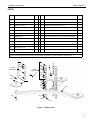
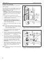
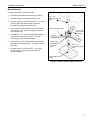
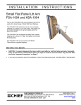
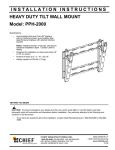
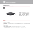
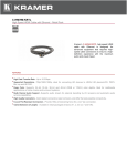
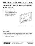
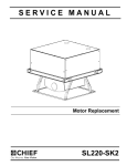
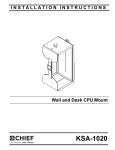
INSTALLATION INSTRUCTIONS
Vibration Mount
Model CMA-347
The Chief CMA-347 Vibration Mount is designed to
dampen shock and vibration between a mounted item
and its structural mounting surface.
Any lengths of standard NPT 1 1/2” pipe, threaded on
both ends, can be used to extend the height capabilities
to meet your needs.
BEFORE YOU BEGIN
CAUTION: To prevent damage to the mount, which could void factory warranty and affect the attached equipment,
thoroughly study all instructions and illustrations before you begin the installation. Pay particular attention to the
“Important Warnings and Precautions” on Page 1.
•
•
The maximum weight to be installed on the CMA-347 mount is 35 pounds (15.88 Kg).
If you have any questions about this installation, contact Chief Manufacturing at 1-800-582-6480.
CHIEF MANUFACTURING INC.
1-800-582-6480 952-894-6280 FAX 952-894-6918
8401 EAGLE CREEK PARKWAY, STE 700
SAVAGE, MINNESOTA 55378 USA
8803-000044 (Rev. D)
2007 Chief Manufacturing
www.chiefmfg.com
09/07
Model CMA-347
Installation Instructions
IMPORTANT WARNINGS AND CAUTIONS!
WARNING: A WARNING alerts you to the possibility of serious injury or death if you do not follow the instructions.
CAUTION: A CAUTION alerts you to the possibility of damage or destruction of equipment if you do not follow the
corresponding instructions.
WARNING: Improper installation can result in serious personal injury! Make sure that the structural members can
support a weight factor five times the total weight of the equipment. If not, reinforce the structure before installing the
mount.
WARNING: Be aware also of the potential for personal injury or damage to the unit if it is not adequately mounted.
WARNING: The installer is responsible for verifying that the structure to which the mount is anchored will safely
support four times the combined load of all attached components or other equipment.
WARNING: The weight of the display placed on the CMA-347 must not exceed 35 lbs. (15.88 kg), the maximum
load capacity of the CMA-347.
CAUTION: Check the unit for shipping damage before you begin the installation.
CONTENTS
IMPORTANT WARNINGS AND CAUTIONS! .............................. 2
PARTS .......................................................................................... 3
INSPECT MOUNT BEFORE INSTALLATION ............................. 4
MOUNT INSTALLATION .............................................................. 4
Set-Up .......................................................................................... 5
Set-up For 15 Pounds and Under .....................................5
Set-up For Over 15 Pounds ..............................................6
Mount Removal ............................................................................ 7
2
Installation Instructions
Model CMA-347
PARTS
Item
Nomenclature
Qty
.
Item
Nomenclature
Qty.
10
CMA-347 Top
1
130
WASHER, Fender, 1” OD
24
20
CMA-347 Bottom
1
140
NUT,Nylock, 3/8-16
3
30
WEIGHT, 2.5 Pound
3
150
SCREW, Cap, Hex Head, 3/8-16 x 1.5”
3
40
DAMPER, Sorbothane, Stepped
3
160
SCREW, Set, Socket Head, 5/16-18x3/8” (not shown)
2
50
DAMPER, Sorbothane
12
170*
KEY, Hex, 5/32” (not shown)
1
60
WASHER, Flat, 1/4”
3
180
Plate, Ceiling, Projector Mounting (not shown or supplied)
1
70
SPRING, Small
6
190
Pipe, Upper mounting, NPT 1 1/2" (not shown or supplied)
1
80
SPRING, Long Medium Gauge
3
200
Pipe, Lower Mounting, NPT 1 1/2" (not shown or supplied)
1
90*
SPRING, Long Heavy Gauge
3
210
Mount, Projector (not shown or supplied)
1
100*
BUSHING, Vibration, Stepped
6
110
NUT, Nylock, 1/4-20
3
120
BOLT, Hex Tap, 1/4-20 x 4”
3
* Items 90 - 100 are included in the accessory pack and used when configuring mount for applications over 15lbs..
Items 160 and 170 are located in the accessory pack and used in all applications to install the CMA-347 Vibration Mount.
120
60
100
120
15-35lb
Applications
0-15lb
Applications
90
130
50
130
80
(10)
130
140
50
100
130
30
150
130
50
130
70
130
50
(20)
40
130
110
Figure 1: CMA-347 Parts
3
Model CMA-347
INSPECT MOUNT BEFORE INSTALLATION
1. Carefully inspect the mount for shipping damage
(see figure 1). If any damage is apparent, call your
carrier claims agent and do not continue with the
installation until the carrier has reviewed the damage.
NOTE: Read all assembly instructions before starting
set-up or installation.
2. Carefully inspect mount components for damage.
MOUNT INSTALLATION
Installation Instructions
lower mounting pipe (200).
7. Thread projector mount (210) onto lower NPT 1 1/2"
lower mounting pipe (200).
8. Secure NPT 1 1/2” lower mounting pipe (200) to
projector mount (210) following the installation
instructions provided with the projector mount (210).
9. With the weight of the installation on the CMA-347,
tighten the 1/4-20 x 4" tap bolts until a slight preload
is on the springs.
The mount is shipped pre-assembled for applications
under 15 pounds.
CAUTION: If the total combined weight of the
projector, projector mount, and lower mounting pipe
exceeds 15lbs, the CMA 347 vibration mount needs to
be reconfigured for weights over 15lbs. Weigh all parts
before beginning installation.
If the total combined weight of the projector, projector
mount, and lower mounting pipe is 15lbs or below,
proceed with mount installation. If the total combined
weight of the projector, projector mount, and lower
mounting pipe is over 15lbs, see Set-Up for Over 15 lbs
on page 6.
NOTE: Keep the vibration mount as close as possible to
the projector by minimizing the length of the lower
mounting pipe.
1. Thread Upper mounting pipe (190) into Ceiling plate
(180).
Ceiling Plate (180)
NPT 1 1/2"
Upper Mounting Pipe (190)
CMA 347 Vibration Mount
5/16-18 x 3/8"
Socket Head
Set Screw
(160)
5/16-18 x 3/8"
Socket Head
Set Screw
(160)
2. Secure NPT 1 1/2” upper mounting pipe (190) to
ceiling plate (180) following the installation
instructions provided with the ceiling plate (180).
3. Thread mount top (10) onto NPT 1 1/2” upper
mounting pipe (190).
NOTE: Ensure there is no direct contact between mount
and surrounding structure. Any contact could
allow vibration transfer to the projector.
4. Secure NPT 1 1/2” upper mounting pipe (190) to
mount top (10) using 5/16-18 x 3/8" socket head set
screw (160). Turn 5/16/18 x 3/8" socket head set
screw (160) until it contacts thread of NPT 1 1/2”
upper mounting pipe (190).
5. Thread NPT 1 1/2” lower mounting pipe (200) into
mount bottom (20).
6. Secure NPT 1 1/2” lower mounting pipe (200) to
mount bottom (20) using 5/16-18 x 3/8" socket head
set screw (160). Turn 5/16/18 x 3/8" socket head set
screw (160) until it contacts thread of NPT 1 1/2”
4
NPT 1 1/2"
Lower Mounting Pipe
(200)
Projector Mount (210)
Figure 2: CMA 347 Vibration Mount Installation
Installation Instructions
Model CMA-347
Set-Up
Set-up For 15 Pounds and Under
The mount is shipped pre-assembled for applications
under 15 pounds. If the total combined weight of the
projector, projector mount, and lower mounting pipe is
15lbs or below, proceed with mount installation.
(see MOUNT INSTALLATION on page 4)
For applications over 15 pounds, proceed to “Set-up For
Over 15 Pounds”.
If the mount has been previously set-up to accommodate
a weight of 15-35lbs, it needs to be reconfigured to work
properly with weights below 15lbs.
(120)
(60)
(10)
A (100)
(90)
(100)
(20)
B
To set-up the mount for applications under 15lbs:
1. Un-install mount following the instructions outlined in
the Removal section of this document.
(see Mount Removal on page 7)
2. Loosen and remove 1/4-20 Nylock nut (110), 1/4"
fender washer (130), and stepped sorbothane
damper (40) located underneath mount arm and set
aside for reuse. (see figure 3)
3. Slide 1/4-20 x 4" tap bolt (120) upward, out of mount
top (10).
NOTE: Make cetrtain hardware group B (see figure 3)
and (see figure 4) stays in place when removing
1/4-20 x 4" tap bolt (120) and associated
hardware.
4. Remove hardware group A (see figure 3) keeping
1/4-20 x tap bolt (120) for reuse in 0-15lb
configuration.
5. Install 1/4" fender washers (130), sorbothane
dampers (50), and long medium gauge spring (80),
onto 1/4-20 x 4" tap bolt (120). (see figure 4)
6. Insert 1/4-20 x 4" tap bolt (120) with washers and
dampers through mount top (10), group B hardware
(see figure 6), and mount bottom (20). (see figure 4)
7. Install stepped sorbothane damper (40), fender
washer (130), and Nylock nut (110) onto 1/4-20 x 4"
tap bolt (120). (see figure 4)
(40)
(130)
(110)
Figure 3: Remove 35lb-15lb Application Hardware.
(120)
(130)
(50)
(10)
(130)
(80)
(130)
(50)
(130)
(50)
(130)
B (70)
(20)
(130)
(50)
(40)
(130)
(110)
8. Tighten until a slight preload is on the springs.
Repeat steps 2 through 8 for the remaining two hardware
sets.
Figure 4: Install 0-15lb Application Hardware.
5
Model CMA-347
Installation Instructions
Set-up For Over 15 Pounds
The mount is shipped pre-assembled for applications
under 15 pounds.
If the mount is set-up to accommodate a weight of up to
15lbs (as shipped), it needs to be reconfigured to work
properly with weights over 15lbs.
(120)
(130)
(50)
A (130)
WARNING: DO NOT attempt to reconfigure the mount
while installed. Properly un-install mount and place on
a flat stable surface before performing the procedure
below.
(80)
(130)
(50)
(130)
To set-up the mount for applications over 15lbs:
1. Un-install mount following the instructions outlined in
the Removal section of this document.
2. Loosen and remove 1/4-20 Nylock nut (110), 1/4"
fender washer (130), and stepped sorbothane
damper (40) located underneath mount arm and set
aside for reuse. (see figure 5)
(50)
B
(70)
4. Remove hardware group A (see figure 5) keeping
1/4-20 x tap bolt (120) for reuse in 15lb-35lb
configuration.
5. Install 1/4" machine washer (60), stepped dampers
(100), and long heavy gauge spring (90), onto 1/4-20
x 4" tap bolt (120).
(see figure 6)
6. Insert 1/4-20 x 4" tap bolt (120) with washers and
dampers through mount top (10), group B hardware
(see figure 6), and mount bottom (20). (see figure 6)
7. Install stepped sorbothane damper (40), fender
washer (130), and Nylock nut (110) onto 1/4-20 x 4"
tap bolt (120).
8. Tighten all the parts installed in Step 1, Step 2 and
Step 3 using a 1/4-20 x 4” tap bolt (120) and 1/4-20
Nylock nut (110) until a slight preload is on the
springs.
NOTE: Repeat steps 2 through 8 for the remaining two
hardware sets.
6
(20)
(130)
(50)
(40)
3. Slide 1/4-20 x 4" tap bolt (120) upward, out of mount
top (10).
NOTE: Make cetrtain hardware group B (see figure 5)
stays in place when removing 1/4-20 x 4" tap bolt
(120) and associated hardware.
(10)
(130)
(110)
Figure 5: Remove 0-15lb Application Hardware.
(120)
(60)
(10)
(100)
(90)
(100)
(20)
B
(40)
(130)
(110)
Figure 6: Install 15lb-35lb Application Hardware.
Installation Instructions
Model CMA-347
Mount Removal
To remove the CMA 347 vibration mount:
1. Disonnect power cables and wires from projector.
2. Uninstall projector from projector mount (210).
NPT 1 1/2"
Upper Mounting Pipe
(190)
3. Uninstall projector mount (210) from NPT 1 1/2” lower
mounting pipe (200) following the instructions
provided with the projector mount (210)
4. Loosen 5/16-18 x 3/8" socket head set screw (160)
securing NPT 1 1/2” lower mounting pipe (200) to
mount bottom (20).
CMA 347 Vibration Mount
5/16-18 x 3/8"
Socket Head
Set Screw
(160)
5. Uninstall NPT 1 1/2” lower mounting pipe (200) from
mount bottom (20) by turning NPT 1 1/2” lower
mounting pipe (200) counterclockwise.
6. Loosen 5/16-18 x 3/8" socket head set screw (160)
securing mount top (10) to NPT 1 1/2” upper mounting
pipe (190).
5/16-18 x 3/8"
Socket Head
Set Screw
(160)
7. Uninstall vibration mount from NPT 1 1/2” upper
mounting pipe (190) by turning mount top (10)
counterclockwise.
NPT 1 1/2"
Lower Mounting Pipe
(200)
Projector Mount
(210)
Figure 7: CMA 347 Vibration Mount Removal
7
Model CMA-347
8
Installation Instructions