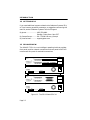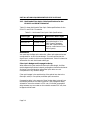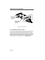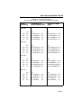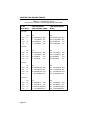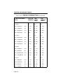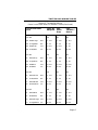
1
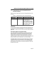
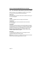
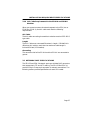
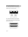
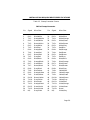
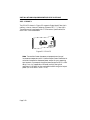
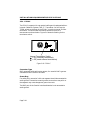
SEH-22, SEH-24, SEH-32, AND SEH-34
10BASE-T STACKABLE HUB
USER’S GUIDE
The Complete Networking Solution™
CABLETRON SYSTEMS, P. O. Box 5005, Rochester, NH 03866-5005
NOTICE
NOTICE
Cabletron Systems reserves the right to make changes in specifications and other
information contained in this document without prior notice. The reader should in all
cases consult Cabletron Systems to determine whether any such changes have been
made.
The hardware, firmware, or software described in this manual is subject to change
without notice.
IN NO EVENT SHALL CABLETRON SYSTEMS BE LIABLE FOR ANY INCIDENTAL,
INDIRECT, SPECIAL, OR CONSEQUENTIAL DAMAGES WHATSOEVER
(INCLUDING BUT NOT LIMITED TO LOST PROFITS) ARISING OUT OF OR
RELATED TO THIS MANUAL OR THE INFORMATION CONTAINED IN IT, EVEN
IF CABLETRON SYSTEMS HAS BEEN ADVISED OF, KNOWN, OR SHOULD HAVE
KNOWN, THE POSSIBILITY OF SUCH DAMAGES.
© Copyright February 1994 by:
Cabletron Systems, Inc.
P.O. Box 5005, Rochester, NH 03867-0505
All Rights Reserved
Printed in the United States of America
Order Number: 9030903-01 February 94
SPECTRUM®, LANVIEW®, Remote LANVIEW® , HubSTACK™ , and
MicroMMAC™ are trademarks of Cabletron Systems, Inc.
IBM is a registered trademark of International Business Machines Corporation.
CompuServe is a registered trademark of CompuServe, Inc.
DEC, VT200, and VT300 are trademarks of Digital Equipment Corporation.
Ethernet is a trademark of Xerox Corporation.
Windows is a registered trademark of Microsoft Corporation.
Printed On
Recycled Paper
i
NOTICE
FCC NOTICE
This device complies with Part 15 of the FCC rules. Operation is subject to the following
two conditions: (1) this device may not cause harmful interference, and (2) this device
must accept any interference received, including interference that may cause undesired
operation.
NOTE: This equipment has been tested and found to comply with the limits for a Class
A digital device, pursuant to Part 15 of the FCC rules. These limits are designed to
provide reasonable protection against harmful interference when the equipment is
operated in a commercial environment. This equipment uses, generates, and can radiate
radio frequency energy and if not installed in accordance with the operator’s manual,
may cause harmful interference to radio communications. Operation of this equipment
in a residential area is likely to cause interference in which case the user will be required
to correct the interference at his own expense.
WARNING: Changes or modifications made to this device which are not expressly
approved by the party responsible for compliance could void the user’s authority to
operate the equipment.
DOC NOTICE
This digital apparatus does not exceed the Class A limits for radio noise emissions from
digital apparatus set out in the Radio Interference Regulations of the Canadian
Department of Communications.
Le présent appareil numérique n’émet pas de bruits radioélectriques dépassant les
limites applicables aux appareils numériques de la class A prescrites dans le Règlement
sur le brouillage radioélectrique édicté par le ministère des Communications du Canada.
ii
NOTICE
CABLETRON SYSTEMS, INC.
PROGRAM LICENSE AGREEMENT
IMPORTANT:
Before utilizing this product, carefully read this License Agreement.
This document is an agreement between you, the end user, and Cabletron Systems, Inc.
(“Cabletron”) that sets forth your rights and obligations with respect to the Cabletron
software program (the “Program”) contained in this package. The Program may be
contained in firmware, chips or other media. BY UTILIZING THE ENCLOSED
PRODUCT, YOU ARE AGREEING TO BECOME BOUND BY THE TERMS OF THIS
AGREEMENT, WHICH INCLUDES THE LICENSE AND THE LIMITATION OF
WARRANTY AND DISCLAIMER OF LIABILITY. IF YOU DO NOT AGREE TO THE
TERMS OF THIS AGREEMENT, PROMPTLY RETURN THE UNUSED PRODUCT TO
THE PLACE OF PURCHASE FOR A FULL REFUND.
CABLETRON SOFTWARE PROGRAM LICENSE
1.
LICENSE. You have the right to use only the one (1) copy of the Program provided
in this package subject to the terms and conditions of this License Agreement.
You may not copy, reproduce or transmit any part of the Program except as
permitted by the Copyright Act of the United States or as authorized in writing by
Cabletron.
2.
OTHER RESTRICTIONS. You may not reverse engineer, decompile, or
disassemble the Program.
3.
APPLICABLE LAW. This License Agreement shall be interpreted and governed
under the laws and in the state and federal courts of New Hampshire. You accept
the personal jurisdiction and venue of the New Hampshire courts.
iii
NOTICE
EXCLUSION OF WARRANTY
AND DISCLAIMER OF LIABILITY
1.
EXCLUSION OF WARRANTY. Except as may be specifically provided by
Cabletron in writing, Cabletron makes no warranty, expressed or implied,
concerning the Program (including Its documentation and media).
CABLETRON DISCLAIMS ALL WARRANTIES, OTHER THAN THOSE
SUPPLIED TO YOU BY CABLETRON IN WRITING, EITHER EXPRESS OR
IMPLIED, INCLUDING BUT NOT LIMITED TO IMPLIED WARRANTIES OF
MERCHANTABLITY AND FITNESS FOR A PARTICULAR PURPOSE, WITH
RESPECT TO THE PROGRAM, THE ACCOMPANYING WRITTEN MATERIALS,
AND ANY ACCOMPANYING HARDWARE.
2.
NO LIABILITY FOR CONSEQUENTIAL DAMAGES. IN NO EVENT SHALL
CABLETRON OR ITS SUPPLIERS BE LIABLE FOR ANY DAMAGES
WHATSOEVER (INCLUDING, WITHOUT LIMITATION, DAMAGES FOR LOSS
OF BUSINESS, PROFITS, BUSINESS INTERRUPTION, LOSS OF BUSINESS
INFORMATION, SPECIAL, INCIDENTAL, CONSEQUENTIAL, OR RELIANCE
DAMAGES, OR OTHER LOSS) ARISING OUT OF THE USE OR INABILITY TO
USE THIS CABLETRON PRODUCT, EVEN IF CABLETRON HAS BEEN
ADVISED OF THE POSSIBILITY OF SUCH DAMAGES. BECAUSE SOME
STATES DO NOT ALLOW THE EXCLUSION OR LIMITATION OF LIABILITY
FOR CONSEQUENTIAL OR INCIDENTAL DAMAGES, OR ON THE DURATION
OR LIMITATION OF IMPLIED WARRANTEES IN SOME INSTANCES THE
ABOVE LIMITATIONS AND EXCLUSIONS MAY NOT APPLY TO YOU.
UNITED STATES GOVERNMENT
RESTRICTED RIGHTS
The enclosed product (a) was developed solely at private expense; (b) contains “restricted
computer software” submitted with restricted rights in accordance with Section 5222719 (a) through (d) of the Commercial Computer Software - Restricted Rights Clause and
its successors, and (c) in all respects is proprietary data belonging to Cabletron and/or its
suppliers.
For Department of Defense units, the product is licensed with “Restricted Rights” as
defined in the DoD Supplement to the Federal Acquisition Regulations, Section 52.2277013 (c) (1) (ii) and its successors, and use, duplication, disclosure by the Government is
subject to restrictions as set forth in subparagraph (c) (1) (ii) of the Rights in Technical
Data and Computer Software clause at 252.227-7013. Cabletron Systems, Inc., 35
Industrial Way. Rochester, New Hampshire 03867
iv
CONTENTS
TABLE OF CONTENTS
APPENDIX A
CHAPTER 1
1.1
1.2
1.3
1.4
1.5
1.6
1.7
2.2
2.3
2.4
2.5
INTRODUCTION
USING THIS MANUAL ............................................................ 1-1
GETTING HELP........................................................................ 1-2
SEH OVERVIEW ....................................................................... 1-2
SEH FEATURES ....................................................................... 1-3
STACKABLE CAPABILITIES .................................................. 1-4
OPTIONAL FEATURES ........................................................... 1-4
RELATED MANUALS .............................................................. 1-5
CHAPTER 2
2.1
TABLE OF CONTENTS v
INSTALLATION
REQUIREMENTS/SPECIFICATIONS
CABLE SPECIFICATIONS....................................................... 2-1
2.1.1 HubSTACK Interconnect Cable Requirements........... 2-1
2.1.2 UTP and STP Cable Specifications for the Network Ports
and EPIM-T Module...................................................... 2-2
2.1.3 Multimode Fiber Optic Cable Specifications for the
EPIM-F1 and EPIM-F2 Modules ................................. 2-4
2.1.4 Single Mode Fiber Optic Cable Specifications for
the EPIM-F3 Module .................................................... 2-5
2.1.5 Thin-net Network Requirements for the EPIM-C Module
2-6
2.1.6 AUI Cable Requirements for the EPIM-A and EPIM-X
Modules.......................................................................... 2-7
NETWORK PORT SPECIFICATIONS .................................... 2-7
2.2.1 SEH-22 and SEH-24 Network Port Specifications...... 2-8
2.2.2 SEH-32 and SEH-34 Network Port Specifications...... 2-8
EPIM SPECIFICATIONS ....................................................... 2-10
2.3.1 EPIM-T ........................................................................ 2-10
2.3.2 EPIM-F1/F2 .................................................................2-11
2.3.3 EPIM-F3 ...................................................................... 2-12
2.3.4 EPIM-C ........................................................................ 2-14
2.3.5 EPIM-A and EPIM-X (AUI Port)................................ 2-15
TRANSCEIVER REQUIREMENTS ....................................... 2-16
OPERATING SPECIFICATIONS........................................... 2-16
v
CONTENTS
CHAPTER 3
3.1
3.2
3.3
UNPACKING THE SEH............................................................3-1
INSTALLING THE SEH............................................................3-1
3.2.1 Stacking the SEH ..........................................................3-2
3.2.2 Attaching the Strain Relief Bracket.............................3-4
3.2.3 Rack Mounting the SEH ...............................................3-5
3.2.4 Wall Mounting the SEH................................................3-6
3.2.5 Free-Standing Installation............................................3-7
CONNECTING THE SEH TO THE POWER SOURCE ..........3-8
CHAPTER 4
4.1
4.2
TROUBLESHOOTING
INSTALLATION CHECK-OUT ................................................5-1
USING LANVIEW......................................................................5-2
APPENDIX B
vi
CONNECTING TO THE NETWORK
CONNECTING THE SEH TO THE NETWORK .....................4-1
4.1.1 Connecting Network Ports SEH-22 and SEH-24.........4-1
4.1.2 Connecting Network Ports SEH-32 and SEH-34.........4-3
4.1.3 Connecting a UTP Segment to an EPIM-T ..................4-4
4.1.4 Connecting a Fiber Optic Link Segment to an EPIM-F1,
EPIM-F2, or EPIM-F34-5
4.1.5 Connecting a Thin-Net Segment to an EPIM-C ..........4-8
4.1.6 Connecting an AUI Cable to an EPIM-A ...................4-10
4.1.7 Connecting an AUI Cable to an EPIM-X....................4-11
FINISHING THE INSTALLATION........................................4-12
CHAPTER 5
5.1
5.2
INSTALLATION
TWISTED PAIR WIRING TABLES A-1
INTRODUCTION
CHAPTER 1
INTRODUCTION
Welcome to the Cabletron Systems SEH-22, SEH-24, SEH-32, and
SEH-34 10BASE-T Stackable Hub User’s Guide. This manual
explains installation instructions and provides reference information
for the SEH-22, 24, 32, and 34.
Note: The term SEH (Stackable Ethernet Hub) is used throughout this
manual when describing features and functions that are common to the
SEH-22, 24, 32, and 34.
1.1
USING THIS MANUAL
Read through this manual completely to familiarize yourself with its
content and to gain an understanding of the features and capabilities
of the SEH. A general working knowledge of Ethernet and IEEE 802.3
type data communications networks and their physical layer
components will be helpful when installing the SEH.
Chapter 1, Introduction, outlines the contents of this manual, briefly
describes SEH features, and concludes with a list of related manuals.
Chapter 2, Installation Requirements/Specifications, describes
installation requirements, network guidelines, and SEH operating
specifications.
Chapter 3, Installation, contains instructions for installing your SEH
as a stackable or stand-alone hub.
Chapter 4, Connecting to the Network, explains how to connect the
SEH to the network using the various media types.
Chapter 5, Troubleshooting, describes how to use the LANVIEW
LEDs to troubleshoot network problems.
Appendix A, Twisted Pair Wiring Tables, contains wiring pinouts
for Punch Down Block applications.
Page 1-1
INTRODUCTION
1.2
GETTING HELP
If you need additional support related to the Cabletron Systems SEH,
or if you have any questions, comments, or suggestions concerning this
manual, contact Cabletron Systems Technical Support:
By phone ......................... (603) 332-9400
Monday-Friday; 8am - 8pm EST
®
By CompuServe ............ GO CTRON from any ! prompt
By Internet mail ............. [email protected]
1.3
SEH OVERVIEW
The 10BASE-T SEH is a non-intelligent repeating hub that provides
front panel ports for network connections and rear panel HubSTACK
Interconnect Bus ports for stackable connections.
EPIM-2
HubSTACK 10BASE-T HUB WITH LANVIEW®
SEH-24
RCV
LNK
E
24 23 22 21 20 19 18 17 16 15 14 13 2
PWR
MGMT
CLN
RCV
LNK
12 11 10 9 8 7 6 5 4 3 2 1
E
1
24X
23X
22X
21X
12X
11X
10X
9X
20X 19X
8X
7X
18X
17X
16X
6X
5X
4X
15X
3X
14X 13X
2X
1X
EPIM-1
SEH-24 10BASE-T HUB WITH LANVIEW®
OUT
SEH INTERCONNECT
IN
EPIM-2
HubSTACK 10BASE-T HUB WITH LANVIEW®
SEH-34
RCV
LNK
E
24 23 22 21 20 19 18 17 16 15 14 13 2
PWR
MGMT
CLN
RCV
LNK
12 11 10 9 8 7 6 5 4 3 2 1
E
1
24X
13X
12X
1X
EPIM-1
SEH-34 10BASE-T HUB WITH LANVIEW®
OUT
SEH INTERCONNECT
IN
Figure 1-1. The SEH-24 and SEH-34
Page 1-2
INTRODUCTION
You can stack together up to five SEH hubs using Cabletron Systems’
external HubSTACK Interconnect cables. If you want to add
management to the stack, Cabletron Systems offers the MicroMMAC
and the SEHI intelligent hubs. You can stack up to four SEHs with
one intelligent hub. Stackable configurations let you maintain only
one IEEE repeater hop while providing up to 130 Ethernet ports.
The SEH-22/24 and SEH-32/34 are functionally identical with the
exception of the network ports:
1.4
•
SEH-22, 12 RJ45 network ports and one EPIM port.
•
SEH-24, 24 RJ45 network ports and two EPIM ports.
•
SEH-32, one 50 pin Champ connector, providing 12 twisted
pair segments, and one EPIM port.
•
SEH-34, two 50 pin Champ connectors, providing 24 twisted
pair segments, and two EPIM ports.
SEH FEATURES
Repeater Functionality
The SEH fully conforms to the IEEE 802.3 Repeater, AUI, and
10BASE-T specifications, and provides the flexibility to connect
networks using IEEE 802.3, Ethernet Version 1 or Version 2
equipment. The SEH transmits re-timed data packets, regenerates the
preamble, extends fragments, and arbitrates collisions.
The SEH automatically partitions problem segments, and reconnects
repaired segments to the network. This feature minimizes the impact
on network operation by isolating the problem segment. Only devices
on the problem segment are affected. When the problem is solved, the
SEH automatically reconnects the isolated segment to the network.
Polarity Detection and Correction
Each twisted pair port on the SEH incorporates a Polarity Detection
and Correction feature that allows the SEH to pass data regardless of
the polarity of the twisted pair segment’s receive link. We do not
recommend operating in this condition. If you discover this condition,
remove the segment from the network and wire it correctly. This
reduces the potential for problems if equipment changes are made.
Page 1-3
INTRODUCTION
LANVIEW LEDs
Cabletron Systems’ LANVIEW Status Monitoring and Diagnostics
System is a troubleshooting tool that helps you diagnose power
failures, collisions, cable faults, and link problems. The LANVIEW
LEDs are conveniently located on the front panel.
1.5
STACKABLE CAPABILITIES
The SEH is a non-intelligent hub designed to be managed by either
the Cabletron Systems SEHI intelligent hub or the Cabletron Systems
MicroMMAC intelligent hub. Intelligent hubs serve as the logical “top”
of the stack. They manage all SEH hubs in the stack providing full
packet and error statistics for the entire stack, individual device, or
individual port. You can stack together up to five SEHs for a
non-managed stack or one intelligent hub and up to four SEHs for a
managed stack. You can also add or remove hubs from the stack
without having to power down.
1.6
OPTIONAL FEATURES
The following features are not included with the SEH but can be
purchased separately from Cabletron Systems.
Ethernet Port Interface Modules (EPIMs)
EPIMs let you expand your network through a variety of media.
Cabletron offers the EPIMs shown in Table 1-1.
Table 1-1. EPIMs
EPIM
Media Type
Connector
EPIM-A
AUI
DB15 (Female)
EPIM-C
10BASE-2 Thin Coaxial
BNC
EPIM-T
10BASE-T Unshielded
Twisted Pair
RJ45
EPIM-X
Standard Transceiver
DB15 (Male)
EPIM-F1
Multimode Fiber
SMA
EPIM-F2
Multimode Fiber
ST
EPIM-F3
Single Mode Fiber
ST
Page 1-4
INTRODUCTION
Daughter Board Upgrade Kit
You can upgrade the SEH-22 and the SEH-32 to 24 ports using the
daughter board upgrade kit. The Cabletron part numbers for the
upgrades are:
•
SEH-22:
24PORT-UGKT-E
•
SEH-32:
24PORT-UGKT-E 50P
HubSTACK Interconnect Cables
You need Cabletron’s HubSTACK Interconnect cables to stack hubs
together. Table 1-2 lists the part number and application for each
cable.
Table 1-2. HubSTACK Interconnect Cables
Part
Number
Description
Application
9380110
12" HubSTACK
Interconnect Cable
SEH to SEH connections.
9380111
18" HubSTACK
Interconnect Cable
SEHI or MicroMMAC to
SEH connections.
Rack Mount or Wall Mount Hardware
You can install your SEH in a 19-inch rack or mount it on a wall.
Cabletron offers an accessory package that includes brackets and
mounting screws. The part number for the accessory package is
SEH-ACCY-KIT.
1.7
RELATED MANUALS
Us the SEHI-22/24 and SEHI-32/34 User’s Guide and the
MicroMMAC-22E/24E and MicroMMAC-32E/34E User’s Guide to
supplement the procedures and other technical data provided in this
manual. The procedures contained in these manuals are referenced
where appropriate, rather than repeated in this manual.
Page 1-5
INSTALLATION REQUIREMENTS/SPECIFICATIONS
CHAPTER 2
INSTALLATION
REQUIREMENTS/SPECIFICATIONS
This chapter describes network guidelines, power requirements, and
operating specifications for the SEH. Be sure to read this chapter
before you install the SEH. Your network must meet the requirements
and conditions specified in this chapter to obtain satisfactory
performance from this equipment. Failure to follow these guidelines
could result in poor network performance.
2.1
CABLE SPECIFICATIONS
The SEH network ports support both Shielded Twisted Pair (STP) or
Unshielded Twisted Pair (UTP) cabling. The Ethernet Port Interface
Modules (EPIMs) let you expand your network using UTP, STP,
Multimode Fiber Optic, Single Mode Fiber Optic, or Thin Coaxial
cabling. The rear panel Interconnect Bus Ports support Cabletron
Systems’ HubSTACK Interconnect cables for stackable applications.
Take care in planning and preparing the cabling and connections for
your network. The quality of the connections and the length of cables
are critical factors in determining the reliability of your network. The
following sections describe specifications for each media type.
2.1.1
HubSTACK Interconnect Cable Requirements
You connect units in the stack with HubSTACK Interconnect cables.
Refer to Chapter 1 for cable part numbers. The cables attach to the
SEH’s rear panel bus ports.
The rear panel of the SEH has an SEH Interconnect Bus Out Port
(male connector) and an SEH Interconnect Bus In Port (female
connector). The bus supports five stackable devices.
Page 2-1
INSTALLATION REQUIREMENTS/SPECIFICATIONS
2.1.2
UTP and STP Cable Specifications for the Network Ports
and EPIM-T Module
The device at the other end of the twisted pair segment must meet
IEEE 802.3 10BASE-T specifications. When you connect a 10BASE-T
Twisted Pair Segment to the SEH’s 10BASE-T Twisted Pair Network
Ports and EPIM-T module, your network must meet the following
requirements:
Length
The IEEE 802.3 10BASE-T standard requires that 10BASE-T devices
transmit over a 100 meter (328 foot) link using 22-24 AWG unshielded
twisted pair wire. However, cable quality largely determines
maximum link length. If you use high quality, low attenuation cable,
you can achieve link lengths of up to 200 meters. Cable delay limits
maximum link length to 200 meters, regardless of the cable type.
Insertion Loss
The maximum insertion loss allowed for a 10BASE-T link is 11.5 dB
at all frequencies between 5.0 and 10 MHz. This includes the
attenuation of the cables, connectors, patch panels, and reflection
losses due to impedance mismatches in the link segment.
Impedance
Cabletron Systems 10BASE-T Twisted Pair products will work on
twisted pair cable with 75 to 165 ohms impedance. Unshielded twisted
pair cables typically have an impedance of between 85 to 110 ohms.
Shielded twisted pair cables, such as IBM Type 1 cable, can also be
used. You should remember that the impedance of IBM Type 1 cable is
typically 150 ohms. This increases the signal reflection caused by the
cable, but since the cable is shielded, this signal reflection has little
effect on the received signal’s quality due to the lack of crosstalk
between the shielded cable pairs.
Jitter
Intersymbol interference and reflections can cause jitter in the bit cell
timing, resulting in data errors. A 10BASE-T link must not generate
more than 5.0 nsec. of jitter. If your cable meets the impedance
requirements for a 10BASE-T link, jitter should not be a concern.
Page 2-2
INSTALLATION REQUIREMENTS/SPECIFICATIONS
Delay
The maximum propagation delay of a 10BASE-T link segment must
not exceed 1000 nsec. This 1000 nsec. maximum delay limits the
maximum link segment length to no greater than 200 meters.
Crosstalk
Crosstalk is caused by signal coupling between the different cable
pairs contained within a multi-pair cable bundle. 10BASE-T
transceivers are designed so that the user does not need to be
concerned about cable crosstalk, provided the cable meets all other
requirements.
Noise
Noise can be caused by either crosstalk or externally induced
impulses. Impulse noise may cause data errors if the impulses occur at
very specific times during data transmission. Generally, the user need
not be concerned about noise. If noise-related data errors are
suspected, it may be necessary to either reroute the cable or eliminate
the source of the impulse noise.
Temperature
Multi-pair PVC 24 AWG telephone cables typically have an
attenuation of approximately 8 to 10 dB/100m at 20°C (78°F). The
attenuation of PVC insulated cable varies significantly with
temperature. At temperatures greater than 40°C (104°F), we strongly
recommend that you use plenum-rated cables to ensure that cable
attenuation remains within specification.
Page 2-3
INSTALLATION REQUIREMENTS/SPECIFICATIONS
2.1.3
Multimode Fiber Optic Cable Specifications for the
EPIM-F1 and EPIM-F2 Modules
Table 2-1 shows Multimode Fiber Optic Cable specifications for the
EPIM-F1 and EPIM-F2 modules.
Table 2-1. Multimode Fiber Optic Cable Specifications
Cable Type
Attenuation
Maximum Cable Length
50/125 µm
13.0 dB or less
62.5/125 µm
16.0 dB or less
100/140 µm
19.0 dB or less
The maximum allowable fiber
optic cable length is 2 km
(2187.2 yards). However,
IEEE 802.3 specifications
allow for a maximum of 1 km
(1093.6 yards).
Attenuation
You must test the fiber optic cable with a fiber optic attenuation test
set adjusted for an 850 nm wavelength. This test verifies that the
signal loss in a cable is within an acceptable level. Table 2-1 shows the
attenuation for each Multimode cable type.
Fiber Optic Budget and Propagation Delay
When determining the maximum fiber optic cable length, the fiber
optic budget delay and total network propagation should be calculated
and taken into consideration before fiber optic cable runs are
incorporated in any network design.
Fiber optic budget is the combination of the optical loss due to the
fiber optic cable, in-line splices, and fiber optic connectors.
Propagation delay is the amount of time it takes data to travel from
the sending device to the receiving device. Total propagation delay
allowed for the entire network is 25.6 µsec, if the total propagation
delay between any two nodes on the network exceeds 25.6 µsec, then
bridges should be used.
Page 2-4
INSTALLATION REQUIREMENTS/SPECIFICATIONS
2.1.4
Single Mode Fiber Optic Cable Specifications for
the EPIM-F3 Module
Table 2-2 shows Single Mode Fiber Optic Cable specifications for the
EPIM-F3.
Table 2-2. Single Mode Fiber Optic Cable Specifications
Cable Type
Attenuation
Maximum Cable Length
8/125-12/125 µm
10.0 dB or less
The maximum allowable fiber
optic cable length is
5 km (3.1 miles) with bridges
at each segment end. However, IEEE 802.3 FOIRL specifications specify a maximum of
1 km (1093.6 yards).
Attenuation
You must test the fiber optic cable with a fiber optic attenuation test
set adjusted for an 1300 nm wavelength. This test verifies that the
signal loss in a cable is 10.0 dB or less for any given single mode fiber
optic link.
Fiber Optic Budget and Propagation Delay
Fiber optic budget is the combination of the optical loss due to the
fiber optic cable, in-line splices, and fiber optic connectors. When
determining the maximum fiber optic cable length, the fiber optic
budget (total loss of 10.0 dB or less between stations) and total
network propagation delay should be calculated and considered before
fiber optic cable runs are incorporated in any network design.
Propagation delay is the amount of time it takes data to travel from
the sending device to the receiving device. Total propagation delay
allowed for the entire network is 25.6 µsec, if the total propagation
delay between any two nodes on the network exceeds 25.6 µsec, then
bridges should be used.
Page 2-5
INSTALLATION REQUIREMENTS/SPECIFICATIONS
2.1.5
Thin-net Network Requirements for the EPIM-C Module
When you connect a thin-net segment to the SEH (via an EPIM-C),
your network must meet the following requirements:
Cable Type
50 ohm RG-58A/U type coaxial cable must be used when making up a
thin-net cable segment.
Length
The thin-net segment must be no longer than 185 meters.
Terminators
A 50 ohm terminator must be connected to the far end of each
thin-net segment.
Connectors
A maximum of 29 tee-connectors may be used throughout the length
of cable segment for host connections. If an excessive number of barrel
connectors are used within the cable segment, such as finished wall
plates with BNC feed-throughs, then a reduced number of host
connections may be required. For special network design, contact
Cabletron Systems Technical Support.
Grounding
For safety, ground only one end of a thin-net segment. Do NOT
connect EPIM BNC ports to earth ground.
Warning: Connecting a thin-net segment to earth ground at more than
one point could produce dangerous ground currents.
Page 2-6
INSTALLATION REQUIREMENTS/SPECIFICATIONS
2.1.6
AUI Cable Requirements for the EPIM-A and EPIM-X
Modules
When you connect an external network segment to the SEH (via an
EPIM-A or EPIM-X), the AUI cable must meet the following
requirements:
AUI Cable
The AUI cable connecting the module to a device must be IEEE 802.3
type cable.
Length
The AUI Cable must not exceed 50 meters in length. If 28 AWG thin
office drop AUI cable is used, then the maximum cable length is
limited to 50 feet (15.24 meters).
Grounding
The connector shell of the EPIM-A and the EPIM-X are connected to
ground.
2.2
NETWORK PORT SPECIFICATIONS
The SEH-22 and SEH-24 network ports are shielded RJ45 connectors
that support both STP and UTP cabling. The SEH-32 and SEH-34
provide a 50 pin Champ style connector for network connections. The
following sections provide specifications for each SEH model.
Page 2-7
INSTALLATION REQUIREMENTS/SPECIFICATIONS
2.2.1
SEH-22 and SEH-24 Network Port Specifications
The SEH-22 and SEH-24 provide RJ45 connections for network
connections. Figure 2-1 shows the RJ45 pinouts.
12345678
12X
1. Receive +
2. Receive 3. Transmit +
4. Not Used
11X
10X
5. Not Used
6. Transmit 7. Not Used
8. Not Used
Figure 2-1. RJ45 Network Ports
2.2.2
SEH-32 and SEH-34 Network Port Specifications
The SEH-32 and SEH-34 provide 50 pin Champ connectors for
network connections as shown in Figure 2-2. Table 2-3 shows the
pinouts for the Champ connector.
24X
13X
12X
1X
Figure 2-2. SEH-34 Network Ports
Page 2-8
INSTALLATION REQUIREMENTS/SPECIFICATIONS
Table 2-3. Champ Connector Pinouts
50 Pin Champ Connector
Pin
Signal
Wire Color
Pin
Signal
Wire Color
1
2
3
4
5
6
7
8
9
10
11
12
13
14
15
16
17
18
19
20
21
22
23
24
25
RX 1TX 1RX 2TX 2RX 3TX 3RX 4TX 4RX 5TX 5RX 6TX 6RX 7TX 7RX 8TX 8RX 9TX 9RX 10TX 10RX 11TX 11RX 12TX 12N/C
Blue/White
Orange/White
Green/White
Brown/White
Gray/White
Blue/Red
Orange/Red
Green/Red
Brown/Red
Gray/Red
Blue/Black
Orange/Black
Green/Black
Brown/Black
Gray/Black
Blue/Yellow
Orange/Yellow
Green/Yellow
Brown/Yellow
Gray/Yellow
Blue/Violet
Orange/Violet
Green/Violet
Brown/Violet
Gray/Violet
26
27
28
29
30
31
32
33
34
35
36
37
38
39
40
41
42
43
44
45
46
47
48
49
50
RX 1+
TX 1+
RX 2+
TX 2+
RX 3+
TX 3+
RX 4+
TX 4+
RX 5+
TX 5+
RX 6+
TX 6+
RX 7+
TX 7+
RX 8+
TX 8+
RX 9+
TX 9+
RX 10+
TX 10+
RX 11+
TX 11+
RX 12+
TX 12+
N/C
White/Blue
White/Orange
White/Green
White/Brown
White/Gray
Red/Blue
Red/Orange
Red/Green
Red/Brown
Red/Gray
Black/Blue
Black/Orange
Black/Green
Black/Brown
Black/Gray
Yellow/Blue
Yellow/Orange
Yellow/Green
Yellow/Brown
Yellow/Gray
Violet/Blue
Violet/Orange
Violet/Green
Brown
Violet/Gray
Page 2-9
INSTALLATION REQUIREMENTS/SPECIFICATIONS
2.3
EPIM SPECIFICATIONS
EPIMs let you connect the SEH to the main network using different
media types. Cabletron Systems offers a variety of EPIMs. The
following sections explain specifications for each EPIM.
2.3.1
EPIM-T
The EPIM-T is an RJ45 connector supporting UTP cabling. It has an
internal Cabletron Systems TPT-T™ 10BASE-T Twisted Pair
Transceiver.
The slide switch on the EPIM-T determines the cross-over status of
the cable pairs. If the switch is on the X side, the pairs are internally
crossed over. If the switch is on the = side, the pairs are not internally
crossed over. Figure 2-3 shows the pinouts for the EPIM-T in both
cross-over positions.
Position X
(crossed over)
1. RX+
2. RX3. TX+
4. NC
5. NC
6. TX7. NC
8. NC
Position =
(not crossed over)
1. TX+
2. TX3. RX+
4. NC
5. NC
6. RX7. NC
8. NC
Figure 2-3. EPIM-T Pinouts
Page 2-10
INSTALLATION REQUIREMENTS/SPECIFICATIONS
2.3.2
EPIM-F1/F2
The EPIM-F1 and EPIM-F2 shown in Figure 2-4 support Multimode
Fiber Optic cabling. Each EPIM has an internal Cabletron Systems
FOT-F™ Fiber Optic Transceiver. The EPIM-F1 is equipped with
SMA Connectors and the EPIM-F2 is equipped with ST Connectors.
Specifications for the EPIMs are listed below.
Figure 2-4. EPIM-F1 and EPIM-F2
Parameter
Receive
Sensitivity:
Peak Input
Power:
Typical
Value
Worst
Case
Worst Case Typical
Budget
Budget
-30.5 dBm -28.0 dBm
—
—
-7.6 dBm
—
—
-8.2 dBm
Transmitter Power
50/125 µm
fiber:
62.5/125 µm
fiber:
100/140 µm
fiber:
Error Rate:
-13.0 dBm -15.0 dBm 13.0 dB
17.5 dB
-10.0 dBm -12.0 dBm 16.0 dB
20.5 dB
-7.0 dBm -9.0 dBm
Better than 10-10
23.5 dB
19.0 dB
Note: The transmitter power levels and receive sensitivity levels
listed are Peak Power Levels after optical overshoot. A Peak Power
Meter must be used to correctly compare the values given above to
those measured on any particular port. If Power Levels are being
measured with an Average Power Meter, then 3 dBm must be added
to the measurement to correctly compare those measured values to
the values listed (i.e. -30.5 dBm peak=-33.5 dBm average).
Page 2-11
INSTALLATION REQUIREMENTS/SPECIFICATIONS
2.3.3
EPIM-F3
The EPIM-F3 shown in Figure 2-5 supports Single Mode Fiber Optic
cabling. It has an internal Cabletron Systems FOT-F™ Fiber Optic
Transceiver and is equipped with ST Connectors. Specifications for
the EPIM-F3 are listed below.
Figure 2-5. EPIM-F3
Note: Transmitter Power decreases as temperatures rise and
increases as temperatures fall. Use the Output Power Coefficient to
calculate increased or decreased power output for your operating
environment. For example, the typical power output at 25° C is -16.4
dBm. For a 4° C temperature increase, multiply the typical
coefficient (-0.15 dBm) by four and add the result to typical output
power (4 x -0.15 dBm + -16.4 = -17.0).
Page 2-12
INSTALLATION REQUIREMENTS/SPECIFICATIONS
Maximum Sensitivity (-36.0)
Receive
Sensitivity
Typical Sensitivity (-31.0)
Minimum Sensitivity (-30.0)
Minimum Receive Input (-9.72)
Typical Receive Input (-7.5)
Maximum
Receive
Input Power
Maximum Receive Input (-6.99)
Maximum Transmit Power (-12.0)
Transmitter Power*
(At 25°C into
8.3/125µm fiber)
Typical Transmit Power (-15.5)
Minimum Transmit Power (-21.0)
dBm
-40
-35
-30
-25
-20
-15
-10
-5
Less Power
0
More Power
* Transmit Power Typical Power
Coefficient
(See Note Below)-0.15dBm/
Minimum Power
°C
Maximum Power
-0.12 dBm/
°C-0.18 dBm/
°C
Parameter
Typical
Minimum
Maximum
Transmitter Peak
Wave Length
1300 nm
1270 nm
1330 nm
Spectral Width
60 nm
Rise Time/
Fall Time
3.0 nsec
2.5 nsec
2.7 nsec
2.2 nsec
5.0 nsec
5.0 nsec
Duty Cycle
50.1%
49.6%
50.7%
Bit Error Rate:
Better than 10-10
-
100 nm
Note: The transmitter power levels given above are Peak Power
Levels after optical overshoot. You must use a Peak Power Meter to
correctly compare the values given above to those measured on any
particular port. If you are measuring power levels with an Average
Power Meter, add 3 dBm to the average power measurement to
correctly compare the average power values measured to the values
listed above (i.e. -33.5 dBm average + 3 dB = -30.5 dBm peak).
Page 2-13
INSTALLATION REQUIREMENTS/SPECIFICATIONS
2.3.4
EPIM-C
The EPIM-C supports thin-net coaxial cabling and is equipped with an
internal Cabletron Systems TMS-3™ Transceiver. You can use the
TERM switch on the front of the EPIM-C to set the internal 50 Ohm
terminator. This eliminates the need to connect the port to a
tee-connector and terminator. Figure 2-6 shows the setting for the
terminator switch.
Internal Termination Switch
= On (internally terminated)
= Off (need external termination)
Figure 2-6. EPIM-C
Connector Type
BNC receptacle, with gold center contact, for use with BNC type teeconnectors and RG-58 thin-net cable.
Grounding
For safety, only one end of a thin-net segment should be connected to
earth ground. Connection to earth ground at more than one point on
the segment may cause dangerous ground currents.
The BNC port of the Coaxial Interface Modules is not connected to
earth ground.
Page 2-14
INSTALLATION REQUIREMENTS/SPECIFICATIONS
2.3.5
EPIM-A and EPIM-X (AUI Port)
The EPIM-A is a DB15 female connector used to attach segments to
an external transceiver. The EPIM-X is equipped with dual internal
transceivers. It has a DB15 male connector used to attach segments to
an AUI cable. Figure 2-7 shows both modules.
Figure 2-7. The EPIM-A and EPIM-X
DB15 Pinouts
Pin 1
2
3
4
5
6
7
Logic Ref.
Collision +
Transmit
Logic Ref.
Receive +
Power Return
No Connection
Connector Shell:
9
10
11
12
13
14
15
Collision Transmit Logic Ref.
Receive Power (+12Vdc)
Logic Ref.
No Connection
Protective Ground
Page 2-15
INSTALLATION REQUIREMENTS/SPECIFICATIONS
2.4
TRANSCEIVER REQUIREMENTS
When you connect an external network segment, via a transceiver, to
the SEH with an EPIM-A, the following requirements must be met:
2.5
•
The transceiver or Ethernet Device to which the module will be
connected must meet IEEE 802.3 standards, and/or Ethernet
Version 1.0 or Version 2.0 standards.
•
The Signal Quality Error (SQE) test function on the
transceiver must be disabled if you connect it to a repeater or
to an Ethernet Version 1.0 device. In addition, some Version 2.0
equipment does not support the SQE test. Devices that do not
support SQE test interpret the SQE test pulse as a collision.
OPERATING SPECIFICATIONS
This section describes the operating specifications for the SEH.
Cabletron Systems reserves the right to change these specifications at
any time without notice.
GENERAL
Delay Times (Start of Packets):
Twisted Pair to EPIM- A
1.10 microseconds
Twisted Pair to Twisted Pair
1.00 microseconds
EPIM-A to Twisted Pair
1.00 microseconds
Delay Times (JAM):
Twisted Pair to EPIM-A
960 nanoseconds
Preamble:
Input:
Minimum of 40 bits required
Output:
64 bits min. (last 2 bits are 1, 1)
Page 2-16
INSTALLATION REQUIREMENTS/SPECIFICATIONS
JAM Output:
Collisions are propagated
through the network using the
JAM signal of an alternating
pattern of 1's and 0's in
accordance with 802.3
specifications for a repeater unit.
Fragment Extension:
Packet fragments are extended to
a minimum of 96 bits using the
JAM [1,0].
Fault Protection:
Each segment will disconnect
itself from the other segments if
32 consecutive collisions occur, or
if the collision detector of a
segment is on for longer than
approximately 110 µs. This fault
protection will reset
automatically after one packet is
transmitted/received onto the
fault protected segment without
causing a collision.
POWER SUPPLY REQUIREMENTS
Note: The SEH has a universal power supply. This unit allows you to
use an input power from 90 to 264 VAC, 47-63 Hz.
The power supply has two outputs of +5 volts and +12 volts. The
maximum output power is 20 watts and the minimum efficiency is
65% under all conditions of line at full load. The minimum and
maximum load current from each output is shown below.
Output
Min. Load
Max. Load
Max Power
+5 Volts
0.50 Amps
3.0 Amps
15 Watts
+12 Volts
0.05 Amps
1.0 Amps
12 Watts
Page 2-17
INSTALLATION REQUIREMENTS/SPECIFICATIONS
ENVIRONMENTAL REQUIREMENTS
Operating Temperature:
+5° to +50° C
Non-operating Temperature:
-30° to +90° C
Operating Humidity:
5 to 95% (non-condensing)
SAFETY
This unit meets the safety requirements of UL 1950, CSA C22.2
No. 950, and EN 60950; the EMI requirements of FCC Class A and
EN 55022 Class A; and the EMC requirements of EN 50082-1.
Warning: It is the responsibility of the person who sells the system to
which the SEH will be a part to ensure that the total system meets
allowed limits of conducted and radiated emissions.
PHYSICAL
Dimensions:
2.8H x 17.0W x 8.0D inches
(7.2 x 43.6 x 20.5 cm)
Weight:
4.9 lbs
Predicted MTBF:
SEH-22/32: 753,629 hours
SEH-24/34: 847,921 hours
Page 2-18
INSTALLATION
CHAPTER 3
INSTALLATION
This chapter outlines the procedure for installing your SEH and
connecting it to a network. You can install the SEH as a stackable or
stand-alone device. Ensure that your network meets the guidelines
and requirements outlined in Chapter 2, Installation
Requirements/Specifications, before installing the SEH.
3.1
UNPACKING THE SEH
Unpack the SEH as follows:
1. Remove the shipping material covering the SEH in the shipping
box.
2. Carefully remove the SEH from the shipping box.
3. Remove the SEH from the protective plastic bag and set it aside to
prevent damage.
4. Visually inspect the SEH. If there are any signs of damage, contact
Cabletron Systems Technical Support immediately.
3.2
INSTALLING THE SEH
You can install the SEH to your network as a stackable or stand-alone
hub. If you want to install the SEH on a wall or a 19-inch rack,
Cabletron Systems offers an accessory kit that includes Rack Mount
Brackets, Wall Mount Brackets, Mounting Screws, and a Strain Relief
Bracket. The accessory kit is not included with the SEH, but you can
purchase it separately from Cabletron Systems as Part Number
SEH-ACCY-KIT.
Page 3-1
INSTALLATION
Free-standing and shelf installations must be within in reach of the
network cabling and meet the requirements listed below:
•
A single phase 120Vac, 15A, grounded power receptacle must
be located within 7 feet of the location.
•
If you use a shelving unit, it must be able to support 30 pounds
of static weight for each device in the stack.
•
The temperature for the selected location must be maintained
between 5° and 50°C, and fluctuate less than 10°C per hour.
The following sections provide instructions for stacking the SEH or
installing it as a stand-alone device. Select one of the following
subsections and perform the steps that are applicable to your
installation needs.
3.2.1
Stacking the SEH
The rear panel of the SEH has an SEH Interconnect Bus In Port
(female connector) and an SEH Interconnect Bus Out Port (male
connector). You daisy chain units together using Cabletron Systems’
HubSTACK Interconnect cables. Table 3-1 describes each cable.
Table 3-1. HubSTACK Interconnect Cables
Part
Number
Description
Application
9380110
12" HubSTACK
Interconnect Cable
SEH to SEH connections.
9380111
18" HubSTACK
Interconnect Cable
SEHI or MicroMMAC to
SEH connections.
Page 3-2
INSTALLATION
To stack SEHs together, refer to Figure 3-1 and perform the following
steps:
1. Attach the SEH HubSTACK Interconnect cable to the bus port
labeled “OUT” on the rear panel of the SEH.
2. Attach the other end of SEH HubSTACK Interconnect cable to the
bus port labeled “IN” on the rear panel of the SEH next in the stack.
3. Attach up to four SEH hubs in the stack repeating steps 1 and 2.
SEH-24 10BASE-T HUB WITH LANVIEW®
SEH-24 10BASE-T HUB WITH LANVIEW®
OUT
SEH INTERCONNECT
IN
OUT
SEH INTERCONNECT
IN
SEH INTERCONNECT
IN
SEH INTERCONNECT
IN
SEH-24 10BASE-T HUB WITH LANVIEW®
OUT
SEH INTERCONNECT
IN
OUT
SEH INTERCONNECT
IN
OUT
SEH INTERCONNECT
IN
SEH-24 10BASE-T HUB WITH LANVIEW®
SEH-24 10BASE-T HUB WITH LANVIEW®
OUT
SEH INTERCONNECT
SEH-24 10BASE-T HUB WITH LANVIEW®
SEH-24 10BASE-T HUB WITH LANVIEW®
OUT
OUT
SEH-24 10BASE-T HUB WITH LANVIEW®
SEH-24 10BASE-T HUB WITH LANVIEW®
OUT
SEH INTERCONNECT
IN
SEHI-24 10BASE-T HUB WITH LANVIEW®
SEH INTERCONNECT
OUT
IN
Figure 3-1. Stacking the SEH
To stack an SEH to an SEHI, refer to Figure 3-1 and perform the
following steps:
1. Attach the SEHI HubSTACK Interconnect cable to the bus port
labeled “OUT” on the rear panel of the SEHI.
2. Attach the other end of SEHI HubSTACK Interconnect cable to the
bus port labeled “IN” on the rear panel of the SEH next in the stack.
Page 3-3
INSTALLATION
If you disconnect one end of a HubSTACK Interconnect cable and
leave the other end attached to the hub, ensure that you disconnect
the cable from the “OUT” port as shown in Figure 3-2. This ensures
that the HubSTACK Interconnect cable is terminated properly.
Disconnect SEH and SEHI Interconnect Cables
at the "OUT" Port.
SEH-24 10BASE-T HUB WITH LANVIEW®
OUT
SEH INTERCONNECT
IN
SEH-24 10BASE-T HUB WITH LANVIEW®
OUT
SEH INTERCONNECT
IN
SEHI-24 10BASE-T HUB WITH LANVIEW®
SEH INTERCONNECT
OUT
Figure 3-2. Disconnecting the HubSTACK Interconnect Cable
3.2.2
Attaching the Strain Relief Bracket
Attach the strain relief bracket to the front of the SEH as follows:
1. Locate the strain relief bracket and four 8-32 x 3/8" screws from the
SEH-ACCY-KIT package.
Warning: Use of longer screws may cause damage to the unit or
electrical shock.
2. Attach the strain relief bracket to the bottom of the SEH as shown
in Figure 3-3.
HubSTACK 10BASE-T HUB WITH LANVIEW®
SEH-24
Figure 3-3. Attaching the Strain Relief
Page 3-4
INSTALLATION
3.2.3
Rack Mounting the SEH
Refer to Figure 3-4 and perform these steps to install the SEH in a
19-inch rack.
1. Remove four cover screws (two from each side) located along the
front edges of each side of the SEH.
2. Using the four cover screws removed in step 1, attach the rack
mounting brackets to each end of the SEH.
Rack Mounting
Brackets (2)
HubSTACK 10BASE-T HUB WITH LANVIEW®
SEH-24
Screws (4)
Figure 3-4. Installing the Rack Mount Brackets
3. With the mounting brackets installed, position the SEH between
the vertical frame members of the 19-inch rack and fasten it
securely with the mounting screws as shown in Figure 3-5.
19-Inch Rack
HubSTACK 10BASE-T HUB WITH LANVIEW®
SEH-24
Screws (4)
Figure 3-5. Installing the SEH in the Rack
Page 3-5
INSTALLATION
3.2.4
Wall Mounting the SEH
When you wall mount the SEH, the cable connections must face down.
Refer to Figure 3-6 and perform the following steps to wall mount the
SEH.
Note: 1/4-inch Molly screw anchors for wall mounting are not
included with the SEH-ACCY-KIT package.
1. Use the supplied screws to attach the wall mounting brackets to
the bottom of the SEH as shown in Figure 3-6. There are two
brackets, one for each side.
Molly Screw
Anchors
Molly Screws
Bracket Screws
Wall Mounting Bracket
Figure 3-6. Installing the Wall Mounting Brackets
2. Select the wall location for the SEH within 7 feet of a power outlet.
Warning: There is a potential SHOCK HAZARD if there is electrical
wiring within the wall that interferes with drilling for pilot holes. Select
a wall location where drilling pilot holes for the Molly screws will not
come in contact with electrical wiring in the wall.
Page 3-6
INSTALLATION
3. You will need a pencil for this step. With the wall mounting
brackets attached to the SEH, position the SEH against the wall
where it will be permanently mounted with the network port facing
down. Use the pencil to mark the wall location for the four pilot
holes.
4. Set the SEH aside and carefully drill four 1/4" pilot holes, one for
each of the Molly screw anchors and insert the four Molly screw
anchors into the holes just drilled.
5. Tighten each of the anchor screws until the anchor expands holding
the anchor firmly in the wall, then remove the screws completely.
6. Position the SEH on the wall over the anchors and reinstall the
four anchor screws to attach the SEH to the wall, as shown in
Figure 3-6. Tighten the four anchor screws.
3.2.5
Free-Standing Installation
For a free-standing shelf or tabletop installation, locate the SEH
within 7 feet of its power source and with an unrestricted free surface
area 21 inches wide, 18 inches deep and 6 inches high, as shown in
Figure 3-7.
21 IN.
18 IN.
HubSTACK 10BASE-T HUB WITH LANVIEW®
SEH-24
6 IN.
7 FT.
Figure 3-7. Shelf or Table-top Installation
Page 3-7
INSTALLATION
3.3
CONNECTING THE SEH TO THE POWER SOURCE
Note: The SEH has a universal power supply. This allows you to
connect the SEH to power sources from 90 Vac to 264 Vac, 47-63 Hz.
To connect the SEH to the power source:
1. Plug the power cord into the back panel of the SEH.
2. Plug the other end of the power cord into a grounded wall outlet.
3. Verify that the PWR LED is on, this indicates that the SEH is
receiving power.
Page 3-8
CONNECTING TO THE NETWORK
CHAPTER 4
CONNECTING TO THE NETWORK
This chapter outlines the procedure for connecting your SEH to a
network. Ensure that your network meets the guidelines and
requirements outlined in Chapter 2, Installation Requirements/
Specifications, before installing the SEH.
4.1
CONNECTING THE SEH TO THE NETWORK
The procedure for connecting network segments to the SEH varies
depending on the media and ports being connected. Refer to the
following list and perform the procedure described in the subsections
that apply to your SEH:
•
•
•
•
•
•
•
Network Ports SEH-22/24
Network Ports SEH-32/34
EPIM-T
EPIM-F1, F2, F3
EPIM-C
EPIM-A
EPIM-X
4.1.1
4.1.2
4.1.3
4.1.4
4.1.5
4.1.6
4.1.7
Prior to connecting the network cabling check the connectors for the
proper pinouts as shown in Chapter 2.
4.1.1
Connecting Network Ports SEH-22 and SEH-24
You attach unshielded twisted pair segments to the RJ45 Network
Ports on the front panel of the SEH. Each twisted pair port on the
SEH incorporates a Polarity Detection and Correction feature. The
Polarity Detection and Correction feature allows the SEH to pass data
regardless of the polarity of the twisted pair segment’s receive link.
Operating in this condition is not recommended and if this condition is
discovered, the segment should be removed from the network and
wired correctly by a technician.
Page 4-1
CONNECTING TO THE NETWORK
To connect twisted pair segments to the SEH:
1. Insert the RJ45 connector from each twisted pair segment into the
desired network port on the SEH. See Figure 4-1.
EPIM-2
LNK
EPIM-T
18X
17X
16X
X
15X 14
13X
LNK
EPIM-T
6X
5X
4X
3X
2X
1X
EPIM-1
Figure 4-1. SEH-22/24 Network Ports
2. Check that the applicable LNK LED for the port is on. If the LED
is not on, perform each of the following steps until it is:
a. Check that the 10BASE-T device at the other end of the twisted
pair segment is powered up.
b. Verify that the RJ45 connector on the twisted pair segment has
the proper pinouts. Check the cable for continuity.
c.
Check that the twisted pair connection meets dB loss and cable
specifications outlined Chapter 2.
If a link still has not been established, contact Cabletron Systems
Technical Support.
Page 4-2
CONNECTING TO THE NETWORK
4.1.2
Connecting Network Ports SEH-32 and SEH-34
The SEH-32 has a 50-pin Champ connector, while the SEH-34 has two
50-pin Champ connectors. This configuration of the SEH allows you to
run a 50-pin feeder cable from the SEH to a punch down block. Each
Champ connector supports 12 10BASE-T, twisted pair segments.
Note: Refer to Appendix A for information about wiring the SEH to a
punch down block.
To connect the SEH into an existing twisted pair wiring system:
1. Connect a 50-pin feeder cable to the Champ connector on the SEH
as shown in Figure 4-2.
EPIM-2
LNK
EPIM-T
13X
LNK
24X
EPIM-T
1X
EPIM-1
12X
Figure 4-2. SEH-32/34 Network Ports
2. Attach the feeder cable to the punch down block, or patch panel.
In most cases, you can connect the feeder cable directly to a
Champ connector located on the punch down block. If not, you
must wire the feeder cable to the punch down block using the
punch down information in Appendix A.
3. At the device end of a segment, attach the segment to a 10BASE-T
compliant Ethernet device.
Page 4-3
CONNECTING TO THE NETWORK
4. Check that the link LED on the 10BASE-T Ethernet device and the
applicable LNK LED on the SEH are on. If the LEDs are not on,
perform each of the following steps until the LEDs are on:
a. Check that the 10BASE-T device and the SEH have power.
b. Verify the cabling between the SEH and the 10BASE-T device.
c.
Check the cable for continuity.
If a link has not been established, contact Cabletron Systems
Technical Support.
4.1.3
Connecting a UTP Segment to an EPIM-T
Before connecting a segment to the EPIM-T, check each end of the
segment to determine if the wires have been crossed-over for the
proper connection. If the wires do not cross over, use the switch on the
EPIM-T to internally cross over the RJ45 port. Refer to Figure 4-3 to
properly set the EPIM-T cross-over switch.
Position X
(crossed over)
1. RX+
2. RX3. TX+
4. NC
5. NC
6. TX7. NC
8. NC
Position =
(not crossed over)
1. TX+
2. TX3. RX+
4. NC
5. NC
6. RX7. NC
8. NC
Figure 4-3. EPIM-T Cross-over Switch
Page 4-4
CONNECTING TO THE NETWORK
To connect an EPIM-T to a Twisted Pair Segment:
1. Insert the RJ45 connector on the twisted pair segment into the
RJ45 port on the EPIM. See Figure 4-3.
2. Check that the EPIM’s LNK LED is on. If the LED is not on,
perform each of the following steps until it is:
a. Check that the 10BASE-T device at the other end of the twisted
pair segment is powered up.
b. Verify that the RJ45 connector on the twisted pair segment has
the proper pinouts.
c.
Check the cable for continuity.
d. Check that the twisted pair connection meets dB loss and cable
specifications outlined in Chapter 2.
e.
Check that the crossover switch is in the correct position.
If a link still has not been established, contact Cabletron Systems
Technical Support.
4.1.4
Connecting a Fiber Optic Link Segment to an EPIM-F1,
EPIM-F2, or EPIM-F3
When connecting a fiber optic link segment to an EPIM-F1, F2, or F3
keep the following in mind:
•
If you are connecting a fiber optic link segment with SMA 906
connectors to an EPIM-F1 with SMA ports, ensure that half
alignment sleeves are in place on each connector. A full
alignment sleeve will damage the receive port. SMA 905
connectors do not need alignment sleeves.
•
If you are connecting a fiber optic link segment with ST
connectors to an EPIM-F2 /F3 with ST ports, keep in mind that
ST connectors attach to ST ports much like BNC connectors
attach to BNC ports. Insert the connector into the port with the
alignment key on the connector inserted into the alignment slot
on the port. The connector is then turned to lock it down.
Page 4-5
CONNECTING TO THE NETWORK
•
The physical communication link consists of two strands of
fiber optic cabling: the Transmit (TX) and the Receive (RX). The
Transmit strand from the applicable port on the module will be
connected to the Receive port of a fiber optic Ethernet device at
the other end of the segment. For example, TX of the applicable
port on the module will go to RX of the other fiber optic device.
The Receive strand of the applicable port on the module will be
connected to the Transmit port of the fiber optic Ethernet
device. For example, RX of the applicable port on the module
will go to TX of the other fiber optic device.
We recommend that you label the fiber optic cable to indicate
which fiber is Receive and which is Transmit. When you buy
fiber optic cable from Cabletron Systems, it is labeled so that:
at one end of the cable, one fiber is labeled 1, and the other fiber
is labeled 2. This pattern is repeated at the other end of the
cable. If you did not purchase your cable from Cabletron
Systems, be sure you label your cable as described above.
Caution: Do not touch the ends of the fiber optic strands, and
do not let the ends come in contact with dust, dirt, or other
contaminants. Contamination of the ends can cause problems in
data transmissions. If the ends become contaminated, clean
them with alcohol using a soft, clean, lint free cloth.
To connect a fiber optic link segment to an EPIM-F1, EPIM-F2, or
EPIM-F3:
1. Remove the protective plastic covers from the fiber optic ports on
the applicable port on the module and from the ends of the
connectors on each fiber strand.
2. Attach the fiber labeled 1 to the applicable receive port, labeled RX,
on the module. See Figure 4-4.
Page 4-6
CONNECTING TO THE NETWORK
F1/F2
ST Connectors
F1/F2
SMA 906 Connectors w/
Half Alignment Sleeves
SMA 905 Connectors
F3
ST Connectors
Figure 4-4. The EPIM-F1, EPIM-F2 and EPIM-F3
3. Attach the fiber labeled 2 to the applicable transmit port labeled
TX, on the module.
4. At the other end of the fiber optic cable, attach the fiber labeled 1
to the transmit port of the device.
5. Attach the fiber labeled 2 to the receive port.
Page 4-7
CONNECTING TO THE NETWORK
6. Check that the EPIM’s LNK LED is on. If the LED is not on,
perform the following steps until it is:
a. Check that the power is turned on for the device at the other
end of the link.
b. Verify proper “cross-over” of fiber strands between the
applicable port on the module and the fiber optic device at the
other end of the fiber optic link segment.
c.
Verify that the fiber connection meets the dB loss specifications
outlined in Chapter 2.
If a link still has not been established, contact Cabletron Systems
Technical Support.
4.1.5
Connecting a Thin-Net Segment to an EPIM-C
To connect a thin-net segment to an EPIM-C, refer to Figure 4-5 and
perform the following steps:
1. Set the Internal Termination Switch to the right of the port and
labeled TERM to:
•
The on position (•) if the thin-net segment connected directly to
the port will be internally terminated at the port.
•
The off position (o) if the thin-net segment will not be
terminated at the port or externally terminated.
2. If the Internal Termination switch is in the On position, connect
the thin-net segment directly to the BNC port as shown in
Figure 4-5.
3. If the Internal Termination switch is in the Off position:
a. Attach a BNC tee-connector to the BNC port on the module.
b. Attach the thin-net segment to one of the female connectors on
the tee-connector.
Page 4-8
CONNECTING TO THE NETWORK
Note: You must terminate each segment attached to the tee-connector. If
you do not attach a segment to one of the female connections on the
tee-connector, then a terminator must be placed on that connection.
c.
Attach another thin-coax segment or a terminator to the other
female connector on the tee-connector.
When internal termination switch
is set to off ( ):
Connect BNC tee-connector to port.
Attach a terminator or terminated
thin-net segment to one female
connector of tee-connector.
Connect a terminated thin-net
segment to other female connector
of tee-connector.
Attach thin-net segment directly to BNC
connector when internal termination
switch is set to on ( ).
Figure 4-5. The EPIM-C
Page 4-9
CONNECTING TO THE NETWORK
4.1.6
Connecting an AUI Cable to an EPIM-A
Caution: Ensure that the external transceiver to which the SEH will be
connected
P Wdoes not have the signal quality error (SQE or “heartbeat”)
test function
enabled. The SEH will not operate if the transceiver has
R
the SQE test function enabled, and the network will be unusable. Refer
PIM-A
to theEapplicable
transceiver manual.
To connect an EPIM-A to an external network segment:
1. Attach an external transceiver to the network segment that will be
connected to the AUI port. Refer to the applicable transceiver
manual.
2. Attach an AUI cable, no longer than 50 meters in length, to the
transceiver connected to the network in step 1.
3. Connect the AUI cable to the AUI port located on the EPIM-A. See
Figure 4-6.
4. Lock the AUI connector into place using the connector slide latch.
EPIM-2
PWR
EPIM-A
18X
17X
16X
X
15X 14
13X
PWR
EPIM-A
6X
5X
4X
3X
2X
1X
EPIM-1
Figure 4-6. The EPIM-A
Page 4-10
CONNECTING TO THE NETWORK
5. Check that the PWR LED on the EPIM-A is on. If the LED is not
on, contact Cabletron Systems Technical Support.
6. If the PWR LED is on with the AUI cable disconnected, continue
with the following checks:
a. Check the AUI connections for proper pinouts. The pinouts for
the transceiver connection are listed in Chapter 2.
b. Check the cable for continuity.
c.
Reconnect the AUI cable to the SEH and the device.
If the LED is still not on after reconnecting the segment, contact
Cabletron Systems Technical Support.
4.1.7
Connecting an AUI Cable to an EPIM-X
Caution: The signal quality error (SQE) switch remains in the OFF
position for most network connections. However, some Data Terminal
Equipment (DTE) requires SQE. Refer to your DTE manual for SQE
requirement information.
To connect an EPIM-X to a device not requiring SQE:
1. Check that the SQE LED on the EPIM-X is off. If the SQE LED is
on, check the position of the SQE switch.
Note: If the SQE light remains on, even though the SQE switch is
in the OFF position, contact Cabletron Technical Support.
2. Attach one end of an AUI cable, no longer than 50 meters in length,
to the port located on the EPIM-X (Figure 4-7) and the other end to
the intended node.
Page 4-11
CONNECTING TO THE NETWORK
ON Position
(Toward Back
of EPIM)
ON
OFF
OFF Position
(Toward Front
of EPIM)
Figure 4-7. The EPIM-X
4.2
FINISHING THE INSTALLATION
The SEH is now ready for operation. Before placing the network into
service, test the installation thoroughly, making sure that you can
address all stations and that the SEH and all stations are indicating
normal operation. Ensure that the networking software is configured
properly to match the installed network. If you encounter errors or
abnormal operation, proceed to Chapter 5, Troubleshooting.
Page 4-12
TROUBLESHOOTING
CHAPTER 5
TROUBLESHOOTING
This chapter contains instructions for using LANVIEW LEDs to
troubleshoot physical layer network problems.
5.1
INSTALLATION CHECK-OUT
After you connect the SEH to the network, verify that packets pass
between all Ethernet devices connected to the SEH and any other
devices connected to the network. If you encounter difficulty with any
of the attached devices, check the link as follows:
1. Check that the LNK LED, if applicable, for the port is on. If the
LED is not on:
a. Check that the 10BASE-T device at the other end of the twisted
pair segment is powered up.
b. Verify that the connector on the twisted pair segment has the
proper pinouts. Refer to Chapter 2 for the pin assignments for
twisted pair connectors.
For EPIM-F1/EPIM-F2/EPIM-F3 check that the TX and RX
fibers are properly connected.
c.
Check the cable for continuity. A variety of tools are available
for this test, depending on the media you are using.
d. Check that the twisted pair segments meet cable specifications
for dB loss described in Chapter 2.
Page 5-1
TROUBLESHOOTING
2. If the remote station is ready and the LNK LED is on, but no data
passes through the port, one of two conditions may exist:
•
Network management has disabled the port.
•
The port is segmented either because the collision detector was
on for more than 110 µsec. or the SEH detected more than 32
consecutive collisions on the attached segment. The affected
port remains segmented until a good packet is transmitted/
received without collisions.
If the LNK LED is still not on, contact Cabletron Systems Technical
Support.
5.2
USING LANVIEW
The SEH incorporates the Cabletron Systems LANVIEW Status
Monitoring and Diagnostics System. LANVIEW LEDs can help
diagnose problems such as a power failure or a cable fault. The SEH
includes the following LANVIEW LEDs:
•
PWR, for power status
•
MGMT, for management status
•
RCV (Receive), LNK (Link), and CLN (Collision) for Ethernet
status.
Figure 5-1 provides a quick reference chart of LED locations and
definitions. This chapter also includes a detailed description of each
LED.
Page 5-2
TROUBLESHOOTING
HubSTACK 10BASE-T HUB WITH LANVIEW®
SEH-24
RCV
LNK
24 23 22 21 20 19 18 17 16 15 14 13
PWR
MGMT
CLN
RCV
LNK
12 11 10 9 8 7 6 5 4 3 2 1
E
2
24X
E
1
12X
LED NAME
LED COLOR
DEFINITION
PWR
(Power)
Off
Green (Solid)
No Power
Power
MGMT
(Management)
Green (Flashing)
Off
SEH Managed by an Intelligent Hub
SEH Not Managed
CLN
(Collision)
Red
Collision
RCV
(Receive)
Yellow (Flashing)
Off
SEH is Receiving Data
No Activity
LNK
(Link)
Green
Off
Link Established
No Link
Figure 5-1. LANVIEW LEDs
PWR (Green)
When this LED is on it indicates that the SEH is receiving power. If
this LED is off, it indicates a loss of input power. Check the input
power source (circuit breaker, fuse, etc.). If the proper source power is
present, the problem could be with the SEH.
MGMT (Green Flashing)
This LED flashes when an intelligent hub manages the SEH. If this
LED does not flash, an intelligent hub is not managing the SEH. If
you connect an intelligent hub to the SEH and the LED does not flash,
inspect the HubSTACK Interconnect cables for proper connections.
Page 5-3
TROUBLESHOOTING
CLN (Red)
This LED indicates that a collision has occurred on one of the ports.
RCV (Yellow Flashing)
When this LED flashes, it indicates that the SEH is receiving data
packets from the associated port segment. Each SEH port has a
corresponding RCV LED:
•
Network Ports: RCV LEDs 1-24
•
EPIM-1: RCV LED E1
•
EPIM-2: RCV LED E2
LNK (Green)
When a LNK LED is on, it indicates an established link between the
associated twisted pair segment and the 10BASE-T device at the other
end of the segment. LNK LEDs will remain on as long as a link is
maintained. Each SEH Network Port (ports 1-24) has a corresponding
LNK LED.
Page 5-4
TWISTED PAIR WIRING TABLES
APPENDIX A
TWISTED PAIR WIRING TABLES
This appendix contains twisted pair wiring tables which will assist
you if you are using a Punch Down block (see Figure A-1) to wire your
twisted pair segments. The following tables are included in this
appendix:
•
Table A-1
Twisted Pair Wiring from an SEH to a Punch Down
Block
•
Table A-2
Twisted Pair Wiring from a Punch Down Block to a
10BASE-T Device
•
Table A-3
Twisted Pair Wiring Summary
Page A-1
TWISTED PAIR WIRING TABLES
Note: Pins 25 and 50 on Champ connector are not used.
Table A-1. Twisted Pair Wiring
from an SEH-32/34 to a Punch Down Block
From
SEH-32/34
Into and Out of
50-Pin Feeder Cable
Into Punch Down
Block
Pin
48 Violet/Green
23 Green/Violet
49 Violet/Brown
24 Brown/Violet
RX+
RXTX+
TX-
Pin
A45
A46
A47
A48
Violet/Green
Green/Violet
Violet/Brown
Brown/Violet
Pin
46 Violet/Blue
RX+
21 Blue/Violet
RX47 Violet/Orange TX+
22 Orange/Violet TX-
Pin
A41
A42
A43
A44
Violet/Blue
RX+
Blue/Violet
RXViolet/Orange TX+
Orange/Violet TX-
Pin
44
19
45
20
Pin
44 Yellow/Brown
19 Brown/Yellow
45 Yellow/Gray
20 Gray/Yellow
RX+
RXTX+
TX-
Pin
A37
A38
A39
A40
Yellow/Brown RX+
Brown/Yellow RXYellow/Gray TX+
Gray/Yellow TX-
Pin
42
17
43
18
Pin
42 Yellow/OrangeRX+
17 Orange/YellowRX43 Yellow/Green TX+
18 Green/Yellow TX-
Pin
A33
A34
A35
A36
Yellow/OrangeRX+
Orange/YellowRXYellow/Green TX+
Green/Yellow TX-
Port 12/24
RX+
RXTX+
TX-
Pin
48
23
49
24
RX+
RXTX+
TX-
Port 11/23
RX+
RXTX+
TX-
Pin
46
21
47
22
Port 10/22
RX+
RXTX+
TXPort 9/21
RX+
RXTX+
TX-
Page A-2
TWISTED PAIR WIRING TABLES
Table A-1. Twisted Pair Wiring
from an SEH-32/34 to a Punch Down Block (Continued)
From
SEH-32/34
Into and Out of
50-Pin Feeder Cable
Into Punch Down
Block
Pin
40
15
41
16
Pin
40 Black/Gray
15 Gray/Black
41 Yellow/Blue
16 Blue/Yellow
RX+
RXTX+
TX-
Pin
A29
A30
A31
A32
Black/Gray
Gray/Black
Yellow/Blue
Blue/Yellow
RX+
RXTX+
TX-
Pin
38
13
39
14
Pin
38 Black/Green
13 Green/Black
39 Black/Brown
14 Brown/Black
RX+
RXTX+
TX-
Pin
A25
A26
A27
A28
Black/Green
Green/Black
Black/Brown
Brown/Black
RX+
RXTX+
TX-
Pin
36
11
37
12
Pin
36 Black/Blue
11 Blue/Black
37 Black/Orange
12 Orange/Black
RX+
RXTX+
TX-
Pin
A21
A22
A23
A24
Black/Blue RX+
Blue/Black RXBlack/Orange TX+
Orange/Black TX-
Pin
34
9
35
10
Pin
34 Red/Brown
9 Brown/Red
35 Red/Gray
10 Gray/Red
RX+
RXTX+
TX-
Pin
A17
A18
A19
A20
Red/Brown
Brown/Red
Red/Gray
Gray/Red
Port 8/20
RX+
RXTX+
TXPort 7/19
RX+
RXTX+
TXPort 6/18
RX+
RXTX+
TXPort 5/17
RX+
RXTX+
TX-
RX+
RXTX+
TX-
Page A-3
TWISTED PAIR WIRING TABLES
Table A-1. Twisted Pair Wiring
from an SEH-32/34 to a Punch Down Block (Continued)
From
SEH-32/34
Into and Out of
50-Pin Feeder Cable
Into Punch Down
Block
Pin
32
7
33
8
Pin
32 Red/Orange
7 Orange/Red
33 Red/Green
8 Green/Red
RX+
RXTX+
TX-
Pin
A13
A14
A15
A16
Red/Orange
Orange/Red
Red/Green
Green/Red
RX+
RXTX+
TX
Pin
30
5
31
6
Pin
30 White/Gray
5 Gray/White
31 Red/Blue
6 Blue/Red
RX+
RXTX+
TX-
Pin
A9
A10
A11
A12
White/Gray
Gray/White
Red/Blue
Blue/Red
RX+
RXTX+
TX-
Pin
28
3
29
4
Pin
28 White/Green
3 Green/White
29 White/Brown
4 Brown/White
RX+
RXTX+
TX-
Pin
A5
A6
A7
A8
White/Green
Green/White
White/Brown
Brown/White
RX+
RXTX+
TX-
Pin
26
1
27
2
Pin
26 White/Blue RX+
1 Blue/White RX27 White/Orange TX+
2 Orange/White TX-
Pin
A1
A2
A3
A4
White/Blue RX+
Blue/White RXWhite/OrangeTX+
Orange/WhiteTX-
Port 4/16
RX+
RXTX+
TXPort 3/15
RX+
RXTX+
TXPort 2/14
RX+
RXTX+
TXPort 1/13
RX+
RXTX+
TX-
Page A-4
TWISTED PAIR WIRING TABLES
Table A-2. Twisted Pair Wiring
from a Punch Down Block to a 10Base-T Device
From Punch Down
Block
To RJ-45
Wallplate
Into
Office
Drop
Into
10BASE-T
Device
Port 12/24
Pin
Pin
Pin
B45 Violet/Green
RX+
1 TX+
1 TX+
1 TX+
B46 Green/Violet
RX-
2 TX-
2 TX-
2 TX-
B47 Violet/Brown
TX+
3 RX+
3 RX+
3 RX+
B48 Brown/Violet
TX-
6 RX-
6 RX-
6 RX-
Pin
Pin
Pin
Port 11/23
B41 Violet/Blue
RX+
1 TX+
1 TX+
1 TX+
B42 Blue/Violet
RX-
2 TX-
2 TX-
2 TX-
B43 Violet/Orange
TX+
3 RX+
3 RX+
3 RX+
B44 Orange/Violet
TX-
6 RX-
6 RX-
6 RX-
Pin
Pin
Pin
Port 10/22
B37 Yellow/Brown
RX+
1 TX+
1 TX+
1 TX+
B38 Brown/Yellow
RX-
2 TX-
2 TX-
2 TX-
B39 Yellow/Gray
TX+
3 RX+
3 RX+
3 RX+
B40 Gray/Yellow
TX-
6 RX-
6 RX-
6 RX-
Pin
Pin
Pin
Port 9/21
B33 Yellow/Orange
RX+
1 TX+
1 TX+
1 TX+
B34 Orange/Yellow
RX-
2 TX-
2 TX-
2 TX-
B35 Yellow/Green
TX+
3 RX+
3 RX+
3 RX+
B36 Green/Yellow
TX-
6 RX-
6 RX-
6 RX-
Page A-5
TWISTED PAIR WIRING TABLES
Table A-2. Twisted Pair Wiring
from a Punch Down Block to a 10Base-T Device (Continued)
From Punch Down
Block
To RJ-45
Wallplate
Into
Office
Drop
Into
10BASE-T
Device
Port 8/20
Pin
Pin
Pin
B29 Black/Gray
RX+
1 TX+
1 TX+
1 TX+
B30 Gray/Black
RX-
2 TX-
2 TX-
2 TX-
B31 Yellow/Blue
TX+
3 RX+
3 RX+
3 RX+
B32 Blue/Yellow
TX-
6RX-
6 RX-
6 RX-
Pin
Pin
Pin
Port 7/19
B25 Black/Green
RX+
1 TX+
1 TX+
1 TX+
B26 Green/Black
RX-
2 TX-
2 TX-
2 TX-
B27 Black/Brown
TX+
3 RX+
3 RX+
3 RX+
B28 Brown/Black
TX-
6 RX-
6 RX-
6 RX-
Pin
Pin
Pin
Port 6/18
B21 Black/Blue
RX+
1 TX+
1 TX+
1 TX+
B22 Blue/Black
RX-
2 TX-
2 TX-
2 TX-
B23 Black/Orange
TX+
3 RX+
3 RX+
3 RX+
B24 Orange/Black
TX-
6 RX-
6 RX-
6 RX-
Pin
Pin
Pin
Port 5/17
B17 Red/Brown
RX+
1 TX+
1 TX+
1 TX+
B18 Brown/Red
RX-
2 TX-
2 TX-
2 TX-
B19 Red/Gray
TX+
3 RX+
3 RX+
3 RX+
B20 Gray/Red
TX-
6 RX-
6 RX-
6 RX-
Page A-6
TWISTED PAIR WIRING TABLES
Table A-2. Twisted Pair Wiring
from a Punch Down Block to a 10Base-T Device (Continued)
From Punch Down
Block
To RJ-45
Wallplate
Into
Office
Drop
Into
10BASE-T
Device
Port 4/16
Pin
Pin
Pin
B13 Red/Orange
RX+
1 TX+
1 TX+
1 TX+
B14 Orange/Red
RX-
2 TX-
2 TX-
2 TX-
B15 Red/Green
TX+
3 RX+
3 RX+
2 TX-
B16 Green/Red
TX-
6 RX-
6 RX-
6 RX-
Pin
Pin
Pin
Port 3/15
B9
White/Gray
RX+
1 TX+
1 TX+
1 TX+
B10 Gray/White
RX-
2 TX-
2 TX-
2 TX-
B11 Red/Blue
TX+
3 RX+
3 RX+
3 RX+
B12 Blue/Red
TX-
6 RX-
6 RX-
6 RX-
Pin
Pin
Pin
Port 2/14
B5
White/Green
RX+
1 TX+
1 TX+
1 TX+
B6
Green/White
RX-
2 TX-
2 TX-
2 TX-
B7
White/Brown
TX+
3 RX+
3 RX+
3 RX+
B8
Brown/White
TX-
6 RX-
6 RX-
6 RX-
Pin
Pin
Pin
Port 1/13
B1
White/Blue
RX+
1 TX+
1 TX+
1 TX+
B2
Blue/White
RX-
2 TX-
2 TX-
2 TX-
B3
White/Orange
TX+
3 RX+
3 RX+
3 RX+
B4
Orange/White
TX-
6 RX-
6 RX-
6 RX-
Page A-7
TWISTED PAIR WIRING TABLES
Table A-3. Twisted Pair Wiring Summary
SEH-32/34
Champ
Punch
Down Block
Wall Plate
(If Required)
10BASE-T
Ethernet
Device
Port 12
{
{
A45 RX+
A46 RXA47 TX+
A48 TX-
{
{
49 TX+
24 TX-
25 Pin
Feeder
Cable
4 Pair
Twisted
Distribution
Cable
PIN 1 TX+
PIN 2 TX-
{
{
48 RX+
23 RX-
Office
Drop
PIN 3 RX+
PIN 6 RX+
PIN 1 TX+
PIN 2 TXPIN 3 RX+
PIN 6 RX+
Port 11
{
{
:
:
:
:
:
:
:
:
:
:
:
A41 RX+
A42 RXA43 TX+
A44 TX-
{
{
47 TX+
22 TX-
25 Pin
Feeder
Cable
4 Pair
Twisted
Distribution
Cable
:
:
:
:
:
:
:
:
:
:
:
PIN 1 TX+
PIN 2 TX-
{
{
46 RX+
21 RX-
Office
Drop
PIN 3 RX+
PIN 6 RX:
:
:
:
:
:
:
:
:
:
:
PIN 1 TX+
PIN 2 TXPIN 3 RX+
PIN 6 RX:
:
:
:
:
:
:
:
:
:
:
Port 1
{
Page A-8
{
A1 RX+
A2 RXA3 TX+
A4 TX-
{
{
27 TX+
2 TX-
25 Pin
Feeder
Cable
4 Pair
Twisted
Distribution
Cable
PIN 1 TX+
PIN 2 TX-
{
PIN 3 RX+
PIN 6 RX-
{
26 RX+
1 RX-
Office
Drop
PIN 1 TX+
PIN 2 TXPIN 3 RX+
PIN 6 RX-
TWISTED PAIR WIRING TABLES
A
B
C
D
1
2
3
4
5
6
7
8
9
10
11
12
13
14
15
16
17
18
19
20
21
22
23
24
25
26
27
28
29
30
31
32
33
34
35
36
37
38
39
40
41
42
43
44
45
46
47
48
49
50
Figure A-1. Punch Down Block
Page A-9
POWER SUPPLY CORD
The mains cord used with this equipment must be a 2 conductor plus
ground type with minimum 0.75 mm square conductors and must
incorporate a standard IEC appliance coupler on one end and a mains
plug on the other end which is suitable for the use and application of
the product and that is approved for use in the country of application.
GERMAN:
Die Netzleitung, die mit diesem Geraet benuetzt wird, soll einen zwei
Leiter mit Erdleiter haben, wobei die Leiter mindestens 0.75 mm sind,
mit einer normalen IEC Geraetesteckdose an einem Ende und einem
Geraetestecker am anderen Ende versehen sind, der fuer den
Gebrauch und die Anwendung des Geraetes geeignet und der zum
Benuetzen im Lande der Anwendung anerkannt ist.
SPANISH:
El cable principal de la red eléctrica utilizado con este equipo debe
tener 2 conductores y 1 toma de tierra con un mínimo de 0.75 mm2
cada uno y necesita tener un aparato de acoplamiento standard IEC en
un extremo y un enchufe para el cable principal de la red eléctrica en
el otro extremo, lo cual sea adecuado para el uso y
applicación del producto y lo cual sea aprobado para uso en el pais de
applicación.
FRENCH:
Le cordon d' alimentation reliant cet appareil au secteur doit
obligatoirement avoir deux fils conducteurs de 0.75 mm2 minimum et
un fil de terre. It doit également être équipé du côté appareil d'une
fiche agrée IEC et du côte secteur, d'une prise adaptée à l'usage du
produit et aux normes du pays où l'appareil est utilisé.