1
Part No. 215148-D
March 2004
4655 Great America Parkway
Santa Clara, CA 95054
Release Notes for BayStack
Operating System Switching
Software (BoSS) 3.1 for
BayStack 460, 470, and BPS
2000
215148-D
2
Copyright © 2004 Nortel Networks
All rights reserved. March 2004.
The information in this document is subject to change without notice. The statements, configurations, technical data, and
recommendations in this document are believed to be accurate and reliable, but are presented without express or implied
warranty. Users must take full responsibility for their applications of any products specified in this document. The
information in this document is proprietary to Nortel Networks Inc.
Trademarks
Nortel Networks, the Nortel Networks logo, the Globemark, Unified Networks, BayStack, BoSS, and Optivity are
trademarks of Nortel Networks.
Microsoft, Windows, and Windows NT are trademarks of Microsoft Corporation.
Adobe and Acrobat Reader are trademarks of Adobe Systems Incorporated.
Java is a trademark of Sun Microsystems, Inc.
Macintosh is a trademark of Apple Computer, Inc.
Netscape Navigator is a trademark of Netscape Communications Corporation.
Restricted rights legend
Use, duplication, or disclosure by the United States Government is subject to restrictions as set forth in subparagraph
(c)(1)(ii) of the Rights in Technical Data and Computer Software clause at DFARS 252.227-7013.
Notwithstanding any other license agreement that may pertain to, or accompany the delivery of, this computer software,
the rights of the United States Government regarding its use, reproduction, and disclosure are as set forth in the
Commercial Computer Software-Restricted Rights clause at FAR 52.227-19.
Statement of conditions
In the interest of improving internal design, operational function, and/or reliability, Nortel Networks Inc. reserves the
right to make changes to the products described in this document without notice.
Nortel Networks Inc. does not assume any liability that may occur due to the use or application of the product(s) or
circuit layout(s) described herein.
215148-D
3
Contents
Introduction . . . . . . . . . . . . . . . . . . . . . . . . . . . . . . . . . . . . . . . . . . . . . . . . . . . . . . . . . . 7
New features for BoSS, software release 3.1 . . . . . . . . . . . . . . . . . . . . . . . . . . . . . . . . . 7
Hardware compatibility matrix . . . . . . . . . . . . . . . . . . . . . . . . . . . . . . . . . . . . . . . . . . . . 8
GBIC compatibility matrix . . . . . . . . . . . . . . . . . . . . . . . . . . . . . . . . . . . . . . . . . . . . . . . . 9
BayStack 450 support . . . . . . . . . . . . . . . . . . . . . . . . . . . . . . . . . . . . . . . . . . . . . . . . . 10
Media Dependant Adapter (MDA) compatibility matrix . . . . . . . . . . . . . . . . . . . . . . . . 10
Software compatibility matrix . . . . . . . . . . . . . . . . . . . . . . . . . . . . . . . . . . . . . . . . . . . . 11
BoSS Software Version 3.1 for Policy switches compatibility matrix . . . . . . . . . . . 11
BoSS software version 3.0 for Policy switches compatibility matrix . . . . . . . . . . . . 11
Known issues for BoSS, software version 3.1 . . . . . . . . . . . . . . . . . . . . . . . . . . . . . . . 11
Base unit for a mixed stack . . . . . . . . . . . . . . . . . . . . . . . . . . . . . . . . . . . . . . . . . . 14
Merging a switch into a stack . . . . . . . . . . . . . . . . . . . . . . . . . . . . . . . . . . . . . 15
IGMP issues . . . . . . . . . . . . . . . . . . . . . . . . . . . . . . . . . . . . . . . . . . . . . . . . . . . . . 18
Stack issues . . . . . . . . . . . . . . . . . . . . . . . . . . . . . . . . . . . . . . . . . . . . . . . . . . . . . . 18
DMLT issues . . . . . . . . . . . . . . . . . . . . . . . . . . . . . . . . . . . . . . . . . . . . . . . . . . . . . 18
Nortel Networks Command Line Interface (NNCLI) issues . . . . . . . . . . . . . . . . . . 19
Device Manager (DM) issues . . . . . . . . . . . . . . . . . . . . . . . . . . . . . . . . . . . . . . . . 19
Web Interface issues . . . . . . . . . . . . . . . . . . . . . . . . . . . . . . . . . . . . . . . . . . . . . . . 19
EAPoL issues . . . . . . . . . . . . . . . . . . . . . . . . . . . . . . . . . . . . . . . . . . . . . . . . . . . . 19
Spanning Tree Protocol (STP) issues . . . . . . . . . . . . . . . . . . . . . . . . . . . . . . . . . . 20
QoS issues . . . . . . . . . . . . . . . . . . . . . . . . . . . . . . . . . . . . . . . . . . . . . . . . . . . . . . 20
Resolved issues for BoSS, software version 3.1 . . . . . . . . . . . . . . . . . . . . . . . . . . . . . 20
Downloading BoSS 3.1 software . . . . . . . . . . . . . . . . . . . . . . . . . . . . . . . . . . . . . . . . . 23
ASCII configuration generator . . . . . . . . . . . . . . . . . . . . . . . . . . . . . . . . . . . . . . . . . . . 24
show running-config command . . . . . . . . . . . . . . . . . . . . . . . . . . . . . . . . . . . . . . . 25
copy running-config command . . . . . . . . . . . . . . . . . . . . . . . . . . . . . . . . . . . . . . . . 25
configure network command . . . . . . . . . . . . . . . . . . . . . . . . . . . . . . . . . . . . . . . . . 26
configure network load-on-boot command . . . . . . . . . . . . . . . . . . . . . . . . . . . . . . 29
802.3ad Link Aggregation . . . . . . . . . . . . . . . . . . . . . . . . . . . . . . . . . . . . . . . . . . . . . . 30
Release Notes for BayStack Operating System Switching Software (BoSS) 3.1
4
Contents
Enabling traffic separation . . . . . . . . . . . . . . . . . . . . . . . . . . . . . . . . . . . . . . . . . . . . . . 32
Defaulting to BootP-when-needed . . . . . . . . . . . . . . . . . . . . . . . . . . . . . . . . . . . . . . . . 33
Configuring with NNCLI . . . . . . . . . . . . . . . . . . . . . . . . . . . . . . . . . . . . . . . . . . . . . 33
ip bootp server command . . . . . . . . . . . . . . . . . . . . . . . . . . . . . . . . . . . . . . . . 33
default ip bootp server command . . . . . . . . . . . . . . . . . . . . . . . . . . . . . . . . . . 35
Layer-2 restricted filters . . . . . . . . . . . . . . . . . . . . . . . . . . . . . . . . . . . . . . . . . . . . . . . . 35
Unrestricted meters . . . . . . . . . . . . . . . . . . . . . . . . . . . . . . . . . . . . . . . . . . . . . . . . 35
Layer-2 restricted QoS meters . . . . . . . . . . . . . . . . . . . . . . . . . . . . . . . . . . . . . . . . 35
Configuration . . . . . . . . . . . . . . . . . . . . . . . . . . . . . . . . . . . . . . . . . . . . . . . . . . . . . 36
IP/BootP configuration retention on downgrade . . . . . . . . . . . . . . . . . . . . . . . . . . . . . . 37
Copper GBIC support . . . . . . . . . . . . . . . . . . . . . . . . . . . . . . . . . . . . . . . . . . . . . . . . . 37
Using remote logging . . . . . . . . . . . . . . . . . . . . . . . . . . . . . . . . . . . . . . . . . . . . . . . . . . 37
Configuring with NNCLI . . . . . . . . . . . . . . . . . . . . . . . . . . . . . . . . . . . . . . . . . . . . . 38
show logging . . . . . . . . . . . . . . . . . . . . . . . . . . . . . . . . . . . . . . . . . . . . . . . . . . 38
remote logging enable command . . . . . . . . . . . . . . . . . . . . . . . . . . . . . . . . . . 39
no logging remote enable command . . . . . . . . . . . . . . . . . . . . . . . . . . . . . . . . 40
logging remote address command . . . . . . . . . . . . . . . . . . . . . . . . . . . . . . . . . 40
no logging remote address command . . . . . . . . . . . . . . . . . . . . . . . . . . . . . . . 41
logging remote level command . . . . . . . . . . . . . . . . . . . . . . . . . . . . . . . . . . . . 41
no logging remote level command . . . . . . . . . . . . . . . . . . . . . . . . . . . . . . . . . 42
default logging remote level command . . . . . . . . . . . . . . . . . . . . . . . . . . . . . . 42
Syslog content enhancements . . . . . . . . . . . . . . . . . . . . . . . . . . . . . . . . . . . . . . . . . . . 42
Syslog enhancements for SSH . . . . . . . . . . . . . . . . . . . . . . . . . . . . . . . . . . . . . . . . . . 43
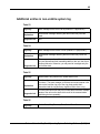
Stacking enhancement . . . . . . . . . . . . . . . . . . . . . . . . . . . . . . . . . . . . . . . . . . . . . . . . . 44
Faulty unit and cable detection . . . . . . . . . . . . . . . . . . . . . . . . . . . . . . . . . . . . . . . 44
Additional entries in volatile system log . . . . . . . . . . . . . . . . . . . . . . . . . . . . . . . . . 45
. . . . . . . . . . . . . . . . . . . . . . . . . . . . . . . . . . . . . . . . . . . . . . . . . . . . . . . . . . . . . . . . 49
Additional entries in non-volatile system log . . . . . . . . . . . . . . . . . . . . . . . . . . . . . 49
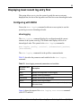
Displaying most recent log entry first . . . . . . . . . . . . . . . . . . . . . . . . . . . . . . . . . . . . . . 51
Configuring with NNCLI . . . . . . . . . . . . . . . . . . . . . . . . . . . . . . . . . . . . . . . . . . . . . 51
show logging . . . . . . . . . . . . . . . . . . . . . . . . . . . . . . . . . . . . . . . . . . . . . . . . . . 51
Latch or overwrite volatile RAM log file . . . . . . . . . . . . . . . . . . . . . . . . . . . . . . . . . 52
Enabling and disabling autosave . . . . . . . . . . . . . . . . . . . . . . . . . . . . . . . . . . . . . . . . . 53
Configuring with NNCLI . . . . . . . . . . . . . . . . . . . . . . . . . . . . . . . . . . . . . . . . . . . . . 53
show autosave command . . . . . . . . . . . . . . . . . . . . . . . . . . . . . . . . . . . . . . . . 53
215148-D
Contents
5
autosave enable command . . . . . . . . . . . . . . . . . . . . . . . . . . . . . . . . . . . . . . . 54
no autosave enable command . . . . . . . . . . . . . . . . . . . . . . . . . . . . . . . . . . . . 54
default autosave enable command . . . . . . . . . . . . . . . . . . . . . . . . . . . . . . . . . 54
Downloading image without resetting . . . . . . . . . . . . . . . . . . . . . . . . . . . . . . . . . . . . . 55
Configuring with NNCLI . . . . . . . . . . . . . . . . . . . . . . . . . . . . . . . . . . . . . . . . . . . . . 55
Using SNTP . . . . . . . . . . . . . . . . . . . . . . . . . . . . . . . . . . . . . . . . . . . . . . . . . . . . . . . . . 57
Configuring with NNCLI . . . . . . . . . . . . . . . . . . . . . . . . . . . . . . . . . . . . . . . . . . . . . 57
show sntp command . . . . . . . . . . . . . . . . . . . . . . . . . . . . . . . . . . . . . . . . . . . . 58
show sys-info command . . . . . . . . . . . . . . . . . . . . . . . . . . . . . . . . . . . . . . . . . 59
sntp enable command . . . . . . . . . . . . . . . . . . . . . . . . . . . . . . . . . . . . . . . . . . . 60
no sntp enable command . . . . . . . . . . . . . . . . . . . . . . . . . . . . . . . . . . . . . . . . 61
sntp server primary address command . . . . . . . . . . . . . . . . . . . . . . . . . . . . . . 61
sntp server secondary address command . . . . . . . . . . . . . . . . . . . . . . . . . . . 62
no sntp server command . . . . . . . . . . . . . . . . . . . . . . . . . . . . . . . . . . . . . . . . . 62
sntp sync-now command . . . . . . . . . . . . . . . . . . . . . . . . . . . . . . . . . . . . . . . . 63
sntp sync-interval command . . . . . . . . . . . . . . . . . . . . . . . . . . . . . . . . . . . . . . 63
Using DNS to ping and telnet . . . . . . . . . . . . . . . . . . . . . . . . . . . . . . . . . . . . . . . . . . . . 64
Configuring with NNCLI . . . . . . . . . . . . . . . . . . . . . . . . . . . . . . . . . . . . . . . . . . . . . 64
show ip dns command . . . . . . . . . . . . . . . . . . . . . . . . . . . . . . . . . . . . . . . . . . 65
ping command . . . . . . . . . . . . . . . . . . . . . . . . . . . . . . . . . . . . . . . . . . . . . . . . . 65
ip name-server command . . . . . . . . . . . . . . . . . . . . . . . . . . . . . . . . . . . . . . . . 67
no ip name-server command . . . . . . . . . . . . . . . . . . . . . . . . . . . . . . . . . . . . . 67
ip domain-name command . . . . . . . . . . . . . . . . . . . . . . . . . . . . . . . . . . . . . . . 68
no ip domain-name command . . . . . . . . . . . . . . . . . . . . . . . . . . . . . . . . . . . . . 69
default ip domain-name command . . . . . . . . . . . . . . . . . . . . . . . . . . . . . . . . . 69
Sample commands . . . . . . . . . . . . . . . . . . . . . . . . . . . . . . . . . . . . . . . . . . . . . 69
Changing HTTP port number . . . . . . . . . . . . . . . . . . . . . . . . . . . . . . . . . . . . . . . . . . . . 70
Configuring with NNCLI . . . . . . . . . . . . . . . . . . . . . . . . . . . . . . . . . . . . . . . . . . . . . 70
show http-port command . . . . . . . . . . . . . . . . . . . . . . . . . . . . . . . . . . . . . . . . 70
http-port command . . . . . . . . . . . . . . . . . . . . . . . . . . . . . . . . . . . . . . . . . . . . . 71
default http-port . . . . . . . . . . . . . . . . . . . . . . . . . . . . . . . . . . . . . . . . . . . . . . . . 71
Displaying MAC address table by port number . . . . . . . . . . . . . . . . . . . . . . . . . . . . . . 72
show mac-address-table command . . . . . . . . . . . . . . . . . . . . . . . . . . . . . . . . . . . . 72
Custom Autonegotiation Advertisements . . . . . . . . . . . . . . . . . . . . . . . . . . . . . . . . . . . 73
Unit replacement . . . . . . . . . . . . . . . . . . . . . . . . . . . . . . . . . . . . . . . . . . . . . . . . . . . . . 75
Release Notes for BayStack Operating System Switching Software (BoSS) 3.1
6
Contents
Replacing a unit in a stack . . . . . . . . . . . . . . . . . . . . . . . . . . . . . . . . . . . . . . . . . . . 75
Command Line Interface (CLI) commands for unit replacement . . . . . . . . . . . . . . 77
RADIUS fallback enhancement . . . . . . . . . . . . . . . . . . . . . . . . . . . . . . . . . . . . . . . . . . 77
RADIUS access challenge . . . . . . . . . . . . . . . . . . . . . . . . . . . . . . . . . . . . . . . . . . . . . . 78
Enhanced autotopology display . . . . . . . . . . . . . . . . . . . . . . . . . . . . . . . . . . . . . . . . . . 78
show auto-topology nmm-table command . . . . . . . . . . . . . . . . . . . . . . . . . . . . . . . 79
Display date of manufacture and HW deviation number in WEB/CLI/Console . . . . . . 80
50 addresses for IPMGR . . . . . . . . . . . . . . . . . . . . . . . . . . . . . . . . . . . . . . . . . . . . . . . 80
Restricted SSH access with IP Manager list . . . . . . . . . . . . . . . . . . . . . . . . . . . . . . . . 81
Telnet client support . . . . . . . . . . . . . . . . . . . . . . . . . . . . . . . . . . . . . . . . . . . . . . . . . . . 81
telnet command . . . . . . . . . . . . . . . . . . . . . . . . . . . . . . . . . . . . . . . . . . . . . . . . 81
Trap notification when configuration changes saved to NVRAM . . . . . . . . . . . . . . . . . 82
Displaying the default interface . . . . . . . . . . . . . . . . . . . . . . . . . . . . . . . . . . . . . . . . . . 82
User-based policies . . . . . . . . . . . . . . . . . . . . . . . . . . . . . . . . . . . . . . . . . . . . . . . . . . . 83
Configuring with NNCLI . . . . . . . . . . . . . . . . . . . . . . . . . . . . . . . . . . . . . . . . . . . . . 83
eapol user-based-policies enable command . . . . . . . . . . . . . . . . . . . . . . . . . . 83
no eapol user-based-policies enable command . . . . . . . . . . . . . . . . . . . . . . . 83
default eapol user-based-policies enable command . . . . . . . . . . . . . . . . . . . . 84
show eapol . . . . . . . . . . . . . . . . . . . . . . . . . . . . . . . . . . . . . . . . . . . . . . . . . . . 84
Related publications . . . . . . . . . . . . . . . . . . . . . . . . . . . . . . . . . . . . . . . . . . . . . . . . . . . 84
How to get help . . . . . . . . . . . . . . . . . . . . . . . . . . . . . . . . . . . . . . . . . . . . . . . . . . . . . . 85
215148-D
7
Introduction
These release notes document the new features and known issues of BayStack
Operating System Switching Software (BoSS), software release 3.1.
New features for BoSS, software release 3.1
These release notes contain information on the following new features for BoSS,
software release 3.1:
•
•
•
•
•
•
•
•
•
•
•
•
•
•
•
•
•
•
•
•
•
•
•
“ASCII configuration generator” on page 24
“802.3ad Link Aggregation” on page 30
“Enabling traffic separation” on page 32
“Defaulting to BootP-when-needed” on page 33
“Layer-2 restricted filters” on page 35
“Layer-2 restricted QoS meters” on page 35
“IP/BootP configuration retention on downgrade” on page 37
“Copper GBIC support” on page 37
“Using remote logging” on page 37
“Syslog content enhancements” on page 42
“Syslog enhancements for SSH” on page 43
“Stacking enhancement” on page 44
“Displaying most recent log entry first” on page 51
“Enabling and disabling autosave” on page 53
“Downloading image without resetting” on page 55
“Using SNTP” on page 57
“Using DNS to ping and telnet” on page 64
“Changing HTTP port number” on page 70
“Displaying MAC address table by port number” on page 72
“Custom Autonegotiation Advertisements” on page 73
“Unit replacement” on page 75
“RADIUS fallback enhancement” on page 77
“RADIUS access challenge” on page 78
Release Notes for BayStack Operating System Switching Software (BoSS) 3.1
8
•
•
•
•
•
•
•
•
“Enhanced autotopology display” on page 78
“Telnet client support” on page 81
“Display date of manufacture and HW deviation number in WEB/CLI/
Console” on page 80
“50 addresses for IPMGR” on page 80
“Restricted SSH access with IP Manager list” on page 81
“Trap notification when configuration changes saved to NVRAM” on page 82
“Displaying the default interface” on page 82
“User-based policies” on page 83
Hardware compatibility matrix
BoSS for Policy Switches Software Version 3.1 is compatible with the switches
listed in Table 1.
Table 1 Hardware platform and part numbers for BayStack switches
Hardware Platform
Part Number
BayStack 460-48T-PWR
AL2001?20
BayStack 470-24T
AL2012?37
BayStack 470-48T
AL2012?34
BayStack BPS
AL2001?15
The question mark(?) in the part numbers above may be replaced with the
appropriate letter from the table below to identify a particular power cord option.
Table 2 describes the power cord options and option codes for BayStack switches.
Table 2 Power cord options and option codes for BayStack switches
Power cord option description
215148-D
Option Code
No power cord
A
European Union power cord
B
UK power cord
C
Japan power cord
D
9
Table 2 Power cord options and option codes for BayStack switches (continued)
Power cord option description
Option Code
North American power cord
E
Australia power cord
F
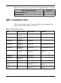
GBIC compatibility matrix
Table 3 lists the Gigabit Interface Converters (GBICs) that are supported by the
BoSS for Policy Switches Software Version 3.1.
Table 3 GBIC compatibility matrix
GBIC
Standard or SFP
Order number
Comment
1000Base-T Copper
Standard (RJ-45
connector)
AA1419042
BayStack 470 Only
1000Base-SX
Standard (SC
connector)
AA1419001
1000Base-LX
Standard (SC
connector)
AA1419002
1000Base-XD
Standard (SC
connector)
AA1419003
Extended distance 50km
1000Base-ZX
Standard (SC
connector)
AA1419004
Extended distance 70km
1000BaseWDM
Standard (SC
connector)
From AA1419017 to
AA1419024
1470nm-1610nm (in 20nm
intervals)
1000Base-SX
SFP (LC connector)
AA1419013
1000Base-SX
SFP (MT-RJ
connector)
AA1419014
1000Base-LX
SFP (LC connector)
AA1419015
1000Base-CWDM
(40km)
SFP (LC connector)
From AA1419025 to
AA1419032
1470nm - 1610nm (in 20nm
intervals)
1000Base-CWDM
(70km)
SFP (LC connector)
From AA1419033 to
AA1419040
1470nm - 1610nm (in 20nm
intervals)
Release Notes for BayStack Operating System Switching Software (BoSS) 3.1
10
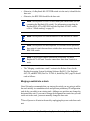
BayStack 450 support
BoSS Software Version 3.1 supports stacks that contain BayStack 450 switches.
•
•
The BayStack 450 units must run BayStack 450 Software Version 4.4.0.6.
The BayStack 450 units cannot be stacked with the BayStack 470-48T.
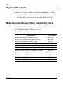
Media Dependant Adapter (MDA) compatibility matrix
Table 4 lists the MDAs that are supported in the BayStack BPS and the BayStack
460-24T-PWR running BoSS Software Version 3.1.
Table 4 MDA compatibility matrix
MDA description
215148-D
Order number
450-1SX 1-port 1000BASE-SX Single PHY MDA
AL2033005
450-1SR 1-port 1000BASE-SX Redundant PHY MDA
AL2033006
450-1LX 1-port 1000BASE-LX Single PHY MDA
AL2033007
450-1LR 1-port 1000BASE-LX Redundant PHY MDA
AL2033008
BayStack 450-1 GBIC MDA
AL2033009
BPS2000-4TX 4-port 10/100 MDA
AL2033011
BPS2000-4FX 4-port 100BASE-FX MDA w/mini MT-RJ-type
connectors
AL2033012
BPS2000-2FX 2-port 100BASE-FX MDA w/SC-type connectors
AL2033013
BPS2000 1 port 1000BASE-T MDA
AL2033014
BPS2000 2port 1000BASE-T MDA
AL2033015
BPS2000 2 port SFP GBIC MDA
AL2033016
11
Software compatibility matrix
BoSS Software Version 3.1 for Policy switches compatibility
matrix
The components for the BoSS Software Version 3.1 are:
•
•
•
•
•
•
•
BoSS Standard Runtime Image Software Version 3.1.0.78 (boss31078.img)
BoSS Secure Runtime Image Software Version 3.1.0.79 (boss31079s.img)
BoSS Boot/Diagnostic Software Version 3.0.0.5 (boss3005_diag.bin)
Java Device Manager software version 5.7.6.0 (jdm_5760)
BoSS Management Information Base (MIB) definition files
(bossmibs_3.1.0.52.zip)
BayStack 450 Software Version 4.4.0.6
BayStack 460-24T-PWR PoE Software v2.3.0 (bs4607013_002.poe.zip)
BoSS software version 3.0 for Policy switches compatibility
matrix
The components for the BoSS Software Version 3.0 are:
•
•
•
•
•
•
•
BoSS Standard Runtime Image Software Version 3.0.0.54 (boss30054.img)
BoSS Secure Runtime Image Software Version 3.0.0.55 (boss30055ss.img)
BoSS Boot/Diagnostic Software Version 3.0.0.4 (boss3004_diag.bin)
Java Device Manager Version 5.5.6.0 (jdm_5560)
BoSS Management Information Base (MIB) definition files
(bossmibs_v3.0.0.38.zip)
BayStack 450 Software Version 4.2.0.22
BayStack 460-24T-PWR PoE Software v2.3.0 (bs4607013_002.poe.zip)
Known issues for BoSS, software version 3.1
BoSS, software version 3.1 has the following known issues:
Release Notes for BayStack Operating System Switching Software (BoSS) 3.1
12
•
•
•
•
•
•
•
•
•
•
•
•
215148-D
Device Manager and Web-based management do not include help information
for the new 3.1 features.
When in mixed stack mode, the user interface does not provide the ability to
configure the BayStack 450 to filter unregistered frames. This feature is only
available on the BayStack 450 when not stacked with the BayStack BPS,
BayStack 470, and BayStack 460. (Q00707465)
The software will allow you to remove the Management VLAN from all
spanning tree groups, even though this configuration should be avoided.
(Q00723332)
Downloading the configuration file from the TFTP server may fail with an
“Intra-stack communication” error. Simply re-attempt the configuration file
download should this occur. (Q00725148)
When a tagged port is part of multiple Spanning Tree Groups, that port should
be configured to tag all traffic using the tagAll option. (Q00728620)
If you have the Secure Shell (SSH) feature enabled and you upgrade your
stack or switch to BoSS Software Version 3.1, the SSH feature will be
disabled. (Q00838995)
ASCII Configuration File download is not supported through an Secure Shell
(SSH) session. (Q00840035)
Downloading binary configuration files, ASCII configuration files, and
software image files is not supported when a stack is in a temporary base-unit
condition. (Q00840624)
If you are managing the stack via a console cable connection, the download
command with the no-reset option may only be executed from the base unit’s
console port. (Q00841927)
After you download an image file using the "download no-reset" option, you
must reset the switch or stack before executing subsequent downloads.
(Q00841945)
You may not execute the lacp clear-stats against all ports in a stack
simultaneously. You may execute the command against all the ports in a
switch simultaneously, and then against each switch in a stack. (Q00844967)
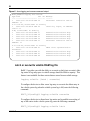
When you create an MLT group using the Menu Interface, you must identify a
unit number/port number combination in the first field in order for the port
configuration to be accepted by the Menu Interface, as shown. For example:
13
Trunk
----1
2
3
4
5
6
•
•
•
•
•
•
•
Trunk Members
------------------------------[ /1 ][ / 2][ /3 ][ / ] [
[ 2/6 ][ 2/7 ][ / ][ / ] [
[ 3/10 ][ 4/11][ 4/12][ 5/13] [
[ /
][ / ][ / ][ / ] [
[ /
][ / ][ / ][ / ] [
[ /
][ / ][ / ][ / ] [
STP Learning
Trunk Mode
Trunk Status
------------ --------------- -----------Normal
]
Basic
[ Disabled ]
Normal
]
Basic
[ Disabled ]
Normal
]
Basic
[ Disabled ]
Normal
]
Basic
[ Disabled ]
Normal
]
Basic
[ Disabled ]
Normal
]
Basic
[ Disabled ]
Ensure you assign an IP address to the switch or stack before enabling
RADIUS authentication. If you attempt to enable RADIUS authentication
using the CLI, you will not receive an error message even if the switch or
stack is not configured with an IP address. (Q00752827)
You may delete the IP address of the device using the CLI even if RADIUS
authentication is enabled and you will not receive an error message.
(Q00752828)
You may see the MAC address table refresh by itself every few seconds after
another unit in the stack has been reset. This condition may persist for one or
two minutes. (Q00761481)
You may only change the VLAN port configuration for MLT or DMLT ports
using the lowest numbered port in the MLT. (Q00761593)
The switch continues to send BootP request even after BootP is disabled.
(Q00763866)
If the Spanning Tree Protocol (STP) is enabled on a Link Aggregation Group
(LAG), then the LAG is subject to STP convergence, just like any other port.
If Spanning Tree does reconverge, you should expect there to be a loss of data
on the LAG link. (Q00769684, Q00804961)
There is an error on page 258 of the document, “Using the BayStack 470-24T
10/100/1000 Switch, Software Version 3.0” regarding how GBIC ports relate
to the various queues. The new text for the page is as follows:
The cascade port has a set of 2 queues that are serviced using an absolute
priority discipline. Filters are installed only on cascade ports that are
connected to BayStack 450 or BayStack 410 units in the stack.
BayStack 470-24T ports are associated with three types of queue sets:
•
•
Queue set 1 has four queues. The first queue is serviced in an absolute
priority fashion. The other three queues are serviced in a WRR fashion.
Queue set 2 has two queues that are serviced in an absolute priority
fashion.
Release Notes for BayStack Operating System Switching Software (BoSS) 3.1
14
•
Queue set 3 has eight queues. The first queue is serviced in an absolute
priority fashion. The other seven queues are serviced in a WRR fashion.
There are 3 sets of external ports that correspond to the queue sets. The first
set of external ports contains the 10/100 Mb/s ports. These interfaces are
associated with queue set 1. Each port in this set has a set of 4 queues. The
first queue holds the highest priority and is serviced in an absolute priority
fashion, meaning that this queue is serviced first until all the queued packets
are transmitted. The other three queues are serviced using a WRR scheduler.
The second set of external ports contains the cascade ports. These interfaces
are associated with queue set 2, which has 2 queues that are serviced in an
absolute priority fashion.
The third set of external ports contains the GBIC ports; these interfaces are
associated with queue set 3. Each port in this set has a set of 8 queues. The
first queue holds the highest priority and is serviced in an absolute priority
fashion, meaning that this queue is serviced first until all the queued packets
are transmitted. The other seven queues are serviced using a WRR scheduler.
You cannot change the characteristics of these queue sets (such as the service
discipline, packet or buffer thresholds, and queue weights for WRR
scheduler). (Q00770815)
•
In the Release Notes for the BayStack operating System Switching Software
(BoSS) 3.0 for BayStack 460, 470, and BPS 2000, Part No. 215148-A, dated
May 2003, page 20, the text should read:
The base unit in an allied stack cannot be a BPS 2000. Any of the other
BayStack Policy Switches can function as a base unit in an allied stack, but if
a BayStack 470-48T switch is in the stack, it must be the base unit.
•
The "Base unit for a mixed stack" section in the Release Notes for the
BayStack operating System Switching Software (BoSS) 3.0 for BayStack
460, 470, and BPS 2000, Part No. 215148-A, dated May 2003, page 22 should
read as follows:
Base unit for a mixed stack
In order of preference, one of the following switches can function as a base unit in
a mixed stack:
•
215148-D
If a BayStack 470-24T switch is in the stack, it should be the base unit.
15
•
•
Otherwise, if a BayStack 460-24T PWR switch is in the stack, it should be the
base unit.
Otherwise, the BPS 2000 should be the base unit.
Note: The BayStack 470-48T switch cannot join a mixed stack (or one
containing the BayStack 450 switch). For information on stacking the
BayStack 460, 470 or BPS 2000 with the BayStack 470-48T switch,
refer to "Allied stacking" on page 21.
Note: The BayStack 450 switch can never be the base unit of a stack.
Note: The BayStack 460 and BayStack 470 switches are the preferred
base units of a stack because these switches have more memory than the
BPS 2000 switch.
Note: A mixed stack cannot contain both a BayStack 450 and a
BayStack 470-48T unit. You also cannot have more than 8 units in a
stack.
•
The "Merging a switch into a stack" section in the Release Notes for the
BayStack operating System Switching Software (BoSS) 3.0 for BayStack
460, 470, and BPS 2000, Part No. 215148-A, dated May 2003, page 24 should
read as follows:
Merging a switch into a stack
Nortel Networks recommends that you start up the switch you are going to add to
the stack initially in a standalone mode and perform preliminary IP configuration
tasks before you add it to an existing stack. Adding a new unit does not change the
designated base unit. If you want to change the designated base unit when you add
a new unit to the stack, you must manually change the base unit:
7 Turn off power to all units in the stack by unplugging the power cords from each
unit.
Release Notes for BayStack Operating System Switching Software (BoSS) 3.1
16
a Add the new unit to the stack leaving the original base unit unchanged.
Do not change the base unit switches on the back.
b Power up the stack so that the new unit can learn the IP configuration
and stack information. Verify the configuration of the stack.
c Turn off power to all units in the stack by unplugging the power cords
from each unit.
d Change the base unit selector switch on the new unit so that it is now
base unit.
e Change the base unit selector switch on the original base unit so that it is
not longer configured as the base unit.
8 Power-up the newly joined units by plugging in the power cords and verify the
configuration. It may take a few minutes for the entire stack to display on the
console. All units will display as their new numbers within the newly formed
stack.
If you are running a pure stack that consists of only BPS2000s, and you add a
BayStack 460, a BayStack 470-24T switch, or a BayStack 470- 8T switch to
create an allied stack, you must manually change the base unit from a BPS
2000 switch. (Q00725300)
•
The CLI command "default duplex" may not be executed against a
GBIC port. If you execute this command against a GBIC port, you may see
the following error:
% Cannot modify settings
% inconsistentValue <port_number>
(Q00779732)
•
•
•
•
215148-D
When using LAG, a maximum of one standby link is supported. (Q00783242)
The ports on the BPS2000 2GT MDA may not be the target of the interface
"flowcontrol" command. Changing the flow control of the ports on the
BPS2000 2GT will result in autonegotiation being disabled on the port which
is an unsupported configuration. (Q00787182)
LAG / IGMP stream does not failover immediately when standby is present.
(Q00804064)
You must enable IGMP proxy when using IGMP in conjunction with LAG or
MLT. (Q00805627)
17
•
If you initiate a management session with the device through the console port,
you may see the following message in your system log.
session opened from 127.0.0.1
127.0.0.1 is the loopback address and this message is appropriate since the
connection was physically initiated from the console port on the device.
(Q00826743)
•
•
•
The CLI command "show running-config" will display the
configuration parameters that are appropriate for the user that is logged into
the device. A subset of the configuration parameters is displayed to the
READ-ONLY (RO), while a more verbose set of parameters is available to the
READ-WRITE (RW) user. (Q00827993)
Changes to the "cmd-interface" command will take effect when the user
next logs into the device. (Q00829147)
When using TFTP Transfers and a file not found error occurs you may see the
following error message on the console screen:
Error code 1: File not found
You may ignore this error message. (Q00726506)
•
•
•
•
•
•
•
•
Managing a LAG from a BayStack 450 in a mixed stack is not supported.
(Q00750550)
BPS/460-Changing from 10MB to 100 MB may result in port remaining in a
down condition (Q00630821)
MLT / LAG console menu screen may display more port members when
moving cables. Refresh the screen should this occur. (Q00770784)
You may not configure the rate-limiting feature for a standalone unit through
the CLI. Please configure this feature through the Web or the Menu Interface
(Q00853102).
When configured in a BayStack 450, the speed and duplex setting on the
BPS2000-4TX MDA, port 25 may change after soft reset (Q00585849)
No trap is sent after a BPS2000 unit which goes down and then comes back up
(Q00691410)
You cannot use Device Manager to download a binary configuration file. Use
the console, Web-based management, or Command Line interface.
(Q00689710)
On the BayStack 450 in a mixed stack configuration, make sure that you
re-enable Global Security when you make any changes to the security
parameters to ensure that the changes take effect. (Q00620973)
Release Notes for BayStack Operating System Switching Software (BoSS) 3.1
18
•
As part of your risk management protocol, please make sure you periodically
backup your configuration file. Binary configuration files may be used in
conjunction with the Unit Replacement Feature to increase network
availability. (Q00593649), (Q00604762), (Q00518226)
IGMP issues
•
•
•
IGMP reports may appear to be associated with several VLANs. This display
issue does not affect IGMP functionality or performance. (Q00623137)
When using BoSS 3.0, with IGMP enabled, in conjunction with the Passport
1200, make sure that the IGMP Proxy parameter is enabled on the BoSS 3.0
unit. This is due to an issue with the Passport 1200. (Q00591972)
When displaying the number of IGMP hosts on a stack, the number of hosts
displayed may be 20 to 25 percent of the actual count. You may determine the
actual count of IGMP hosts in the stack by interrogating each of the units in
the stack. (Q00626413)
Stack issues
•
•
•
Managing a stack through the console port of a BayStack 450 is not supported
in this release. Please use the console port of the base unit. (Q00605113,
Q00615550)
The Port IfIndex allocates resources for thirty-two ports per unit on a hybrid
stack and sixty-four ports per unit on a non-hybrid stack. Therefore, on a
hybrid stack IfIndex ports 1-32 are assigned to unit 1, ports 33-64 are assigned
to unit 2, ports 65-96 are assigned to unit 3, and so one. On a non-hybrid
stack, IfIndex ports 1-64 are assigned to unit 1, ports 65-128 are assigned to
unit 2, ports 129-192 are assigned to unit 3, and so one. (Q00606591)
Occasionally, in order for a stack to reform, the entire stack must reset. This
may happen when BayStack 450 is power cycled while in the stack.
(Q00607599)
DMLT issues
•
215148-D
Traffic flow will be interrupted on DMLT for around 30 seconds if a BayStack
450 contains one of the links that is reset when the switch loses power.
(Q00606295)
19
Nortel Networks Command Line Interface (NNCLI) issues
•
•
•
The "show stack-info uptime" command does not display the uptime
for BayStack 450 Switches. (Q00587447)
If you enable port mirroring on a port that has STP enabled, when you disable
port mirroring, you must manually re-enable STP support for that port.
(Q00617551)
You cannot change STP bridge priority, port priority, or path cost using the
console interface. Use the NNCLI, web-based management, or Device
Manager. (Q00592138)
Device Manager (DM) issues
•
•
•
•
When using Device Manager, the "UndersizePkts" count is not updated for
the BPS2000 1000MB MDAs. This statistic may be obtained through the
Console Interface menu system, the Nortel Networks Command Line
Interface, or the Web Interface. (Q00608569)
The MAC address security parameter "AuthCtlPartTime" is not supported
through Device Manager. Use the NNCLI or the Web Interface to set this
parameter. (Q00623812)
Device Manager will not identify the ports that have STP disabled on the
“STP->Ports” screen. Use the NNCLI or Web Interface to set this parameter.
(Q00607218)
When managing a BayStack 450 switch using Device Manager, it may take up
to 20 seconds for the unit to become editable after the edit menu option is
invoked. (Q00607328)
Web Interface issues
•
When using the Web interface, the version number of the software shown in
"Stack info > System Description" may be truncated. Use the NNCLI to query
the software version number. (Q00597301)
EAPoL issues
•
On BayStack 450 software version 4.2.0.22, the EAPoL Reauthentication
parameter is not supported.
Release Notes for BayStack Operating System Switching Software (BoSS) 3.1
20
Spanning Tree Protocol (STP) issues
•
In a stack with a large number of units (e.g. 6 to 8), a large number of VLANs
AND a large number of Spanning Tree Groups (STGs), STG configurations
may fail to be propagated to the most distant units in the stack. This issue only
affects non-default STGs (i.e. STG IDs not equal to 1). When this issue is
being experienced, ports on a unit in the stack will fail to send out BPDUs for
any affected non-default STGs. Ports on other units in the stack which belong
to this same STG may still correctly carry out the tasks of the STP.
A soft reset of an affected unit will cause the STG configuration information
to be re-acquired from the base unit and will correct this problem.
QoS issues
•
When specifying an IP filter to a particular destination, if there are two or
more filters, the source address must specify a particular host. (Q00599978)
Resolved issues for BoSS, software version 3.1
The following issues were resolved in software version BoSS 3.1:
•
•
•
•
•
•
When a port is administratively disabled, the port will no longer provide link
pulses. (Q00776905)
When configured in a BayStack BPS or BayStack 460, the speed and duplex
setting on the BPS2000-4TX MDA, port 25 no longer changes after soft reset
(Q00585849)
When using the unit replacement feature, you may now change the Target
Unit if you have 2 open telnet sessions. (Q00691669)
When using the unit replacement feature, you may now clear the target unit on
the renumber screen on all units, not just the base unit. (Q00696227)
IP address on the ping field now displays on all units of the allied stack, not
just the base unit. (Q00692114)
Do not enter the following characters in the MAC Security Port list:
- [+, - or , ]
These characters might cause the switch to stop operating properly in the
stack. (Q00637930)
215148-D
21
•
•
•
•
•
•
•
•
•
•
•
•
If you add MAC addresses to Security Lists that do not have ports associated
with them, and then display the Security Lists, the lists will appear empty
until a port is associated with the list. (Q00622842)
A mixed stack may reset twice after being booted or rebooted. This may cause
a slight delay in booting the stack. (Q00617280)
If you disable all Link up and down traps on the front panel interfaces, you
may still see link up traps reflecting the fact that cascade ports are initializing.
(Q00628942)
A BPS 2000 hangs when it receives an EAP access reject from an ACS radius
server. The problem appears very quickly if you retrieve a show command
from the CLI. For example: show int or show EAPoL. (Q00666030)
The EAPoL configuration parameter "Maximum Requests" has no effect.
The unit will only send out three EAP-Request/Identity frames before sending
a Failure frame and restarting the authentication process. (Q00637063)
When you download the DSA Authorization key for the first time, the transfer
may time out. Simply re-initiate the key download sequence. (Q00626440)
After rebooting the system, the Last key transfer result is not displayed
correctly. The display shows "Other: Error 0.", but the DSA-Key works
properly. (Q00597567)
It may take up to 10 minutes for the DSA key to be generated, and you will
not receive a message when the generation is completed. You cannot
authenticate an SSH session to a switch using the DSA key authentication
until the key has been fully generated. (Q00627029)
For port mirroring, all packets are sent to the monitor port after SSH has been
enabled and the stack has been rebooted. (Q00605912)
If the DSA public key download fails, the following message will be
displayed if the action was initiated through the console port: "Cannot
modify settings, Undo Failed 1." No message is displayed if the
action was initiated through telnet, but the following message will appear in
the last transfer results of the "show ssh download" command:
"Other: Error 5." (Q00578979)
You cannot enable SSH while the DSA public key is being generated. If you
attempt to enable SSH during the key generation period, you may see the
following error: "cannot modify settings." (Q00626985)
If you have a DMLT configured, and one of the units that has a configured
link fails, the NNCLI displays the link as belonging to port yy. For example:
2/yy. (Q00624397)
Release Notes for BayStack Operating System Switching Software (BoSS) 3.1
22
•
•
•
•
•
•
•
•
•
•
215148-D
Autotopology packets will not be transmitted on a link that is connected to a
DMLT if the unit is reset. Autotopology packets will continue to be received
from the units in the stack that were not reset. (Q00633687)
If you enter an incorrect password while using RADIUS authentication to
restrict management access to the device, the following error message
appears: "no response from RADIUS servers". (Q00560496)
In a hybrid stack, when the base unit fails and the temporary base units takes
over management responsibilities for the stack, the MAC address table cannot
be displayed through the NNCLI. The web interface will show the proper
information. (Q00637611)
In the NNCLI, changing the STP participation for all ports also changes the
MLT STP settings. Use the console or web-based management interface
instead of the NNCLI. (Q00598466)
When adding a user with privacy, the NNCLI does not allow you to omit the
write-view and specify the notify-view. The NNCLI requires that you enter a
read-view, write-view, and notify-view. If you do not wish to enter a
write-view for the user, you may use the web interface to create the user.
(Q00636313)
You cannot use the NNCLI to delete an SNMP v3 trap destination entry that
was created using the web interface or Device Manager. (Q00622221)
If you clear the log using the NNCLI "clear logging" command in a
stack of 8 units, the entries related to unit 8 may not be removed.
(Q00625617)
When using Device Manager, and changing information on multiple ports, the
Device Manager may display a message that the application is in "fetching
mode." If this message appears for more than a few seconds, Device Manager
application must be restarted. To avoid this error condition when using Device
Manager, do not attempt to change the configuration of more than a few ports
at a time. (Q00614887)
In a stacked configuration, after creating a new Spanning Tree Group (STG)
using Device Manager, the stgid may return a value of "0" when you attempt
to add a VLAN to the STG. Refresh the view of the stack and the stgid
parameter will return the correct value. (Q00584031)
You may encounter problems using Internet Explorer to access help items in
the right-hand frame of the online help screen. To avoid this problem, access
the help items you want through the Table of Contents in the left-hand frame
of the online help. (Q00561521)
23
•
•
•
•
Using the Web Interface, you may only change the EAPoL Re-Authentication
Field for individual ports. As a workaround, you may use the Console
Interface menu system, or the NNCLI. (Q00636903)
Using the Web interface, you cannot configure flow control for BS450 in a
mixed stack. Use the NNCLI or console interface. (Q00628278)
When using SNMP V3, you may only assign a notify-view address to one
user. You may not use the same target IP address for multiple users.
(Q00615644)
During the download process, the console may appear to hang. You can verify
that the download is in progress by the state of the LEDs. You may see the
following error message:
% error accessing image file
but the download will continue. (Q00596530)
•
•
•
•
You cannot disable port mirroring through the console interface. Use another
interface. (Q00620633)
If you default a unit and re-enter the same IP station addresses that were in the
ARP table, you may not be able to manage the switch. Either manage the
switch from another station, or reboot the stack. (Q00565566)
The ShapingQDrops parameter is not supported in Device Manager for the
BayStack 470 switches. (Q00647900)
There may be STP convergence issues with Multilink Trunking when there is
an STP priority/port path cost change, with uplink to the 8600. To correct this
problem, disable and re-enable MLT. (Q00604730).
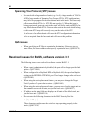
Downloading BoSS 3.1 software
To obtain the BoSS 3.1 software that does not contain SSH, download the
following files from the Nortel Networks customer support web site at:
http://www.nortelnetworks.com/support
•
boss31078.img
Note: Ensure that you do not interrupt the download process; do not
detach either the power cord or any of the network connections during
download.
Release Notes for BayStack Operating System Switching Software (BoSS) 3.1
24
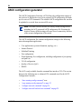
ASCII configuration generator
The ASCII Configuration Generator (ACG) allows the configuration settings of
the switch to be displayed or saved to an external ASCII configuration file made
up of a series of CLI commands. This editable ASCII configuration file can then
be uploaded to a switch from an external file server.
Note: You must reset the switch to the factory default settings before
uploading the ACG-generated ASCII configuration file. Resetting the
switch to factory default settings will cause loss of connectivity and loss
of the current configuration of the switch.
The ASCII configuration file contains configuration settings for the following
network management applications:
•
•
•
•
•
•
•
•
Core applications (system information, topology, etc.)
Internet Protocol
Multilink Trunking
Port configuration
Partial Spanning Tree configuration, including configuration of port priority
and path cost
VLAN configuration
Quality of Service (QoS)
RMON
The ACG is only available from the command line interface (CLI). This section
discusses the following new or enhanced CLI commands used for the ASCII
Configuration Generator:
•
•
•
•
215148-D
“show running-config command,” next
“copy running-config command” on page 25
“configure network command” on page 26
“configure network load-on-boot command” on page 29
25
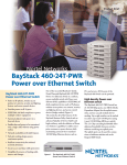
show running-config command
The show running-config command displays the current running
configuration. The syntax for the show running-config command is:
show running-config
The show running-config command is in the privExec command mode.
Note: The show running-config command is available, but its use
is restricted, when a user has read-only access.
The show running-config command has no parameters or variables.
Figure 1 displays sample output from the show running-config command.
Figure 1 show running-config command output
BS470#show running-config
enable
config t
mac-address-table aging-time 300
autotopology
snmp-server authentication-trap enable
snmp-server contact “SysAdmin”
snmp-server name “BS470”
snmp-server location “Lab”
snmp-server community “public” ro
snmp-server community “private” rw
--More--
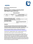
copy running-config command
The copy running-config command stores the current configuration as an
ASCII file on the TFTP server. The syntax for the copy running-config
command is:
copy running-config tftp [address <A.B.C.D>] filename <WORD>
Release Notes for BayStack Operating System Switching Software (BoSS) 3.1
26
Note: The copy config command will copy a binary configuration
file to the TFTP server. To store the configuration as an ASCII file, you
must use the copy running-config command.
The copy running-config command is in the privExec command mode.
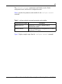
Table 5 describes the parameters and variables for the copy running-config
command.
Table 5 copy running-config command parameters and variables
Parameters and variables
Description
address <A.B.C.D>
Specifies the TFTP server IP address; enter in
dotted-decimal notation.
filename <WORD>
Specifies the name of the existing ASCII configuration file
on the TFTP server. This file must be read/write enabled.
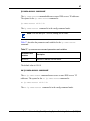
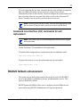
Figure 2 displays sample output from the copy running-config command.
Figure 2 copy running-config command output
BS470#copy running-config tftp address 134.177.118.56 filename config.txt
%Contacting TFTP host: 134.177.118.56.
%ACG Configuration file successfully written.
BS470#
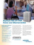
configure network command
The configure network command loads the ASCII configuration file from an
external TFTP server. The syntax for the configure network command is:
configure network [address <A.B.C.D>] [filename <WORD>]
215148-D
27
The configure network command is in the PrivExec mode, Global
configuration mode, and Interface configuration mode.
Table 6 describes the parameters and variables for the configure network
command.
Table 6 configure network command parameters and variables
Parameters and variables
Description
address <A.B.C.D>
Specifies the TFTP server IP address; enter in
dotted-decimal notation.
filename <WORD>
Enter the name of the ASCII configuration file you want to
copy from the TFTP server.
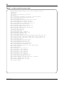
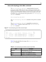
Figure 3 displays sample output from the configure network command.
Release Notes for BayStack Operating System Switching Software (BoSS) 3.1
28
Figure 3 configure network command output
BS470#configure network address 134.177.118.56 filename config.txt
Config File [|]
BS470#enable
Downloaded file successfully, executing . . .
BS470#config t
Enter configuration commands, one per line. End with CNTL/Z.
BS470(config)#mac-address-table aging-time 300
BS470(config)#autotopology
BS470(config)#snmp-server authentication-trap enable
BS470(config)#snmp-server contact “HCS lab”
BS470(config)#snmp-server community “public” ro
BS470(config)#snmp-server community “private” rw
BS470(config)#ip bootp server disable
BS470(config)#ip default-gateway 134.177.150.1
BS470(config)#ip address 134.177.150.79
BS470(config)#ip address netmask 255.255.255.0
BS470(config)#no auto-paid
% AutoPVID already disabled.
BS470(config)#vlan mgmt 1
BS470(config)#vlan name 1 “VLAN #1”
BS470(config)#vlan members remove 1 ALL
BS470(config)#vlan members 1 ALL
BS470(config)#vlan members 2 1-12
BS470(config)#$ed-frame disable filter-untagged-frame disable priority 0
BS470(config)#$ enable proxy enable robust-value 2 query-interval 125
BS470(config)#$ enable proxy enable robust-value 2 query-interval 125
BS470(config)#vlan mgmt 1
BS470(config)#spanning-tree priority 8000
BS470(config)#spanning-tree hello-time 2
BS470(config)#spanning-tree max-age 20
BS470(config)#spanning-tree forward-time 15
BS470(config)#interface FastEthernet ALL
BS470(config-if)#spanning-tree port 1-24 learning normal
BS470(config-if)#exit
BS470(config)#no mlt
BS470(config)#mlt 1 name “Trunk #1”
BS470(config)#mlt 2 name “Trunk #2”
BS470(config)#mlt 3 name “Trunk #3”
BS470(config)#mlt 4 name “Trunk #4”
BS470(config)#mlt 5 name “Trunk #5”
BS470(config)#mlt 6 name “Trunk #6”
BS470(config)#interface FastEthernet ALL
BS470(config-if)#no shutdown port 1-24
BS470(config-if)#snmp trap link-status port 1-24 enable
BS470(config-if)#speed port 1-24 auto
BS470(config-if)#duplex port 1-24 auto
BS470(config-if)#exit
215148-D
29
configure network load-on-boot command
The configure network load-on-boot command is used to configure the
switch to automatically download a configuration file when you reboot the switch.
The syntax for the configure network load-on-boot command is:
configure network load-on-boot {disable|use-bootp|
use-config} [address <A.B.C.D>] filename <WORD>
The configure network load-on-boot command is in the PrivExec mode, Global
configuration mode, and Interface configuration mode.
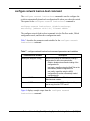
Table 7 describes the parameters and variables for the configure network
load-on-boot command.
Table 7 configure network load-on-boot command parameters and variables
Parameters and variables
Description
{disable|use-bootp|use-config}
Specifies the settings for automatically loading a
configuration file when the system boots:
• disable—disables the automatic loading of the
configuration file
• use-bootp—specifies using the BootP file as the
automatically loaded configuration file
• use-config—specifies using the ASCII
configuration file as the automatically loaded
configuration file
address <A.B.C.D>
Specifies the TFTP server IP address; enter in
dotted-decimal notation.
filename <WORD>
Enter the name of the ASCII configuration file you
want to copy from the TFTP server.
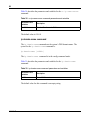
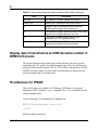
Figure 4 displays sample output from the configure network
load-on-boot command.
Release Notes for BayStack Operating System Switching Software (BoSS) 3.1
30
Figure 4 configure network load-on-boot command output
BS470#configure network load-on-boot use-config address 134.177.118.56 filename config.txt
BS470#
802.3ad Link Aggregation
Link Aggregation (LA) allows you to create and manage a trunk group. You can
control and configure a trunk group automatically through the use of the Link
Aggregation Control Protocol (LACP).
The LACP, defined by the IEEE 802.3ad standard, allows a switch to learn the
presence and capabilities of a remote switch by exchanging information with the
remote switch before a trunk group is formed. Either switch can accept or reject
the aggregation request with the far end on a per port basis. A link that can not join
a trunk group operates as an individual link.
802.3ad provides an industry standard method for bundling multiple links together
to form a single trunk between two networking devices. Trunks that conform to
the 802.3ad standard are Link Aggregation Groups (LAGs). BoSS 3.1 supports 2
types of trunks
•
•
Dynamic LAG
MLT
A trunk group that is formed by Link Aggregation is called a Link Aggregation
group (LAG), and a trunk group that is formed by BayStack Multilink Trunking is
called a Multilink trunk (MLT) group.
BayStack software supports both Link Aggregation groups and Multilink trunks.
By default Link Aggregation is set to disabled on all ports. A Link Aggregation
group or trunk group can be created or deleted automatically using Link
Aggregation Control Protocol (LACP).
The maximum number of Link Aggregation and MLT groups is 6, and the
maximum number of active links per group is 4. Link Aggregation allows more
than 4 links to be configured in one Link Aggregation group (LAG).
215148-D
31
The first four high priority links are active links and together they form a trunk
group. The fifth low priority link remains in standby mode. When one of the
active links goes down, the standby link becomes active and is added to the trunk
group. LACP supports only one standby link.
The failover process is as follows:
•
•
The down link is removed from the trunk group
The highest priority standby link is added to the trunk group.
There may be a temporary delay in traffic flow due to the switching of links. If the
active link goes down and there is no standby link, the traffic is re-routed to the
remaining active links with a minimal delay in time.
Half duplex links are not allowed in LAG, and all links in a LAG must have the
same speed.
802.3 Link Aggregation is available through the Nortel Networks Command Line
Interface (CLI). The CLI supports the following commands:
To enable, disable, or default LACP on a port:
•
•
•
lacp aggregation [port <portlist>] enable
no lacp aggregation [port <portlist>] enable
default lacp aggregation [port <portlist>] enable
To specify the LACP mode:
•
•
lacp mode [port <portlist>] {off | passive | active}
default lacp mode [port <portlist>]
To assign an administrative key value to a port:
•
lacp key [port <portlist>] <1-4095>
To specify the port priority:
•
•
lacp priority [port <portlist>] <0-255>
default lacp priority [port <portlist>]
Release Notes for BayStack Operating System Switching Software (BoSS) 3.1
32
To set port timeout:
•
•
lacp timeout-time [port <portlist>] {short | long}
default lacp timeout-time [port <portlist>]
To set LACP system priority:
•
•
lacp system-priority [0-65535]
default lacp system-priority
CLI Show commands for LACP:
•
•
•
•
•
•
•
•
show
show
show
show
show
show
show
lacp
lacp aggr
lacp port [<portList>]
lacp port aggregator
lacp debug member [portlist]
lacp system
lacp stats [port <portlist>]
lacp stats aggregator
clear-stats
Enabling traffic separation
Traffic separation is a feature used to separate IP packets and PPPoE packets from
an incoming port and forward them to different outgoing ports. IP packets and
PPPoE packets separated using this feature go to different channels. Hence, this is
packet-type based switching.
To enable this feature, use the following command:
config switch mode <l2|traffic-separation>
Note: Once this feature is enabled, port mirroring does not work. Also, QoS is
different from regular BPS2000 behavior.
215148-D
33
Defaulting to BootP-when-needed
The BootP default value is now BootP-when-needed. This allows you to boot your
switch and the system will automatically seek a BootP server for the IP address.
Note: If an IP address is assigned to the device and the BootP process
times out, the BootP mode remains the default mode of
BootP-when-needed.
However, if the device does not have an assigned IP address and the
BootP process times out, the BootP mode automatically changes to BootP
disabled. But this change to BootP disabled is not stored, and the BootP
reverts to the default value of BootP-when-needed after rebooting the
device.
When you upgrade, the switch retains the previous BootP value. When you default
the switch after the upgrade, the system moves to the default value of
BootP-when-needed.
Configuring with NNCLI
This section covers the following topics:
•
•
“ip bootp server command,” next
“default ip bootp server command” on page 35
ip bootp server command
The ip bootp server command configures BootP on the current instance of
the switch or server. You use this command if you want to change the value of
BootP from the default value, which is BootP when needed.The syntax for the ip
bootp server command is:
ip bootp server {always|disable|last|needed}
The ip bootp server command is in the config command mode.
Release Notes for BayStack Operating System Switching Software (BoSS) 3.1
34
Table 8 describes the parameters and variables for the ip bootp server
command.
Table 8 ip bootp server command parameters and variables
Parameters and
variables
Description
last|needed|disable| Specifies when to use BootP:
always
• always—Always use BootP
• disable—never use BootP
• last—use BootP or the last known address
• needed—use BootP only when needed
NOTE: The default value is to use BootP when needed.
215148-D
35
default ip bootp server command
The default ip bootp server command resets the mode to BootP when
needed, which is the default mode. The syntax for the default ip bootp
server command is:
default ip bootp server
The default ip bootp server command is in the config command mode.
The default ip bootp server command has no parameters or values.
Layer-2 restricted filters
The Layer-2 restricted filters feature allows you to configure up to 23 metered
policies. BoSS 3.1 supports both restricted and unrestricted meters.
Unrestricted meters
In BoSS Software versions prior to 3.1, only unrestricted meters were supported.
When using unrestricted meters, you may configure a maximum of 12 Layer-2
metered policies. This is because each metered policy requires a filter for
in-profile actions, and another filter for out-of-profile actions With 24 layer-2
filters available, and two filter for each metered policy, you end up with 12
Layer-2 metered policies.
Unrestricted meters may be applied to any group of interfaces: Trusted, Untrusted,
and Restricted.
Layer-2 restricted QoS meters
With restricted meters, you are allowed a maximum of 23 Layer-2 metered
policies. All 23 metered policies may have a different in-profile-action, but they
will all share the same out-of-profile action. The first policy created will consume
two filters; one filter is consumed for the in-profile action, and another filter is
Release Notes for BayStack Operating System Switching Software (BoSS) 3.1
36
consumed for the out-of-profile action. Subsequent restricted Layer-2 metered
policies will only use one filter for the in-profile-action and they will share the
out-of-profile action defined by the first filter. Since only one filter is used for
each policy, statistics will only count in-profile traffic.
Restricted meters can only be used when the Interface Class Restriction is set to
Unrestricted Only.
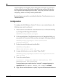
Configuration
To configure the BoSS Software Version 3.1 device to use restricted meters, the
following steps must be performed:
1
Ensure that the current Interface Class Restriction is set to Unrestricted Only
by entering the following CLI command.
BPS2000(config)# show qos agent
2
If the current Interface Class Restriction is not set to Unrestricted Only, you
may enable the Unrestricted Only mode by entering the following command:
BPS2000(config)# qosagent class-restrictions
unrestricted-only
3
Reboot the switch for this mode to take effect
BPS2000(config)#boot
Reboot the unit(s) (y/n) ? y
4
Assign a default action or use the default "Drop_Traffic"
BPS2000(config)# qosagent default-out-of-profile-action
name no-flow
5
Create the restricted meter
qos meter 1 create name myMeter committed-rate 5000
max-burst-rate 6000 restricted
Restricted meters are created when the "restricted" command argument is
appended to the "qos meter <meter_id> create" command.
6
215148-D
Apply the new restricted meter to a policy as you would an unrestricted meter.
37
IP/BootP configuration retention on downgrade
When downgrading a unit with BoSS Software for Policy Switches version 3.0.3
and later, the system will default all configuration, except for the following:
•
•
•
Stack operation mode
IP configuration
BootP mode
Previous releases of Policy Switch software retained the Stack Operational Mode
only on software downgrade. This change allows a remotely accessed switch to
maintain its accessibility after downgrade and/or not require the user re-enter this
basic information which should remained unchanged after a downgrade.
Copper GBIC support
A new full-sized GBIC is supported. This GBIC supports 1000BaseT and works
only on BayStack 470 units. For more information, see “GBIC compatibility
matrix” on page 9.
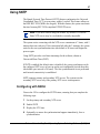
Using remote logging
This feature provides an enhanced level of logging by replicating system
messages onto a syslog server. System log messages from several switches can be
collected at a central location, which alleviates the network manager querying
each switch individually to interrogate the log files.
You must configure the remote syslog server and set up the unit to log
informational messages to this remote server. The UDP packet is sent to port 514
of the configured remote syslog server,
Once the IP address is in the system, you can send the syslog messages to the
remote syslog server. If a syslog message is generated prior to capturing the IP
address of the server, the system stores up to 10 messages that are sent once the IP
address of the remote server is on the system.
Release Notes for BayStack Operating System Switching Software (BoSS) 3.1
38
You configure this feature by enabling remote logging, specifying the IP address
of the remote syslog server, and specifying the severity level of the messages you
want sent to the remote server.
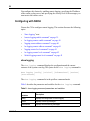
Configuring with NNCLI
You use the CLI to configure remote logging. This section discusses the following
topics:
•
•
•
•
•
•
•
•
“show logging,” next
“remote logging enable command” on page 39
“no logging remote enable command” on page 40
“logging remote address command” on page 40
“no logging remote address command” on page 41
“logging remote level command” on page 41
“no logging remote level command” on page 42
“default logging remote level command” on page 42
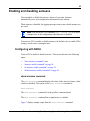
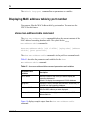
show logging
The show logging command displays the configuration and the current
contents of the system event log. The syntax for the show logging command is:
show logging [config] [critical] [informational] [serious]
[sort-reverse]
The show logging command is in the privExec command mode.
Table 9 describes the parameters and variables for the show logging command.
Table 9 show logging command parameters and variables
215148-D
Parameters and
variables
Description
config
Displays the configuration of event logging.
critical
Displays critical log messages.
informational
Displays informational log messages.
39
Table 9 show logging command parameters and variables
Parameters and
variables
Description
serious
Displays serious log messages.
sort-reverse
Displays log messages in reverse chronological order (beginning
with most recent).
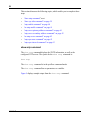
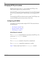
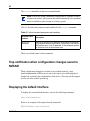
Figure 5 shows the output of the show logging config command.
Figure 5 show logging config command output
BS470_48>enable
BS470_48#show logging config
Event Logging: Enabled
Volatile Logging Option: Latch
Event Types To Log: Critical, Serious, Informational
Event Types To Log To NV Storage: Critical, Serious
Remote Logging: Disabled
Remote Logging Address: 0.0.0.0
Event Types To Log Remotely: None
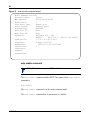
remote logging enable command
Note: The default value for remote logging is disabled
The logging remote enable command enables logging syslog messages to a
remote server. The syntax for the remote logging enable command is:
remote logging enable
The remote logging enable command is in the config command mode.
The remote logging enable command has no parameters or variables.
Release Notes for BayStack Operating System Switching Software (BoSS) 3.1
40
no logging remote enable command
The no logging remote enable command disables sending syslog messages
to a remote server. The syntax for the no logging remote enable command
is:
no remote logging enable
The no remote logging enable command is in the config command mode.
The no remote logging enable command has no parameters or variables.
logging remote address command
The logging remote address command sets the remote server for receiving
the syslog messages; you enter the IP address of the server you want. The syntax
for the logging remote address command is:
logging remote address <A.B.C.D>
The logging remote address command is in the config command mode.
Table 10 describes the parameters and variables for the logging remote
address command.
Table 10 logging remote address command parameters and variables
Parameters and
variables
<A.B.C.D>
Description
Specifies the IP address of the remote server in dotted-decimal
notation.
The default address is 0.0.0.0.
215148-D
41
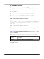
no logging remote address command
The no logging remote address command clears the IP address of the
remote server. The syntax for the no logging remote address command is:
no logging remote address
The no logging remote address command is in the config command mode.
The no logging remote address command has no parameters or variables.
logging remote level command
The logging remote level command sets the severity level of the logs you
send to the remote server. The syntax for the logging remote level
command is:
logging remote level {critical|informational|serious}
The logging remote level command is in the config command mode.
Table 11 describes the parameters and variables for the logging remote
level command.
Table 11 logging remote level command parameters and variables
Parameters and
variables
{critical|serious|
informational}
Description
Specifies the severity level of the log messages to be sent to the
remote server:
• critical
• informational
• serious
There is no default value for this command.
Release Notes for BayStack Operating System Switching Software (BoSS) 3.1
42
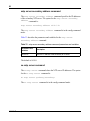
no logging remote level command
The no logging remote level command removes any severity level of the
log messages that you send to the remote server; it reverts to None. The syntax for
the no logging remote level command is:
no logging remote level
The no logging remote level command is in the config command mode.
The no logging remote level command has no parameters or variables.
default logging remote level command
The default logging remote level command sets the severity level of the
logs you send to the remote server to the default value, which is None. The syntax
for the default logging remote level command is:
default logging remote level
The default logging remote level command is in the config command
mode.
The default logging remote level command has no parameters or
variables.
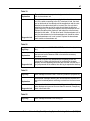
Syslog content enhancements
In addition to the syslog engine enhancements including in this release, several
new syslog events are generated and some existing events are enhanced:
•
•
•
215148-D
The Link Up/Down traps events now include unit and port number
information.
The Stack Cascade port link up/down events now clearly indicate the link
event is for a cascade port.
Agent and Diagnostics code upgrades generate a serious event which is
logged, by default, in the non-volatile syslog. The event text includes the
version if successful and the failure reason if the download fails.
43
•
•
•
SNTP sync events are logged on each sync attempt and pass/fail is indicated.
Telnet session open, close, and timeout (Inactivity logout) events are logged.
New event for the bsnConfigurationSavedToNvram trap. Generated when a
config change written to NVRAM.
Syslog enhancements for SSH
The following event-triggered messages have been added to the system log to
support SSH.
•
•
•
•
•
•
•
•
Success Connection—Indicates that the client has successfully initiated an
SSH session with the switch or stack
Connection Logout—Indicates that the client has logged out of the device
Inactivity Logout—Indicates that the client was logged out by the stack or
switch due to inactivity
Disallowed connection dues to host not allowed—Indicates that the client's
connection request was not allowed due to the restrictions applied by the IP
Manager Access Control List.
Download DSA key completion—Indicates that the switch or stack has
successfully downloaded the DSA key
SSH Enabled in secure mode—Indicates that the “ssh secure” command
was invoked to initiate the SSH feature. Telnet, SNMP, and Web management
are all disabled as a result of this command.
SSH Enabled in non-secure mode—Indicates that the “ssh” command was
invoked to initiate the SSH feature
SSH Disabled—Indicates that the SSH feature has been deactivated by the
“no ssh” command
Release Notes for BayStack Operating System Switching Software (BoSS) 3.1
44
Stacking enhancement
Faulty unit and cable detection
When the operation mode is pure, the stack manager can detect the scenario
whereby a unit appears good to its neighboring units (its up and downstream
clocks are good) but the data packets it transmits or receives are corrupted or
missing. In such a scenario, the stack falls apart and the ring check does not
succeed.
This triggers the “Ring Discovery” algorithm whereby units are polled both
downstream and upstream individually to isolate the point of failure. When the
failure is isolated, the bad unit or cables are wrapped out.
In the case where a cable has bad data pins, the stack ports where the cable is
connected are wrapped out. On a unit that has its IN port connected to the bad
cable, the system log shows “IN stack port wrapped; check for bad cable or unit”
and its downstream LED stays amber.
Similarly on the unit that has its OUT port connected to the bad cable, the system
log shows “OUT stack port wrapped; check for bad cable or unit” and its upstream
LED stays amber. When replacing a bad cable with a good one, at least one unit
should be rebooted so that the stack manager on the base unit detects a unit
coming in and re-runs the stack.
215148-D
45
Additional entries in volatile system log
Table 12
Log Entry
Multiple Base Units Detected, Check Base Unit Switch
Explanation
More than one unit has its "base unit switch" in the on position.
Diagnostic Info
Check to make sure only one unit has its "base unit switch" in the on
position.
Table 13
Log Entry
Multiple Base Units Detected in UNP Phase
Explanation
More than one unit has its "base unit switch" selected or there is a
contention in 2 units trying to be the base unit.
Diagnostic Info
Check to make sure only one unit has its "base unit switch" in the on
position
Table 14
Log Entry
Incompatible operational mode, module <physical id> failed to join
stack
Explanation
module <physical id> operation mode is not the same as the base
unit’s.
Diagnostic Info
Change the operation mode on the module <physical id> so that it is
the same as the operational mode of the base.
Table 15
Log Entry
Incompatible Software Revision, module <physical id> failed to join
stack
Explanation
module <physical id> software revision is not the same as the base
unit’s software revision.
Diagnostic Info
Program the same agent image on all units. All units should have the
same boss agent software revision and all Baystack 450 in the stack
should have the same software revision.
Release Notes for BayStack Operating System Switching Software (BoSS) 3.1
46
Table 16
Log Entry
Incompatible interop value, module <physical id> failed to join stack
Explanation
module <physical id> type cannot interoperate with the base unit’s
interop value.
Diagnostic Info
Replace module <physical id> with another module type that is
compatible with the base’s interop value.
Table 17
Log Entry
Incompatible operational mode, module inactive, module <physical
id> failed to join stack
Explanation
module <physical id> has transitioned to inactive state. When there is
a configuration change, the base unit will re-transmit the “UNP”
packet and a unit upon receiving it may find that it is no longer active
or in the stack.
Diagnostic Info
Find out why module <physical id> became inactive.
Table 18
Log Entry
IN stack port wrapped; check for bad cable or unit.
Explanation
The unit did not receive any acknowledgment when it communicates
with its upstream unit.
Diagnostic Info
First, determine whether you have a bad cable or a bad upstream
unit. If the cable connected to IN stack port is bad, the stack port on
both ends of the cable should be wrapped out and the units attached
to the cable should still be in stack. Also, the unit that is attached to
the other end of the cable should have the entry "OUT stack port
wrapped; check for bad cable or unit". Replace the cable with a good
one, and reboot the units that were attached to this cable.
On the other hand, if the upstream unit is bad, the downstream led on
the upstream unit should be amber and the upstream unit will not be
in stack. Replace the upstream unit.
Table 19
Log Entry
215148-D
OUT stack port wrapped; check for bad cable or unit.
47
Table 19
Explanation
The unit did not receive any acknowledgment when it communicates
with its downstream unit.
Diagnostic Info
First, determine whether you have a bad cable or bad downstream
unit. If the cable connecting to the OUT stack port is bad, the stack
port on both ends of the cable should be wrapped out and the units
attached to the cable should still be in stack. Also, the unit that is
attached to the other end of the cable should have the following
system log entry, "IN stack port wrapped; check for bad cable or unit".
Replace the cable with a good one, and reboot the units that were
attached to this cable. On the other hand, if the downstream unit is
bad, the downstream led on the downstream unit should be amber
and the downstream unit is not in stack. Replace the downstream
stack module or downstream unit.
Table 20
Log Entry
Stack manager event MODULE INACTIVE (module id = <physical
id>)
Explanation
Informational message declaring that the module < module mask>
has become inactive because it did not receive the necessary
heartbeat packets.
Diagnostic Info
You need to find out why heartbeats are not getting to this unit
<physical id>. Make sure that the unit is connected to the stack
properly and the cascading connectors are screwed in all the way. If
you just powered off the module, then this log is expected to show up.
Table 21
Log Entry
Stack manager event BECOME TEMP BU (module id <physical id>)
Explanation
Informational message declaring the unit has become the base unit
due to the heartbeat packets not being received from the former base
unit.
Diagnostic Info
Make sure that the former base unit is still operational. Typically,
when the base unit goes out for more than 30 seconds, a temporary
base unit will take over.
Table 22
Log Entry
Stack manager detected a unit coming up
Release Notes for BayStack Operating System Switching Software (BoSS) 3.1
48
Table 22
215148-D
Explanation
Informational message declaring that a unit in the stack is booting up.
Diagnostic Info
This is an informational message. A unit was just inserted or
rebooted in the stack. Make sure that you are not rebooting units
unnecessary.
49
Additional entries in non-volatile system log
Table 23
Log Entry
Stack manager event JOIN STACK (module id = <physical id>)
Explanation
Informational message declaring that the module has joined the
stack
Diagnostic Info
N/A
Table 24
Log Entry
Stack manager event LEAVE STACK (module id = <physical id>)
Explanation
Informational message declaring that the module has just left the
stack.
Diagnostic Info
This may or may not be a failure depending on the circumstances. If
you just disconnected both cascading cables on the unit, then this is
a normal behavior. Otherwise, you may need to investigate why the
unit left the stack.
Table 25
Log Entry
Switch Reset, Ring Check Error, Global Reset Count
Explanation
A soft reset has occurred when the global reset counter value is
<number>. The stack manager on the base unit reset because it did
not receive back the ring any of the ring check packet that it
transmitted and the ring discovery algorithm fails to form a ring.
Diagnostic Info
This event should not normally occur unless there have been multiple
resets of the units on the stack which result in the communication
path being broken repeatedly.
Table 26
Log Entry
Switch Reset, Ring Discovery Error, Global Reset Count
Release Notes for BayStack Operating System Switching Software (BoSS) 3.1
50
Table 26
Explanation
A switch soft reset has occurred when the global reset counter value
is <number>. The stack manager issue this soft reset the ring
discovery algorithm was not successful after 2 attempts.
Diagnostic Info
Check to make sure that there is no bad cable or unit. Make sure that
you are not resetting or disconnecting units while the ring discovery
algorithm is being executed.
Table 27
Log Entry
Switch Reset, UNP Error, Global Reset Count
Explanation
A switch soft reset has occurred at the specified global reset count.
The stack manager issued the reset because the non-base unit has
not received the upstream next neighbor packet after 2 UNP timer
timeouts.
Diagnostic Info
The unit is not receiving any UNP packet. It may be that the units are
being reset one after another during the boot up phase over an
interval of more than one minute. If this is not the case, make sure
that there is no bad cable or unit.
Table 28
Log Entry
Switch Reset, DbToken Not Received, Global Reset Count <value>
Explanation
A switch soft reset has occurred at the specified global reset count.
The stack manager issued the soft reset because the unit did not
receive the database token after 3 timer timeouts.
Diagnostic Info
This should not happen unless the user repeatedly reset units in the
stack without giving it a chance to join over a period of time.
Table 29
215148-D
Log Entry
Switch Reset, Db Xchg (got <hexadecimal value>, wanted =
<hexadecimal value) Global Reset Count <value>
Explanation
A switch soft reset has occurred at the global Reset Count. The stack
manager issued the soft reset because database exchanges did not
succeed for all applications. The missing bits in the got <
hexadecimal value> from the wanted <hexadecimal value> indicates
which applications were not successfully.
Diagnostic Info
N/A
51
Displaying most recent log entry first
This option allows you to view the system log with the most recent entry
displayed first; the rest of the log entries are listed in reverse chronological order.
Configuring with NNCLI
You use the show logging command (with sort-reverse option) to sort the
system log in reverse chronological order.
show logging
The show logging command displays the configuration and the current
contents of the system event log. The default value displays all levels in
chronological order. The syntax for the show logging command is:
show logging [config] [critical] [informational][serious]
[sort-reverse]
The show logging command is in the privExec command mode.
Table 30 describes the parameters and variables for the show logging
command.
Table 30 show logging command parameters and variables
Parameters and
variables
Description
config
Displays the configuration of event logging.
critical
Displays critical log messages.
informational
Displays informational log messages.
serious
Displays serious log messages.
sort-reverse
Displays log messages in reverse chronological order (beginning
with most recent).
Figure 6 shows the output of the show logging sort-reverse command
(with SNTP enabled).
Release Notes for BayStack Operating System Switching Software (BoSS) 3.1
52
Figure 6 show logging sort-reverse command output
BS470_48#show logging sort-reverse
Type Time
Idx Src Message
---- ----------------------- ---- --- ------I
2003-10-27 20:52:00 GMT 59
Successful connection from IP
address: 13
4.177.118.66, access mode: no security
I
2003-10-27 20:48:51 GMT 58
Inactivity logout, IP address:
134.177.11
8.66, access mode: no security
I
2003-10-27 20:26:03 GMT 57
Authentication Failure Trap
I
2003-10-27 20:25:03 GMT 56
Authentication Failure Trap
I
2003-10-27 20:24:03 GMT 55
Authentication Failure Trap
I
2003-10-27 20:23:03 GMT 54
Authentication Failure Trap
I
2003-10-27 20:16:00 GMT 53
Successful connection from IP
address: 13
4.177.118.66, access mode: no security
I
2003-10-27 19:32:06 GMT 52
SNTP: First synchronization
successful.
I
2003-10-27 19:29:29 GMT 51
Authentication Failure Trap
I
2003-10-27 19:29:25 GMT 50
Authentication Failure Trap
I
2003-10-27 19:29:22 GMT 49
Authentication Failure Trap
Latch or overwrite volatile RAM log file
BoSS 3.1 provides you with the ability to overwrite or latch (not overwrite) older
log entries if log entry space in volatile storage should be filled to capacity. This
feature is not available for those entries that are stored in non-volatile storage.
logging volatile {latch | overwrite}
To configure the device to allow a new log entry to overwrite the oldest entry in
the volatile system log when the volatile system log is full, enter the following
command:
BS470_24(config)# logging volatile overwrite
To configure the device to discard new log entries and to prohibit overwriting of
any of the entries in the volatile system log, enter the following command:
BS470_24(config)# logging volatile latch
215148-D
53
Enabling and disabling autosave
You can enable or disable the autosave feature of your unit. Autosave
automatically saves your configuration information across reboots.
When autosave is disabled, the logging messages sent to non-volatile memory are
not saved.
Note: You can use the CLI command copy config nvram to force
a manual save of the configuration when autosave is disabled.
You must use CLI to enable or disable autosave; the default value is enabled. This
setting is saved across resetting the unit.
Configuring with NNCLI
You use CLI to enable or disable autosave. This section discusses the following
topics:
•
•
•
•
“show autosave command,” next
“autosave enable command” on page 54
“no autosave enable command” on page 54
“default autosave enable command” on page 54
show autosave command
The show autosave command displays the status of the autosave feature, either
enabled or disabled. The syntax for the show autosave command is:
show autosave
The show autosave command is in the privExec command mode.
The show autosave command has no parameters or variables.
Figure 7 displays sample output from the show autosave command.
Release Notes for BayStack Operating System Switching Software (BoSS) 3.1
54
Figure 7 show autosave command output
BS470_48#show autosave
Auto Save: Enabled
autosave enable command
The autosave enable command enables the autosave feature. The syntax for
the autosave enable command is:
autosave enable
The autosave enable command is in the config command mode.
The autosave enable command has no parameters or variables.
no autosave enable command
The no autosave enable command disables the autosave feature. The syntax
for the no autosave enable command is:
no autosave enable
The no autosave enable command is in the config command mode.
The no autosave enable command has no parameters or variables.
default autosave enable command
The default autosave enable command defaults the autosave feature to the
default value of enabled. The syntax for the default autosave enable
command is:
default autosave enable
The default autosave enable command is in the config command mode.
The default autosave enable command has no parameters or variables.
215148-D
55
Downloading image without resetting
This feature allows you to upgrade the software without resetting the unit.
Note: This feature is not available on the BayStack BPS or on a stack
containing a BayStack BPS.
Note: After using this feature, the Web interface will not be available
until the switch or stack is rebooted.
Configuring with NNCLI
You use the download command to download the image without rebooting the
switch using the CLI.
The download command upgrades the software for the BoSS 3.1 version. You
can upgrade both the software image and the diagnostics image.
Note: The default of the downloading process, without this command, is
that the unit resets after downloading.
The syntax for the download command is:
download [address <ip>] {image <image-name>|image-if-newer
<image-name>|diag <filename>}[no-reset]
The download command is in the privExec command mode.
Release Notes for BayStack Operating System Switching Software (BoSS) 3.1
56
Table 31 describes the parameters and variables for the download command.
Table 31 download command parameters and variables
Parameters and
variables
Description
address <ip>
Specifies the TFTP server you want to use.
Note: If this parameter is omitted, the system goes to the server
specified by the tftp-server command.
image
<image-name>
Enter the name of the software image you want to download.
image-if-newer
<image-name>
Enter the name of the software image you want to download if
newer than the current running image.
diag <filename>
Enter the name of the diagnostics image you want to download.
no-reset
Download the specified software without resetting the unit.
The software download process automatically completes without user
intervention. The process erases the contents of flash memory and replaces it with
a new software image. Take care not to interrupt the download process until after
it runs to completion (the process can take up to 10 minutes, depending on
network conditions).
When the download process is complete, the switch automatically resets (unless
you specify no-reset) and the new software image initiates a self-test. The system
returns a message after successfully downloading a new image. Figure 8 displays
a sample output of the download command.
Figure 8 download message
Download Image [/]
Saving Image [-]
Finishing Upgrading Image
During the download process, the unit is not operational. You can monitor the
progress of the download process by observing the LED indicators.
215148-D
57
Using SNTP
The Simple Network Time Protocol (SNTP) feature synchronizes the Universal
Coordinated Time (UCT) to an accuracy within 1 second. This feature adheres to
the IEEE RFC 2030 (MIB is the s5agent). With this feature, the system can obtain
the time from any RFC 2030-compliant NTP/SNTP server.
Note: If you have trouble using this feature, try various NTP servers.
Some NTP servers may be overloaded or currently inoperable.
The system retries connecting with the NTP server a maximum of 3 times, with 5
minutes between each retry. If the connection fails after the 3 attempts, the system
waits for the next synchronization time (the default is 24 hours) and begins the
process again.
Using SNTP provides a real-time timestamp for the software, shown as
Greenwich Mean Time (GMT).
If SNTP is enabled (the default value is disabled), the system synchronizes with
the configured NTP server at boot-up and at user-configurable periods thereafter
(the default sync interval is 24 hours). The first synchronization is not performed
until network connectivity is established.
SNTP supports primary and secondary NTP servers. The system tries the
secondary NTP server only if the primary NTP server is unresponsive.
Configuring with NNCLI
You use the CLI to configure the SNTP feature, ensuring that you complete the
following steps:
1
Set the primary and secondary NTP server.
2
Enable SNTP.
3
Display the UTC time.
4
Optionally, to ensure the synchronization happens immediately, force a
synchronization.
Release Notes for BayStack Operating System Switching Software (BoSS) 3.1
58
This section discusses the following topics, which enable you to complete these
steps:
•
•
•
•
•
•
•
•
•
“show sntp command,” next
“show sys-info command” on page 59
“sntp enable command” on page 60
“no sntp enable command” on page 61
“sntp server primary address command” on page 61
“sntp server secondary address command” on page 62
“no sntp server command” on page 62
“sntp sync-now command” on page 63
“sntp sync-interval command” on page 63
show sntp command
The show sntp command displays the SNTP information, as well as the
configured NTP servers. The syntax for the show sntp command is:
show sntp
The show sntp command is in the privExec command mode.
The show sntp command has no parameters or variables.
Figure 9 displays sample output from the show sntp command.
215148-D
59
Figure 9 show sntp command output
BS470_48#show sntp
SNTP Status:
Primary server address:
Secondary server address:
Sync interval:
Last sync source:
Primary server sync failures:
Secondary server sync failures:
Last sync time:
Next sync time:
Current time:
Enabled
47.82.2.10
47.81.2.10
24 hours
47.82.2.10
0
0
2003-10-27 19:32:17 GMT
2003-10-28 19:32:17 GMT
2003-10-27 19:47:35 GMT
show sys-info command
The show sys-info command displays the current system characteristics.
Note: You must have SNTP enabled and configured to display GMT
time.
The syntax for the show sys-info command is:
show sys-info
The show sys-info command is in the privExec command mode.
The show sys-info command has no parameters or variables.
Figure 10 displays sample output from the show sys-info command.
Release Notes for BayStack Operating System Switching Software (BoSS) 3.1
60
Figure 10 show sys-info command output
BS470_48#show sys-info
Operation Mode:
Switch
MAC Address:
00-04-38-D5-86-40
Reset Count:
0
Last Reset Type:
Power Cycle
Power Status:
Primary Power
Autotopology:
Enabled
GBIC Port 47:
None
GBIC Port 48:
None
sysDescr:
BayStack 470 - 48T
HW:#0D
FW:3.0.0.5
SW:v3.1.14 ISVN:2
sysObjectID:
1.3.6.1.4.1.45.3.46.1
sysUpTime:
2 days, 23:25:51
sysNtpTime:
2003-10-27 20:16:12 GMT
sysServices:
3
sysContact:
sysName:
sysLocation:
sntp enable command
Note: The default setting for SNTP is disabled.
The sntp enable command enables SNTP. The syntax for the sntp enable
command is:
sntp enable
The sntp enable command is in the config command mode.
The sntp enable command has no parameters or variables.
215148-D
61
no sntp enable command
The no sntp enable command disables SNTP. The syntax for the no sntp
enable command is:
no sntp enable
The no sntp enable command is in the config command mode.
The no sntp enable command has no parameters or variables.
sntp server primary address command
The sntp server primary address command specifies the IP addresses of
the primary NTP server. The syntax for the sntp server primary address
command is:
sntp server primary address <A.B.C.D>
The sntp server primary address command is in the config command
mode.
Table 32 describes the parameters and variables for the sntp server primary
address command.
Table 32 sntp server primary address command parameters and variables
Parameters and
variables
Description
<A.B.C.D>
Enter the IP address of the primary NTP server.
The default is 0.0.0.0.
Release Notes for BayStack Operating System Switching Software (BoSS) 3.1
62
sntp server secondary address command
The sntp server secondary address command specifies the IP addresses
of the secondary NTP server. The syntax for the sntp server secondary
address command is:
sntp server secondary address <A.B.C.D>
The sntp server secondary address command is in the config command
mode.
Table 33 describes the parameters and variables for the sntp server
secondary address command.
Table 33 sntp server secondary address command parameters and variables
Parameters and
variables
Description
<A.B.C.D>
Enter the IP address of the secondary NTP server.
The default is 0.0.0.0.
no sntp server command
The no sntp server command clears the NTP server IP addresses. The syntax
for the no sntp server command is:
no sntp server <primary|secondary>
The no sntp server command is in the config command mode.
215148-D
63
Table 34 describes the parameters and variables for the no sntp server
command.
Table 34 no sntp server command parameters and variables
Parameters and
variables
<primary|secondary>
Description
Enter the NTP server you want to clear:
• primary—clears the IP address for the primary NTP
server
• secondary—clears the IP address for the secondary NTP
server
sntp sync-now command
The sntp sync-now command forces a manual synchronization with the NTP
server.
Note: You must have SNTP enabled before this command can take
effect.
The syntax for the sntp sync-now command is:
sntp sync-now
The sntp sync-now command is in the config command mode.
The no sntp sync-now command has no parameters or variables.
sntp sync-interval command
The sntp sync-interval command specifies recurring synchronization with
the NTP server in hours relative to initial synchronization. The syntax for the
sntp sync-interval command is:
sntp sync-interval <0-168>
The sntp sync-interval command is in the config command mode.
Release Notes for BayStack Operating System Switching Software (BoSS) 3.1
64
Table 35 describes the parameters and variables for the sntp sync-interval
command.
Table 35 sntp sync-interval command parameters and variables
Parameters and
variables
<0-168>
Description
Enter the number of hours you want for periodic synchronization
with the NTP server.
NOTE: 0 is boot-time only, and 168 is once a week; the default
value is 24 hours.
Using DNS to ping and telnet
Using the DNS client, you can ping or telnet to a host server or to a host by name.
To use this feature, you must configure at least one domain name server; you may
also configure a default domain name. If you configure a default domain name,
that name is appended to hostnames that do not contain a dot. The default domain
name and addresses are saved in NVRAM.
The hostnames for ping and telnet cannot be longer than 63 alphanumeric
characters, and the default DNS domain name cannot be longer than 255
characters.
Configuring with NNCLI
You must use the CLI to configure the DNS client. This section discusses the
following sections:
•
•
•
•
•
•
•
215148-D
“show ip dns command,” next
“ping command” on page 65
“ip name-server command” on page 67
“no ip name-server command” on page 67
“ip domain-name command” on page 68
“no ip domain-name command” on page 69
“default ip domain-name command” on page 69
65
•
“Sample commands” on page 69
show ip dns command
The show ip dns command displays the DNS domain name, as well as any
configured DNS servers. The syntax for the show ip dns command is:
show ip dns
The show ip dns command is in the exec command mode.
The show ip dns command has no parameters or variables.
Figure 11 displays sample output from the show ip dns command.
Figure 11 show ip dns command output
BS470-48#show ip dns
DNS Default Domain name: us.nortel.com
DNS Servers
- - - - - - 47.82.2.10
0.0.0.0
0.0.0.0
BS470-48#
ping command
The ping command tests the network connection to another network device. The
command sends an Internet Control Message Protocol (ICMP) packet from the
switch to the target device. The local IP address must be set before issuing the
ping command.
You can ping a host using either its IP address or hostname.
The syntax for the ping command is:
ping <A.B.C.D or Hostname>
Release Notes for BayStack Operating System Switching Software (BoSS) 3.1
66
The ping command is in the exec command mode.
Table 36 describes the parameters and variables for the ping command.
Table 36 ping command parameters and variables
Parameters and
variables
<A.B.C.D or
Hostname>
Description
Specify:
• the IP address of the target device in dotted-decimal notation
• the hostname of the device to ping (The hostname can be a
simple name, such as fred; in this case the DNS domain
name, if set, is appended. Or the hostname can be a full
hostname, such as fred.ca.nortel.com.)
If the device receives the packet, it sends a ping reply. When the switch receives
the reply, it displays a message indicating that the specified IP address is alive. If
no reply is received, a message indicates that the address is not responding.
Figure 12 displays sample ping responses.
Figure 12 ping command responses
BS470_48#ping 10.10.40.29
Host is reachable
BPS2000#ping 10.10.41.29
Host is not reachable
There is no default value for this command.
215148-D
67
ip name-server command
The ip name-server command adds one or more DNS servers’ IP addresses.
The syntax for the ip name-server command is:
ip name-server <A.B.C.D>
The ip name-server command is in the config command mode.
Note: You can add up to 3 servers; adding one at a time.
Table 37 describes the parameters and variables for the ip name-server
command.
Table 37 ip name-server command parameters and variables
Parameters and
variables
Description
<A.B.C.D>
Enter the IP address of a DNS server.
The default value is 0.0.0.0.
no ip name-server command
The no ip name-server command removes one or more DNS servers’ IP
addresses. The syntax for the no ip name-server command is:
no ip name-server <A.B.C.D>
The no ip name-server command is in the config command mode.
Release Notes for BayStack Operating System Switching Software (BoSS) 3.1
68
Table 38 describes the parameters and variables for the no ip name-server
command.
Table 38 no ip name-server command parameters and variables
Parameters and
variables
Description
<A.B.C.D>
Enter the IP address of a DNS server.
The default value is 0.0.0.0.
ip domain-name command
The ip domain-name command sets the system’s DNS domain name. The
syntax for the ip domain-name command is:
ip domain-name [<LINE>]
The ip domain-name command is in the config command mode.
Table 39 describes the parameters and variables for the ip domain-name
command.
Table 39 ip domain-name command parameters and variables
Parameters and
variables
Description
<LINE>
Enter a DNS domain name.
The default value for this command is an empty string.
215148-D
69
no ip domain-name command
The no ip domain-name command clears the system’s DNS domain name (sets
it to an empty string). The syntax for the no ip domain-name command is:
no ip domain-name
The no ip domain-name command is in the config command mode.
The no ip domain-name command has no parameters or variables.
default ip domain-name command
The default ip domain-name command clears the system’s DNS domain
name (set it to an empty string). The syntax for the default ip domain-name
command is:
default ip domain-name
The default ip domain-name command is in the config command mode.
The default ip domain-name command has no parameters or variables.
Sample commands
BayStack470(config)#
ip name-server 47.81.2.10
ip domain-name us.nortel.com
ping 47.80.225.27
ping labcoat
ping labcoat.us.nortel.com
BayStack470(config)#
Release Notes for BayStack Operating System Switching Software (BoSS) 3.1
70
Changing HTTP port number
Beginning with software release 3.1, you can configure the HTTP port. This
feature provides enhanced security and network access.
The default HTTP port typically used to communicate between the Web client and
the server is the well-known port 80. With this feature, you can change the HTTP
port.
You can modify the HTTP port while the switch is running. The HTTP port value
is saved in NVRAM, and is saved across reboots of the switch.
Configuring with NNCLI
You configure the HTTP port number using the NNCLI. This sections discusses
the following topics:
•
•
•
“show http-port command,” next
“http-port command” on page 71
“default http-port” on page 71
show http-port command
The show http-port command displays the port number of the HTTP port. The
syntax for the show http-port command is:
show http-port
The show http-port command is in the privExec command mode.
The show http-port command has no parameters or variables.
Figure 13 displays sample output from the show http-port command.
215148-D
71
Figure 13 show http-port command output
BS470_48#show http-port
HTTP Port: 80
http-port command
The http-port command sets the port number for the HTTP port. The syntax
for the http-port command is:
http-port <1024-65535>
The http-port command is in the config command mode.
Table 40 describes the parameters and variables for the http-port command.
Table 40 http-port command parameters and variables
Parameters and
variables
Description
<1024-65535>
Enter the port number you want to be the HTTP port.
Note: To set the HTTP port to 80, use the default http-port
command.
The default value for this parameter is port 80.
default http-port
The default http-port command sets the port number for the HTTP port to
the default value of 80. The syntax for the default http-port command is:
default http-port
The default http-port command is in the config command mode.
Release Notes for BayStack Operating System Switching Software (BoSS) 3.1
72
The default http-port command has no parameters or variables.
Displaying MAC address table by port number
You can now filter the MAC Address table by port number. You must use the
NNCLI for this feature.
show mac-address-table command
The show mac-address-table command displays the current contents of the
MAC address forwarding database table. The syntax for the show
mac-address-table command is:
show mac-address-table [vid <1-4094>] [aging-time] [address
<H.H.H>] [port <portlist>]
The show mac-address-table command is in the privExec command mode.
Table 41 describes the parameters and variables for the show
mac-address-table command.
Table 41 show mac-address-table command parameters and variables
Parameters and
variables
Description
vid <1-4094>
Enter the number of the VLAN you want to display the
forwarding database of.
Default is to display the management VLAN’s database.
aging-time
Displays the time in seconds after which an unused entry is
removed from the forwarding database.
address <H.H.H>
Displays a specific MAC address if it exists in the database.
Enter the MAC address you want displayed.
port <portlist>
Enter the port number(s) you want to display the MAC
address table for.
Figure 14 displays sample output from the show mac-address-table
command.
215148-D
73
Figure 14 show mac-address-table command output
BS5510-24T#show mac-address-table
Mac Address Table Aging Time: 300
Number of addresses: 22
MAC Address
----------------00-00-81-06-2B-A6
00-04-38-D5-86-40
00-08-74-CC-78-55
00-60-FD-EB-5D-95
00-E0-16-53-28-82
08-00-20-1F-E1-A2
08-00-20-8D-5B-D4
08-00-20-8E-E0-42
08-00-20-A2-48-62
08-00-20-B5-92-EA
08-00-20-C6-7A-6B
08-00-69-0F-3E-40
Source
-------Port: 21
Port:
Port:
Port:
Port:
Port:
Port:
Port:
Port:
Port:
Port:
21
21
21
21
21
21
21
21
21
21
MAC Address
----------------00-00-A2-ED-2A-63
00-04-DC-92-8A-03
00-60-FD-EB-47-F5
00-C0-4F-61-2B-66
00-E0-7B-46-1A-38
08-00-20-7B-8E-3F
08-00-20-8E-D5-DA
08-00-20-A2-39-48
08-00-20-B5-8B-79
08-00-20-B5-94-E6
08-00-20-EB-B5-A6
Source
-------Port: 21
Port: 21
Port: 21
Port: 21
Port: 21
Port: 21
Port: 21
Port: 21
Port: 21
Port: 21
Port: 21
There are no default values for this command.
Custom Autonegotiation Advertisements
Custom Autonegotiation Advertisements (CANA) allows you to customize the
capabilities that you advertise. For example, if a port is capable of 10/100/1000
full duplex operation, the port can be configured to only advertise 10 half-duplex
capabilities.
CANA allows you to control the capabilities that are advertised by the BayStack
switch as part of the auto-negotiation process. In the current software releases,
auto-negotiation can either be enabled or disabled.
When auto-negotiation is disabled, the hardware is configured for a single (fixed)
speed and duplex value. When auto-negotiation is enabled, the advertisement
made by the product is a constant value based upon all speed and duplex modes
supported by the hardware.
When autonegotiating, the switch selects the highest common operating mode
supported between it and its link partner.
Release Notes for BayStack Operating System Switching Software (BoSS) 3.1
74
In certain situations, it is useful to be able to auto-negotiate a specific speed and
duplex value. In these situations, the switch can allow for attachment at an
operating mode other than its highest supported value.
For example, if the switch only advertises a 100 Mbps full-duplex capability on a
specific link, then the link only goes active if the neighboring device is also
capable of auto-negotiating a 100 Mbps full-duplex capability. This prevents
mismatched speed/duplex modes if customers disable auto-negotiation on the
neighboring device.
CANA is available through the Command Line Interface (CLI). The CLI provides
the following commands for CANA:
•
•
show auto-negotiation-advertisements [port
<portlist>]
no auto-negotiation-advertisements [port <portlist>]
To show hardware advertisement capabilities (userExec mode):
•
show auto-negotiation-capabilities [port <portlist>]
To configure advertisements (interface configuration mode):
•
•
auto-negotiation-advertisements [port <portlist>]
[10-full] [10-half] [100-full] [100-half]
[1000-full] [1000-half] [asymm-pause-frame] [none]
[pause-frame]
default auto-negotiation-advertisements [port
<portlist>]
Note: This feature is available only for built-in 10/100 ethernet ports.
When custom autonegotiation advertisements is in use on a port, autonegotiation
is displayed as “custom” in the console and web-based management interfaces.
215148-D
75
Unit replacement
Unit replacement allows you to upgrade a standalone unit with the configuration
of the inactive unit off-line, before adding it to the stack. This is also called a
staging operation.
It also allows you to retrieve a single unit configuration from a stack's binary
configuration file. The unit can then be inserted into the stack without requiring a
reboot of the entire stack.
Replacing a unit in a stack
Note: You must use either the console interface (CI) menus, the NNCLI,
or the Web-based management system to replace or insert units into a
stack.
The following summary overview shows the major steps required to replace a
failed unit in a stack configuration and preserve configuration information:
1
Ensure that you have uploaded the configuration file from the stack to the
TFTP server.
2
Download the part of the configuration file corresponding to the unit you are
replacing to standalone BayStack switch before inserting it into stack.
3
Assign the appropriate number to the new unit.
4
Turn off the new unit.
5
Insert new unit into stack.
6
Turn on the new unit.
Note: Replacing a unit in a stack is not available for mixed stacks.
Note: You must follow the steps of the procedure described below in the
exact order or you will encounter problems.
Release Notes for BayStack Operating System Switching Software (BoSS) 3.1
76
To replace a failed unit in a stack configuration, and preserve configuration
information:
1
Ensure that you have uploaded the stack configuration file to the TFTP server
using the management system before a unit fails.
2
Obtain the new BayStack switch you want to insert into the stack to replace
the unit that failed.
3
Ensure that the new switch you will be inserting is set to factory default
values. You will be configuring this new unit in standalone mode, before
inserting it into the stack.
4
Download the part of the configuration file corresponding to the unit you are
replacing from the TFTP server to the standalone BayStack switch unit. (The
standalone unit extracts the relevant configuration information.)
With the management system you are using (connected to the standalone
replacement unit), you will specify the unit you are replacing. The standalone
switch resets, and reboots with the correct configuration for the stack.
5
In the stack, using the management system, specify the unit number you want
to replace.
6
Physically replace the failed unit in the stack with the newly configured
switch and complete the cabling.
7
Turn on the replaced unit.
Note: The new unit must be running the identical software and firmware
version as the unit you are replacing. You must replace a BayStack
470-48T switch with a BayStack 470-48T switch and replace a BayStack
470-24T switch with a BayStack 470-24T switch.
The new unit joins the stack as the replaced unit and it comes up
appropriately, without resetting the stack.
215148-D
77
If you are replacing the base unit, remember that the stack will have a temporary
base unit. When you replace the unit, the newly replaced unit will not
automatically resume as the base unit. You must configure the replaced unit as the
base unit, using either the rear-panel Unit Select switch or the front-panel UI
button. You may reset the stack to reactivate the new base unit.
Note: To insert a new unit into a stack, cable the units appropriately and
the new unit will join the stack; you do not need to reset the stack.
Command Line Interface (CLI) commands for unit
replacement
Note: The console and web-based management interfaces also support
unit replacement.
Use the following CLI commands for unit replacement:
To download the configuration to a replacement unit (in standalone mode):
copy tftp config unit <unit #>
To prepare the stack to receive the replacement unit (in stack mode):
stack replace unit <1-8>
RADIUS fallback enhancement
The system can use the local password of the switch or stack if the RADIUS
server is unavailable to authenticate the user for administrative access. This
option is disabled by default.
RADIUS password fallback allows you to configure password fallback as an
option when using RADIUS authentication for login and password.
Release Notes for BayStack Operating System Switching Software (BoSS) 3.1
78
When RADIUS password fallback is enabled and the RADIUS server is somehow
unavailable or unreachable, you can use the local switch or stack password to
login into the switch or stack.
When RADIUS password fallback is disabled, you need to specify the RADIUS
username and password from the NetLogin screen and you will not be able to
login to the switch or stack unless the RADIUS server is configured and reachable
in order to authenticate the login and password.
The user can use the following CLI commands to enable and disable this feature:
•
•
radius-server password fallback
no radius-server
RADIUS access challenge
BoSS 3.1 provides support for RADIUS access challenge as specified in RFC
2138. No configuration on the switch is required.
RFC 2138 specifies that the RADIUS server can provide further security of
authentication by challenging users with more levels of challenges and passwords.
Enhanced autotopology display
Enhanced autotopology display shows both local and remote units and ports using
the CLI command show autotopology nmm-table.
215148-D
79
show auto-topology nmm-table command
The show autotopology nmm-table command displays the network
management module (NMM) table. The Network Management Module table
shows the slot number and port number of the remote device used to send out the
topology packet. For BayStack stackable switches, the slot number refers to the
unit number of the switch in the stack. The syntax for the show autotopology
nmm-table command is:
show autotopology nmm-table
The show autotopology nmm-table command is in the privExec command
mode.
The show autotopology nmm-table command has no parameters or
variables. Figure 15 displays a sample output of the show autotopology
nmm-table command.
Figure 15 show autotopology nmm-table command output
BS470-48T#show autotopology nmm-table
LSlot
LPort
----0/ 0
1/ 7
2/47
IP Addr
--------------10.30.31.234
10.30.31.235
10.30.31.231
Seg ID
-------0x000000
0x000301
0x000119
MAC Addr
-----------000438d4eade
0004dcfdc19e
0009973d3ae1
Chassis Type
---------------BayStack 470
BayStack 450
System 5000
BT
-12
12
12
LS
--Yes
Yes
Yes
CS
---HTBT
HTBT
HTBT
RSlot
RPort
----NA
3/ 1
NA
BS470-48T#
Table 42 describes the fields in the output of the show autotopology
nmm-table command.
Table 42 show autotopology nmm-table command output fields
Field
Description
LSlot/LPort
Local Slot/Local Port—The local slot (unit number) and port
that received the topology packet.
IP Addr
IP Address—The IP address of the device.
Seg ID
Segment ID—The segment ID of the device.
Release Notes for BayStack Operating System Switching Software (BoSS) 3.1
80
Table 42 show autotopology nmm-table command output fields (continued)
Field
Description
MAC Addr
MAC Address—The MAC address of the device.
Chassis Type
Chassis Type—A description of the type of device.
BT
Backplane Type—The backplane type of the device.
BayStack devices always return a value of 12.
LS
Local Segment—Displays whether the device is on a local
segment or not. Possible values are Yes or No.
CS
Current State—Possible values are NEW, HTBT
(heartbeat), and TPCH (topology change).
RSlot/RPort
Remote Slot/Remote Port—The remote slot (unit number)
and port used to send out the topology packet.
Display date of manufacture and HW deviation number in
WEB/CLI/Console
The System Characteristics screen in the console interface, the show sys-info
command in the CLI, and the Switch Information page of the web interface now
display the following information: HW rev, FW rev, date of manufacture (DOM),
and HW deviation number. In stack mode, this information is displayed in the
stack information page for all stack units.
50 addresses for IPMGR
There are 50 addresses available for IP Manager. IP Manager is configured
through the NNCLI using the ipmgr command. The ipmgr command is in the
config command mode.
Use the following CLI commands for IP Manager list:
BPS2000(config)#ipmgr source-ip ?
<1-50>
Select the address/mask pair.
215148-D
81
To remove an IP from the IPMGR list:
BPS2000(config)#no ipmgr source-ip ?
<1-50>
Select the address/mask pair
Restricted SSH access with IP Manager list
When telnet is enabled and use list is also enabled, the IP Manager list restricts
SSH access.
Telnet client support
The telnet client allows you to telnet to a host or UNIX machine. One telnet client
session at a time is supported.
telnet command
The telnet command allows you to establish a telnet session to a remote system
using either its IP address or hostname.
Note: When establishing a telnet connection to a host, set the terminal
type on the host to VT100. You may need to adjust the screen size
parameter to ensure proper formatting.
This command is not available in configuration command modes. The
telnet-access command overrides it.
The syntax for the telnet command is:
telnet <A.B.C.D or Hostname>
Release Notes for BayStack Operating System Switching Software (BoSS) 3.1
82
The telnet command is in the exec command mode.
Note: You use the telnet command in config mode to configure a telnet
session to the switch, while you use the telnet command in exec command
mode to establish a telnet session to a remote system.
Table 43 describes the parameters and variables for the telnet command.
Table 43 telnet command parameters and variables
Parameters and
variables
<A.B.C.D or
Hostname>
Description
Enter the IP address or the hostname of the device to connect to.
The hostname can be a simple name, such as fred; in this case the
DNS domain name, if set, is appended. Or the hostname can be a
full hostname, such as fred.ca.nortel.com.
There is no default value for this command.
Trap notification when configuration changes saved to
NVRAM
When configuration changes are written to non-volatile memory, a trap
(bsnConfigurationSavedToNvram) is sent to the trap receiver indicating that a
change has occurred to the configuration of the device. This trap will also appear
as an event in the volatile system log.
Displaying the default interface
To display the current default interface, execute the following command:
show cmd-interface
Below is an example of the output from the command:
BPS2000#show cmd-interface
215148-D
83
Default interface: Menu
User-based policies
This feature allows user-specific QoS policy information to be manipulated based
on the presence, or lack thereof, of a specific network user. User information is
retrieved from the RADIUS Server during EAP authentication and passed to the
QoS Agent. The QoS Agent, in turn, notifies OPS of the user's presence if the
policy server is currently in-charge of policy configuration. OPS may then
download policy components to the device that are associated with the user. The
User Based Policies (UBP) components will automatically be deleted when the
user logs off or is no longer authenticated.
This feature adds an ON/OFF attribute to the console interface to enable/disable
UBP support. For SNMP support, an Enterprise-specific MIB is added. CLI
support is similar to other EAP configuration. This attribute is presently not
supported from the Web interface.
In a mixed stack including the 450, this attribute defaults to disabled and cannot
be changed (i.e, this feature is disabled).
Configuring with NNCLI
eapol user-based-policies enable command
The eapol user-based-policies enable command enables
user-based-policies. RADIUS must be configured prior to enabling
user-based-policies. The syntax for user-based-policies is:
eapol user-based-policies enable
no eapol user-based-policies enable command
The no eapol user-based-policies enable command disables
user-based-policies. The syntax for no eapol user-based-policies
enable is:
no eapol user-based-policies enable
Release Notes for BayStack Operating System Switching Software (BoSS) 3.1
84
default eapol user-based-policies enable command
The default eapol user-based-policies enable command sets
user-based-policies to the default setting. The default setting for
user-based-policies is disabled. The syntax for the default eapol
user-based-policies enable command is:
default eapol user-based-policies enable
show eapol
The show eapol command shows whether user-based-policies are enabled or
disabled. The syntax for show eapol is:
show eapol
Related publications
For more information about using BoSS, refer to the following publications:
•
•
•
•
BayStack 450 switch documentation set
BayStack 460 switch documentation set
BayStack 470 switch documentation set
BayStack BPS documentation set
You can print selected technical manuals and release notes free, directly from the
Internet. Go to the www.nortelnetworks.com/documentation URL. Find the
product for which you need documentation. Then locate the specific category and
model or version for your hardware or software product. Use Adobe* Acrobat
Reader* to open the manuals and release notes, search for the sections you need,
and print them on most standard printers. Go to Adobe Systems at the
www.adobe.com URL to download a free copy of the Adobe Acrobat Reader.
215148-D
85
How to get help
If you purchased a service contract for your Nortel Networks product from a
distributor or authorized reseller, contact the technical support staff for that
distributor or reseller for assistance.
If you purchased a Nortel Networks service program, contact Nortel Networks
Technical Support. To obtain contact information online, go to the
www.nortelnetworks.com/cgi-bin/comments/comments.cgi URL, then click on
Technical Support.
From the Technical Support page, you can open a Customer Service Request
online or find the telephone number for the nearest Technical Solutions Center.
If you are not connected to the Internet, you can call 1-800-4NORTEL
(1-800-466-7835) to learn the telephone number for the nearest Technical
Solutions Center.
An Express Routing Code (ERC) is available for many Nortel Networks products
and services. When you use an ERC, your call is routed to a technical support
person who specializes in supporting that product or service. To locate an ERC for
your product or service, go to the http://www.nortelnetworks.com/help/contact/
erc/index.html URL.
Release Notes for BayStack Operating System Switching Software (BoSS) 3.1
86
215148-D