1
IntraCore® 35516 Series
Layer 2/3/4 Gigabit Switches
User’s Manual
IntraCore 35516 Series
Layer 2/3/4 Gigabit Switches
User’s Manual
Asanté Technologies, Inc.
821 Fox Lane
San Jose, CA 95131
USA
SALES
800-662-9686 Home/Office Solutions
800-303-9121 Enterprise Solutions
408-435-8388
TECHNICAL SUPPORT
801-566-8991: Worldwide
www.asante.com/support
Copyright © 2003 Asanté Technologies, Inc. All rights reserved. No part of this document, or any associated artwork,
product design, or design concept may be copied or reproduced in whole or in part by any means without the express
written consent of Asanté Technologies, Inc. Asanté and IntraCore are registered trademarks and the Asanté logo,
AsantéCare, Auto-Uplink, and IntraCare are trademarks of Asanté Technologies, Inc. All other brand names or product
names are trademarks or registered trademarks of their respective holders. All features and specifications are subject to
change without prior notice.
Rev. A 02/12/03
2
Table of Contents
Chapter 1. Introduction
1.1 Features
1.2 Package Contents
1.3 LEDs
1.4 Front and Back Panel Descriptions
1.5 Management and Configuration
5
5
6
6
7
8
Chapter 2. Hardware Installation and Setup
2.1 Installation Overview
2.2 Installation into an Equipment Rack
2.3 Gigabit Interface Converters
2.4 Installing the Optional Emergency Power Supply
2.5 Connecting Power
2.6 Connecting to the Network
2.7 Setup
2.8 Setting Passwords
2.9 Configuring an IP Address
2.10 Restoring Factory Defaults
2.11 System Boot Parameters
9
9
10
11
12
13
13
14
16
17
18
18
Chapter 3. Understanding the Command Line Interface (CLI)
3.1 User Top (User EXEC) Mode
3.2 Privileged Top (Privileged EXEC) Mode
3.3 Global Configuration Mode
3.4 Advanced Features Supported within the Command Mode
3.5 Checking Command Syntax
3.6 Using CLI Command History
3.7 Using the No and Default Forms of Commands
3.8 Using Command-Line Editing Features and Shortcuts
3.9 Passwords and Privileges Commands
19
19
20
21
24
25
26
26
26
30
Chapter 4. Managing the System and Configuration Files
4.1 Managing the System
4.2 Managing Configuration Files
4.3 Configuring SNMP and Spanning Tree
4.4 MAC Address Table
32
32
34
36
39
Chapter 5. Configuring IP
5.1 Assign IP Addresses to Network Interfaces
5.2 Establish Address Resolution
5.3 Configuring Static Routes
5.4 Configuring RIP
5.5 Configuring IP Multicast Routing
5.6 Using Access Lists
5.7 Configuring OSPF
5.8 Virtual Router Redundancy Protocol (VRRP)
5.9 Configuring ICMP Router Discovery Protocol (IRDP)
5.10 Monitoring and Maintaining the Network
40
40
42
43
44
49
54
57
64
65
65
Chapter 6. VLAN Configuration
6.1 Creating or Modifying a VLAN
6.2 VLAN Port Membership Modes
67
67
69
Appendix A. Basic Troubleshooting
72
Appendix B. Specifications
73
Appendix C. FCC Compliance and Warranty Statements
74
3
Appendix D. Console Port Pin Outs
76
Appendix E. Online Warranty Registration
77
4
Chapter 1. Introduction
Thank you for purchasing the Asanté IntraCore 35516 Series Gigabit switch. The IC35516 is from a family of
multi-media and multi-protocol switches capable of supporting Layer 2 switching and Layer 3 and Layer 4
protocols. They are designed to offer industry-leading performance at a very competitive cost of ownership.
Important! This manual describes the hardware setup and configuration commands that are used by the
IC35516. It is not intended to be a complete configuration guide for your specific network requirements.
Each IntraCore 35516 switch is a 16-port solution for Gigabit Ethernet switching using shared-memory
architecture to achieve Gigabit switching on all ports. The highly integrated system includes MACs, Address
Look-up, Content Addressable Memory (CAM), Switch Engine, Primary Buffer Memory, and programmable
Quality of Service (QoS).
Two models in the IntraCore 35516 series cover different customer applications.
The IC35516-T is a 16-port switch that has 12 10/100/1000BaseT ports and 4 dual function Gigabit ports
that support either 1000BaseT RJ-45 Gigabit ports or GBIC Gigabit ports.
The IC35516-G is a 16-port switch that has 12 GBIC style Gigabit Ethernet ports and 4 dual function Gigabit
ports that support either 10/100/1000BaseT RJ-45 Gigabit ports or GBIC Gigabit ports.
The following types of GBIC modules are supported on the IC35516 switches:
•
•
•
•
•
1000SX multi-mode fiber for 500 m applications
1000LX single-mode fiber for 2 km applications
1000LH single-mode fiber for 20 km applications
1000LZ single-mode fiber for ultra distance (120 km) applications
1000BaseT copper gigabit for low-cost 100 m applications
The system can operate as a stand-alone network or be used in combination with other IntraCore switches
in the backbone.
1.1 Features
The IC35516 is a multi-media, multi-protocol (Ethernet, L2/L3/L4) switch. The following is a list of the
switch’s features:
•
•
•
•
•
•
•
•
•
•
•
16 Port 10/100/1000 switch/router, integrating MACs, CAM, packet buffer memory, and switching
engine
Supports wire-speed L2 switching and L3 routing including L2 and IP multicast
QoS provisioning on Layers 2/3/4 and 802.1p tag
Flexible wire-speed packet classification
Packet filtering
Wire-speed MAC address learning on-chip
Port-based VLAN support for 4K VLANs according to IEEE Std. 802.1Q
SNMP, RMON, and SMON statistics counters supported on-chip
128 KB internal packet buffer
Full Duplex 1000 Mbps, Full and Half Duplex 10/100 Mbps
Support for Jumbo frames (up to 32 KB in length)
5
1.2 Package Contents
The following items are included in the switch’s package:
•
•
•
•
•
•
Switch
AC power cord
Rack mount brackets with screws
Rubber feet
Setup Guide
IntraCore 35516 CD-ROM
Contact your dealer immediately if any of these items is missing.
1.3 LEDs
The system’s front panel LED display allows the user to monitor the status of the switch. Refer to the
following sections for LED information specific to the switch’s model.
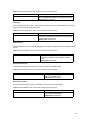
1.3.1 IC35516-T
The IC35516-T has one power LED indicator, one (optional) emergency power LED, and two LED indicators
for each of the 16 ports. See the table below for a complete LED description.
LED
Color
Description
Power
Green
Power is on.
Emergency Power
Off
Green
Power is off, or main power has failed.
Primary power has failed and optional power supply is powering the switch.
Link/Speed
Off
Green
Optional power supply is in standby mode and primary power is working.
A valid 1000 Mbps link has been established on the port.
Yellow
A valid 10/100 Mbps link has been established on the port.
Off
Green
No link has been established on the port.
A full-duplex link has been established on the port.
Blinking Green
Activity has been detected in full-duplex mode.
Yellow
A half-duplex link has been established on the port.
Blinking Yellow
Activity has been detected in half-duplex mode.
Off
No link has been established on the port.
Duplex/Activity
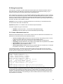
1.3.2 IC35516-G
The IntraCore 35516-G has one power LED, one (optional) emergency power LED, two LED indicators for
10/100/1000BaseT status, and one LED for GBIC status. See the table below for a complete LED
description.
6
LED
Color
Description
Power
Green
Power is on.
Off
Emergency Power Green
Power is off, or main power supply has failed.
Primary power has failed and optional power supply is powering the switch.
Off
BaseT10/100/1000 Green
Link/Speed
Yellow
Optional power supply is in standby mode and primary power is working.
A valid 1000 Mbps link has been established on the port.
Off
BaseT 10/100/1000 Green
Duplex/Activity
Blinking
No link has been established on the port.
A full-duplex link has been established on the port.
GBIC
Link
A valid 10 or 100 Mbps link has been established on the port.
Activity is detected in full-duplex mode.
Yellow
A half-duplex link has been established on the port.
Blinking Yellow
Activity is detected in half-duplex mode.
Off
Green
No link has been established on the port.
A valid 1000 Mbps link has been established on the port.
Off
No link has been established on the port.
1.4 Front and Back Panel Descriptions
Refer to the following sections for detailed descriptions of the front and back panels of the IC35516 series
switches.
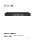
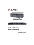
1.4.1 IC35516-T
The front panel of the IC35516-T contains the following: power and port LEDs; 12 10/100/1000BaseT ports;
4 dual-function Gigabit ports that support either 1000BaseT or GBIC-style Gigabit Ethernet ports; and a
console port.
The back panel, not shown, contains a 12 VDC jack for emergency power (optional), the primary power bay
cover plate, the primary power outlet, and the on/off switch.
7
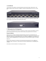
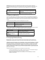
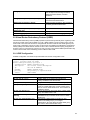
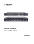
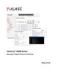
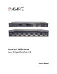
1.4.2 IC35516-G
The front panel of the IC35516-G contains the following: power and port LEDs; 12 GBIC ports; 4 dualfunction Gigabit ports that support either 1000BaseT or GBIC-style Gigabit Ethernet ports; and a console
port.
The back panel, shown below, contains a 12 VDC jack for emergency power (optional), the primary power
bay cover plate, the on/off switch, and the primary power outlet.
1.5 Management and Configuration
The switch is managed using Command Line Interface (CLI) in order to access several different command
modes. Entering a question mark (?) at each command mode’s prompt provides a list of commands.
Console Interface
Support for local, out-of-band management is delivered through a terminal or modem attached to the
EIA/TIA-232 interface. Users can access the switch by connecting a PC or terminal to the console port of the
switch, via a serial cable. The default password set on the console line is Asante (it is case-sensitive). The
default IP address is 192.168.0.1/24. The default settings for the terminal emulation program are as follows:
9600-8-N-1
Remote in-band management is available through Simple Network Management Protocol (SNMP) and
Telnet client. When connecting via a Telnet session (line vty0) the default password is also Asante (casesensitive).
See Chapter 2 for more information on connecting to the switch.
8
Chapter 2. Hardware Installation and Setup
The following guidelines will help the user to easily install the switch, and to ensure that it has the proper
power supply and environment.
2.1 Installation Overview
Follow these steps to install the IntraCore switch:
1.
2.
3.
4.
Open the box and check the contents. See Chapter 1.3 Package Contents for a complete list of the
items included with the IntraCore switch.
Install the switch in an equipment or wall rack, or prepare it for desktop placement.
Connect the power cord to the switch and to an appropriate power source.
Connect network devices to the switch.
See the sections below for more detailed installation instructions.
2.1.1 Safety Overview
The following information provides safety guidelines to ensure the user’s safety and to protect the
switch from damage.
Note: This information is intended as a guideline, and may not include every possible hazard to
which the user may be exposed. Use caution when installing this switch.
•
•
•
•
•
Only trained and qualified personnel should be allowed to install or replace this equipment
Always use caution when lifting heavy equipment
Keep the switch clean
Keep tools and components off the floor and away from foot traffic
Avoid wearing rings or chains (or other jewelry) that could get caught in the switch. Metal objects
can heat up and cause serious injury to persons and damage to the equipment. Avoid wearing
loose clothing (such as ties or loose sleeves) when working around the switch
When working with electricity, follow these guidelines:
•
•
•
•
•
Disconnect all external cables before installing or removing the cover
Do not work alone when working with electricity
Always check that the cord has been disconnected from the outlet before performing hardware
configuration
Do not tamper with the equipment. Doing so could void the warranty
Examine the work area for potential hazards (such as wet floors or ungrounded cables)
2.1.2 Recommended Installation Tools
You will need the following tools and equipment (not included) to install the switch into an equipment rack:
•
•
•
Flat head screwdriver
Phillips head screwdriver
Antistatic mat or foam
9
2.1.3 Power Requirements
The electrical outlet should be located near the switch and be easily accessible. It must also be properly
grounded.
Make sure the power source adheres to the following guidelines:
•
•
Power: Auto Switching 90-260 VAC
Frequency range: 50/60 Hz
2.1.4 Environmental Requirements
The switch must be installed in a clean, dry, dust-free area with adequate air circulation to maintain the
following environmental limits:
•
•
Operating Temperature: 0° to 40°C (32° to 104°F)
Relative Humidity: 10% to 90% non-condensing
Avoid direct sunlight, heat sources, or areas with high levels of electromagnetic interference. Failure to
observe these limits may cause damage to the switch and void the warranty.
2.1.5 Cooling and Airflow
The IC35516 switches use internal fans for air-cooling. Do not restrict airflow by covering or obstructing air
vents on the sides of the switch.
2.2 Installation into an Equipment Rack
Important! Before continuing, disconnect all cables from the switch.
To mount the switch onto an equipment rack:
1.
2.
3.
4.
5.
6.
Place the switch on a flat, stable surface.
Locate a rack-mounting bracket (supplied) and place it over the
mounting holes on one side of the switch.
Use the screws (supplied) to secure the bracket (with a Phillips
screwdriver).
Repeat the two previous steps on the other side of the switch.
Place the switch in the equipment rack.
Secure the switch by securing its mounting brackets onto the equipment rack with the appropriate
screws (supplied).
Important! Make sure the switch is supported until all the mounting screws for each bracket are secured to
the equipment rack. Failure to do so could cause the switch to fall, which may result in personal injury or
damage to the switch.
2.2.1 Equipment Rack Guidelines
Use the following guidelines to ensure that the switch will fit safely within the equipment rack:
•
•
•
Size:
IC35516-T: 17.1 x 10.1 x 1.6 inches (434 x 257 x 41 mm)
IC35516-G: 17.5 x 14.0 x 2.6 inches (445 x 356 x 66 mm)
Ventilation: Ensure that the rack is installed in a room in which the temperature remains below 40°
C (104° F). Be sure that no obstructions, such as other equipment or cables, block airflow to or
from the vents of the switch
Clearance: In addition to providing clearance for ventilation, ensure that adequate clearance for
servicing the switch from the front exists
10
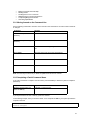
2.3 Gigabit Interface Converters
The GBIC Interface is the industry standard for Gigabit Ethernet Interfaces. Some of the benefits of GBIC
include reducing the components needed in a “spares” inventory, being able to choose from a wide variety
of manufacturers with cross-vendor compatibility, and having competitive prices.
Instructions for installing, removing, and maintaining GBIC modules are provided in following sections.
Important! The 35516-G has 12 GBIC ports that are paired— port numbers 1/2, 3/4, 5/6, 7/8, 10/12, and
14/16. DO NOT use more than one copper GBIC module per pair (maximum 8 modules).
Model
GBIC 1000SX
GBIC 1000LX
GBIC 1000T
Part Number
99-00549-01
99-00550-01
99-00673-01
Standard
1000BaseSX
1000BaseLX
1000BaseT
GBIC 1000TP
99-00647-07
1000BaseT
Media
Multi-mode fiber
Single mode fiber
Category 5 UTP (or better)
copper
Category 5 UTP (or better)
copper
Table 2-1 GBIC Modules by Asanté
2.3.1 Installing a GBIC
GBICs are hot-swappable. This means that they can be inserted and removed while the switch is powered
on. However, please allow 40-60 seconds for the switch to recognize the module when it has been installed
while the switch is on.
1.
2.
3.
4.
5.
6.
Wearing an ESD (electro-static discharge) wrist strap, remove the GBIC module from its protective
packaging.
Verify that the GBIC is the correct type for the network (see the table above).
Grip the sides of the GBIC with the thumb and forefinger, and then insert the GBIC into the slot on
the face of the switch.
Slide the GBIC into the slot until it clicks into place.
Fiber GBIC modules: Remove the rubber plugs from the end of the GBIC module. Save them for
future use.
Attach the appropriate cable.
Note: After installing a GBIC 1000T module, the link LED may light even before a valid cable has been
connected. This is a normal condition for most 1000BaseT GBIC modules.
Note: Auto-negotiation must be disabled on a port in which a copper GBIC module is installed. Copper
GBICs themselves control auto-negotiation.
11
2.3.2 Removing a GBIC
Caution: GBIC 1000T modules run hot under normal operating conditions. When it has been removed from
the system, place it on a heat-resistant surface and allow the module to cool before handling.
Note: Unnecessary removals/insertions of a GBIC module will lead to premature failure of the GBIC
connector. The rated duty cycle for a GBIC module is 100 to 500 removals/insertions.
Follow the steps below to remove a GBIC interface from a Gigabit Ethernet module:
1.
Disconnect the cable from the GBIC module.
2. Release the GBIC from the slot by simultaneously squeezing the locking tabs on both sides of the
3.
4.
GBIC.
Slide the GBIC out of the slot.
Fiber GBIC modules: Install the rubber plugs in the GBIC optical bores, and place the GBIC in
protective packaging.
2.3.3 GBIC Care and Handling
Follow these GBIC maintenance guidelines:
•
•
•
GBICs are static-sensitive. To prevent ESD damage, follow normal board and component handling
procedures. Wear an ESD wrist strap
Fiber GBIC modules are very sensitive to dust and contaminants. When they are not connected to
a fiber-optic cable, install the rubber plugs in the optical bores
The ferrules of the optical connectors may pick up debris that can obstruct the optical bore. Use an
alcohol swab or equivalent to clean the ferrules of the optical connector
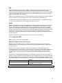
2.4 Installing the Optional Emergency Power Supply
To ensure increased reliability for mission-critical applications, the IC35516 can be equipped with a 12 VDC
emergency backup power supply (the IC35-EPS12, sold separately). When installed, the emergency power
supply is in standby mode. Should the primary unit fail, the DC backup automatically switches on and the
LED on the front panel lights. In addition, an SNMP fault notice is sent.
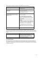
To verify the primary power status, use the Router# show system command. Under System Information,
you will see the power unit status.
System Information
-----------------System up since: 10:34:43 Fri Feb 07 2003
PROM Image Version/Date:
1.01A/Nov 20 2002 20:24:10
DRAM Size:
64.0MB
Flash Size:
8.0MB
Config NVRAM Size:
128KB
Console Baud Rate: 9600 bps
Serial No. :
Power Unit Status = OK
Should the IC35-EPS12 become active due to a fault with the primary power, the unit should be swapped
out at the earliest convenience and sent for repair. The IC35-EPS12 is designed to be a temporary
replacement when the primary power fails, not a permanent replacement.
To install the optional power supply, simply attach the 12 VDC connector of the power supply to the jack
located in the center of the rear panel of the switch. Connect the power cord to the power supply and plug
the power cord into an outlet.
Important! The optional power supply becomes HOT under normal operating conditions. To avoid damage
or injury, set the power supply on a heat-resistant surface and USE CAUTION when handling the unit.
12
2.5 Connecting Power
Important: Carefully review the power requirements (Chapter 2.1.3) before connecting power to the switch.
Use the following procedure to connect power to the switch:
1.
2.
3.
Plug one end of the supplied power cord into the power connector on the back of the switch.
Plug the other end into a grounded AC outlet.
Turn on the switch’s power. The power LED will begin its initialization process.
The front panel LEDs blink and the power LED illuminates when it has initialized. The switch is ready for
connection to the network.
Important: If the power does not come on, check the next section to ensure that the correct cabling is used.
2.6 Connecting to the Network
The switch may be connected to an Ethernet network with the switch powered on or off. Use the following
procedure to make the network connections:
1.
2.
Connect the network devices to the switch, following the cable guidelines outlined below.
After the switch is connected to the network, it can be configured for management capabilities (see
the following chapters for information on configuration).
2.6.1 10/100/1000BaseT Ports Cabling Procedures
The 10/100/1000 ports on the switch allow for the connection of 10BaseT, 100BaseTX, or 1000BaseT
network devices. The ports are compatible with IEEE 802.3 and 802.3u standards.
Important: The switch must be located within 100 meters of its attached 10BaseT or 100BaseTX devices.
Use the following guidelines to determine the cabling requirements for the network devices:
•
•
Connecting to Network Station: Category 5 UTP (Unshielded TwistedPair) straight-through cable (100 meters maximum) with RJ-45 connectors
Connecting to Repeater/Hub/Switch’s Uplink port: Category 5, UTP
straight-through cable (100 meters maximum) with RJ-45 connectors
Note: These switches have no specific uplink ports. All 10/100/1000 ports on these
switches are auto-sensing MDI/MDI-X. This advanced feature means that when the
ports are operating at 10/100Mbps, they will automatically determine whether the device at the other end of
the link is a hub, switch, or workstation, and adjust its signals accordingly. No cross-over cables are
required.
Although 10/100BaseT requires only pins 1, 2, 3, and 6, Asanté strongly recommends cables with all 8 wires
connected as shown in Table 2-2 below.
13
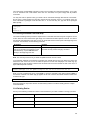
1000BaseT requires that all four pairs (8 wires) be connected correctly, using Category 5 or better
Unshielded Twisted Pair (UTP) cable (to a distance of 100 meters). Table 2-2 shows the correct pairing of all
eight wires.
Pin Number
1
2
3
4
5
6
7
8
Pair Number & Wire Colors
2 White/Orange
2 Orange/White
3 White/ Green
1 Blue/White
1 White/Blue
3 Green/White
4 White/Brown
4 Brown/White
Table 2-2 Pin Numbers and Wire Colors
2.6.2 Gigabit Ethernet Ports Cabling Procedures
Cabling requirements for the optional hardware modules depend on the type of module installed. Use the
following guidelines to determine the particular cabling requirements of the module(s):
•
•
•
•
•
•
1000BaseSX GBIC: Cables with SC-type fiber connectors; 62.5-micron multi-mode fiber (MMF)
media up to 275 meters (902 feet) long, or 50-micron MMF media up to 550 meters (1805 feet)
long
1000BaseLX GBIC: Cables with SC-type fiber connectors; 10-micron single-mode fiber media up to
5 kilometers (16,405 feet) long
1000BaseLH GBIC: Cables with SC-type fiber connectors; 10-micron single-mode fiber media up to
20 kilometers (65,617 feet) long
1000BaseLX Long Haul GBIC: Cables with SC-type fiber connectors; 10-micron single-mode fiber
media up to 100 kilometers (328,100 feet) long
1000BaseLZ GBIC: Cables with SC-type fiber connectors; 10-micron single-mode fiber media up to
120 kilometers (393,701 feet) long
1000BaseT: Category 5 or better Unshielded Twisted Pair (UTP) cable to a distance of 100 meters
(328.1 feet) long
When attaching a workstation to the switch, a standard straight-through CAT5 cable may be used, even
when the workstation is attached via a patch panel. No crossover cable is needed with the MDX/MDI ports.
It is recommended that the switch be kept off the network until proper IP settings have been set.
2.7 Setup
In order to configure the switch, connect to it through a console (out-of-band management), running a
terminal emulation program, such as HyperTerminal.
2.7.1 Connecting to a Console
To connect the switch to a console or computer, set up the system in the following manner:
1.
2.
3.
Plug power cord into the back of switch.
Attach a straight-through serial cable between the RS232 console port and a COM port on the PC.
Set up a HyperTerminal (or equivalent terminal program) in the following manner:
•
•
Open the HyperTerminal program, and from its file menu, right-click on Properties
Under the Connect To tab, choose the appropriate COM port (such as COM1 or COM2)
14
•
•
•
Under the Settings tab, choose VT100 for Emulation mode
Select Terminal keys for Function, Arrow, and Ctrl keys. Be sure the setting is for Terminal keys,
NOT Windows keys
Back under the Connect To tab, press the Configuration button
•
•
•
Set the data rate to 9600 Baud
Set data format to 8 data bits, 1 stop bit and no parity
Set flow control to NONE
Now that terminal is set up correctly, power on the switch (boot sequence will display in terminal.)
After connecting to the console, a prompt like the following will appear:
User Access Verification
Password:
By default, the initial password for access via console and telnet is Asante (case-sensitive). See the
following section for setting new passwords on the terminal lines.
15
2.8 Setting Passwords
The switch ships with a default of no enable password, which allows anyone on the network access to
various privilege levels. To prevent unauthorized changes to the switch’s configuration, you should set an
enable password for access to switch management. Follow the example below to assign a privileged
password.
Router> enable
Password: <no password by default; press Enter>
Router# configure terminal
Router(config)# enable password ?
0
Specifies an UNENCRYPTED password will follow
7
Specifies a HIDDEN password will follow
LINE The UNENCRYPTED (cleartext) 'enable' password
Router(config)# enable password 0 <password>
Router(config)# exit
Router# write [memory file]
A separate password should be set for the primary terminal line (console) and the virtual terminal lines
(telnet). The default password Asante is assigned only to the virtual terminal line Vty0. Up to three other
virtual terminal lines may be created, and they each will require a separate password.
Note: It is recommended that you change the default telnet password to prevent unauthorized access to the
switch.
Router(config)# line ?
console Primary terminal line
vty
Virtual terminal
Router(config)# line console ?
<0-0> Line number
Router(config)# line console 0
Router(config-line)# ?
end
End current mode and change to enable mode
exec-timeout Set timeout value
exit
Exit current mode and down to previous mode
help
Description of the interactive help system
no
Negate a command or set its defaults
password
Set a password
quit
Exit current mode and down to previous mode
Router(config-line)# password ?
LINE The UNENCRYPTED (cleartext) line password
0
Specifies an UNENCRYPTED line password will follow
7
Specifies a HIDDEN line password will follow
Router(config-line)# password Asante
Router(config-line)# end
Router# write ?
file
Write to configuration file
memory
Write configuration to the file (same as write file)
terminal Write to terminal
Router# write file
Writing current-config to startup-config, Please wait...
Configuration saved to startup-config file
Router#
The password can be set at unencrypted (level 0) or hidden, or encrypted (level 7).
Router(config-line)# password ?
LINE The UNENCRYPTED (cleartext) line password
0
Specifies an UNENCRYPTED line password will follow
7
Specifies a HIDDEN line password will follow
16
2.9 Configuring an IP Address
The switch ships with the default IP address 192.168.0.1/24. Connect via the serial port in order to assign
the switch an IP address on your network.
The physical ports (or switchports) of the IC35516 are L2 ports, and cannot have an IP address assigned to
them. By default, each switchport belongs to VLAN 1, a virtual interface (veth1) that may be assigned a
primary, as well as any number of secondary, IP addresses. Use the following instructions to configure an IP
address to the switch. The network administrator may later assign primary IP addresses to any other VLAN
created.
Follow the steps below to change the switch’s IP address.
1.
2.
3.
4.
5.
6.
Connect to the console and press Enter at the Password prompt, as described above.
The screen will display the user mode prompt, Router>.
Type enable. The new prompt is Router#.
Type configure terminal. The new prompt is Router(config)#.
The default IP address is assigned to the veth1 interface. Type interface veth1. The new prompt is
Router(config-if-veth1)#.
Type ip address and the new address. Your screen will look like this example:
Router> enable
Router# configure terminal
Router(config)# interface veth1
Router(config-if-veth1)# ip address 192.168.123.254 255.255.255.0
Router(config-if-veth1)# end
Router# show interface veth1
Veth1 is up, line protocol is up
Hardware is virtual interface VLAN 1, address is 00:00:94:D2:56:FA
Encapsulation ARPA, Flags: <UP,BROADCAST,RUNNING,MULTICAST>
inet 192.168.123.254/24 broadcast 192.168.123.255
ARP Type: ARPA, ARP Timeout: 14400 seconds
Router# write file
Writing current-config to startup-config. Please wait.
Configuration saved to startup-config file
Router#
It is also acceptable to enter the subnet mask by typing ip address 192.168.123.254/24. Use the
show interface veth1 command from privileged mode to see the new IP address. The new IP address
automatically writes over the default IP address.
See Chapter 5 for more information on assigning IP addresses to interfaces.
2.9.1 Setting a Default IP Gateway Address
To define the default IP gateway for the switch, insert a static route:
Router(config)# ip route 0.0.0.0 255.255.255.255 <gateway IP> <mask>
17
2.10 Restoring Factory Defaults
If you ever need to restore the switch to its factory default settings, follow the commands shown in the
following screen.
Router> enable
Router# reload ?
factory-default Reset ALL system parameters to factory default
<cr>
Router# reload factory-default
The switch is now ready for configuration. Refer to the following chapters for management and configuration
information.
2.11 System Boot Parameters
The IC35516 has two boot banks to store its runtime code. You can select which bank will be used for the
next boot with the following command:
Router(config)# boot system flash {bank1|bank2}
18
Chapter 3. Understanding the Command Line Interface (CLI)
The switch utilizes Command Line Interface (CLI) to provide access to several different command modes.
Each command mode provides a group of related commands.
After logging into the system, the user is automatically in the user top (user EXEC) mode. From the user top
mode you can enter into the privileged top (privileged EXEC) mode. From the privileged EXEC level, you
can access the global configuration mode and specific configuration modes: interface, router, and route-map
configuration. Entering a question mark (?) at the system prompt allows you to obtain a list of commands
available for each command mode. Almost every router configuration command also has a no form. You
can use the no form to disable a feature or function. For example, ARP is enabled by default. Specify the
command no arp to disable the ARP table (see section 3.7).
Document Conventions
Command descriptions use the following conventions:
•
•
•
•
•
•
Vertical bars ( | ) separate alternative, mutually exclusive, elements
Square brackets ([ ]) indicate optional elements
Braces ({ }) indicate a required choice
Braces within square brackets ([{ }]) indicate a required choice within an optional element
Boldface indicates commands and keywords that are entered literally as shown
Italics indicate arguments for which you supply values
Access Each Command Mode
The following sections describe how to access each of the CLI command modes:
•
User Top Mode: Router>
•
Privileged Top Mode: Router#
•
Global Configuration Mode: Router(config)#
•
Interface Configuration Mode: Router(config-if-IFNAME)#
•
Router Configuration Mode: Router(config-RTNAME-router)#
•
Route-Map Configuration Mode: Router(config-route-map)#
3.1 User Top (User EXEC) Mode
After you log in to the router, you are automatically in user top (user EXEC) command mode. The user-level
prompt consists of the host name followed by the angle bracket (>):
Router>
The default host name is Router unless it has been changed during initial configuration, using the setup
command.
The user top commands available at the user level are a subset of those available at the privileged level. In
general, the user top commands allow you to connect to remote devices, change terminal settings on a
temporary basis, perform basic tests, and show system information.
To list the commands available in user top mode, enter a question mark (?). Use a space and a question
mark (?) after entering a command to see all the options for that particular command.
Command
?
show ?
Purpose
Lists the user EXEC commands.
Lists all the options available for the given
command.
19
User top commands:
Router> ?
enable
exit
help
ping
quit
show
tracert
cls
Router>
Turn on privileged mode command
Exit current mode and down to previous mode
Description of the interactive help system
Send echo messages
Exit current mode and down to previous mode
Show running system information
Trace route to destination
Clear screen
You may also enter a question mark after a letter or string of letters to view all the commands that start with
that letter (with no space between the letter and the question mark). See section 3.8.2.
3.2 Privileged Top (Privileged EXEC) Mode
Because many of the privileged commands set the system configuration parameters, privileged access can
be password protected to prevent unauthorized use. The privileged command set includes those commands
contained in user EXEC mode, as well as the configure command through which you can access the
remaining command modes. Privileged EXEC mode also includes high-level testing commands, such as
debug.
The following example shows how to access privileged EXEC mode. Note that the prompt changes from
Router> to Router#:
Router> enable
Password:
Router#
Command
Purpose
Router> enable [password]
Enters the privileged EXEC mode.
Router# ?
Lists privileged EXEC commands.
If the user has set a password, the system prompts for it before allowing access to privileged EXEC mode. If
an enable password has not been set, the enable mode can be accessed only through the console. The
user can enter the enable password global configuration command to set the password that restricts
access to privileged mode.
To return to user EXEC mode, use the following command:
Command
Purpose
Router# disable
Returns you to user EXEC mode from privileged
EXEC mode.
In general, the top (privileged) commands allow you to change terminal settings on a temporary basis,
perform basic tests, and list system information. To list the commands available in top mode, enter a
question mark (?) at the prompt, as shown in the following example. Enter a question mark (?) after a
command to see all the options for that command.
20
Router> enable
Router# ?
clear
Reset functions
clock
Manage the system clock
configure Enter configuration mode
copy
Copy from one file to another
debug
Debugging functions
disable
Turn off privileged mode command
erase
Erase a filesystem
exit
Exit current mode and down to previous mode
help
Description of the interactive help system
no
Negate a command or set its defaults
ping
Send echo messages
quit
Exit current mode and down to previous mode
reload
Halt and perform a cold restart
show
Show running system information
tracert
Trace route to destination
write
Write running configuration to memory, network, or terminal
cls
Clear screen
Router#
Important! You MUST save any changes you make in running configuration to the startup configuration file
if you want those changes to remain after a system reload. From the privileged level, configurations can be
saved using the write command, or by using the copy running-config startup-config command.
From the privileged level, you can access global configuration mode, as described in the following section.
3.3 Global Configuration Mode
Global configuration commands apply to features that affect the system as a whole, rather than just one
protocol or interface. Commands to enable a particular routing function are also global configuration
commands. To enter the global configuration mode, use the configure terminal command.
The following example shows how to access and exit global configuration mode and list global configuration
commands.
Command
Purpose
Router# configure terminal
From privileged EXEC mode, enters global
configuration mode.
Lists the global configuration commands.
Router(config)# ?
To exit global configuration command mode and return to privileged EXEC mode, use one of the following
commands:
Command
Purpose
exit
end
Ctrl-Z
Exits global configuration mode and returns to
privileged EXEC mode.
To list the commands available in global configuration mode, enter a question mark (?) at the prompt, as
shown in the following example. Enter a question mark (?) after a command to see all the options for that
command.
21
Router# configure terminal
Router(config)# ?
access-list
Add an access list entry
arp
Set static arp entry
boot
Modify system boot parameters
duplicate-ip
Duplicate IP Address detection Global Commands
enable
Modify enable password parameters
end
End current mode and change to enable mode
exit
Exit current mode and down to previous mode
help
Description of the interactive help system
hostname
Set system's network name
interface
Select an interface to configure
ip
Global IP configuration subcommands
line
Configure a terminal line
logging
Message Logging global configuration commands
mac-address-table MAC Address Table global configuration command
no
Negate a command or set its defaults
quit
Exit current mode and down to previous mode
route-map
Create route-map or enter route-map command mode
router
Enable a routing process
service
Set up miscellaneous service
snmp-server
Modify SNMP parameters
spanning-tree
Enable Spanning Tree Protocol
vlan
VLAN global configuration command
Router(config)#
From global configuration mode, you can access three additional configuration modes: The interface,
router, and route-map commands are used to access their respective configuration modes.
3.3.1 Interface Configuration Mode
Many features are enabled on a per-interface basis. Interface configuration commands modify the operation
of an interface such as an Ethernet or serial port. Interface configuration commands always follow an
interface global configuration command, which defines the interface type (Ethernet or Virtual interfaces. The
virtual interfaces are bound to VLANs and can be assigned IP addresses).
In the following example, Ethernet interface eth1 is about to be configured. The new prompt,
Router(config-if-eth1)#, indicates the interface configuration mode. In this example, the user asks
for help by requesting a list of commands.
Router(config)# interface eth1
Router(config-if-eth1)# ?
description
Interface specific description
end
End current mode and change to enable mode
exit
Exit current mode and down to previous mode
help
Description of the interactive help system
ip
Interface Internet Protocol config commands
mtu
Set the interface Maximum Transmission Unit (MTU)
no
Negate a command or set its defaults
quit
Exit current mode and down to previous mode
shutdown
Shutdown the selected interface
spanning-tree
Spanning Tree Protocol interface command
switchport
Port operating in L2 mode
Router(config-if-eth1)#
To exit interface configuration mode and return to global configuration mode, enter the exit command. To
exit configuration mode and return to top mode, use the end command or press Ctrl-Z.
22
3.3.2 Router Configuration Mode
Router configuration commands are used to configure an IP routing protocol and always follow a router
command. To list the available router configuration keywords, enter the router command followed by a
space and a question mark (?) at the global configuration prompt.
Router(config)# router ?
ospf
Open Shortest Path First
rip
Routing Information Protocol (RIP)
Router(config)# router
In the following example, the router is configured to support the Routing Information Protocol (RIP). The new
prompt is Router(config-rip-router)#.
Router(config)# router rip
Router(config-rip-router)# ?
default-information Control distribution of default route
default-metric
Set a metric of redistribute routes
distance
Administrative distance
distribute-list
Filter networks in routing updates
end
End current mode and change to enable mode
exit
Exit current mode and down to previous mode
help
Description of the interactive help system
neighbor
Specify a neighbor router
network
Enable routing on an IP network
no
Negate a command or set its defaults
offset-list
Modify RIP metric
passive-interface
Suppress routing updates on an interface
quit
Exit current mode and down to previous mode
redistribute
Redistribute information from another routing protocol
timers
Adjust routing timers
version
Set routing protocol version
Router(config-rip-router)#
To exit router configuration mode and return to global configuration mode, enter the exit command. To exit
configuration mode and return to privileged EXEC mode, use the end command or press Ctrl-Z.
3.3.3 Route-Map Configuration Mode
Use the route-map configuration mode to configure the routing table and the source and destination
information. To access and list the route-map configuration commands, enter route-map command at the
global configuration mode.
In the following example, a route map named mymap is configured. The new prompt is Router(config-routemap)#. Enter a question mark (?) to list route-map configuration commands.
Router(config)# route-map mymap permit 30
Router(config-route-map)# ?
end
End current mode and change to enable mode
exit
Exit current mode and down to previous mode
help
Description of the interactive help system
match
Match values from routing table
no
Negate a command or set its defaults
on-match
Exit policy on matches
quit
Exit current mode and down to previous mode
route-map Create route-map or enter route-map command mode
set
Set values in destination routing protocol
Router(config-route-map)#
To exit route-map configuration mode and return to global configuration mode, enter the exit command. To
exit configuration mode and return to privileged EXEC mode, use the end command or press Ctrl-Z.
23
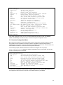
3.4 Advanced Features Supported within the Command Mode
Entering a question mark (?) at the system prompt displays a list of commands available for each command
mode. You can also get a list of any command's associated keywords and arguments with the contextsensitive help feature.
To get help specific to a command mode, a command, a keyword, or an argument, perform one of the
following commands:
Command
Purpose
help
Obtain a brief description of the help system in any
command mode.
List all commands available for a particular
command mode.
?
When using context-sensitive help, the space (or lack of a space) before the question mark (?) is significant.
To obtain a list of commands that begin with a particular character sequence, type in those characters
followed immediately by the question mark (?). Do not include a space. This form of help is called word help,
because it completes a word for you.
To list keywords or arguments, enter a question mark (?) in place of a keyword or argument. Include a space
before the question mark (?). This form of help is called command syntax help, because it reminds you
which keywords or arguments are applicable based on the command, keywords, and arguments you already
have entered.
You can abbreviate commands and keywords to the number of characters that allow a unique abbreviation.
For example, you can abbreviate the configure terminal command to config term, or even con t. Because
the shortened form of the command is unique, the router will accept the shorted form and execute the
command.
Enter the help command (which is available in any command mode) for a brief description of the help
system:
Router# help
CLI/VTY provides advanced help feature. When you need help,
anytime at the command line please press '?'.
If nothing matches, the help list will be empty and you must backup until
entering a '?' shows the available options.
Two styles of help are provided:
1. Full help is available when you are ready to enter a command argument (e.g.
'show ?') and describes each possible argument.
2. Partial help is provided when an abbreviated argument is entered and you
want to know what arguments match the input (e.g. 'show cl?'.)
Router# show cl?
clock Display the system clock
Router# show cl
As described in the help command output, you can enter a partial command name and a question mark (?)
to obtain a list of commands beginning with a particular character set.
24
Example of Context Sensitive Help
The following example illustrates how the context-sensitive help feature creates an access list from the
configuration mode.
Enter the letters “co” at the system prompt followed by a question mark (?). Do not leave a space between
the last letter and the question mark (?). The system provides the commands that begin with co.
Router# co?
configure
copy
Router# co
Enter configuration mode
Copy from one file to another
Enter the configure command followed by a space and a question mark (?) to list the command's keyword(s)
and a brief explanation:
Router# configure ?
terminal Configure from the terminal
Note that in the example below, if you enter the configure command followed by the Carriage Return (Enter
or Return key), you will be prompted that the command is incomplete.
Router# configure
% Command incomplete.
Router#
Generally, uppercase letters represent variables. For example, after entering a command, such as
hostname, and using a space and a question mark, you will be prompted for the new name, represented by
WORD. In cases where an IP address is the variable, the uppercase letters A.B.C.D will represent it.
Router(config)# hostname ?
WORD This system's network name
In this access list example below, there are two further options listed after the question mark. The user may
enter a source wildcard, or the command is complete as it is already entered. The carriage return symbol
(<cr>) indicates a carriage return is needed to enter the command. More information on access lists is found
in Chapter 5.
Router(config)# access-list 99 deny 192.168.123.0 ?
A.B.C.D Source wildcard. e.g. 0.0.0.255
<cr>
Router(config)# access-list 99 deny 192.168.123.0
3.5 Checking Command Syntax
The CLI user interface provides an error indicator, a caret symbol (^). The caret symbol appears at the point
in the command string where you have entered an incorrect letter, command, keyword, or argument.
In the following example, suppose you want to enable rip router:
Router(config)# routed rip
^
% Invalid input detected at '^' marker.
There is no command starting with routed, so the first invalid input is ‘d’. Hence, the indicated caret symbol
(^)marks the invalid input.
Router(config)# route
% Ambiguous command.
Router(config)#
25
In the example above, a command has been issued that is unknown or ambiguous.
Router(config)# router
% Command incomplete.
Router(config)#
In the example above a command has been issued that is incomplete. In the following examples, various
correct commands (using route) are displayed.
Router(config)# route?
route-map
Create route-map or enter route-map command mode
router
Enable a routing process
Router(config)# route
Router(config)# router ?
ospf
Open Shortest Path First
rip
Routing Information Protocol (RIP)
Router(config)# router
Router(config)#router rip
Router(config-rip-router)#
3.6 Using CLI Command History
The CLI user interface provides a history or record of commands that you have entered. This feature is
particularly useful for recalling long or complex commands or entries, including access lists. To recall
commands from the history buffer, use one of the following commands:
Command
Purpose
Press Ctrl-P or the up arrow
key
Recall commands in the history buffer, beginning with
the most recent command. Repeat the key sequence
to recall successively older commands.
Press Ctrl-N or the down arrow
key
Return to more recent commands in the history buffer
after recalling commands with Ctrl-P or the up arrow
key. Repeat the key sequence to recall successively
more recent commands.
While in EXEC mode, list the last several commands
entered.
show history
3.7 Using the No and Default Forms of Commands
Almost every router configuration command has an opposite no form that negates or reverses a command.
In general, the no form is used to disable a function that has been enabled. To re-enable a disabled
function, or to enable a function that is disabled by default, use the command without the no keyword. For
example, Address Resolution Protocol (ARP) is enabled by default. Specify the command no arp to disable
the ARP table; to re-enable the ARP table, use the arp command.
3.8 Using Command-Line Editing Features and Shortcuts
There are a variety of shortcuts and editing features enabled for the CLI command-line interface. The
following subsections describe these features:
•
•
Moving Around on the Command Line
Completing a Partial Command Name
26
•
•
•
•
•
•
Editing Command Lines that Wrap
Deleting Entries
Scrolling Down a Line or a Screen
Redisplaying the Current Command Line
Transposing Mistyped Characters
Controlling Capitalization
3.8.1 Moving Around on the Command Line
Use the following commands to move the cursor around on the command line in order to make corrections
or changes:
Command
Purpose
Press Ctrl-B or press the left
arrow key.
Move the cursor back one character.
Press Ctrl-F or press the right
arrow key.
Move the cursor forward one character.
Press Ctrl-A.
Move the cursor to the beginning of the command
line.
Press Ctrl-E.
Move the cursor to the end of the command line.
Press Esc B.
Move the cursor back one word.
Press Esc F.
Move the cursor forward one word.
Note: The arrow keys function only on ANSI-compatible terminals such as VT100s.
3.8.2 Completing a Partial Command Name
If you cannot remember a complete command name, press the Tab key to allow the system to complete a
partial entry.
Keystrokes
Purpose
Enter the first few letters and
press the Tab key.
Complete a command name.
If your keyboard does not have a Tab key, press Ctrl-I instead.
In the following example, when you enter the letters “conf” and press the Tab key, the system provides the
complete command:
Router# conf<Tab>
Router# configure
27
The command is not immediately executed, so that you may modify the command if necessary. If you enter
a set of characters that could indicate more than one command, the system simply lists all possible
commands.
You may also enter a question mark (?) to obtain a list of commands that begin with that set of characters.
Do not leave a space between the last letter entered and the question mark (?). For example, there are
three commands in privileged mode that start with co. To see what they are, type co? at the privileged
EXEC prompt:
Router# co?
configure
copy
Router# co
3.8.3 Editing Command Lines that Wrap
The enhanced editing feature provides a wraparound for commands that extend beyond a single line on the
screen. When the cursor reaches the right margin, the command line shifts 8 spaces to the left. You cannot
see the first eight characters of the line, but you can scroll back and check the syntax at the beginning of the
command. To scroll back, use the following command:
Keystrokes
Purpose
Press Ctrl-B or the left arrow key repeatedly
until you scroll back to the beginning of the
command entry, or press Ctrl-A to return
directly to the beginning of the line.
Return to the beginning of a command line to verify that
you have correctly entered a lengthy command.
Note: The arrow keys function only on ANSI-compatible terminals such as VT100.
In the following example, the access-list command entry extends beyond one line. When the cursor first
reaches the end of the line, the line is shifted 8 spaces to the left and redisplayed. The dollar sign ($)
indicates that the line has been scrolled to the left. Each time the cursor reaches the end of the line, it is
again shifted 8 spaces to the left.
Router(config)# access-list 101 permit icmp 192.168.123.0 0.0.0.255 192
Router(config)# $ st 101 permit icmp 192.168.123.0 0.0.0.255 192.168.0.1
When you have completed the entry, press Ctrl-A to check the complete syntax before pressing Enter to
execute the command. The dollar sign ($) appears at the end of the line to indicate that the line has been
scrolled to the right:
Router(config)# access-list 101 permit icmp 192.168.123.0 0.0.0.255 192$
Use line wrapping in conjunction with the command history feature to recall and modify previous complex
command entries.
3.8.4 Deleting Entries
Use any of the following commands to delete command entries if you make a mistake or change your mind:
Keystrokes
Purpose
Press the Delete or Backspace
key.
Erase the character to the left of the cursor.
Press Ctrl-D.
Delete the character at the cursor.
Press Ctrl-K.
Delete all characters from the cursor to the end of the command line.
28
Press Ctrl-U or Ctrl-X.
Delete all characters from the cursor to the beginning of the command
line.
Press Ctrl-W.
Delete the word to the left of the cursor.
Press Esc D.
Delete from the cursor to the end of the word.
3.8.5 Scrolling Down a Line or a Screen
When using a command that list more information than will fill on the screen, the prompt --More-- is
displayed at the bottom of the screen. Whenever the More prompt is displayed, use the following keystrokes
to view the next line or screen:
Keystrokes
Purpose
Press the Return key.
Scroll down one line.
Press the Spacebar.
Scroll down one screen.
3.8.6 Redisplaying the Current Command Line
If you are entering a command and the system suddenly sends a message to your screen, you can easily
recall your current command line entry. To do so, use the following command:
Keystrokes
Purpose
Press Ctrl-L or Ctrl-R.
Redisplay the current command line.
3.8.7 Transposing Mistyped Characters
If you have mistyped a command entry, you can transpose the mistyped characters by using the following
command:
Keystrokes
Purpose
Press Ctrl-T.
Transpose the character to the left of the cursor with the character
located at the cursor.
3.8.8 Controlling Capitalization
You can toggle between uppercase and lowercase letters with simple keystroke sequences. To do so, use
the following command:
Keystrokes
Purpose
Press Esc C.
Capitalize at the cursor. Press Esc C or Alt-C again to return to
lowercase letters.
29
3.9 Passwords and Privileges Commands
The following sections describe the password and privileges commands used to control access to different
levels of the router:
•
•
•
enable password
password
service password-encryption
3.9.1 Enable Password
To set a local password to control access to various privilege levels, use the enable password command in
global configuration mode. Use the no form of this command to remove the password requirement.
Router(config)# enable password ?
0
Specifies an UNENCRYPTED password will follow
7
Specifies a HIDDEN password will follow
LINE The UNENCRYPTED (cleartext) 'enable' password
Router(config)# enable password 0 <password>
Router(config)# exit
Router# write [memory file]
3.9.2 Password
To specify a password on a line, use the password command in line configuration mode. Use the no form
of this command to remove the password.
Router(config)# line ?
console Primary terminal line
vty
Virtual terminal
Router(config)# line console ?
<0-0> Line number
Router(config)# line console 0
Router(config-line)# ?
end
End current mode and change to enable mode
exec-timeout Set timeout value
exit
Exit current mode and down to previous mode
help
Description of the interactive help system
no
Negate a command or set its defaults
password
Set a password
quit
Exit current mode and down to previous mode
Router(config-line)# password ?
LINE The UNENCRYPTED (cleartext) line password
0
Specifies an UNENCRYPTED line password will follow
7
Specifies a HIDDEN line password will follow
Router(config-line)# password Asante
Router(config-line)# end
Router# write ?
file
Write to configuration file
memory
Write configuration to the file (same as write file)
terminal Write to terminal
Router# write file
Writing current-config to startup-config, Please wait...
Configuration saved to startup-config file
Router#
30
3.9.3 Service Password-Encryption
To encrypt passwords, use the service password-encryption command in global configuration mode. Use
the no form of this command to restore the default.
Router(config)# service password-encryption
Router(config)# no service password-encryption
31
Chapter 4. Managing the System and Configuration Files
This chapter explains how to manage the system information, as well as how to manage the configuration
files for the IC35516.
4.1 Managing the System
This section discusses the following tasks needed to manage the system information of the IC35516:
•
•
•
•
•
•
•
Setting the System Clock
Configuring the Host name
Changing the Password
Testing Connections with Ping Commands
Tracing Packet Routes
Enabling Syslog
Displaying the Operating Configuration
4.1.1 Setting the System Clock
The IC35516 has a battery-backed system clock that will remain accurate even after a system restart.
To manually set the system clock, complete the following commands in privileged mode. Use a space and a
question mark (?) to display the clock set options. Restart the system after configuring the clock by typing
reload at the Router# prompt and pressing Enter.
Router# clock ?
set Set the time and date
Router# clock set ?
HH:MM:SS Current Time
Router# clock set 09:29:30 ?
<1-31> Day of the month
Router# clock set 09:29:30 28?
<1-31> Day of the month
Router# clock set 09:29:30 28 ?
MONTH Month of the year (for example: June or July)
Router# clock set 09:29:30 28 January ?
<1970-2069> Year
Router# clock set 09:29:30 28 January 2003
Router# reload <cr>
4.1.2 Specify the Hostname
The factory-assigned default host name is Router. To specify or modify the host name for the network, use
the hostname global configuration command.
Command
hostname name
Purpose
New host name for the network.
4.1.3 Changing the Password
The switch ships with a default of no password, which allows immediate access to ANYONE on the network.
In order to guard against unauthorized access, only the administrator should be allowed to change the
password. A new password is prompted for twice to avoid any typing mistakes. The new password must
have more than five characters, and less than eight characters. The password is case sensitive.
To change the password, use the following command in global configuration mode.
Command
enable password
Purpose
Change the password.
32
4.1.4 Trace Packet Routes
To discover the routes that packets will actually take when traveling to their destinations, use the following
command in top mode.
Command
tracert address
Purposes
Trace packet routes through the network.
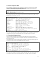
4.1.5 Test Connections with Ping Tests
The switch supports IP ping, which can be used to test connectivity to remote hosts, via their IP addresses.
Ping sends an echo request packet to an address and “listens” for a reply. The ping request will receive one
of the following responses:
•
•
Normal response—The normal response occurs in 1 to 10 seconds, depending on network traffic
Request timed out—There is no response, indicating a connection failure to the host, or the host
has discarded the ping request
Beginning in privileged EXEC mode, use this command to ping another device on the network
from the switch:
Command
ping address
Purposes
Send an ICMP echo message to a designated host for testing
connectivity.
4.1.6 Enable the System Log
The IC35516 can send syslog messages to manager servers. Syslog messages are collected by a standard
UNIX or NT type syslog daemon.
Syslog enables the administrator to centrally log and analyze configuration events and system error
messages such as interface status, security alerts, environmental conditions, and CPU process overloads.
To log messages, use the following command in global configuration mode.
Command
logging address
logging facility
logging trap
Purpose
IP address of the host to be used as a syslog server.
Facility parameters for syslog messages.
Set syslog server logging level.
4.1.7 Displaying the Operating Configuration
The configuration file may be displayed from the EXEC (enable) mode.
To see the current operating configuration, enter the following command at the enable prompt:
Router# show running-config
To see the configuration in NVRAM, enter the following command:
Router# show startup-config
If you made changes to the configuration, but did not yet write the changes to NVRAM, the results of the
show running-config will differ from the results of the show startup-config command.
33
4.2 Managing Configuration Files
This section discusses how to download configuration files from remote servers, and store configuration files
on the router at system startup.
Configuration files contain the commands the router uses to customize the function of the IC35516. The
setup command facility helps you create a basic configuration file. However, you can manually change the
configuration by typing commands in a configuration mode.
Startup configuration files are used during system startup to configure the software. Running configuration
files contain the current configuration of the software. The two configuration files can be different. For
example, you may want to change the configuration for a short period rather than permanently. In this case,
you would change the running configuration using the configure terminal command, but not save the
configuration using the copy running-config startup-config command. To change the startup
configuration, you can either save the running configuration file to the startup configuration using the copy
running-config startup-config command, or copy commands from a file server to the startup configuration
(copy tftp startup config command) without affecting the running configuration.
4.2.1 Configuring from the Terminal
The configuration files are stored in the following places:
•
•
The running configuration is stored in RAM
The startup configuration is stored in nonvolatile random-access memory (NVRAM)
To enter the configuration mode, enter the configure terminal command at the privileged EXEC prompt.
The software accepts one configuration command per line. You can enter as many configuration commands
as you want.
You can add comments to a configuration file describing the commands you have entered. Precede a
comment with an exclamation point (!).
Use the following commands to configure the software from the terminal.
Command
Purpose
configure terminal
Enters global configuration mode and select the
terminal option.
Router(config)#
The global configuration prompt. Enter the
necessary configuration commands.
End or press Ctrl-Z (^Z)
Exits global configuration mode.
Copy running-config startupconfig
Saves the configuration file to your startup
configuration. On most platforms, this step saves the
configuration to NVRAM.
In the following example, the hostname command is used to change the hostname from "Router" to
"new_name". By pressing Ctrl-Z (^Z) or entering the end command, the user quits the global configuration
mode. Finally, the copy running-config startup-config command saves the current configuration to the
startup configuration.
Router# configure terminal
Router(config)# hostname new_name
new_name(config)# end
new_name# copy running-config startup-config
When the startup configuration is in NVRAM, it stores the current configuration information in text format as
configuration commands, recording only non-default settings. The memory is checksummed to guard
against corrupted data.
34
4.2.2 Copying Configuration Files to a Network Server
You can copy configuration files from the router to a file server using TFTP. You might wish to back up a
current configuration file to a server before changing its contents, thereby allowing you to later restore the
original configuration file from the server.
Important! TFTP is not a secure protocol. Your server IP address and configuration file name will not be
protected over the public Internet. Use TFTP only on a trusted LAN connection.
To specify that the running or startup configuration file be stored on a TFTP network server, use the
following commands in the EXEC mode (Note: Copying the startup configuration file to the current running
configuration merges the two files. It is recommended that you keep a copy of the start-up configuration file
before merging the two in case you want to revert back to the original startup configuration):
Router# copy startup-config ?
running-config
Update (merge with) current system configuration
tftp:[//A.B.C.D/filename] Copy to tftp: file system
OR
Router# copy running-config ?
startup-config
Copy to startup configuration
tftp:[//A.B.C.D/filename] Copy to tftp: file system
Router# copy running-config tftp
Enter TFTP Server IP Address [A.B.C.D]?
Enter file name 'my-config' to copy?
Reply to any prompts for additional information or confirmation. The prompts will depend on how much
information has been provided in the copy command and the current setting of the file prompt command.
The command can also look like this example:
Router# copy running-config tftp://192.168.0.1/my-config
Upload file ‘my-config’ to 192.168.0.1 from running-config? [y/n] y
Accessing tftp://192.168.0.1/my-config...
[OK] 487 bytes copied in time <1 sec
4.2.3 Copying Configuration Files from a Network Server to the IC35516
You can copy configuration files from a TFTP server to the running configuration or startup configuration of
the router. You may want to do this for one of the following reasons:
1.
2.
3.
To restore a previously backed up configuration file.
To use the same configuration file for another router. For example, you may add another router to
your network and want it to have a similar configuration to the original router. By copying the file to
the new router, you can change the relevant parts rather than re-creating the whole file.
To load the same configuration commands onto all the routers in your network so that they all have
the same configurations.
The copy tftp running-config command loads the configuration files into the router as if you were typing
the commands in at the command line. The router does not erase the existing running configuration before
adding the commands unless a command in the copied configuration file replaces a command in the existing
configuration file. For example, if the copied configuration file contains a different IP address in a particular
command than the existing configuration, the IP address in the copied configuration will be used. However,
some commands in the existing configuration may not be replaced or negated. In this case, the resulting
configuration file will be a mixture of the existing configuration file and the copied configuration file, with the
copied configuration file having precedence.
35
In order to restore a configuration file to an exact copy of a file stored on a server, you need to copy the
configuration file directly to the startup configuration (using the copy tftp startup-config command) and
reload the router.
To copy a configuration file from a TFTP server to the router, use the following commands in EXEC mode:
Command
Purpose
copy tftp[[[//location]/directory]/filename]
running-config
or
copy tftp[[[//location]/directory]/filename]
startup-config
Copy a file from a TFTP server to the router.
Reply to any router prompts for additional information or confirmation. Additional prompts will depend on
how much information is provided in the copy command and the current setting of the file prompt command.
In the following example, the software is configured from the file my-config at IP address 192.168.123.59:
Router# copy tftp://192.168.123.59/my-confg running-config
Download file ‘my-config’ from 192.168.123.59 to running-config? [y/n] y
Accessing tftp://192.168.123.59/my-config...
[OK] 487 bytes copied in time <1 sec
Updating running-config...
To clear the saved configuration, use the following command from privileged mode:
Router# erase startup-config
4.3 Configuring SNMP and Spanning Tree
This section discusses the following tasks needed to configure Simple Network Management Protocol
(SNMP) and Spanning Tree Protocol (STP).
4.3.1 Configuring SNMP Support
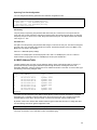
The Simple Network Management Protocol (SNMP) system consists of three parts: an SNMP manager, an
SNMP agent, and a Management Information Base (MIB). SNMP is an application-layer protocol that allows
SNMP manager and agent stations to communicate. SNMP provides a message format for sending
information between an SNMP manager and an SNMP agent. The agent and MIB reside on the router. In
configuring SNMP on the router, the relationship between the manager and the agent must be defined.
The SNMP agent gathers data from the MIB, which holds the information about device parameters and
network data. The agent also responds to the manager’s requests to get or set data. An agent can also
send unsolicited traps to the manager. Traps are messages alerting the SNMP manager to a specific event
on the network. Such events include improper user authentication, restarts, link status (up or down), closing
of a TCP connection, or loss of connection to a neighboring router. An SNMP manager can request a value
from an agent, or store or change a value in that agent.
To configure support for SNMP on the router, perform the following tasks:
•
•
•
•
Create or Modify Access Control for SNMP Community
Establish the Contact and Location of SNMP Agent
Define SNMP Trap Operations
Disable the SNMP Agent
36
Create or Modify Access Control for SNMP Community
You can configure a community string, which acts like a password, to permit access to the agent on the
router.
Read Only (ro): The string that defines access rights for reading SNMP data objects. The default is public.
Read-Write (rw): The string that defines access rights for writing SNMP data objects. The default is private.
Important! Be sure to change the SNMP default community strings in order to prevent unauthorized access
to management information.
To set up the community access string to permit access to the SNMP, use the following command from the
global command mode.
Command
snmp-server community string
{ro | rw}
Purpose
Define the community access string.
Establish the Contact, and Location of the SNMP Agent
Set the system contact and the location of the SNMP agent so that these descriptions can be accessed
through the configuration file.
To set the system contact (sysContact) string, use the following command in global configuration command.
Command
snmp-server contact text
snmp-server location text
Purpose
Set the system contact string.
Set the system location string.
Define SNMP Trap Operations
A trap is an unsolicited message sent by an SNMP agent to an SNMP manager indicating that some event
has occurred. The SNMP trap operations allow the user to configure the router to send information to a
network management application when a particular event occurs.
To define traps for the agent to send to the manager, use the following commands in global configuration
mode.
Command
snmp-server host address
Purpose
Specify the recipient of the trap message.
The 35516 can send an SNMP trap to its configured trap receivers if it detects a duplicate IP address. To
turn on duplicate IP detection, use the following command in global configuration mode:
Router(config)# duplicate-ip detect
Disable the SNMP Protocol
To disable SNMP, use the following command in global configuration mode:
Command
no snmp-server
Purpose
Disable SNMP operation.
4.3.2 Configuring Spanning Tree Protocol (STP)
The Spanning Tree Protocol (STP) is part of the IEEE 802.1D standard. It provides for a redundant network
without the redundant traffic through closed paths. For example, in a network without spanning tree protocol,
the same message will be broadcast through multiple paths, which may start an unending packet-passing
cycle. This in turn causes a great amount of extra network traffic, leading to network downtime. The STP
reduces a network like this, with multiple, redundant connections, to one in which all points are connected,
37
but where there is only one path between any two points (the connections span the entire network, and the
paths are branched, like a tree).
All of the bridges (a switch is a complex bridge) on the network communicate with each other using special
packets of data called Bridge Protocol Data Units (BPDUs). The information exchanged in the BPDUs allows
the bridges on the network to do the following:
•
•
•
•
•
Elect a single bridge to be the root bridge
Calculate the shortest path from each bridge to the root bridge
Select a designated bridge on each segment, which lies closest to the root and forwards all traffic
to it
Select a port on each bridge to forward traffic to the root
Select the ports on each bridge that forward traffic, and place the redundant ports in blocking states
Spanning Tree Parameters
The operation of the spanning tree algorithm is governed by several parameters. You can configure the
following parameters from global configuration mode: forward-time, hello-time, max-age, and priority.
Router(config)#
forward-time
hello-time
max-age
priority
<cr>
Router(config)#
spanning-tree ?
Set forwarding delay time
Set interval between HELLOs
Maximum allowed message age of received Hello BPDUs
Set bridge priority
spanning-tree
Forward Time
After a recalculation of the spanning tree, the Forward Time parameter regulates the delay before each port
begins transmitting traffic. If a port begins forwarding traffic too soon (before a new root bridge has been
selected), the network can be adversely affected. The default value for Forward Time is 15 seconds.
Hello Time
This is the time period between BPDUs transmitted by each bridge. The default setting is 2 seconds.
Maximum Age
Each bridge should receive regular configuration BPDUs from the direction of the root bridge. If the
maximum age timer expires before the bridge receives another BPDU, it assumes that a change in the
topology has occurred, and it begins recalculating the spanning tree. The default setting for Maximum Age is
20 seconds.
Note: The above parameters (Hello Time, Maximum Age, and Forward Time) are constrained by the
following formula:
(Hello Time + 1) <= Maximum Age <= 2 x (Forward Delay – 1)
Priority
Setting the bridge priority to a low value will increase the likelihood that the current bridge will become the
root bridge. If the current bridge is located physically near the center of the network, decrease the Bridge
Priority from its default value of 32768 to make it become the root bridge. If the current bridge is near the
edge of the network, it is best to leave the value of the Bridge Priority at its default setting.
In general, reducing the values of these timers will make the spanning tree react faster when the topology
changes, but may cause temporary loops as the tree stabilizes in its new configuration. Increasing the
values of these timers will make the tree react more slowly to changes in topology, but will make an
unintended reconfiguration less likely. All of the bridges on the network will use the values set by the root
bridge. It is only necessary to reconfigure that bridge if changing the parameters.
38
Spanning Tree Port Configuration
You can configure the following parameters from interface configuration mode:
Router(config)# interface eth1
Router(config-if-eth1)# spanning-tree ?
path-cost
Set interface path cost
port-priority Set interface priority
Router(config-if-eth1)#
Port Priority
The port priority is a spanning tree parameter that ranks each port, so that if two or more ports have the
same path cost, the STP selects the path with the highest priority (the lowest numerical value). By changing
the priority of a port, it can be more, or less, likely to become the root port. The default value is 128, and the
value range is 0 – 255.
Port Path Cost
Port path cost is the spanning tree parameter that assigns a cost factor to each port. The lower the assigned
port path cost is, the more likely that port will be accessed. The default port path cost for a 10 Mbps or 100
Mbps port is the result to the equation:
Path cost = 1000/LAN speed (in Mbps)
Therefore, for 10 Mbps ports, the default port path cost is 100. For 100 Mbps ports, it is 10. To allow for
faster networks, the port path cost for a 1000 Mbps port is set by the standard at 4.
4.4 MAC Address Table
The MAC Address Table is a table of node addresses that the switch automatically builds by “learning.” It
performs this task by monitoring the packets that pass through the switch, checking the source and
destination addresses, and then recording the source address information in the table. To see the table, type
the following command in privileged mode:
Router#
Vlan
---3
1
1
1
1
-1
1
Router#
show mac-address-table
Mac Address
----------------00:00:1C:01:00:09
00:00:94:00:00:10
00:00:94:A0:B6:7B
00:00:94:AA:64:37
00:00:94:D2:53:79
00:00:94:D2:56:EA
00:0A:27:AE:50:66
00:50:FC:94:00:0D
Type
---Dynamic
Dynamic
Dynamic
Dynamic
Dynamic
Self
Dynamic
Dynamic
Ports
----eth13
eth9
eth9
eth9
eth9
-eth9
eth9
The switch uses the information in this table to decide whether a frame should be forwarded to a particular
destination port or “flooded” to all ports other than to the received port. Each entry consists of three parts:
the MAC address of the device, the port number on which it was received, and the VLAN number.
By default, entries in the switch's MAC address table are aged out after 300 seconds. To change this value,
use the following command in global configuration mode:
Router(config)# mac-address-table aging-time
The range, in seconds is 10 to 1,000,000. A value of 0 disables aging.
39
Chapter 5. Configuring IP
The Internet Protocol (IP) is a packet-based protocol used to exchange data over computer networks. It is
the foundation on which all other IP protocols are built. IP is a network-layer protocol that contains
addressing and control information that allows data packets to be routed.
This section describes how to configure the Internet Protocol (IP).
Configuring IP Addressing
A number of tasks are associated with configuring IP. A basic and required task for configuring IP is to
assign IP addresses to network interfaces. Doing so enables the interfaces and allows communication with
hosts on those interfaces using IP. Associated with this task are decisions about subnetting and masking the
IP addresses.
5.1 Assign IP Addresses to Network Interfaces
An IP address is a location to and from which IP datagrams can be sent. IP addresses were traditionally
divided into three classes. The Class A Internet address format allocated the highest eight bits to the
network field and set the highest-order bit to 0 (zero). The remaining 24 bits formed the host field. The Class
B Internet address allocated the highest 16 bits to the network field and set the two highest-order bits to 1, 0.
The remaining 16 bits formed the host field. The Class C Internet address allocated the highest 24 bits to the
network field and set the three highest-order bits to 1,1,0. The remaining eight bits formed the host field.
The table below lists the traditional classes and ranges of IP addresses, and their status.
Class
Address or Range
Status
A
0.0.0.0
1.0.0.0 to 126.0.0.0
127.0.0.0
Reserved
Available
Reserved
B
128.0.0.0 to 191.254.0.0
191.255.0.0
Available
Reserved
C
192.0.0.0
192.0.1.0 to 223.255.254
223.255.255.0
Reserved
Available
Reserved
D
224.0.0.0 to 239.255.255.255
Multicast group addresses
E
240.0.0.0 to 255.255.255.254
255.255.255.255
Reserved
Broadcast
With the rapid expansion of networks being connected to the Internet, critical problems were seen with the
traditional classified addressing scheme. It was possible that IP addresses would run out, and routing tables
would be overwhelmed. Thus, the Classless Inter-Domain Routing (CIDR) addressing scheme was created.
CIDR replaces the older process of assigning IP addresses with general prefixes of 8, 16, or 24 bits. CIDR
uses prefixes of 13 to 27 bits. A CIDR address includes the standard 32-bit IP address and adds information
on how many bits are used for the network prefix. In the IP address 206.203.1.35/27, the “/27” indicates that
the first 27 bits are used to identify the unique network, and the remaining bits are used to identify the
specific host. Now, blocks of addresses can be better fitted to even very small or very large networks. The
following table describes the Class C equivalent of CIDR prefixes.
40
CIDR Prefix
Class C Equivalent
Host Addresses
/27
1/8 Class C
32 Hosts
/26
1/4 Class C
64 Hosts
/25
1/2 Class C
128 Hosts
/24
1 Class C
256 Hosts
/23
2 Class C
512 Hosts
/22
4 Class C
1,024 Hosts
/21
8 Class C
2,048 Hosts
/20
16 Class C
4,096 Hosts
/19
32 Class C
8,192 Hosts
/18
64 Class C
16,384 Hosts
/17
128 Class C
32,768 Hosts
/16
256 Class C
OR 1 Class B
65,536 Hosts
/13
2,048 Class C
524,288 Hosts
An interface can have one primary IP address. To assign a primary IP address and a network mask to a
network interface, use the following command, starting in global configuration mode.
Command
Interface interface name
Purpose
Enters the interface configuration mode.
ip address address l mask
Set a primary IP address for an interface.
5.1.1 Assign Multiple IP Addresses to Network Interfaces
The IC35516 software supports multiple IP addresses per interface. You can specify an unlimited number of
secondary addresses. Secondary IP addresses can be used in a variety of applications:
There might not be enough host addresses for a particular network segment. Suppose your sub-netting
allows up to 254 hosts per logical subnet, but you need to have 300 host addresses on one physical subnet.
Using secondary IP addresses on the routers or access servers allows you to have two logical subnets
using one physical subnet.
Many older networks were built using Level 2 bridges, and were not sub-netted. The use of secondary
addresses can aid in the transition to a sub-netted, router-based network. Routers on an older, bridged
segment can easily be made aware of multiple subnets are on that segment.
You can create a single network from subnets that are physically separated by another network by using a
secondary address. In these instances, the first network is layered on top of the second network. Note that a
subnet cannot appear on more than one active interface of the router at a time.
Note: If any router on a network segment uses a secondary address, all other routers on that same segment
must also use a secondary address from the same network or subnet.
41
To assign multiple IP addresses to network interfaces, use the following command in interface configuration
mode:
Command
ip address address I mask
secondary
Purpose
Assign multiple IP addresses to network
interfaces.
5.2 Establish Address Resolution
A device in the IP can have both a local address (which uniquely identifies the device on its local segment or
LAN) and a network address (which identifies the network to which the device belongs). The local address is
more properly known as a data link address because it is contained in the data link layer (Layer 2 of the OSI
model) part of the packet header and is read by data link devices (bridges and all device interfaces, for
example). The more technically inclined will refer to local addresses as MAC addresses, because the Media
Access Control (MAC) sub-layer within the data link layer processes addresses for the layer.
To communicate with a device on Ethernet, you first must determine the 48-bit MAC or local data link
address of that device. The process of determining the local data link address from an IP address is called
address resolution. The IC35516 software uses the Address Resolution Protocol (ARP) for address
resolution. ARP is used to associate IP addresses with media or MAC addresses. Taking an IP address as
input, ARP determines the associated media address.
Once a media or MAC address is determined, the IP address/media address association is stored in an ARP
cache for rapid retrieval. Then the IP datagram is encapsulated in a link-layer frame and sent over the
network.
5.2.1 Define a Static ARP Cache
ARP provides a dynamic mapping between IP addresses and media addresses. Because most hosts
support dynamic address resolution, you generally do not need to specify static ARP cache entries.
Completing this task installs a permanent entry in the ARP cache. The entry is used to translate 32-bit IP
addresses into 48-bit hardware addresses.
Optionally, you can specify that the software respond to ARP requests as if it was the owner of the specified
IP address. You also have the option of specifying an interface when you define ARP entries.
Perform the following task in global configuration mode, to provide static mapping between IP addresses
and media addresses.
Command
arp ip-address hardware-address
arp ip-address hardware-address
[interface ]
Purpose
Globally associate an IP address with a media
(hardware) address in the ARP cache.
Specify that the software respond to ARP
requests as if it was the owner of the specified
interface.
To display the ARP being used on a particular interface, use the show interface in top mode or global
configuration mode. Use the show arp command in top or configuration mode to examine the contents of
the ARP cache.
Configuring IP Routing
IP routing protocols are divided into two classes: Interior Gateway Protocols (IGPs) and Exterior Gateway
Protocols (EGPs).
Note: The word gateway is often a part of a routing protocol’s name, since many routing protocol
specifications refer to routers as gateways. However, a protocol translation gateway is usually defined by the
Open System Interconnection (OSI) reference model as a Layer 7 device, whereas a router is a Layer 3
device, and routing protocol activities occur at the Layer 3 level.
42
Interior gateway protocols are used to exchange routing information among routers in an autonomous
network, such as a company’s LAN. A routing protocol determines how routers in a network share and
update information and report changes, enabling a network to be dynamic instead of static. All IP interior
gateway protocols must be specified with a list of associated networks before routing activities can begin on
the switch. The IC35516 supports the Open Shortest Path First (OSPF) and Routing Information Protocol
(RIP) as interior gateway protocols.
Exterior protocols are used to exchange routing information between networks that do not share a common
administration. The supported exterior gateway protocol is Border Gateway Protocol (BGP).
With any of the IP routing protocols, the user must create the routing process, associate networks with the
routing process, and customize the routing protocol for a particular network. In order to configure the IP
routing protocols, perform the following tasks:
•
•
•
Configure the Static Routes
Configure RIP
Configure OSPF
5.3 Configuring Static Routes
Static routes are user-defined routes that cause packets that are moving between a source and a
destination to take a specified path. Static routes can be important if the switch cannot build a route to a
particular destination.
To configure static routes, perform the following task in global configuration mode.
Command
ip route {prefix mask | prefix-length}
address | interface} [<1-255>]
Purpose
Establish a static route.
Note: The numeric value is the static administrative distance. Enter a number between 1 and 255. See
Table 5-3 for a list of default administrative distances for common routing protocols.
The software retains the configured static routes until they are removed, using the no ip route global
configuration command. However, the user can override the static routes with dynamic routing information
through the assignment of administrative distance values. Each dynamic routing protocol has a default
administrative distance, as listed in Table 5-3. If you would like a static route to be overridden by information
from a dynamic routing protocol, you will need to ensure that the administrative distance of the static route is
higher than that of the dynamic protocol, since the lower value will be used. For example, if a route is known
both by OSPF and RIP, the OSPF route will be used, since its default administrative distance is lower than
RIP.
Note: Static routes that point to an interface will not be advertised via RIP, nor by other dynamic routing
protocols, unless a redistribute static command is specified for these protocols.
When an interface goes down, all static routes through that interface are removed from the IP routing table.
Also, when the software can no longer find a valid next hop for the specified forwarding router's address in a
static route, the static route is removed from the IP routing table.
Route Source
Connected interface
Static route
External BGP
OSPF
RIP
Internal BGP
Unknown
Default Distance
0
1
20
110
120
200
255
Table 5-3: Dynamic Routing Protocol Default Administrative Distances
43
5.4 Configuring RIP
The Routing Information Protocol (RIP) is a commonly used interior gateway protocol (IGP) created for use
in small, homogeneous networks. It is a distance-vector routing protocol, documented in RFC 1058.
RIP uses broadcast User Datagram Protocol (UDP) data packets to exchange routing information. The
IC35516 sends, or advertises, routing information updates every 30 seconds. If a router does not receive an
update from another router for 180 seconds or more, it will mark the routes served by the non-updating
router as being unusable. If there is still no update after another 120 seconds, the router will remove all
routing table entries for the non-updating router.
RIP uses the metric hop count to rate the value of different routes. The hop count is the number of routers
that can be traversed in a route. A directly connected network has a metric of zero; an unreachable network
has a metric of 16. This makes RIP an unsuitable routing protocol for large networks with many routers.
A router that is running RIP can receive a default network via an update from another router that is running
RIP, or the router can source the default network itself with RIP. In both cases, the default network is
advertised to other RIP neighbors. RIP sends updates to the interfaces in the specified networks. If an
interface's network is not specified, it will not be advertised in any RIP update. The IC35516 supports RIP
Version 2.
5.4.1 Enable RIP
RIP must be enabled before carrying out any other of the RIP commands. To enter router configuration
mode for RIP, start in global configuration mode and enter the following command(s):
Router(config)#
Router(config)# router rip
Router(config-rip-router)#
The network command enables RIP interfaces between certain numbers of a special network address. For
example, if the network for 10.0.0.0/24 is RIP enabled, this would result in all the addresses from 10.0.0.0 to
10.0.0.255 being enabled for RIP.
Command
router rip
network {IP prefix}
Purpose
Enable a RIP routing process, which places you in router
configuration mode.
Associate a network with a RIP routing process.
5.4.2 Allow Unicast Updates for RIP
Because RIP is normally a broadcast protocol, in order for RIP routing updates to reach non-broadcast
networks, it is necessary to establish a direct link between routers. Use the following command in router
configuration mode.
Command
neighbor ip-address
Purpose
Define a neighboring router with which to exchange routing
information.
To control the set of interfaces with which you want to exchange routing updates, you can disable the
sending of routing updates on specified interfaces by configuring the passive-interface command.
44
5.4.3 Specify a RIP Version
By default, the software receives RIP Version 1 and Version 2 packets, but sends only Version 1 packets.
You can configure the software to receive and send only Version 1 packets or only Version 2 packets. To do
so, perform the following task in router configuration mode.
Command
version {1 | 2}
Purpose
Configure the software to receive and send only RIP Version 1 or only RIP
Version 2 packets.
The user can override the router’s RIP version by configuring a particular interface to behave differently. To
control which RIP version an interface sends, perform one of the following tasks in interface configuration
mode.
Command
ip rip send version 1
ip rip send version 2
ip rip send version 1 2
Purpose
Configure an interface to send only RIP Version 1 packets.
Configure an interface to send only RIP Version 2 packets.
Configure an interface to send only RIP Version 1 and Version 2
packets.
Similarly, to control how packets received from an interface are processed, perform one of the following
tasks in interface configuration mode.
Command
ip rip receive version 1
ip rip receive version 2
ip rip receive version 1 2
Purpose
Configure an interface to accept only RIP Version 1 packets.
Configure an interface to accept only RIP Version 2 packets.
Configure an interface to accept only RIP Version 1 and
Version 2 packets.
5.4.4 Redistribute Routing Information
The router can redistribute routing information from a source route entry into the RIP tables. For example,
the user can instruct the router to re-advertise connected, kernel, or static routes as well as routing protocolderived routes. This capability applies to all the IP-based routing protocols.
To redistribute routing information from a source route entry into the RIP table, perform the following task in
router configuration mode.
Command
Redistribute {connected | kernel | static | ospf |
bgp | rip} metric value | route-map map-tag ]
Purpose
Advertise routing information into the RIP tables.
The user may also conditionally control the redistribution of routes between the two domains using routemap command from global configuration mode.
Use route maps for finer control over how routes are advertised throughout the network. Use the route-map
command in conjunction with the match and set commands to define the conditions for redistributing routes
from one routing protocol to another and within the same routing protocol.
Command
route-map map-tag {deny | permit} sequencenumber
Purpose
Create a route-map.
You can define multiple route maps with the same map-name. Maps with the same map-name are
differentiated by a sequence-number. If a route passing through a route map controlling redistribution does
not meet any of the match criteria, the route is passed through the next instance of the route map with the
same map-name and next higher sequence number. Route processing continues until a match is made or
the route is processed by all instances of the route map with no match. If the route is processed by all
instances of a route map with no match, the route is not accepted (inbound route maps) or forwarded
(outbound route maps).
45
Router(config)# route-map map-tag permit 10
Router(config-route-map)# ?
end
End current mode and change to enable mode.
exit
Exit current mode and down to previous mode
help
Description of the interactive help system
match
Match values from routing table
no
Negate a command or set its defaults
on-match
Exit policy on matches
quit
Exit current mode and down to previous mode
route-map Create route-map or enter route-map command mode
set
Set values in destination routing protocol
Router(config-route-map)#
One or more match and set commands typically follow a route-map command. If there are no match
commands, then everything matches. If there are no set commands, nothing is done. Therefore, you need
at least one match or set command. You can enter match commands into a route map in any order. If the
match criteria are met, and permit is on, then the route is redistributed or controlled as defined by the set
commands and route-map processing is complete. If the match criteria are met, and deny is on, then the
route is not redistributed or controlled and route-map processing is complete. To define conditions for
redistributing routes from a source route entry into the RIP tables, perform at least one of the following tasks
in route-map configuration mode:
Command
match interface interface-name
match ip address {access-listname | prefix-list prefix-list-name}
match ip next-hop access-list-name
Purpose
Match the specified interface.
Match a standard access list or prefix list.
Match a next-hop router address passed by one of the
access lists specified.
Match the specified metric.
Specify the address of the next hop.
Set the metric value to give the redistributed routes.
match metric metric-value
set ip next-hop ip-address
set metric metric-value
5.4.5 Set Metrics for Redistributed Routes
The metrics of one routing protocol do not necessarily translate into the metrics of another. For example, the
RIP metric is a hop count and the OSPF metric is a combination of five quantities.
In such situations, an artificial metric is assigned to the redistributed route. Because of this unavoidable
tampering with dynamic information, carelessly exchanging routing information between different routing
protocols can create routing loops, which can seriously degrade network operation.
To use the current routing protocol’s metric value for all redistributed routes, enter the following command in
router configuration mode.
Command
default-metric metric-value
Purpose
Cause the current routing protocol to use the same metric value
for all redistributed routes.
Note: The metric value range is very large for compatibility with other protocols (0-2494967295).
For RIP, valid metric value is from 1 to 16.
5.4.6 Set Administrative Distance
The administrative distance is a value that rates the trustworthiness of a routing information source, such as
an individual router or a group of routers. In a large network, some routing protocols and some routers can
be more reliable than others as sources of routing information. Also, when multiple routing processes are
running in the same router for IP, it is possible for the same route to be advertised by more than one routing
46
process. By specifying administrative distance values, you enable the router to intelligently discriminate
between sources of routing information.
The router will always pick the route whose routing protocol has the lowest administrative distance. There
are no general guidelines for assigning administrative distances, because each network has its own
requirements. The user must determine a reasonable matrix of administrative distances for the network as a
whole.
To set an administrative RIP distance to a specified value, use the distance router configuration command.
Command
distance distance-value [prefix] [access-list-name]
Purpose
Assign an administrative distance.
5.4.7 Generate a Default Route
You can force an autonomous system boundary router to generate a default route into an RIP routing
domain. Whenever you specifically configure the redistribution of routes into an RIP routing domain, the
router automatically becomes an autonomous system boundary router. However, an autonomous system
boundary router does not, by default, generate a default route into the RIP routing domain.
To force the autonomous system boundary router to generate a default route, perform the following task in
router configuration mode:
Command
default-information originate
Purpose
Forces the autonomous system boundary router to
generate a default route into the RIP routing domain.
5.4.8 Filtering Routing Information
The following tasks allow the user to filter routing protocol information:
•
•
•
Suppress the sending of routing updates on a particular router interface in order to prevent other
systems on an interface from dynamically learning about routes
Suppress networks from being advertised in routing updates in order to prevent other routers from
learning a particular device’s interpretation of one or more routes
Apply an offset to routing metrics in order to provide a local mechanism for increasing the value of
routing metrics
Suppress Routing Updates through an Interface
To prevent other routers on a local network from dynamically learning about routes, the user can keep
routing update messages from being sent through a router interface. This feature applies to all IP-based
routing protocols except BGP.
Command
passive-interface interface-name
Purpose
Suppress the sending of routing updates through
a router interface.
Suppress the Advertising of Route Updates
In order to filter routing information, the user can suppress the networks listed in updates from being
advertised and processed by a routing process. If the user applies access-lists or prefix-lists to a chosen
interface, the routing path in an update is filtered on the lists.
To do this, perform the following task in router configuration mode.
Command
distribute-list {access-list-name |
prefix prefix-list-name} in | out}
[ interface-name ]
Purpose
Suppress routes from being advertised and
processed in routing updates depending upon the
action listed in the access list or prefix list.
47
Apply Offsets to Routing Metrics
An offset list is the mechanism for increasing incoming and outgoing metrics to routes learned via RIP. You
can limit the offset list with an access list. To increase the value of routing metrics, perform the following task
in router configuration mode.
Command
offset-list access-list-name { in | out}
Purpose
Apply an offset to routing metrics.
5.4.9 Adjust Timers
Routing protocols use several timers that determine such variables as the frequency of routing updates, the
length of time before a route becomes invalid, and other parameters. These timers can be adjusted to finetune the routing protocol performance to better suit the inter-network needs.
The default settings for the various timers are as follows:
•
•
•
The update timer is 30 seconds. During every update, the RIP process sends an unsolicited
response message containing the complete routing table to all neighboring RIP routers
The timeout timer is 180 seconds. Upon expiration of the timeout, an unresponsive route becomes
invalid; however, it is retained in the routing table for a short time so that neighbors can be notified
that the route has been dropped
The garbage collect timer is 120 seconds. Upon expiration of the garbage-collection timer, the
unresponsive route is finally removed from the routing table
To adjust the timers, use the following command in router configuration mode.
Command
timers basic update timeout garbage
Purpose
Adjust routing protocol timers.
5.4.10 Enable or Disable Split-horizon
Normally, routers that are connected to broadcast-type IP networks, and that use distance-vector routing
protocols, employ split horizon with poison reverse to reduce the possibility of routing loops.
The split horizon with poison reverse mechanism blocks information about routes from being advertised by a
router out any interface from which that information originated. This behavior usually optimizes
communications among multiple routers, particularly when links are broken. However, with non-broadcast
networks, such as Frame Relay, situations can arise for which this behavior is less than ideal. For these
situations, a user might want to disable split horizon. If an interface is configured with secondary IP
addresses and split horizon is enabled, updates might not be sourced by every secondary address. Only
one routing update is sourced per network numbe, unless split horizon is disabled.
To enable or disable split horizon, perform the following tasks in interface configuration mode.
Command
ip rip poison reverse
no ip rip poison reverse
Purpose
Enable split horizon with
poison reverse.
Disable split horizon with
poison reverse.
5.4.11 Manage Authentication Keys
If you are sending and receiving RIP Version 2 packets, you can enable RIP authentication on an interface.
RIP Version 1 does not support authentication.
The IC35516 software supports two modes of authentication on an interface for which RIP authentication is
enabled: plain text authentication and MD5 authentication. The default authentication in every RIP Version 2
packet is plain text authentication.
48
Important! Do not use plain text authentication in RIP packets for security purposes, because the
unencrypted authentication key is sent in every RIP Version 2 packet. Use plain text authentication when
security is not an issue (for example, to ensure that incorrectly configured hosts do not participate in
routing).
Command
ip rip authentication mode
{text | md5}
Purpose
Configure the interface to use MD5 digest
authentication or let it default to simple password
authentication.
Set the interface with plain text authentication. The
string must be shorter than 16 characters.
ip rip authentication string
string
5.4.12 Monitor and Maintain RIP
The user can display specific router statistics, such as the contents of IP routing tables and databases, in
order to monitor and maintain RIP. Information provided can be used to determine resource utilization and
solve network problems. It is also possible to discover the routing path the packets are taking through the
network.
To display various router statistics, perform the following tasks in top mode.
Command
show ip rip
show ip protocols
Purpose
Display general information about RIP routing
processes in a particular router.
Display the parameters and current state of the active
routing protocol process.
To quickly diagnose problems, the debugging commands are useful to users. Use the following commands
in privileged top configuration mode to display information on RIP routing transactions.
Command
debug ip rip events
debug ip rip packet [recv |
send]
debug ip rip packet [recv |
send] detail
show debugging rip
Purpose
Display RIP events including sending and receiving
packets and changes in interfaces.
Display detailed information about the RIP packets.
The information includes the origin and port number
of the packet as well as a packet dump.
Show all information currently set for RIP debug.
5.5 Configuring IP Multicast Routing
Multicast traffic is a means to transmit a multimedia stream from the Internet (a video conference, for
example) without requiring a TCP connection from every remote host that wants to receive the stream.
Traditional IP communication allows a host to send packets to one host (unicast transmission) or to all hosts
(broadcast transmission). IP multicast provides a third scheme, allowing a host to send packets to a group of
hosts (group transmission). A multicast address is chosen for the members of a multicast group. Senders
use that address as the destination address of a datagram to reach all hosts of the group. The stream is
sent to the multicast address, and from there it’s delivered to all interested parties on the Internet. Any host,
regardless of whether it is a member of a group, can send to that group. However, only the members of the
group receive the message.
The IC35516 supports the following protocols to implement IP multicast routing:
•
•
Internet Group Management Protocol (IGMP): used between hosts on a LAN and the router(s) on
that LAN to track the multicast groups of which hosts are members
Distance Vector Multicast Routing Protocol (DVMRP): used on the MBONE (the multicast
backbone of the Internet)
49
IGMP
The Internet Group Management Protocol (IGMP) manages the multicast groups on a LAN. IP hosts use
IGMP to report their group membership to directly connected multicast routers. Routers executing a
multicast routing protocol maintain forwarding tables to forward multicast datagrams. Routers use the IGMP
to learn whether members of a group are present on their directly attached sub-nets. Hosts join multicast
groups by sending IGMP report messages.
IGMP uses group addresses, which are Class D IP addresses. The high-order four bits of a Class D address
are 1110. Therefore, host group addresses can be in the range 224.0.0.0 to 239.255.255.255.
The address 224.0.0.0 will not be assigned to any group. The address 224.0.0.1 is assigned to all systems
on a sub-net. The address 224.0.0.2 is assigned to all routers on a sub-net.
DVMRP
Distance Vector Multicast Routing Protocol (DVMRP) is a routing protocol that provides packet delivery to a
group of hosts across an inter-network. DVMRP routers dynamically discover their neighbors by sending
neighbor probe messages periodically to an IP multicast group address that is reserved for all DVMRP
routers. These mechanisms allow the formation of shortest-path trees, which are used to forward packets to
all group members from each network source of multicast traffic. Multicast packets are initially flooded down
a source tree. If redundant paths are on the source tree, packets are not forwarded along those paths.
Forwarding occurs until Prune messages are received on those links, which further constrain the broadcast
of multicast packets.
DVMRP is designed as an interior gateway protocol (IGP) within a multicast domain.
5.5.1 Configuring IGMP
Use the following commands to configure IGMP.
Modifying the IGMP Host-Query Message Interval
Multicast routers send IGMP host-query messages to discover which multicast groups are present on
attached networks. These messages are sent to the all-systems group address of 224.0.0.1 with a time-tolive (TTL) value of 1.
Multicast routers continue to periodically send host-query messages to refresh their knowledge of
memberships present on their networks. If, after some number of queries, the router software discovers that
no local hosts are members of a multicast group, the software stops forwarding onto the local network
multicast packets from remote origins for that group and sends a prune message upstream toward the
source.
Multicast routers elect designated router (DR) for the LAN (subnet). The DR is the router with the highest IP
address. The DR is responsible for sending IGMP host-query messages to all hosts on the LAN. By default,
the DR sends IGMP host-query messages every 60 seconds in order to keep the IGMP overhead on hosts
and networks very low. To modify this interval, use the following command in interface configuration mode:
Command
Purpose
ip igmp query-interval <1-65535 seconds>
Configure the frequency at which the designated router
sends IGMP host-query messages.
Router(config-if-veth1)# ip igmp query-interval 200
50
Changing the IGMP Version
By default, the router uses IGMP Version 2, which allows such features as the IGMP query timeout and the
maximum query response time.
All systems on the subnet must support the same version. The router does not automatically detect Version
1 systems and switch to Version 1. Configure the router for Version 1 if your hosts do not support Version 2.
To control which version of IGMP the router uses, use the following command in interface configuration
mode:
Command
Purpose
ip igmp version {2 | 1}
Select the IGMP version that the router uses.
Changing the Maximum Query Response Time
By default, the maximum query response time advertised in IGMP queries is 10 seconds. If the router is
using IGMP Version 2, you can change this value. The maximum query response time allows a router to
quickly detect that there are no more directly connected group members on a LAN. Decreasing the value
allows the router to prune groups faster.
To change the maximum query response time, use the following command in interface configuration mode:
Command
Purpose
ip igmp query-max-response-time <1-25
seconds>
Set the maximum query response time advertised in
IGMP queries.
Configuring the Router as a Statically Connected Member
To configure the router itself to be a statically connected member of a use the following command in
interface configuration mode:
Command
Purpose
ip igmp static-group A.B.C.D
Configure the router as a statically connected member
of a group.
Configuring the TTL Threshold
The time-to-live (TTL) value controls whether packets are forwarded out of an interface. The TTL value is
specified in hops. Only multicast packets with a TTL value greater than the interface TTL threshold are
forwarded on the interface. The default value is 0, which means that all multicast packets are forwarded on
the interface.
To change the default TTL threshold value, use the following command in interface configuration mode:
Command
Purpose
ip multicast ttl-threshold <0-255>
Configure the TTL threshold of packets being forwarded
out an interface.
51
5.5.2 Configuring DVMRP
This section presents the commands for configuring DVMRP IP Multicast Routing Protocol. The following
commands are available from global configuration mode:
Router(config)# ip dvmrp ?
enable
graft-retransmit-interval
nbr-timeout
probe-interval
prune-age
report-interval
route-discard-timeout
route-expire-timeout
route-holddown-time
Router(config)# ip dvmrp
Enable DVMRP Multicast Routing Protocol
DVMRP graft message retransmitting interval
DVMRP neighbor timeout value
DVMRP Neighbor Probe message interval
DVMRP prune lifetime value in seconds
DVMRP report interval
DVMRP route discard timeout
DVMRP route expiration timeout
DVMRP route holdown time
Important! Remember that a no command (i.e no ip dvmrp enable) negates a previously entered
command.
Enabling DVMRP
In order to enable DVMRP protocol you must enter into the global configuration mode and then issue the
following global command.
Command
ip dvmrp enable
Purpose
Enable a DVMRP IP Multicast routing process, which
places you in router configuration mode.
Graft-retransmit-interval
This value defines the interval of time that a DVMRP router sending a graft message will wait for a graft
acknowledgment from an upstream router before re-transmitting that message.
Subsequent re-transmissions will be sent at an interval of twice that of the preceding interval.
DVMRP must be enabled on the router for this command to be operational.
Command
graft-retransmit-interval <5–3600 seconds>
Purpose
Defines the initial period of time that a
DVMRP router sending a graft message.
Default value: 10 seconds
Nbr-timeout
This value sets the neighbor timeout value, which is the period of time that a router will wait before it defines
an attached DVMRP neighbor router as down.
DVMRP must be enabled on the router for this command to be operational.
Command
nbr-timeout <35–8000 seconds>
Purpose
Sets neighbor timeout value.
Default value: 40 seconds
Probe-interval
This value defines how often neighbor probe messages are sent to the ALL-DVMRP-ROUTERS IP multicast
group address.
A router’s probe message lists those neighbor DVMRP routers from which it has received probes.
52
DVMRP must be enabled on the router for this command to be operational.
Command
probe-interval <5–30 seconds>
Purpose
Defines how often neighbor probe messages are sent to
the ALL-DVMRP-ROUTERS IP multicast group address.
Default value: 10 seconds
Prune-age
This value defines how long a prune state will remain in effect for a source-routed multicast tree. After the
prune age period expires, flooding will resume.
DVMRP must be enabled on the router for this command to be operational.
Command
prune-age <20–8000 seconds>
Purpose
Defines how long a prune state will remain in effect for a
source-routed multicast tree. After the prune age period
expires, flooding will resume.
Default value: 180 seconds
Report-interval
This value defines how often routers will propagate their complete routing tables to other neighbor DVMRP
routers.
DVMRP must be enabled on the router for this command to be operational.
Command
report-interval <10–2000 seconds>
Purpose
Defines how often routers will propagate their
complete routing tables to other neighbor DVMRP
routers.
Default value: 60 seconds
Route-discard-timeout
This value defines the period of time before a route is deleted on a DVMRP router.
DVMRP must be enabled on the router for this command to be operational.
Command
route-discard-timeout <40–8000seconds>
Purpose
Defines the period of time before a route is
deleted on a DVMRP router.
Default value: 340 seconds
Route-expire-timeout
This value defines how long a route is considered valid without the next route update.
DVMRP must be enabled on the router for this command to be operational.
Command
route-expire-time <20–4000 seconds >
Purpose
Defines how long a route is considered valid
without the next route update.
Default value: 200 seconds
53
5.6 Using Access Lists
An access list is a collection of criteria statements that the switch uses to determine whether to allow or
block traffic based on IP addresses. Access lists can be configured to provide basic security on your
network, and to prevent unnecessary traffic between network segments.
When configuring an access list, you can add multiple statements by adding criteria to the same numbered
list. The order of the statements is important, as the switch tests addresses against the criteria in an access
list one by one (in the order the statements are entered) until it finds a match. The first match determines
whether the software accepts or rejects the address. Because the software stops testing conditions after the
first match, the order of the conditions is critical.
Important! You may not delete an individual statement from an access list; you must delete the entire
access list and re-enter it with new statements.
Important! By default, if no conditions match, the software rejects the address.
The switch supports two types of access lists:
•
•
Standard: access list numbers 1 – 99 and 1300–1999 (expanded range)
Extended: access list numbers 100–199 and 200–2699 (expanded range)
5.6.1 Create a Standard Access List
Standard access lists filter at layer 3, and can allow or block access to networks and host addresses. The
parameters for a standard access list are described as follows:
•
•
•
•
•
•
Access list number (1–99): Identifies the access list to which an entry belongs. There is no limit,
to how many entries make up an access list, other than available memory
Remark: Access list entry comment. This may be useful to keep track of numbered lists
Permit/deny: Indicates whether this entry allows or blocks traffic from the specified source address
Source address: Enter the source IP address to match
Any: Specifies any source address to match
Source wildcard mask: Identifies which bits in the address field are to be matched. A ‘0’ indicates
that positions must match; a ‘1’ indicates that position is ignored
In the following example, a standard access list will be created to allow all traffic from the 192.168.0.0
networks, while blocking all non-192.168.0.0 traffic. The last entry is redundant, since the switch will deny
access if there is no match found by the end of the list.
Router# configure terminal
Router(config)# access-list 1 ?
deny
Specify packets to reject
permit Specify packets to forward
remark Access list entry comment
Router(config)# access-list 1 permit ?
A.B.C.D Source address to match. e.g. 10.0.0.0
any
Any source address to match
Router(config)# access-list 1 permit 192.168.0.0 ?
A.B.C.D Source wildcard. e.g. 0.0.0.255
<cr>
Router(config)# access-list 1 permit 192.168.0.0 0.0.255.255
Router(config)# access-list 1 deny any {0.0.0.0 255.255.255.255}
In the next example, a standard access list will be created to deny all traffic from 192.168.123.254 and allow
all other traffic to be forwarded. Note that the last entry of this example is not redundant, as it is a permit
statement. An implicit deny statement would follow the last entry, if no match was found before the end of
the list. In this case, however, we are permitting any other IP address other than 192.168.123.254, and a
deny statement isn’t necessary.
54
Router(config)# access-list
A.B.C.D Source wildcard.
<cr>
Router(config)# access-list
Router(config)# access-list
Router(config)# exit
Router# show access-list
1 deny 192.168.123.254 ?
e.g. 0.0.0.255
1 deny 192.168.123.254
1 permit any {0.0.0.0 255.255.255.255}
After entering the access list, use the show command from privileged mode, as shown above in the last line.
Any lists you’ve created, as well as any remark entered for a list, will be displayed.
Note: In the above examples, the argument any can be used instead of 0.0.0.0 255.255.255.255.
5.6.2 Create an Expanded Access List
Extended access lists filter at layer 4, and can check source and destination addresses, as well as filter
transport layer information, such as TCP and UDP protocols. In addition to the standard access list
parameters listed above, an extended access list also uses the following information:
•
•
•
•
•
Access list number (100–199): Identifies the access list to which an entry belongs
IP/ICMP/TCP/UDP: Specifies protocol connection
Destination address: Specifies the destination address to match
Operator operand: Select eq (equal to), gt (greater than), lt (less than), or neq (not equal to) to
specify how to match the protocol port number
0-65535: Specifies the protocol port number. Well-known ports are listed below:
20 File Transfer Protocol (FTP) data
21 FTP Program
23 Telnet
25 Simple Mail Transfer Protocol (SMTP)
69 Trivial File Transfer Protocol (TFTP)
53 Domain Name System (DNS)
80 Hypertext Transport Protocol (HTTP)
110 Post Office Protocol (POP3)
119 Network News Transport Protocol (NNTP)
In the following example, an extended access list will be created to deny FTP and allow all other traffic from
subnet 192.168.123.0 to be forwarded to all other networks or subnets.
Note: Remember when the cursor reaches the right margin, the command line shifts 8 spaces to the left.
You cannot see the first eight characters of the line, but you can scroll back and check the syntax at the
beginning of the command, using Ctrl-B or the left arrow keys.
Router# configure terminal
Router(config)# access-list 101 ?
remark Access list entry comment
deny
Specify packets to reject
permit Specify packets to forward
Router(config)# access-list 101 deny ?
ip
Specify IP connections
icmp Specify ICMP connections
tcp
Specify TCP connections
udp
Specify UDP connections
Router(config)# access-list 101 deny tcp ?
A.B.C.D Source address to match. e.g. 10.0.0.0
host
Host address to match.
any
Any source address to match
Router(config)# access-list 101 deny tcp 192.168.123.0 0.0.0.255 ?
A.B.C.D Destination address to match. e.g. 10.0.0.0
host
Host address to match.
any
Any destination address to match
Router(config)# $ist 101 deny tcp 192.168.123.0 0.0.0.255 192.168.124.0 ?
55
eq
Operator - equal to
gt
Operator - greater then
lt
Operator - less then
neq
Operator - NOT equal to
<cr>
Router(config)# $ list 101 deny tcp 192.168.123.0 0.0.0.255 192.168.124.0 eq ?
<0-65535> Protocol port number
Router(config)# $ eny tcp 192.168.123.0 0.0.0.255 192.168.124.0 0.0.0.255 eq 21
Router(config)# $ eny tcp 192.168.123.0 0.0.0.255 192.168.124.0 0.0.0.255 eq 20
Router(config)# $ permit ip 192.168.123.0 0.0.0.255 0.0.0.0 255.255.255.255
Router(config)# exit
Router# show access-list
5.6.3 Creating an Access List with a Name
From the global configuration mode, you can also create access lists through the Router(config)# ip
command. Through this method, you may name your access list, rather than using a number. The new
prompt reflects the named access list mode.
Router(config)# ip ?
access-list
Named access-list
forward-protocol Controls forwarding of physical and directed IP
prefix-list
Build a prefix list
route
Establish static routes
Router(config)# ip access-list ?
standard Standard Access List
extended Extended Access List
Router(config)# ip access-list standard ?
WORD Access-list name or Standard IP access-list number <1-99>
Router(config)# ip access-list standard test
Router(config-std-nacl)# ?
deny
Specify packets to reject
end
End current mode and change to enable mode
exit
Exit current mode and down to previous mode
help
Description of the interactive help system
no
Negate a command or set its defaults
permit Specify packets to forward
quit
Exit current mode and down to previous mode
remark Access list entry comment
Router(config-std-nacl)#
At the Router(config-std-nacl)# prompt, you may proceed with the access list permit or deny
statements.
5.6.4 Applying an Access List to an Interface
After creating your access lists, you must apply them to an interface in order to enable the access list. Enter
the interface configuration mode for the desired interface. Each interface may have only one access list
applied to it at one time. Access lists are applied to either inbound traffic or to outbound traffic.
In the next example, we will create an extended access list that will allow only SMTP traffic (port 25) to be
sent out, and deny all other traffic.
56
Router(config)# access-list 101 permit tcp 192.168.123.0 0.0.0.255 any eq 25
Router(config)# access-list 101 deny any
Router(config)# interface eth1
Router(config-if-eth1)# ip ?
access-group Apply an access-group entry
Router(config-if-eth1)# ip access-group ?
WORD access-list number or name
Router(config-if-eth1)# ip access-group 101 ?
in
inbound direction
out outbound direction
Router(config-if-eth1)# ip access-group 101 out
Router(config-if-eth1)# exit
5.7 Configuring OSPF
Open Shortest Path First (OSPF) is an interior gateway protocol (IGP) designed expressly for IP networks.
OSPF supports IP sub-netting and tagging of externally derived routing information, as well as supporting
packet authentication and IP multicasting when sending/receiving packets.
OSPF works best in a hierarchical routing environment. The first and most important decision on OSPF
network is to determine area border routers (routers connected to multiple areas), and autonomous system
boundary routers. At a minimum, OSPF-based routers can be configured with all the default parameter
values, no authentication, and interfaces assigned to areas. If users intend to customize their networking
environment, they must ensure coordinated configurations of all routers.
To configure OSPF, complete the tasks in the following sections. After enabling OSPF, the other
configuration tasks are optional.
5.7.1 Enable OSPF
As with other routing protocols, enabling OSPF requires that you create an OSPF routing process, specify
the range of IP addresses to be associated with the routing process, and assign area IDs to be associated
with that range of IP addresses. Perform the following tasks, starting in global configuration mode.
Command
router ospf
router-id router-id
network prefix-length area
{area-ID | area-address}
Purpose
Step 1 Enable an OSPF routing process, which
places you in router configuration mode.
Step 2 Specify a routing process ID. A router ID is
a 32-bit number in dotted-decimal notation.
Step 3 Define an interface on which to run OSPF
and specify the area ID or IP address for that
interface.
5.7.2 Configure ABR Type
The IC35516 OSPF conforms to the specifications in standard RFC2328. As there are a variety of
implementations that support OSPF, the OSPF configuration depends on different type of routers. To
configure OSPF on an Area Border Router (ABR), specify what type the router belongs to.
Command
abr-type {cisco | ibm | shortcut |
standard}
Purpose
Specify a router (ABR) type.
57
5.7.3 Configure Compatibility
Compatibility configuration enables the router to be compatible with a variety of RFCs that deal with OSPF.
Perform the following task to support many different features within the OSPF protocol.
Command
compatible rfc1583compatibility
Purpose
Enable the router to be compatible with the
specifications in RFC 1583.
5.7.4 Configure OSPF Interface Parameters
The user can alter certain interface-specific OSPF parameters as needed. While the user is not required to
alter any of these parameters, some interface parameters must be consistent across all routers in an
attached network. Those parameters are controlled by the ip ospf hello-interval, ip ospf dead-interval,
and ip ospf authentication-key commands. Therefore, be sure that if you have configured any of these
parameters, the configurations for all routers on your network have compatible values.
In interface configuration mode, specify any of the following interface parameters as needed for the network.
Command
ip ospf cost cost
ip ospf retransmit-interval
seconds
ip ospf transmit-delay
seconds
ip ospf priority number
ip ospf hello-interval
seconds
ip ospf dead-interval
seconds
Purpose
Specify the cost of sending a packet on an OSPF interface. This cost
value is set to LSA’s* metric field and used for OSPF calculation.
Specify the number of seconds between link state advertisement
retransmissions for adjacencies belonging to an OSPF interface. The
default value is 5 seconds.
Set the estimated number of seconds it takes to transmit a link state
update packet on an OSPF interface. LSA’s age should be
incremented by this value when transmitting. The default value is 1
seconds.
Set priority to help determine the OSPF designated router for a
network. By setting a higher value, router will be more likely to
become designated router. The default value is 1.
Specify the length of time, in seconds, between the hello packets that
are sent on an OSPF interface. This value must be the same for all
routers attached to a common network. The default value is 10
seconds.
Set the number of seconds that a device's hello packets must not
have been seen before its neighbors declare the OSPF router down.
This value must be the same for all routers attached to a common
network. The default value is 40 seconds.
* Link State Advertisement
Command
ip ospf authentication-key
key
ip ospf message-digest -key
keyed md5 key
Purpose
Assign a specific password to be used by neighboring OSPF routers
on a network segment that is using OSPF's simple password
authentication. The key length is up to 8 characters.
Set an OSPF MD5 authentication key for cryptographic password.
The key length is up to 16 characters.
5.7.5 Configure OSPF Network Type
The user has the choice of configuring the OSPF network type as either broadcast or non-broadcast,
regardless of the default media type. They can configure broadcast networks as non-broadcast networks
when, for example, there are routers in the network that do not support multicast addressing. The user also
can configure the OSPF network type as a point-to-multipoint network when there is a partially meshed
network. Routing between two routers not directly connected will go through the router that has virtual
circuits to both routers. This feature saves the user from having to configure neighbors.
If an OSPF point-to-multipoint interface is not defined in non-broadcast networks, the user must configure
neighbors on OSPF network.
58
To configure the OSPF network type, use the following command in interface configuration mode.
Command
ip ospf network {broadcast |
non-broadcast |
point-to-multipoint | point-to-point}
Purpose
Configure the OSPF network type for a
specified interface.
5.7.6 Configure OSPF for Non-broadcast Networks
To configure routers that interconnect to non-broadcast networks, perform the following task in router
configuration mode.
Command
neighbor ip-address [priority number]
[poll-interval seconds]
Purpose
Configure routers interconnecting to
non-broadcast networks.
As there might be many routers attached to an OSPF network, a designated router is selected for the
network. It is necessary to use priority and poll-interval parameters in the designated router selection if
broadcast capability is not configured. These parameters need only be configured in those devices that are
eligible to become the designated router or backup designated router.
5.7.7 Configure Area Parameters
The user can configure several area parameters including authentication, defining stub areas, and assigning
specific costs to the default route.
Authentication allows password-based protection against unauthorized access to an area. Stub areas are
areas into which information on external routes is not sent. Instead, there is a default external route
(generated by the area border router) into the stub area for destinations outside the autonomous system. To
further reduce the number of link state advertisements sent into a stub area, no-summary configuration on
the ABR is allowed to prevent it from sending summary link advertisement into the stub area.
In router configuration mode, specify any of the following area parameters as needed for the network.
Command
area {area-id | area-address}
authentication
area {area-id | area-address}
authentication message-digest
area {area-id | area-address}
stub [no-summary]
area {area-id | area-address}
default-cost cost
area {area-id | area-address}
export-list access-list
area {area-id | area-address}
import-list access-list
area {area-id | area-address}
shortcut {default |disable |enable}
Purpose
Enable authentication for an OSPF area.
Enable MD5 authentication for an OSPF
area.
Define an area as a stub area.
Assign a specific cost to the default
summary route used for the stub area.
Define an area to be advertised into the
other areas.
Define an area to be allowed in the specified
area.
Set shortcutting behavior through an area.
5.7.8 Configure OSPF Not So Stubby Area (NSSA)
The NSSA is similar to OSPF stub area. NSSA does not flood Type 5 external link state advertisements
(LSAs) from the core into the area, but it has the ability of importing AS external routes in a limited fashion
within the area.
The OSPF Specification (RFC 1583) prohibits the summarizing or filtering of Type 5 LSAs. It is an OSPF
requirement that Type 5 LSAs always be flooding throughout a routing domain. NSSA allows importing
59
specific external routes as Type 7 LSAs into the NSSA. In addition, when translating Type 7 LSAs into Type
5 LSAs by NSSA ABR, summarization and filtering are supported during the translation.
Use NSSA to simplify administration if you are an Internet Service Provider (ISP) or a network administrator
that must connect a central site using OSPF to a remote site that is using a different routing protocol such as
RIP.
Prior to NSSA, the connection between the corporate site border router and the remote router could not be
run as OSPF stub area because routes for the remote site cannot be redistributed into stub area. With
NSSA, you can extend OSPF to cover the remote connection by defining the area between the corporate
router and the remote router as an NSSA.
In router configuration mode, specify the following area parameters as needed to configure OSPF NSSA.
Command
area area-id nssa [no-summary|
translate-always | translate-candidate |
translate-never]
Purpose
Set an area to be a NSSA.
If the user configures an NSSA totally stub area using no summary command, inter-area routes are not
allowed in the NSSA area. When redistribution takes places in the situations where there is no need to inject
external routes into the NSSA, you can prevent the router from creating Type 7 LSAs for NSSA using the
translate-never command. This situation can occur when an Autonomous System Boundary Router (ASBR)
is also an NSSA ABR. On the other hand, the translate-always command enables the router to redistribute
all external routes as Type 7 LSAs, which are translated into Type 5 LSAs by the NSSA ABR and then
leaked into the OSPF domain.
5.7.9 Configure Route Summarization between OSPF Areas
Route summarization causes a single summary route to be advertised to other areas by an ABR.
In OSPF, an ABR will advertise networks in one area into another area. If the network numbers in an area
are assigned in a way such that they are contiguous, you can configure the ABR to advertise a summary
route that covers all the individual networks within the area that fall into the specified range.
To define an address range, perform the following task in router configuration mode.
Command
area {area-id | area-address} range prefix-length
[not-advertised]
area area-address range prefix
{suppress | substitute} prefix
Purpose
Define an address range where a single
route will be advertised.
Announce an address range where a
route will not be injected.
5.7.10 Create Virtual Links
In OSPF, all areas must be connected to a backbone area. If there is a break in backbone continuity, or the
backbone is purposefully portioned, you can establish a virtual link. The virtual link must be configured in
both routers. The configuration information in each router consists of the other virtual endpoint, and the nonbackbone area that the two routers have in common (called the transit area). Note that virtual link cannot be
configured through stub areas.
To create a virtual link, perform the following task in router configuration mode.
Command
area area-id virtual-link router-id [hellointerval seconds] [retransmit-interval
seconds] [transmit-delay seconds] [dead-interval
seconds] [[authentication-key
key]|[message-digest-key keyed md5
key]]
Purpose
Establish a virtual link.
60
5.7.11 Control Default Metrics
OSPF calculates the OSPF metric for an interface according to the bandwidth of the interface. For example,
a 64K link gets a metric of 1562, while a T1 link gets a metric of 64.
If you have multiple links with high bandwidth, you might want to specify a larger number to differentiate the
cost on those links. To do so, perform the following task in router configuration mode.
Command
auto-cost reference-bandwidth
ref-bw
Purpose
Differentiate high bandwidth links.
5.7.12 Configure Route Calculation Timers
The user can configure the delay time between when OSPF receives a topology change and when it starts a
shortest path first (SPF) calculation.
To do this, perform the following task in router configuration mode.
Command
timers spf spf-delay
Purpose
Configure route calculation timers.
5.7.13 Refresh Timer Configuration
The originating router keeps track of the LSAs and performs refreshing LSAs when a refresh timer is
reached.
The user can configure the refresh time when OSPF LSAs gets refreshed and sent out. To do this, perform
the following task in router configuration mode.
Command
refresh timer <10-1800>
Purpose
Configure the refresh timer. The time value is in
seconds.
5.7.14 Redistribute Routes into OSPF
The user can re-advertise route information in an OSPF routing domain and conditionally control the
redistribution of routes between two domains by defining route maps.
Perform the following tasks associated with route redistribution in router configuration mode.
Command
redistribute {kernel | connected | static |
rip | bgp} [metric metric-value] [metric-type
{1|2}][route-map map-tag]
default-metric number
Purpose
Redistribute routes into OSPF routing
domain.
Cause the OSPF routing protocol to use
the same metric value for all redistributed
routes.
default-information originate [metric
metric-value] [metric-type {1|2}]
5.7.15 Generate a Default Route
The user can force an autonomous system boundary router to generate a default route into an OSPF routing
domain. Whenever you specifically configure redistribution of routes into an OSPF routing domain, the router
automatically becomes an autonomous system boundary router.
However, an autonomous system boundary router does not, by default, generate a default route into the
OSPF routing domain.
61
To force the autonomous system boundary router to generate a default route, perform the following task in
router configuration mode.
Command
redistribute {kernel | connected | static |
rip | bgp} [metric metric-value] [metrictype {1|2}][route-map map-tag]
Purpose
Redistribute routes into OSPF routing
domain.
5.7.16 Change the OSPF Administrative Distances
An administrative distance is a value that rates the trustworthiness of a routing information source, such as
an individual router or a group of routers. Numerically, an administrative distance is an integer between 0
and 255. The higher the value, the lower the trust rating. An administrative distance of 255 means the
routing information source cannot be trusted at all and should be ignored.
OSPF uses three different administrative distances: intra-area, inter-area, and external. Routes learned
through other domains are external, routes to another area in OSPF domain are inter-area, and routes
inside an area are intra-area. The default distance for each type of route is 110.
To change any of the OSPF distance values, use the following command in router configuration mode.
Command
distance ospf {external distance1 | inter-area
distance2 | intra-area distance2}
Purpose
Change the OSPF administrative distance
values.
5.7.17 Suppress Routes on an Interface
The interface specified as passive appears as a stub network in the OSPF domain. OSPF routing
information is neither sent nor received through that specified router interface.
To suppress routes on a specified interface, use the following command in router configuration mode.
Command
passive-interface interface-name
Purpose
Suppress the sending of routes through the
specified interface.
5.7.18 Prevent Routes from being Advertised in Routing Updates
To prevent other routers from learning one or more routes, the user can suppress routes from being
advertised in routing updates. Note that this feature applies only to external routes.
To suppress routes from being advertised in routing updates, perform the following task in router
configuration mode.
Command
distribute-list list-name out {bgp |
connected | kernel | rip | static}
Purpose
Permit or deny routes from being advertised in
routing updates, depending upon the action
listed in the access list.
5.7.19 Monitor and Maintain OSPF
The user can display specific statistics such as the contents of IP routing tables and databases. The
information provided can be used to determine resource utilization and solve network problems. The user
can also display information about node availability and discover the routing path that packets are taking
through the network.
62
To display various routing statistics, use the following commands in top mode.
Command
show ip ospf
Purpose
Display general information about the OSPF
routing process.
show ip ospf database
show ip ospf database {asbr-summary |
external | network | nssa-external |
router | summary}
show ip ospf database {asbr-summary |
external | network | nssa-external |
router | summary} link -state-id
Display lists of information related to the
OSPF database.
show ip ospf database {asbr-summary |
external | network | nssa-external |
router | summary} link -state-id self-originate
Command
show ip ospf database {asbr-summary |
external | network | nssa-external |
router | summary} link -state-id advrouter ip-address
show ip ospf database {asbr-summary |
external | network | nssa-external |
router | summary} self-originate
Purpose
Display lists of information related to the
OSPF database.
show ip ospf database {asbr-summary |
external | network | nssa-external |
router | summary} adv-router ip-address
show ip ospf database self-originate
show ip ospf database max-age
show ip ospf border-routers
Display the internal OSPF routing table entries
to Area Border Router (ABR) and
Autonomous System Boundary Router
(ASBR).
show ip ospf route
Display OSPF routing table entries
show ip ospf interface interface-name
Display OSPF-related interface information
show ip ospf neighbor [neighbor-id | interfacename ]
Display OSPF-neighbor information.
To quickly diagnose problems, the debugging commands are useful to customers. Use the following
commands to display OSPF information in top mode.
Command
debug ospf packet {hello | dd | ls-ack | lsrequest | ls-update | all} [send | recv [detail]]
Purpose
Display one set of information for each
packet. The information includes the
descriptions of packet database, link state
requests, and their updates.
63
debug ospf event
Display information on OSPF-related events,
such as adjacencies, flooding information,
designated router selection, and SPF
calculation.
debug ospf ism [events | status | timers]
Display flooding information, SPF calculation
on internal area-related events.
debug ospf lsa [flooding | refresh]
Display flooding information, SPF calculation
on OSPF-generate related events.
debug ospf nsm [events | status| timers]
Display information on adjacencies.
debug ospf nssa
Display OSPF NSSA information.
show debugging ospf
Display OSPF-related debugging messages
5.8 Virtual Router Redundancy Protocol (VRRP)
Virtual Router Redundancy Protocol (VRRP) specifies a protocol that dynamically elects a gateway router
from among virtual routers running VRRP on a LAN. VRRP enables a group of routers to form a single
virtual router. The LAN hosts can then be configured with the virtual router as their default gateway. The
virtual router, representing a group of routers, is also known as a VRRP group identified by Virtual Router
Identity (VRID). This allows hosts to maintain access to other networks without requiring configuration of
dynamic routing or router discovery protocols on every end-host. The IC35516 VRRP implementation fully
conforms to the virtual router redundancy protocol outlined in RFC 2338.
5.8.1 VRRP Configuration
All VRRP configuration commands are provided within the interface configuration mode.
Router(config-if-veth1)# ip vrrp ?
<1-255> Virtual router ID (VRID)
Router(config-if-veth1)# ip vrrp 4 ?
authentication Enable authentication
description
Set virtual router description
ip
Set the IP Address
preempt
Enable preempt mode
priority
Set priority to specified VRID
timers
VRRP Timers
Command
ip vrrp VRID ip A.B.C.D
ip vrrp VRID description text
ip vrrp VRID preempt
ip vrrp VRID priority level
ip vrrp VRID timers [advertise
interval]
ip vrrp VRID authentication string
Purpose
Enables VRRP on an interface and identifies the
primary IP address of the virtual router.
Assigns a text description to the VRRP VRID group.
Configures the router to take over as master virtual
router for a VRRP VRID group if it has a higher priority
than the current master virtual router. This command is
enabled by default.
Sets the priority level of the router within a VRRP VRID
group. The default value is 100.
Configures the interval between successive
advertisements by the master virtual router in a VRRP
VRID group.
Authenticates VRRP packets received from other
routers in the VRID group. If you configure
authentication, all routers within the VRRP VRID group
must use the same authentication string.
64
The following commands are available under EXEC or Enable mode:
Command
show vrrp [brief | VRID]
show vrrp interface IFNAME [brief]
debug ip vrrp
Purpose
Displays a brief or detailed status of one or all
VRRP VRID groups on the router.
Displays the VRRP groups and their status on a
specified interface.
This command helps to debug VRRP operation. If
this is enabled, then VRRP displays the debug
messages onto the console.
5.9 Configuring ICMP Router Discovery Protocol (IRDP)
When IP routing is disabled, you can configure router discovery. The ICMP Router Discovery Protocol
(IRDP) allows the router to dynamically learn about routes to other networks. When operating as a client,
router discovery packets are generated. When operating as a host, router discovery packets are received.
The IC35516 IRDP implementation fully conforms to the router discovery protocol outlined in RFC 1256.
The server/client implementation of router discovery does not actually examine or store the full routing tables
sent by routing devices, it merely keeps track of which systems are sending such data.
5.9.1 Enable IRDP Processing
The only required task for configuring IRDP routing on a specified interface is to enable IRDP processing on
that interface. Use the following command in interface configuration mode.
Command
ip irdp
Purpose
Enable IRDP processing on an interface.
5.9.2 Change IRDP Parameters
When IRDP processing is enabled, the default parameters will apply. The user may change any of the
following default parameters. Use the following commands in interface configuration mode.
Command
ip irdp multicast
ip irdp holdtime seconds
ip irdp maxadvertinterval
seconds
ip irdp minadvertinterval
seconds
Ip irdp preference number
Purpose
Send IRDP advertisements to the all-systems
multicast address (224.0.0.1) on a specified
interface.
Set the IRDP period for which advertisements are
valid.
Set the IRDP maximum interval between
advertisements.
Set the IRDP minimum interval between
advertisements.
Set a device’s IRDP preference level.
5.10 Monitoring and Maintaining the Network
You can monitor the network by displaying specific statistics such as the contents of IP routing tables, and
databases. The resulting information can be used to determine resource utilization and to solve network
problems. You also can display information about node reach-ability and discover the routing path that your
device's packets are taking through the network.
65
Use any of the following commands in top mode.
Command
show arp [interface]
Purpose
Display the entries in the ARP table.
show access-lists [access-listname]
show ip prefix-list [prefix-list-name]
Display the contents of one or all current access
lists.
Display the contents of current IP prefix lists.
show ip protocols
Display active IP routing protocol statistics.
show ip irdp
Display IRDP values.
show ip route [bgp | rip | ospf |
connected | kernel | static | address
| prefix]
ping {host | address}
Display the current state of the routing table.
Test network node reach-ability.
traceroute {host | destination}
Trace packet routes through the network.
66
Chapter 6. VLAN Configuration
Up to 4094 Virtual LANs (VLANs) are supported on the IC35516. The switch is shipped with a default VLAN
with VLAN ID (VID) 1. All switchports (eth1-eth16) are included in the default VID 1. The default VID 1
cannot be deleted.
6.1 Creating or Modifying a VLAN
Command
Router(config)# vlan vid
Purpose
Enter a VLAN ID (2-4094), which will access
config-vlan mode. Enter a new VLAN ID to
create a VLAN, or enter an existing VLAN ID to
modify a VLAN.
Router(config-vlan)# name Engineering
VLAN
Router(config)# end
Enter a name for the VLAN (optional).
Return to Enable node.
Deleting a VLAN
Command
Router(config)# no vlan vid
Purpose
Enter a VLAN ID (2-4094) to be removed.
Switchports are Layer 2-only interfaces associated with a physical port. A switchport is used as an access
port. Switch ports are used for managing the physical interface and associated Layer 2 protocols and do not
handle routing or bridging. Ports 1 through 16 on the 35516 are Ethernet ports. The following example
demonstrates how to enter the interface configuration mode for port 16:
Router(config)# interface eth16
Router(config-if-eth16)#
From the interface configuration mode, use the switchport command to configure the access port or the
Class of Service (CoS) default priority for the port.
An access port belongs to and carries the traffic of only one VLAN (see Virtual Interfaces, below.) Traffic is
received and sent in native formats with no VLAN tagging. Traffic arriving on an access port is assumed to
belong to the VLAN assigned to the port. If an access port receives a tagged packet (802.1Q tagged), the
packet is dropped, and the source address is not learned. Static access ports are manually assigned to a
VLAN.
Router(config-if-eth16)# switchport access vlan <1-4094>
Virtual Interfaces
A virtual interface represents a VLAN of switchports as one interface to the routing or bridging function in the
system. Only one virtual interface can be associated with a VLAN, but it is only necessary to configure a
virtual interface for a VLAN when you wish to route between VLANs or to provide IP host connectivity to the
switch. By default, a virtual interface (veth1) is created for the default VLAN (VLAN 1) to permit remote
switch administration. Additional virtual interfaces must be configured. In Layer 2 mode, virtual interfaces
provide IP host connectivity only to the system; in Layer 3 mode, you can configure routing across virtual
interfaces.
In order to create a virtual interface, it must be bound to a VLAN that has already been configured and
bound in turn to a physical port or ports. The following examples show how to create a VLAN (with a VLAN
ID of 2), how to select a port (interface eth9) to belong to the VLAN, and how to create a virtual interface
(veth2) by binding it to VLAN 2.
67
First, a VLAN is created and named tester.
Router# configure terminal
Router(config)# vlan 2
Router(config-vlan)# name tester
Router(config-vlan)# exit
Router(config)# exit
Router# show vlan
From the show vlan command, the new VLAN will be listed, but will not yet be active. Next, a switchport is
chosen to belong to VLAN 2.
Router# configure terminal
Router(config)# interface eth9
Router(config-if-eth9)# switchport access vlan 2
Router(config-if-eth9)# exit
Router(config)# exit
Router# show vlan
From the show vlan command, VLAN 2 will be listed as active, with eth9 listed as a member port. Repeat
the previous step to add additional switchports to VLAN 2.
Finally, create a virtual interface by binding VLAN 2 to veth2. Use the interface veth2 vlan 2 command from
the global configuration mode.
Router(config)# interface veth2 vlan 2
Router(config-if-veth2)#
Now this virtual interface is ready to have an IP address assigned to it.
Router(config-if-veth2)# ip address 192.168.123.254/24
Router(config-if-veth2)# exit
Router(config)# exit
Router# write file
Deleting a VLAN
Beginning in global configuration mode, use the following example to delete a VLAN on the switch (VLAN 2
in this example):
Router(config)# no vlan 2
Router(config)# exit
Router# show vlan
Note: Remember, you cannot delete the default VLAN 1.
68
6.2 VLAN Port Membership Modes
A switchport can be assigned to a VLAN by designating a membership mode. The membership mode
determines the kind of traffic the port carries and the number of VLANs to which it can belong. The
membership modes are as follows:
•
•
•
Static Access
Trunk (IEEE 802.1Q)
Dot1q Tunnel
6.2.1 Static Access
A static-access port can belong to one VLAN and is manually assigned to that VLAN. Use the following
commands to assign a static-access port to a VLAN:
Command
Router(config)# interface IFNAME
Purpose
Enter the interface name to access the interface
configuration node.
Router(config-if-IFNAME)# switchport
mode access
This command designates the interface as staticaccess mode.
Router(config-if-IFNAME)# switchport
access vlan vid
This command assigns the interface to the VLAN
VID.
Use the no form of this command to reset the
static-access VLAN to default VID 1.
Return to Enable node.
Router(config-if-IFNAME)# end
6.2.2 Trunk (IEEE 802.1Q)
By default, a trunk port is a member of all VLANs. However, membership can be limited by configuring an
VLAN Allowed List.
Use the following commands to assign an IEEE 802.1q trunk port:
Command
Router(config)# interface IFNAME
Purpose
Enter the interface name to access the interface
configuration node.
Router(config-if-IFNAME)# switchport
mode trunk
This command designates the interface as IEEE
802.1q trunk-access mode.
Use the no form of this command to reset to the
default of static-access mode.
This command will assign the native VLAN for
the trunk port.
Use the no form of this command to reset the
native VLAN to VID 1.
Return to Enable node.
Router(config-if-IFNAME)# switchport
trunk native vlan vid
Router(config-if-IFNAME)# end
69
Use the following commands to configure the VLAN Allowed List for the trunk port:
Command
Router(config)# interface IFNAME
Purpose
Enter the interface name to access the interface
configuration node.
Router(config-if-IFNAME)# switchport
mode trunk
This command designates the interface as IEEE
802.1q trunk-access mode.
Use the no form of this command to reset to the
default of static-access mode.
Router(config-if-IFNAME)# switchport
trunk allowed vlan {add | all | except |
remove} vlan-list
This command will configure the VLAN Allowed
List for the trunk port.
add - Add VLANs to the current VLAN list
all – Add all VLANs to the allowed-VLAN list
except – Add all VLANs except those specified
in the VLAN list
remove – Remove the VLANs specified in the
VLAN list.
vlan-list – The VLAN list can be a single VLAN
or a range of VLANs (from 1-4094). Separate the
VID number by a comma, or by a hyphen when
listing a range (i.e. 120, 158, 4090-4094)
Use the no form of this command to reset to
default setting of all VLANs in the VLAN Allowed
List.
Router(config-if-IFNAME)# end
Return to Enable node.
The trunk port accepts tagged and untagged frames. All the untagged frames are classified to the trunk
port’s native VLAN (the VLAN whose VID matches the port’s VLAN ID). The trunk port also sends out the
frames as untagged for the native VLAN. Using the following global configuration command can change this
behavior:
Command
Router(config)# vlan dot1q tag native
Router(config)# end
Purpose
This global command enables tagging of native
VLAN frames on all 802.1Q trunk ports.
Use the no form of this command to disable
tagging of native VLAN frames.
Return to Enable node.
6.2.3 Dot1q Tunnel
802.1Q tunnel ports are used to maintain customer VLAN integrity across a service provider network. You
can configure a tunnel port on an edge switch in the service provider network and connect it to an 802.1Q
trunk port on a customer interface, creating an asymmetric link. A tunnel port belongs to a single VLAN that
is dedicated to tunneling.
70
Use the following commands to configure an interface as an IEEE 802.1q tunnel port:
Command
Router(config)# interface IFNAME
Purpose
Enter the interface name to access the interface
configuration node.
Router(config-if-IFNAME)# switchport
mode dot1q-tunnel
This command will put the interface into IEEE
802.1q dot1q-tunnel access mode.
Use the no form of this command to reset to the
default of static-access mode.
This command will assign a VLAN ID specific to
the particular customer.
Use the no form of this command to reset the
access VLAN to default VID 1.
Router(config-if-IFNAME)# switchport
access vlan vid
Router(config-if-IFNAME)# end
Return to Enable node.
71
Appendix A. Basic Troubleshooting
In the unlikely event the switch does not operate properly, follow the troubleshooting tips below. If more help
is needed, contact Asanté’s technical support at www.asante.com/support.
Problem
The Power LED is not lit.
The Emergency Power LED is not lit.
The 10/100/1000 port Link LEDs are not lit.
The GBIC Link LED is not lit.
Cannot establish communication to another
device (switch, router, workstation, etc.).
Cannot auto-negotiate the port speed.
Possible Solutions
LED will turn off during system initialization. Check
the power connection. Plug the power cord into
another known working AC outlet.
The primary power supply has failed. Install the
optional emergency power supply and have the
primary power supply serviced as soon as possible.
This is normal. The emergency power supply LED will
only light if the primary power supply fails and the unit
takes over powering the switch.
Check the cable connections. Make sure the
connectors are seated correctly in each port, and that
the correct type of cable is used in each port. See
Chapter 2.6 Connecting to the Network for more
information.
Check the GBIC connector. Make sure the cables are
inserted correctly, with the Transmit (Tx) connector
on one side of the link connected to the Receive (Rx)
connector on the other side of the link.
• Make sure the Link LED for the port in use is on.
Make sure the correct cable type is used. See
Chapter 2.6 Connecting to the Network for more
information on cabling procedures
• Make sure the IP address, subnet mask, and
VLAN membership of the switch are correct
• Make sure the switch port and the device are both
in the same VLAN
• Try to connect to a different port
Make sure that auto-negotiation is supported and
enabled on both sides of the link (in both devices).
72
Appendix B. Specifications
The sections below list the features and product specifications for the IntraCore 35516 Series Gigabit
Ethernet switches.
Connectors:
Status Indicators:
™
Gigabit Ethernet with Auto-Uplink (10/100/1000BaseTX): RJ-45 or GBIC holder
for GBIC transceiver module
Console: Serial (RS-232): DB9
Separate link-activity, speed (10/100/Gigabit) and duplex (full or half) LEDs for
each port; system power, emergency backup power
Physical Characteristics
Dimensions:
Mounting:
IC35516-T: 17.1 x 10.1 x 1.6 inches (434 x 257 x 41 mm); 1 RU height
IC35516-G: 17.5 x 14.0 x 2.6 inches (445 x 356 x 66 mm); 1 RU height
Install into a standard 19-inch rack or placed on a desktop; rackmount kit and
rubber feet included
Environmental Range
Operating Temperature:
Relative Humidity:
Power:
Redundant DC Power:
32º to 104ºF (0º to 40ºC)
10% to 90% non-condensing
Auto-switching, 110-240 VAC, 50/60 Hz; grounded IEC cord
12 VDC Auto-switching from main 110/240 VAC for emergency backup
Standards Compliance
IEEEE:
IEEE 802.1D spanning tree and bridge filters
IEEE 802.1p prioritization (class of service)
IEEE 802.1Q virtual LAN (VLAN)
IEEE 802.3x full duplex and flow control
IEEE 802.3z 1000BaseSX over 50 micron multi-mode fiber; maximum distance
1,804 feet (550 meters)
IEEE 802.3ab 1000BaseT over Category 5 UTP (4 pairs); maximum distance
328 feet (100 meters)
IEEE 802.3u 100BaseTX over Category 5 UTP (2 pairs); maximum distance 328
feet (100 meters)
IEEE 802.3 10BaseT over Category 3 UTP (2 pairs); maximum distance 328 feet
(100 meters)
RFC 1155 SMI
RFC 1157 SNMP
RFC 1212, 1213, 1215 MIB II and Traps
RFC 1493 Bridge MIB
RFC 1724 RIPv2 MIB
RFC 1757 RMON 4 Groups (Statistics, History, Alarms, and Events)
RFC 2096 IP-FORWARD-MIB
RFC 2674 Bridge Extensions
Asanté Private MIB
IETF:
Safety:
Emissions:
UL 1950, cUL, TUV/GS
FCC Class A, CE
Technical Support and Warranty
IntraCare
™:
™
AsantéCare :
Free technical support and advanced warranty support for 3 years. Includes free
telephone support, 24-hour support via web and ftp, complete product warranty
with second business day (within the United States) advanced replacement, and
software maintenance agreement.
Optional extended technical support and product warranty for 1-2 additional
years.
See Appendix C FCC Compliance and Warranty Statements for more detailed information.
73
Appendix C. FCC Compliance and Warranty Statements
FCC Compliance Statement
This equipment has been tested and found to comply with the limits for a Class A digital device, pursuant to
part 15 of the FCC Rules. These limits are designed to provide reasonable protection against harmful
interference when the equipment is operated in a commercial environment. This equipment generates, uses,
and can radiate radio frequency energy and, if not installed and used in accordance with the instruction
manual, may cause harmful interference to radio communications. Operation of this equipment in a
residential area is likely to cause harmful interference, in which case the user will be required to correct the
interference at his or her own expense.
Important Safety Instructions
Caution: Do not use an RJ-11 (telephone) cable to connect network equipment.
1.
2.
3.
4.
5.
6.
7.
8.
9.
10.
11.
12.
13.
Read all of these instructions.
Save these instructions for later use.
Follow all warnings and instructions marked on the product.
Unplug this product from the wall outlet before cleaning. Do not use liquid cleaners or aerosol cleaners.
Use a damp cloth for cleaning.
Do not use this product near water.
Do not place this product on an unstable cart or stand. The product may fall, causing serious damage to
the product.
The air vent should never be blocked (such as by placing the product on a bed, sofa or rug). This
product should never be placed near or over a radiator or heat register. This product should not be
placed in a built-in installation unless proper ventilation is provided.
This product should be operated from the type of power source indicated on the marking label. If you
are not sure of the type of power available, consult your dealer or local power company.
This product is equipped with a three-wire grounding type plug, which is a plug having a third
(grounding) pin. This plug will only fit into a grounding type power outlet. This is a safety feature. If you
are unable to insert the plug into the outlet, contact your electrician to replace your outlet. Do not defeat
the purpose of the grounding type plug.
Do not allow anything to rest on the power cord. Do not place this product where people will walk on the
cord.
If an extension cord is used with this product, make sure that the total ampere ratings on the products
into the extension cord do not exceed the extension cord ampere rating. Also make sure that the total of
all products plugged into the wall outlet does not exceed 15 amperes.
Never push objects of any kind into this product through air ventilation slots as they may touch
dangerous voltage points or short out parts that could result in a risk of fire or electric shock. Never spill
liquid of any kind on the product.
Do not attempt to service this product yourself, as opening or removing covers may expose you to
dangerous voltage points or other risks. Refer all servicing to service personnel.
IntraCare Warranty Statement
Products:
IntraCore 35516-T
IntraCore 35516-G
Duration:
Advanced Warranty
Replacement:
3 years
United States: Second Business Day
Other Countries: See your local distributor or reseller.
1.
2.
Asanté Technologies warrants (to the original end-user purchaser) the covered IntraCore products
against defects in materials and workmanship for the period specified above. If Asanté receives
notice of such defects during the warranty period, Asanté will, at its option, either repair or replace
products that prove to be defective. Replacement products may be either new or like-new.
Asanté warrants that Asanté software will not fail to execute its programming instructions, for the
period specified previously, due to defects in material and workmanship when properly installed
74
3.
4.
5.
6.
7.
8.
9.
and used. If Asanté receives notice of such defects during the warranty period, Asanté will replace
software media that does not execute its programming instructions due to such defects.
Asanté does not warrant that the operation of Asanté products will be uninterrupted or error free. If
Asanté is unable, within a reasonable time, to repair or replace any product to a condition as
warranted, customer would be entitled to a refund of the pro-rated purchase price upon prompt
return of the product.
Asanté products may contain remanufactured parts equivalent to new in performance.
The warranty period begins on the date of delivery or on the date of installation if installed by
Asanté.
Warranty does not apply to defects resulting from (a) improper or inadequate maintenance or
calibration, (b) software, interfacing, parts, or supplies not received from Asanté, (c) unauthorized
modification or misuse, (d) operation outside of the published environmental specifications for the
product, or (e) improper site preparation or maintenance. This warranty expressly excludes
problems arising from compatibility with other vendors’ products, or future compatibility due to thirdparty software or driver updates.
TO THE EXTENT ALLOWED BY LOCAL LAW, THE PREVIOUS WARRANTIES ARE EXCLUSIVE
AND NO OTHER WARRANTY OR CONDITION, WHETHER WRITTEN OR ORAL, IS
EXPRESSED OR IMPLIED AND ASANTÉ SPECIFICALLY DISCLAIMS ANY IMPLIED
WARRANTIES OR CONDITIONS OF MERCHANTABILITY, SATISFACTORY QUALITY, AND
FITNESS FOR A PARTICULAR PURPOSE.
Asanté will be liable for damage to tangible property per incident up to the greater of $10,000 or the
actual amount paid for the product that is the subject of the claim, and for damages for bodily injury
or death, to the extent that all such damages are determined by a court of competent jurisdiction to
have been directly caused by a defective Asanté product.
TO THE EXTENT ALLOWED BY LOCAL LAW, THE REMEDIES IN THIS WARRANTY
STATEMENT ARE THE CUSTOMER’S SOLE AND EXCLUSIVE REMEDIES. EXCEPT AS
INDICATED PREVIOUSLY, IN NO EVENT WILL ASANTÉ OR ITS SUPPLIERS BE LIABLE FOR
LOSS OF DATA OR FOR DIRECT, SPECIAL, INCIDENTAL, CONSEQUENTIAL (INCLUDING
LOST PROFIT OR DATA), OR OTHER DAMAGE, WHETHER BASED IN CONTRACT, OR
OTHERWISE.
Some jurisdictions do not allow the exclusion or limitation of incidental or consequential damages or
imitations on how long an implied warranty lasts, so the previous limitations or exclusions may not apply to
you. This warranty gives you specific legal rights, and you may have other rights, which vary from jurisdiction
to jurisdiction.
75
Appendix D. Console Port Pin Outs
The console port is used to connect with a terminal using a serial modem RS-232C cable (available from
Radio Shack’s website, www.radioshack.com, catalog # 26-117). The setting is 9600-N81. The table below
lists the pin outs.
Pin Number
Signal
1
2
3
4
5
6
7
8
9
CD
RD
TD
DTR
SG
DSR
RTS
CD
RI
Name
Carrier Detect
Receive Data
Transmit Data
Data Terminal Ready
Signal Ground
Data Set Ready
Request to Send
Carrier Detect
Ring Indicator
76
Appendix E. Online Warranty Registration
Please register the switch online at www.asante.com/support/registration.html. By doing so, you’ll be entitled
to special offers, up-to-date information, and important product bulletins.
You may also register the switch by using the warranty card found in the printed Setup Guide.
77