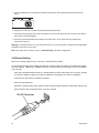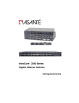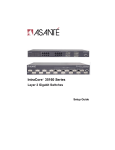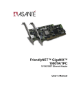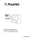
1
IntraCore® 36000 Series
Managed Gigabit Ethernet Switches
Setup Guide
IntraCore 36000 Series
Managed Gigabit Ethernet Switches
Setup Guide
Asanté Technologies, Inc.
821 Fox Lane
San Jose, CA 95131
USA
SALES
800-662-9686 Home/Office Solutions
800-303-9121 Enterprise Solutions
408-435-8388
TECHNICAL SUPPORT
801-566-8991: Worldwide
801-566-3787: Fax
www.asante.com/support
[email protected]
[Default IP Address: 192.168.0.1]
[Default username: root
]
[Default password: Asante
]
Copyright © 2004 Asanté Technologies, Inc. All rights reserved. No part of this document, or any associated artwork,
product design, or design concept may be copied or reproduced in whole or in part by any means without the express
written consent of Asanté Technologies, Inc. Asanté and IntraCore are registered trademarks and the Asanté logo,
AsantéCare, Auto-Uplink, and IntraCare are trademarks of Asanté Technologies, Inc. All other brand names or
product names are trademarks or registered trademarks of their respective holders. All features and specifications
are subject to change without prior notice.
P/N 06-00702-00 Rev.A 5/19/04
2
Setup Guide
Table of Contents
Table of Contents...........................................................................................................................................................3
Chapter 1: Introduction...................................................................................................................................................5
1.1 Features...........................................................................................................................................................5
1.2
1.3
1.4
1.5
Switch Architecture ..........................................................................................................................................7
Network Management Options ........................................................................................................................7
Ports ................................................................................................................................................................7
SFP Slots.........................................................................................................................................................7
Chapter 2: Network Planning .........................................................................................................................................8
2.1 Switch Applications ...........................................................................................................................................8
2.2 Configuration Considerations..........................................................................................................................11
Chapter 3: Hardware Installation and Setup ................................................................................................................12
3.1 Installation Overview.......................................................................................................................................12
3.2 Safety Recommendations ...............................................................................................................................12
3.3 Site Requirements ..........................................................................................................................................13
3.4 Preparing for Installation .................................................................................................................................14
3.5 Unpacking and Inspecting...............................................................................................................................14
3.6 Installing the Switch ........................................................................................................................................15
3.7 Installing an Optional SFP Transceiver ...........................................................................................................17
3.8 Applying Power ...............................................................................................................................................17
3.9 Ethernet Cabling .............................................................................................................................................18
3.10 Connecting to the Console Port ....................................................................................................................19
Chapter 4: Connecting Network Devices .....................................................................................................................20
4.1 Twisted-Pair Devices ......................................................................................................................................20
4.2 Fiber Optic SFP Devices.................................................................................................................................21
4.3 Interpting LEDs ...............................................................................................................................................22
4.4 Connectivity Guidelines...................................................................................................................................23
4.5 Cable Labeling and Connection Records........................................................................................................25
Chapter 5: Configuring the Switch................................................................................................................................26
5.1 Connecting to the Switch ................................................................................................................................26
5.2 Setting an IP Address .....................................................................................................................................27
Asanté IntraCore 36000 Series Managed Gigabit Switches
3
Chapter 6: Understanding the Command Line Interface (CLI) .....................................................................................28
6.1 User Top (User EXEC) Mode..........................................................................................................................28
6.2 Privileged Top (Privileged EXEC) Mode .........................................................................................................28
6.3 Global Configuration Mode .............................................................................................................................29
6.4 Advanced Features Supported within the Command Mode ............................................................................31
6.5 Checking Command Syntax............................................................................................................................32
6.6 Using CLI Command History...........................................................................................................................33
6.7 Using the No and Default Forms of Commands..............................................................................................33
6.8 Using Command-Line Editing Features and Shortcuts ...................................................................................33
Appendix A: Basic Troubleshooting .............................................................................................................................36
A.1 Diagnosing Switch Indicators..........................................................................................................................36
A.2 Power and Cooling Problems .........................................................................................................................36
A.3 Installation ......................................................................................................................................................36
A.4 In-Band Access ..............................................................................................................................................37
Appendix B: Specifications...........................................................................................................................................38
Appendix C: Cables and Pin Assignments...................................................................................................................41
C.1 Twisted-Pair Cable and Pin Assignments.......................................................................................................41
C.2 Pin Assignments for 1000BaseT Pin ..............................................................................................................42
C.3 Cable Testing for Existing Category 5 Cable..................................................................................................43
C.4 Fiber Standards ..............................................................................................................................................43
Appendix D: FCC Compliance and Warranty Statements............................................................................................44
D.1 FCC Compliance Statement...........................................................................................................................44
D.2 Important Safety Instructions..........................................................................................................................44
D.3 IntraCare Warranty Statement........................................................................................................................45
Appendix E. Online Warranty Registration...................................................................................................................46
4
Setup Guide
Chapter 1: Introduction
The IntraCore 36000 Series Managed Gigabit Ethernet Switches are high-performance network switches used to
reduce network congestion and application response times. The 24-port (IC36240) and 48-port (IC36480) have
10/100/1000BaseT ports and four combination ports used for sharing with SFP mini GBICs. The switches also have
an SNMP-based management agent embedded on the main board. This agent supports both in-band and out-ofband access for managing the switch.
These switches have a broad range of features for Layer 2 switching delivering reliability and consistent performance
for network traffic. The switches improve network performance by segregating them into separate broadcast domains
with IEEE 802.1Q compliant VLANs and provide multimedia applications with multicast switching and CoS services.
The IC36240 is a 24-port switch with 20 10/100/1000BaseT ports and 4 combination ports with 10/100/1000BaseT
and SFP MiniGBICs.
The IC36480 is a 48-port switch with 44 10/100/1000BaseT ports and 4 combination ports with 10/100/1000BaseT
and SFP MiniGBICs.
1.1 Features
The IntraCore 36000 Series Managed Gigabit Ethernet Switches support the following features:
1.1.1 Connectivity
24 or 48 10/100/1000 BaseT for Gigabit Ethernet integration into LAN networks.
Auto-negotiation enables each RJ-45 port to automatically select the optimum communication mode, either half
or full duplex, depending on the capability of the attached device. You can also configure the port manually.
Note: A copper Gigabit Ethernet port must use auto-negotiation to determine which link partners will be the master
and slave. It is not possible to force a copper port to 1000 Mbps/full duplex. Any Gigabit device connected to the
switch using copper cabling must support auto-negotiation. A fiber port may use auto-negotiation or may be forced to
1000/full duplex.
Independent RJ-45 10/100/1000BaseT ports with Asanté Auto-Uplink MDI/MDI-X selection.
Unshielded (UTP) cable supported on all RJ-45 ports: Category 3, 4 or 5 for 10 Mbps connections, Category 5 or
5e for 100 Mbps connections, and Category 5 or better for 1000 Mbps connections.
IEEE 802.3 Ethernet, 802.3u Fast Ethernet, 802.3z and 802.3ab Gigabit Ethernet compliance ensures
compatibility with standards-based hubs, network cards and switches.
Asanté IntraCore 36000 Series Managed Gigabit Switches
5
Fiber cable options using SFP ports:
1000BaseSX (MMF) up to 550 m
1000BaseLX (SMF) up to 5 km
1000BaseLH link up to 70 km
1.1.2 Expandability
Provides support for 1000BaseSX, 1000BaseLX, 1000BaseLH, and 1000BaseT SFP transceivers
1.1.3 Performance
Provides 255 port-based VLANs, 4K VLAN ID, private VLAN, 802.1v VLAN, GVRP, and IGMP snooping
Transparent bridging
Switching table with 16K MAC address entries with automatic learning and aging
Store-and-forward switching
Layer 2 Gigabit Ethernet wire-speed switching
Selectable IEEE802.3x flow control, using back pressure for half duplex and IEEE 802.3x for full duplex
Broadcast storm control
Desktop or rack-mountable
External emergency power supply, EPS-36 port
Provides link aggregation with up to 8 trunks that are compatible with IEEE802.3ad and Cisco EtherChannel.
1.1.4 Management
LEDs on the front of the unit for easy troubleshooting
Security features:
User passwords
SNMP access filter
Port security using MAC address filter with notification
Access control lists on L2 and L4
Additional security using RADIUS, TACACS+, SSH/Secure telnet, HTTPS/SSL
Network management agent:
Manages switch in-band or out-of-band
Supports Telnet, SSH, SNMP/RMON and Web-based interface
6
Setup Guide
1.2 Switch Architecture
The Gigabit Ethernet Switches use a wire-speed, non-blocking switching fabric. This permits simultaneous wirespeed transport of multiple packets at low latency on all ports. These switches also feature full-duplex capability on all
ports, which effectively doubles the bandwidth of each connection.
The switches use store-and-forward switching to ensure maximum data integrity. With store-and-forward switching,
the entire packet is received into a buffer and checked for validity before the packet is forwarded.
1.3 Network Management Options
The IntraCore 36000 Series Managed Gigabit Ethernet Switches provide a management agent with both local and
remote management. You can configure or monitor the switch using the embedded management software or by
using SNMP applications. You can manage the switch by a direct connection to the RS-232 console port (out-ofband), or a network connection (in-band) using Telnet, SSH or the on-board web agent.
1.4 Ports
The IC36240 and IC36480 ports use 10/1000/10000BaseT technology. These RJ-45 ports operate at 10 Mbps or 100
Mbps, half or full duplex, or at 1000 Mbps, full duplex. All ports on both switches support automatic MDI/MDI-X
operation, so you can use straight-through cables for all network connections to PCs or servers, or to other switches
or hubs.
Each of these ports supports auto-negotiation, allowing the optimum transmission mode (half or full duplex), and data
rate (10, 100 or 1000 Mbps) to be automatically set. If a device connected to one of these ports does not support
auto-negotiation, the communication mode of that port can be manually configured.
Note: A copper Gigabit Ethernet port must use auto-negotiation to determine which link partners will be the master
and slave. It is not possible to force a copper port to 1000 Mbps/full duplex.
Any Gigabit device connected to the switch using copper cabling must support auto-negotiation.
A fiber port may use auto-negotiation or may be forced to 1000/full duplex.
Each port also supports auto-negotiation of flow control, so the switches can automatically prevent port buffers from
becoming saturated.
1.5 SFP Slots
The Small Form Factor Pluggable (SFP) ports are shared with four RJ-45 ports (ports 21 through 24 in the IC36240
and ports 45 through 48 in the IC36480). In its default configuration, if an SFP transceiver (purchased separately) is
installed in a slot with a valid link on its port, the associated RJ-45 port is disabled and SFP has priority. You can
configure the device to force the use of an RJ-45 port or SFP slot.
Asanté IntraCore 36000 Series Managed Gigabit Switches
7
Chapter 2: Network Planning
A network switch allows simultaneous transmission of multiple packets using segmented architecture.
When network performance is reduced due to congestion at the network access point (for example, the network card
for a high-volume file server), the device experiencing congestion (a server, power user or hub) can be attached
directly to a switched port. Using full-duplex mode doubles the bandwidth of the segment to maximize throughput.
In networks based on repeater (hub) technology, the maximum distance between devices is limited. For Ethernet,
there may be up to four hubs between any pair of stations; for Fast Ethernet, the maximum is two. The switch
removes the distance limitiations by subdividing the network into smaller more manageable segments and linking
them to the larger network.
A switch can be configured in any Ethernet, Fast Ethernet or Gigabit Ethernet network to increase bandwidth using
conventional cabling and network cards.
2.1 Switch Applications
The IntraCore 36000 Series Managed Gigabit Ethernet Switches are designed to segment your network and provide
a wide range of options in setting up network connections and linking VLANs. The switch can operate as a standalone network or in combination with other IntraCore switches in the backbone.
2.1.1 Collapsed Backbone
The IntraCore 36000 Series Managed Gigabit Ethernet Switches are designed for use in growing networks and
networks with legacy equipment. They are used in the following environments:
Mixed Ethernet
Fast Ethernet
Gigabit Ethernet
You can build on these basic configurations or by adding direct full-duplex connections to workstations or servers. For
future expansion, the switches can be connected to another hub or switch using one of the Gigabit Ethernet ports
built into the front panel or a Gigabit Ethernet port on a plug-in SFP transceiver.
As the following figure shows, the 24-port Gigabit Ethernet Switch operating as a collapsed backbone for a small
LAN. It is providing dedicated100 Mbps full-duplex connections to workstations and 1000 Mbps full-duplex
connections to power users and servers.
8
Setup Guide
1
3
5
7
9
11
13
15
17
19
21
23
2
4
6
8
10
12
14
16
18
20
22
24
1000=Yellow 100=Green 10=Flashing Green
21
22
23
24
1
3
5
7
9
11
13
15
17
19
21
23
2
4
6
8
10
12
14
16
18
20
22
24
Link
Power
Act
Diag
Link
RPU
Console
Act
...
Servers
1000 Mbps
Full Duplex
1000=Yellow 100=Green 10=Flashing Green
...
Workstations
1000 Mbps
Full Duplex
...
Workstations
100 Mbps
Full Duplex
2.1.2 Network Aggregation Plan
With 24 or 48 parallel bridging ports (i.e., 24 or 48 distinct collision domains), the Gigabit Ethernet Switch can
collapse a complex network down into a single efficient bridged node, increasing overall bandwidth and throughput.
The following illustration shows that the 10/100/1000BaseT ports on the 24-port Gigabit Ethernet Switch are providing
1000 Mbps connectivity for up to 24 segments through Layer 2 switches. In addition, the switch is also connecting
several servers at 1000 Mbps.
2.1.3 Remote Connection with Fiber Cable
Fiber optic technology provides longer cabling distances than any other media type. A 1000BaseSX (MMF) link can
connect to a site up to 550 meters away, a 1000BaseLX (SMF) link up to 5 km, and a 1000BaseLH link up to 70 km.
This allows a Gigabit Ethernet Switch to serve as a collapsed backbone, providing direct connectivity for a
widespread LAN.
A 1000BaseSX SFP transceiver can be used for a high-speed connection between floors in the same building, and a
1000BaseLX SFP can be used to connect to other buildings in a campus setting. For long-haul connections, a
1000BaseLH SFP transceiver can be used to reach another site up to 70 km away.
The following figure illustrates the 24-port Gigabit Ethernet Switch connecting multiple segments with fiber cable.
Asanté IntraCore 36000 Series Managed Gigabit Switches
9
Headquarters
1
3
5
7
9
11
13
15
17
19
21
23
1000=Yellow 100=Green 10=Flashing Green
21
23
22
24
1
3
5
7
9
11
13
15
17
19
21
23
2
4
6
8
10
12
14
16
18
20
22
24
Link
Power
Act
Diag
Link
RPU
Console
Act
2
4
6
8
10
12
14
5
7
20
22
1000=Yellow 100=Green 10=Flashing Green
24
1000BASE-LX SMF
(5 kilometers)
Remote Switch
3
18
1000BASE-SX MMF
(500 meters)
Server Farm
1
16
9
11
13
15
17
19
21
Remote Switch
23
1000=Yellow 100=Green 10=Flashing Green
Link
21
22
23
24
1
3
5
7
9
11
13
15
17
19
21
23
2
4
6
8
10
12
14
16
18
20
22
24
Power
Act
Diag
Link
RPU
Console
1
3
5
7
9
11
13
15
17
19
21
23
2
4
6
8
10
12
14
16
18
20
22
24
1000=Yellow 100=Green 10=Flashing Green
Act
2
4
6
8
10
12
14
16
18
20
22
Link
1000=Yellow 100=Green 10=Flashing Green
24
21
22
23
24
1
3
5
7
9
11
13
15
17
19
21
23
2
4
6
8
10
12
14
16
18
20
22
24
Power
Act
Diag
Link
RPU
Console
Act
1000=Yellow 100=Green 10=Flashing Green
10/100/1000 Mbps Segments
...
...
2.1.4 VLAN Connections
VLANs are used to organize any group of nodes into separate broadcast domains. VLANs confine broadcast traffic to
the originating group and eliminate broadcast storms in large networks. They provide a secure and efficient network.
VLANs are based on untagged port groups, or traffic can be explicitly tagged to identify the VLAN group to which it
belongs. Untagged VLANs can be used for small networks attached to a single switch. Tagged VLANs should be
used for larger networks, and all the VLANs assigned to the inter-switch links.
Using multiple spanning trees allows VLAN groups to maintain a stable path among all VLAN members. This reduces
the overall amount of protocol traffic crossing the network and provides a shorter reconfiguration time if any link in the
spanning tree fails.
R&D
1
3
5
7
9
11
13
15
17
19
21
23
2
4
6
8
10
12
14
16
18
20
22
24
1000=Yellow 100=Green 10=Flashing Green
VLAN 1
21
22
23
24
1
3
5
7
9
11
13
15
17
19
21
23
2
4
6
8
10
12
14
16
18
20
22
24
Link
Power
Act
Diag
Link
RPU
Console
Act
Tagged
Ports
Tagged Port
Untagged Ports
Finance
VLAN 2
Testing
1000=Yellow 100=Green 10=Flashing Green
VLAN
aware
switch
VLAN
unaware
switch
R&D
Marketing
Finance
Testing
VLAN 3
VLAN 1
VLAN 2
VLAN 4
VLAN 3
Note: When connecting to a switch that does not support IEEE 802.1Q VLAN tags, use untagged ports.
10
Setup Guide
2.2 Configuration Considerations
When planning your network, consider the following:
1.
Full-duplex operation only applies to point-to-point access (for example, when a switch is attached to a
workstation, server or another switch). When the switch is connected to a hub, both devices must operate in
half-duplex mode.
2.
Avoid using flow control on a port connected to a hub. This type of connection may cause dropped or
jammed signals and may degrade overall performance for the segment attached to the hub.
3.
Consider power budget constraints when calculating the maximum cable length for your environment.
2.2.1 Optional Redundant Power Unit
The switches support an optional Redundant Power Unit (RPU) that can supply power to the switch in the event of
failure of the internal power supply.
2.2.2 Power Supply Receptacles
There is one power receptacle on the rear panel of each switch. The standard power receptacle is for the AC power
cord. The receptacle labeled “RPU” is for the optional Redundant Power Unit (RPU).
The following illustration shows the receptacle for the IC36240.
100-240V~, 50-60Hz 2A
RPU
DC IN
12V 8.5A
The following illustration shows the receptacle for the IC36480.
Asanté IntraCore 36000 Series Managed Gigabit Switches
11
Chapter 3: Hardware Installation and Setup
This chapter describes the procedures for rack-mounting, connecting the cables, and powering up the IntraCore
36000 Series Managed Gigabit Ethernet Switch at your site.
3.1 Installation Overview
Follow these steps to install the IntraCore 36000 Series Managed Gigabit Ethernet switch:
Open the box and check the contents. For a complete list of the items included with the switch, see “Unpacking
and Inspecting” section later in this chapter.
Install the switch in an equipment or wall rack, or prepare for desktop placement.
Connect the power cord to the switch and to an appropriate power source.
Connect network devices to the switch.
See the sections below for more detailed installation instructions.
3.2 Safety Recommendations
The following information provides safety guidelines to ensure general safety and to protect the switch from damage.
Note: This information is a guideline and may not include every possible hazard to which you may be exposed. Use
caution when installing this switch.
Only trained and qualified personnel should be allowed to install or replace this equipment
Always use caution when lifting heavy equipment
Keep the switch clean
Keep tools and components off the floor and away from foot traffic
Do not wear rings, chains or other jewelry. Metal objects can heat up and cause serious injury to persons and
damage the equipment.
Do not wear loose clothing. Fasten your tie or scarf and roll up your sleeves.
When working with electricity, follow these guidelines:
Disconnect all external cables before installing or removing the cover
Do not work alone when working with electricity
Always check that the cord has been disconnected from the outlet before performing hardware configuration
Do not tamper with the equipment. Doing so could void the warranty.
Examine the work area for potential hazards (such as wet floors or ungrounded cables)
12
Setup Guide
3.3 Site Requirements
Consider the following site requirements for proper installation.
3.3.1 Environmental Requirements
Choose a clean, dry, dust-free area location. Avoid direct sunlight, heat sources, or areas with high levels of
electromagnetic interference. Failure to observe these limits may cause damage to the switch and may void the
warranty.
3.3.2 Power
Make sure the power source adheres to the following guidelines:
Outlet: Properly grounded, located near the switch, and easily accessible
Power: Auto Switching 90-260 VAC
Frequency range: 50/60 Hz
3.3.3 Cooling and Airflow
The IC36000 switches use internal fans for air-cooling. Do not restrict airflow by covering or obstructing air vents on
the sides of the switch.
Operating Temperature: 32° to 104° F (0° to 40° C)
Relative Humidity: 10% to 90% non-condensing
3.3.4 Rack Mounting
Before mounting the switch in a rack, follow these general precautions:
Size:
Make sure there is adequete space, including clearence and airflow, in the rack to accommodate the
size of the unit.
IC36240: 17.1 x 10.1 x 1.6 inches (434 x 257 x 41 mm)
IC36480: 17.5 x 14.0 x 2.6 inches (445 x 356 x 66 mm)
Temperature: The temperature within a rack assembly may be higher than the ambient room temperature.
Check that the rack-environment temperature is within the specified operating temperature range and remains
below 104°F (40°C).
Clearance: Be sure that no obstructions, such as other equipment or cables, block airflow to or from the vents of
the switch. Be sure there is adequate clearance for servicing the switch.
Mechanical Loading: Do not place any equipment on top of a rackmounted unit.
Circuit Overloading: Be sure that the supply circuit to the rack assembly is not overloaded.
Grounding: Rackmounted equipment should be properly grounded. Particular attention should be given to
supply connections other than direct connections to the mains.
Asanté IntraCore 36000 Series Managed Gigabit Switches
13
3.4 Preparing for Installation
Switches can be mounted in a standard 19-inch equipment rack or on a flat surface. Follow these general precautions
when planning your equipment locations and connections.
The site needs the following:
Centrally located to the devices you want to link
Near a power outlet
Constant temperature within 32° to 104°F (0° to 40°C) and its humidity within 10% to 90%, non-condensing
Adequate space (approximately two inches) on all sides for proper air flow
Accessible for installing, cabling and maintaining the devices
Clearly visible status LEDs
Additional precautions:
Keep the front of the chassis free from obstruction and away from the exhaust air of other equipment. Electrical
equipment generates heat and the ambient room temperature should be enough to cool the equipment to
required operating temperatures.
Make sure twisted-pair cable is always routed away from power lines, fluorescent lighting fixtures and other
sources of electrical interference (for example, radios and transmitters).
Make sure that the unit is connected to a separate grounded power outlet that provides 100 to 240 VAC, 50 to 60 Hz,
is within 2.44 m (8 feet) of each device and is powered from an independent circuit breaker. As with any equipment,
using a filter or surge suppressor is recommended.
3.5 Unpacking and Inspecting
Before you unpack your equipment, examine all shipping containers for damage. If any damage has occured, notify
the shipping carrier immediately. Unpack the unit by removing the packing material and lifiting it from the protective
enclosures. Visually examine the equipment and check the container for parts and accessories. You should have the
following items:
A 24- or 48-port IC 36000 Managed Gigabit Ethernet Switch
Four adhesive foot pads
A Bracket Mounting Kit
two brackets
four screws for attaching the brackets
An AC Power Cord
An RS-232 console cable
This Setup Guide
The User’s Manual on an accompanying CD-ROM
14
Setup Guide
Contact your dealer immediately if any item is missing.
Recommended Tools
You need the following tools and equipment (not included) to install the switch into an equipment rack:
Flat head screwdriver
Phillips head screwdriver
Four mounting screws for each device you plan to install in a rack (not included with the switch)
Antistatic mat or foam
3.6 Installing the Switch
The switch can be mounted in a standard 19-inch equipment rack or placed on a desktop or shelf. Mounting
instructions for each type of site follow.
3.6.1 Mounting the Switch in a Rack
When installing this unit in an empty rack, mount it at the bottom. When mounting this unit in a partially filled rack,
load the rack from the bottom to the top with the heaviest component at the bottom. Follow these steps to properly
install the switch into an equipment rack.
Caution: Before continuing, disconnect all cables from the switch.
To mount the switch onto an equipment rack:
1. Place the switch on a flat, stable surface.
2. Locate a rack-mounting bracket (supplied) and place it over the
mounting holes on one side of the switch.
3. Use the screws (supplied) to secure the bracket (with a Phillips
screwdriver).
4. Repeat the two previous steps on the other side of the switch.
5. Place the switch in the equipment rack.
6. Secure the switch by attaching the mounting brackets onto the equipment rack with the screws supplied with the
unit.
Asanté IntraCore 36000 Series Managed Gigabit Switches
15
Warning: Make sure you support the switch until all the mounting screws for each bracket are secured to the
equipment rack. Failure to do so could cause the switch to fall, which may result in personal injury or damage to the
switch.
When installing multiple switches, mount them in the rack, one above the other, in any order.
When installation is complete, turn to the “Applying Power” section later in this chapter.
3.6.2 Desktop or Shelf Mounting
Follow these steps when planning to use the switch on either a desktop or a shelf:
1. Attach the four adhesive feet to the bottom of the switch.
1000=Y
ellow
2
1
24
4
3
6
5
8
7
100=G
18
reen
20
10=Fla
shing
Green
10
9
14
12
11
13
reen
1000=Y
ellow
100=G
Act
22
24
16
17
15
19
Lin k
Act
21
23
Lin k
RPU
Console
Diag
Pow
er
g Gre
en
shin
10=Fla
23
22
24
22
21
20
18
16
14
23
12
21
10
19
17
8
6
15
4
13
2
11
9
7
5
3
1
2. Set the device on a flat surface near an AC power source, making sure there are at least two inches of space on
all sides for proper air flow.
3. Place each device squarely on top of the one below, in any order.
When installation is complete, turn to the “Applying Power” section later in this chapter.
16
Setup Guide
3.7 Installing an Optional SFP Transceiver
This section describes installing the SFP transceiver.
To install an SFP transceiver, do the following:
1. Select an appropriate SFP transceiver type determined by the network and cabling requirements.
2. Insert the transceiver with the optical connector facing outward and the slot connector facing down. The SFP
transceivers are keyed to help establish the correct position.
3. Slide the SFP transceiver into the slot until it clicks into place.
1
2
3
1000=Y
ellow
100=
Green
10=F
lashin
7
g Gree
9
n
11
5
13
4
6
8
10
15
17
19
21
12
14
1000=Y
16
ellow
18
100=
20
Green
10=F
lashin
g Gree
n
23
Lin k
Ac t
22
24
Lin k
Ac t
Powe
r
Diag
RPU
Cons
ole
3.7.1 Hot Swapping Feature
The hot-swapping feature lets you install and replace the SFP transceivers while the system is operating; you do not
need to disable the software or shut down the system power.
Caution: When replacing an SFP transceiver, you must always disconnect the network cable before removing a
transceiver.
3.8 Applying Power
The system’s front panel LED display allows you to monitor the status of the switch. For LED information specific to
the switch’s model, see the “Interpreting LEDs” section in Chapter 4.
The back panel contains a 12 VDC jack for redundant power (optional) and the primary power socket.
Follow these steps to connect the switch.
Asanté IntraCore 36000 Series Managed Gigabit Switches
17
1. Use the supplied power cord and plug the female end directly into the receptacle located at the back of the
device.
100-240V~,50-60HZ 2A
2. Plug the other end of the cord into a properly grounded electrical outlet.
3. Check the front-panel LEDs as the device is powered on to be sure the Power LED is lit. If not lit, check that the
power cable is correctly plugged in.
4. Connect the optional redundant power supply to the switch and to an AC power source by following the
instructions for the unit.
Warning: For International use: if you use power other than AC, you must use power cords that meet the appropriate
standards for the power you are using.
Note: If the power does not come on, refer to “Troubleshooting” information in Appendix A.
3.9 Ethernet Cabling
Based on the existing equipment in your network you need the following cables.
To ensure proper operation when installing the switch into a network, make sure that the current cables are suitable
with either 10BaseT, 100BaseTX or 1000BaseT operation. Check the following criteria against the current installation
of your network:
Cable type: Unshielded twisted pair (UTP) or shielded twisted pair (STP) cables with RJ-45 connectors; Category
3 or better for 10BaseT, Category 5 or better for 100BaseTX, and Category 5e or better for 1000BaseT
Protection from radio frequency interference emissions
Electrical surge suppression
Separation of electrical wires (switch related or other) and electromagnetic fields from data-based network wiring
Safe connections with no damaged cables, connectors or shields
RJ-45 Connector
18
Setup Guide
When attaching a workstation to the switch, a standard straight through CAT5 cable may be used. No crossover
cable is needed on the MDI/MDI-X ports.
3.10 Connecting to the Console Port
The DB-9 serial port located on the front panel is used to connect to the switch for out-of-band console configuration.
The on-board configuration program can be accessed from a terminal or a PC running a terminal emulation program.
The pin assignments used to connect to the serial port are provided in the following tables.
3.10.1 Wiring Map for Serial Cable
The following table describes the serial cable wiring information.
Switch’s 9-Pin Serial Port
Null Modem
PC’s 9-Pin DTE Port
2 RXD (receive data)
Å
3 TXD (transmit data)
3 TXD
Æ
2 RXD (receive data)
5 SGND (signal ground)
---
5 SGND (signal ground)
The serial port configuration requirements are as follows:
Default Baud rate—auto-sensing (9.6 to 115K)
Character Size—8 Characters
Parity—None
Stop bit—One
Data bits—8
Asanté IntraCore 36000 Series Managed Gigabit Switches
19
Chapter 4: Connecting Network Devices
The switch is designed to interconnect multiple segments (or collision domains). It can be connected devices using
optional SFP transceivers to network cards in PCs and servers, to hubs, routers or other switches.
4.1 Twisted-Pair Devices
Each device requires an unshielded twisted-pair (UTP) cable with RJ-45 connectors at both ends. Use Category 5, 5e
or 6 cable for 1000BaseT connections, Category 5 for 100BaseTX connections, and Category 3, 4 or 5 for 10BaseT
connections.
4.1.1 Cable Guidelines
The RJ-45 ports on these switches support automatic MDI/MDI-X pinout configuration, so you can use standard
straight-through twisted-pair cables to connect to any other network device (PCs, servers, switches, routers or hubs).
See “Appendix C” for further information on cabling.
Caution: Do not plug a phone jack connector into an RJ-45 port. Doing this will damage the switch. Use only
twisted-pair cables with RJ-45 connectors that conform to FCC standards.
4.1.2 Connecting to PCs, Servers, Hubs and Switches
1. Attach one end of a twisted-pair cable segment to the device’s RJ-45 connector.
2. When device is a PC card and the switch is in the wiring closet, attach the other end of the cable segment to a
modular wall outlet that is connected to the wiring closet. (See “Connectivity Guidelines” later in this chapter.)
Otherwise, attach the other end to an available port on the switch.
3. Make sure each twisted pair cable does not exceed 328 ft (100m) in length.
Note: Using flow control on a port connected to a hub may degrade performance.
4.
20
As each connection is made, the Link LED (on the switch) corresponding to each port lights up to indicate
that the connection is complete. (For more information, see “Interpreting LEDs” later in this chapter.)
Setup Guide
4.1.3 Network Wiring Connections
Today, the punch-down block is an integral part of many of the newer equipment racks. It is actually part of the patch
panel. To make connections in the wiring closet, do the following:
1. Attach one end of a patch cable to an available port on the switch, and the other end to the patch panel.
2. Attach one end of a cable segment to the back of the patch panel where the punch-down block is located, and
the other end to a modular wall outlet.
3. Label the cables to simplify future troubleshooting.
Equipment Rack
(side view)
Network Switch
w it ch 10 /1 0 0
6724L 3
ES4524C
Punch-Down Block
Patch Panel
Wall
4.2 Fiber Optic SFP Devices
An optional Gigabit SFP transceiver (1000BaseSX, 1000BaseLX or 1000BaseLH) can be used for a backbone
connection between switches, or for connecting to a high-speed server.
Each multimode fiber optic port requires 50/125 or 62.5/125 micron multimode fiber optic cabling with an LC
connector at both ends.
Each single-mode fiber port requires 9/125-micron single-mode fiber optic cable with an LC connector at both ends.
Warning: The lasers used to transmit signals over fiber optic cable are compliant with the requirements of a Class 1
Laser Product and in normal operation are safe. It is still recommended you not look directly at a transmit port.
Asanté IntraCore 36000 Series Managed Gigabit Switches
21
1. Remove and keep the LC port’s rubber cover. When not connected, the rubber cover should be replaced to
protect the optics.
2. Check that the fiber terminators are clean. You can clean the cable plugs by wiping them gently with a clean
tissue or cotton ball moistened with a little ethanol. Dirty fiber terminators on fiber cables will impair the quality of
the light transmitted through the cable and lead to degraded performance on the port.
3. Connect one end of the cable to the LC port on the switch and the other end to the LC port on the other device.
Since LC connectors are keyed, the cable can be attached in only one orientation.
4. As a connection is made, check the Link LED on the switch corresponding to the port to be sure that the
connection is valid. (For more LED information, see the following “Interpreting LEDs” section.)
1000=Green 10/100=Yellow
24
1
3
5
7
9
11
13
15
17
19
21
23
2
4
6
8
10
12
14
16
18
20
22
24
Link
/Act
Power
FDX
Diag
Link
/Act
RPU
Console
FDX
1000=Green 10/100=Yellow
The 1000BaseSX, 1000BaseLX and 1000BaseLH fiber optic ports operate at 1 Gbps full duplex, with autonegotiation of flow control. The maximum length for fiber optic cable operating at Gigabit speed depends on the fiber
type as listed under “1000 Mbps Gigabit Ethernet Cabling” later in this chapter.
4.3 Interpreting LEDs
The LEDs are located on the front panel. This figure is an example of the IC36240 Port LEDs.
Console
Power
RPU
Diag
46
45
47
48
This figure is an example of the IC36480 Port LEDs.
1
2
3
4
5
6
7
8
9
10
11
12
4.3.1 IC36240 and IC36480 Status LEDs
The following table lists the LEDs and describes the status lights.
LED
Condition
Status
On/Flashing Amber
The port has a valid 10 or 100 Mbps link. Flashing indicates activity.
On/Flashing Green
The port has a valid 1000 Mbps link. Flashing indicates activity.
RJ-45 Ports
Link/Activity
22
Setup Guide
Full-Duplex (IC36240
only)
On/Green
The port is operating in full-duplex mode.
Off
The port is operating in half-duplex mode.
On/Green
An SFP transceiver port has established a valid 1000 Mbps network
connection. The associated RJ-45 port is disabled.
Off
An SFP transceiver port has no valid link or the link has failed. The
associated RJ-45 port is enabled.
SFP Transceiver Slots
(Ports 21-24, 45-48)
4.3.2 IC36240 and IC36480 System LEDs
The following table lists the system LED descriptions.
LED
Condition
Status
Power
On/Green
Indicates internal power is operating normally.
On/Amber
Indicates internal power supply fault.
Off
Indicates power is off or the device has failed.
Flashing Green
Indicates the system self-diagnostic test is running.
On/Green
Indicates the system self-diagnostic test is complete.
On/Amber
Indicates the test has detected a fault. Contact Technical
Support.
On/Green
The redundant power unit is receiving power.
On/Amber
The redundant power unit is not receiving power.
Off
There is no redundant power unit.
CPU
EPS
4.4 Connectivity Guidelines
When adding hubs (repeaters) to your network, follow the connectivity rules listed in the manuals for these products.
Since the switch breaks the path for connected devices into separate collision domains, you should not include the
switch or connected cabling in your calculations for cascade length involving other devices.
4.4.1 1000BaseT Cable Requirements
When all four wire pairs are connected, all Category 5 UTP cables used for 100BaseTX connections also work with
1000BaseT. All critical connections and new cable installations should only use Category 5e or Category 6 cable.
The Category 5e specification includes test parameters that are only recommendations for Category 5. When
preparing existing Category 5 cabling for running 1000BaseT, a simple test of the cable installation is required to be
sure that it complies with the IEEE 802.3ab standards.
Asanté IntraCore 36000 Series Managed Gigabit Switches
23
4.4.2 1000 Mbps Gigabit Ethernet Cabling
The following tables show cable types, maximum lengths, required connectors and bandwidth as applicable.
1000BaseT Gigabit Ethernet Cable Length
Cable Type
Maximum Length
Connector
Category 5, 5e, 6 100-ohm UTP
328 ft (100 m)
RJ-45
1000BaseSX Gigabit Ethernet Cable Length
Fiber Size
Fiber Bandwidth
Range
Connector
62.5/125 micron multimode fiber
160 MHz/km
7-722 ft (2-220 m)
LC
200 MHz/km
7-902 ft (2-275 m)
LC
400 MHz/km
7-1641 ft (2-500 m)
LC
500 MHz/km
7-1805 ft (2-550 m)
LC
7 ft - 3.2 mi (2 m - 5 km)
LC
7 ft - 43.5 mi (2 m - 70 km)
LC
50/125 micron multimode fiber
1000Base-LX Gigabit Ethernet Cable Length
9/125 micron single-mode fiber
N/A
Maximum 1000BaseLH Gigabit Ethernet Cable Length
9/125 micron single-mode fiber
N/A
4.4.3 100 Mbps Fast Ethernet Cabling
The following table shows the connection types, cables, maximum lengths and required connectors.
Connection Type
Cable
Length
Connector
100BaseTX
Category 5 or better 100ohm UTP
328 ft (100 m)
RJ-45
4.4.4 10 Mbps Ethernet Cabling
The following table shows the cable, maximum length and required connectors.
Cable
Length
Connector
Twisted Pair, Categories 3, 4, 5 or better 100-ohm UTP
328 ft (100 m)
RJ-45
24
Setup Guide
4.5 Cable Labeling and Connection Records
When planning a network installation, it is essential to label and record where each cable is connected. This helps
you locate inter-connected devices, isolate faults and change your topology.
To manage the physical implementations of your network, follow these guidelines:
Clearly label the opposing ends of each cable.
Draw a map of the location of all network-connected equipment using your building’s floor plans. For each piece
of equipment, identify devices on the connection.
Note the length of each cable and the maximum cable length supported by the switch ports.
Use a location-based key when assigning prefixes to your cable labeling.
Use sequential numbers for cables that originate from the same equipment.
Name racks to help differentiate among them.
Label each piece of equipment.
Display a copy of your equipment map, including keys to all abbreviations, at each equipment rack.
Asanté IntraCore 36000 Series Managed Gigabit Switches
25
Chapter 5: Configuring the Switch
This chapter takes you through the steps required to initially connect the switch to a console, set up initial passwords,
configure an IP address and restore factory defaults.
5.1 Connecting to the Switch
The switch includes a built-in network management agent. The agent offers a variety of management options,
including Simple Network Management Protocol (SNMP), RMON and a web-based interface. You can connect a
terminal directly to the switch for configuration and monitoring via a command line interface (CLI).
Note: The IP address for this switch is unassigned by default. To change this address, see “Setting an IP Address”
later in this chapter.
The switch’s HTTP web agent allows you to configure switch parameters, monitor port connections and display
statistics using a standard Web browser such as Internet Explorer 5, Netscape 6, Apple Safari 1.2, Mozilla Firefox 0.8
or later, using Windows Me/2000/XP, Mac OS X 10.3 or Linex. The recommended screen resolution is 1024 x 768 or
higher. You can access the switch’s web management interface from any computer attached to the network.
Access the CLI by using a direct connection to the RS-232 serial console port on the switch, or remotely by a Telnet
connection over the network.
The management agent also supports SNMP. The SNMP agent permits the switch to be managed from any system
in the network using network management software such as HP OpenView.
The switch’s web interface, CLI and SNMP agent allow you to perform different management functions, including:
Set user names and passwords
Set an IP interface for a management VLAN
Configure SNMP parameters
Enable/disable any port
Set the speed/duplex mode for any port
5.1.1 Setting Passwords
Note: If this is your first time logging in to the switch, the following login information is the standard default:
[Default IP Address: 192.168.0.1]
[Default username: root
]
[Default password: Asante
]
You should define new usernames and passwords using the “username” command.
Passwords can consist of up to eight alphanumeric characters and are case sensitive. To prevent unauthorized
access to the switch, set the passwords as follows:
1. Open the console interface and type the default user name root and password Asante to access the Privileged
Exec level.
2. Type configure and press Enter.
26
Setup Guide
3. Type username guest password 0 [p asswo rd] where passw ord is your new password. Press Enter.
Switch> enable
Password: <no password by default; press Enter>
Switch# configure
Switch(config)#username admin password 0 [password ]
Switch(config)# admin Password
Switch(config)# exit
5.2 Setting an IP Address
You must establish IP address information for the switch to obtain management access through the network. Do this
in either of the two following ways:
Manual — You have to input the information, including IP address and subnet mask. If your management station is
not in the same IP subnet as the switch, you also need to specify the default gateway.
Dynamic — The switch sends IP configuration requests to BOOTP or DHCP address allocation servers on the
network.
5.2.1 Manual Configuration
You can manually assign an IP address to the switch. You may also need to specify a default gateway that resides
between this device and management stations that exist on another network segment. Valid IP addresses consist
of four decimal numbers, 0 to 255, separated by periods.
5.2.2 Dynamic Configuration
If you select the “bootp” or “dhcp” option, IP is enabled but does not function until a BOOTP or DHCP reply is received.
You need to use the “ip dhcp restart client” command to broadcasting service requests. Requests are sent
periodically in an effort to obtain IP configuration information. BOOTP and DHCP values can include the IP address,
subnet mask, and default gateway.
When “bootp” or “dhcp” is saved to the startup-configuration file, at launch the switch broadcasts service requests.
To automatically configure the switch by communicating with BOOTP or DHCP address allocation servers on the
network, complete the following steps:
1. From the Global Configuration mode prompt, type interface vlan 1 to access the interface-configuration mode.
Press Enter.
2. At the interface-configuration mode prompt, use one of the commands in the following table:
Command
Purpose
ip address dhcp
Obtains IP settings using DHCP
ip address bootp
Obtains IP settings using BOOTP
ip dhcp restart client
Starts broadcasting service requests
Asanté IntraCore 36000 Series Managed Gigabit Switches
27
Chapter 6: Understanding the Command Line Interface (CLI)
The switch utilizes Command Line Interface (CLI) to provide access to several different command modes. Each
command mode provides a group of related commands.
After logging into the system, you are automatically at the privileged (privileged EXEC) mode. At this level, you can
perform general tasks and access the global configuration mode to setup and maintain specific modes (for example,
interface, IP and VLAN configuration). Almost every configuration command also has a no form. You can use the no
form to disable a feature or function. For example, when ARP is enabled enter no arp to disable the ARP table.
Document Conventions
Command descriptions use the following conventions:
Square brackets ([ ]) indicate optional elements
Boldface indicates commands and keywords that are entered literally as shown
Italics indicate arguments for which you supply values
Access Each Command Mode
The following sections describe how to access each of the CLI command modes:
Privileged Top Mode: Switch#
Global Configuration Mode: Switch(config)#
Interface Configuration Mode: Switch(config-if)#
6.1 User Top (User EXEC) Mode
After you log in to the switch, you are automatically into the privileged exec command mode.:
Switch#
The default host name is Switch. Use the setup command to change the name of the device.
The user EXEC commands available at the user level are a subset of those available at the privileged level. These
commands allow you to connect to remote devices, change terminal settings on a temporary basis, perform basic
tests and show system information.
6.2 Privileged Top (Privileged EXEC) Mode
Because many of the privileged commands set the system configuration parameters, access can be password
protected to prevent unauthorized use. The privileged command set includes commands contained in user EXEC
mode, including the configure command where you can access the remaining command modes.
Before allowing access to privileged EXEC mode, you are prompted for a password. If an enable password has not
been set, the enable mode can only accessed through the console. You can enter the enable password global
configuration command to set the password that restricts access to privileged mode.
28
Setup Guide
To return to user EXEC mode, use the disable command.
The privileged EXEC commands allow you to change terminal settings on a temporary basis, perform basic tests and
list system information. To list the commands available in top mode, enter a question mark (?) at the prompt.
Switch# ?
calendar
clear
configure
copy
delete
dir
disable
disconnect
dot1x
exit
help
ip
ping
quit
reload
show
spanning-tree
whichboot
Date information
Reset functions
Enter configuration mode
Copy from one file to another
Delete a file
List files on a filesystem
Turn off privileged commands
Disconnect
Configure 802.1x
Exit from privilege EXEC mode
Description of the interactive help system
Internet protocol
Send echo messages
Exit a CLI session
Halt and perform a warm restart
Show information
Specify spanning tree configuration
Determine boot files
Caution: You must save any changes you make in running configuration to the startup configuration file if you want
those changes to remain after a system reload. From the privileged level, configurations can be saved using the write
command, or by using the copy running-config startup-config command.
6.3 Global Configuration Mode
From the privileged level, you can access global configuration mode. Global configuration commands apply to
features that affect the system as a whole. Commands to enable a particular switching function are also part of this
mode. To enter the global configuration mode, use the configure command.
The following example shows how to access global configuration mode and list global configuration commands.
Command
Purpose
Switch# configure
From privileged EXEC mode, enters global configuration mode.
Switch(config)# ?
Lists the global configuration commands.
Use one of the following commands to exit global configuration mode and return to privileged EXEC mode:
Command
Purpose
Exit
end
Ctrl-Z
Any of these command exits and returns to the previous mode.
Asanté IntraCore 36000 Series Managed Gigabit Switches
29
To list the commands available in global configuration mode, enter a question mark (?) at the prompt, as shown in the
following example. Enter a question mark (?) after a command to see all the options for that command.
Switch# configure
Switch(config)# ?
access-list
authentication
boot
bridge-ext
clock
dot1x
enable
end
exit
help
hostname
interface
ip
jumbo
line
logging
mac-address-table
management
map
no
prompt
protocol-vlan
pvlan
queue
radius-server
snmp-server
sntp
spanning-tree
tacacs-server
username
vlan
Access lists
Authentication method
Boot Commands
Bridge extension
Clock
Configure 802.1x
Modify enable password parameters
Exit from configure mode
Exit from global configure mode
Description of the interactive help system
Set system's network name
Into the privileged interface configuration mode
Global IP configuration subcommands
Specify jumbo status
Into the privileged line configuration mode
Modify message logging facilities
Set configuration of the address table
Specify management ip filter
Map priority
Negate a command or set its defaults
Set system's prompt
Protocol-VLAN Global Configuration Commands
Config private VLAN
Assign priority queues
Login by radius server
Modify SNMP parameters
Sntp
Enable spanning tree
Login by tacacs server
Establish User Name Authentication
Switch VLAN Virtual Interface
From global configuration mode, you can access three interface configuration modes: The Ethernet, Port-Channel
and VLAN commands.
6.3.1 Interface Configuration Mode
You can enable most features on a per-interface basis. Interface configuration commands modify the operation of an
interface such as an Ethernet or VLAN. Interface configuration commands always follow an interface global
configuration command, which defines the interface type as Ethernet or VLAN.
The following example shows configuring port-channel 1. The new prompt, Switch(config-if)#, indicates interface
configuration mode. In this example, the user asks for help by requesting a list of commands.
Switch(config)# interface port-channel 1
Switch(config-if)# ?
capabilities
Configure the capabilities
description
Add description to the port-channel
end
Exit from configure mode
exit
Exit from port-channel configure mode
flowcontrol
Enable flow control
30
Setup Guide
garp
help
interface
lacp
map
negotiation
no
protocol-vlan
queue
rate-limit
shutdown
spanning-tree
speed-duplex
switchport
Garp property
Description of the interactive help system
Into the privileged interface configuration mode
Lacp configuration
Map priority
Negotiation
Negate a command or set its defaults
Protocol-VLAN interface configuration commands
Assign priority queues
Config rate-limit
Shutdown the selected interface
Specify spanning tree configuration
Configure speed and duplex operation
Configure switching mode characteristics
6.4 Advanced Features Supported within the Command Mode
Enter a question mark (?) at the system prompt to display a list of commands available for each command mode.
Using the context-sensitive help feature you can also get a list of commands, associated keywords and arguments.
To get help specific to a command mode, a command, a keyword or an argument, type one of the following:
Command
Purpose
Help
Obtain a brief description of the help system in any command mode.
?
Obtain a list all commands available for a command or mode.
When using context-sensitive help, the space (or lack of a space) before the question mark (?) is significant.
To obtain a list of commands that begin with a particular character sequence, type in those characters followed
immediately by the question mark (?).
To get help with syntax, list keywords or arguments, enter a question mark (?) in place of a keyword or argument.
Include a space before the question mark (?).
You can abbreviate commands and keywords to the number of characters that allow a unique abbreviation. For
example, you can abbreviate the configure command by typing config or con. Because the shortened form of the
command is unique, the switch executes the command.
Enter the help command (which is available in any command mode) for a brief description of the help system:
Switch# help
Help may be requested at any point in a command by entering
a question mark '?'. If nothing matches, the help list will
be empty and you must backup until entering a '?' shows the
available options.
Two styles of help are provided:
1. Full help is available when you are ready to enter a
command argument (e.g. 'show ?') and describes each possible
argument.
2. Partial help is provided when an abbreviated argument is entered
and you want to know what arguments match the input
(e.g. 'show br?').
Asanté IntraCore 36000 Series Managed Gigabit Switches
31
As described in the help command output, you can enter a partial command name and a question mark (?) to obtain
a list of commands beginning with a particular character set.
Example of Context Sensitive Help
The following illustrates how the context-sensitive help feature creates an access list from the configuration mode.
Enter the letters “co” at the system prompt followed by a question mark (?). Do not leave a space between the last
letter and the question mark (?). The system provides the commands that begin with co.
Switch# co?
configure
copy
Switch# co
Enter configuration mode
Copy from one file to another
Enter the copy command followed by a space and a question mark (?) to list the command’s keyword(s) and a brief
explanation:
Switch# copy ?
file
running-config
startup-config
tftp
unit
Copy
Copy
Copy
Copy
Copy
from
from
from
from
from
file system
current system configuration
startup configuration
tftp server
device unit
Uppercase letters represent variables. For example, after entering dir config ?, the system returns the prompt for the
new name, represented by WORD. Variable IP addresses are shown as the uppercase letters A.B.C.D.
Switch#dir ?
<1-1>:
Unit number
boot-rom: Boot ROM image
config:
Configuration file
opcode:
Runtime code
<cr>
Switch#dir config ?
WORD File name
<cr>
6.5 Checking Command Syntax
The CLI user interface provides an error indicator: a caret symbol (^). The caret symbol appears at the point in the
command string where you have entered an incorrect letter, command, keyword or argument.
The following example shows an invalid entry:
Switch(config)# manageement
^
% Invalid input detected at '^' marker.
Because more than one command begins with the letters en, the following example shows that the command is
unknown or ambiguous.
Switch(config)# en
% Ambiguous command.
The following example shows an incomplete command.
32
Setup Guide
Switch(config)# username
% Command incomplete.
6.6 Using CLI Command History
The CLI provides a history or record of commands entered in the current mode. This is useful when recalling long or
complex commands or entries. Use one of the following to recall commands from the history buffer:
Keystrokes/Command
Purpose
Press Ctrl-P or the up
arrow key
Recall commands in the history buffer, beginning with the most recent command.
Repeat the key sequence to recall successively older commands.
Press Ctrl-N or the
down arrow key
Return to recent commands in the history buffer after recalling commands with Ctrl-P or
the up arrow key. Repeat the key sequence to recall successively more recent
commands.
show history
While in EXEC mode, list the last several commands entered.
6.7 Using the No and Default Forms of Commands
Almost every switch configuration command has an opposite no form that negates or reverses a command. Use the
no form to disable a function previously enabled. To re-enable a disabled function, or to enable a function that is
disabled by default, use the command without the no keyword.
6.8 Using Command-Line Editing Features and Shortcuts
Different shortcuts and editing features are enabled using the CLI and are described in this section.
6.8.1 Moving Around on the Command Line
To make corrections or changes and to move the curser on the command line, use the following keystrokes:
Keystrokes
Purpose
Press Ctrl-B or the left arrow
Move the cursor back one character.
Press Ctrl-F or the right arrow
Move the cursor forward one character.
Press Ctrl-A
Move the cursor to the beginning of the command line.
Press Ctrl-E
Move the cursor to the end of the command line.
Press Esc B
Move the cursor back one word.
Press Esc F
Move the cursor forward one word.
Note: The arrow keys function only on ANSI-compatible terminals such as VT100s.
Asanté IntraCore 36000 Series Managed Gigabit Switches
33
6.8.2 Completing a Partial Command Name
To have the system complete an entry, press the Tab key. If the keyboard does not have a Tab key, press Ctrl-I. The
following example shows typing the letters conf and using Tab key, to complete the command:
Switch# conf<Tab>
Switch# configure
If you enter a set of characters that indicates more than one command, the command is not executed. The system
returns a list of all possible commands.
You may also enter a question mark (?) to obtain a list of commands that begin with that set of characters. Do not
leave a space between the last letter entered and the question mark (?). To get commands in privileged mode that
start with co, use the following method:
Switch# co?
Configure copy
6.8.3 Editing Command Lines That Wrap
The editing feature allows the text to wrap around and continue on the next line. When the cursor reaches the right
margin, the command line shifts eight spaces to the left. You cannot see the first eight characters of the line, but you
can scroll back and check the syntax at the beginning of the command. To scroll back, use the following command:
Keystrokes
Purpose
Press Ctrl-B or left
arrow
Return to the beginning of a command line by repeatedly pressing these keys to verify
that you have correctly entered a lengthy command.
Ctrl-A
Return directly to the beginning of the line.
Note: The arrow keys function only on ANSI-compatible terminals such as VT100.
In the following example, the access-list command entry extends beyond one line. When the cursor first reaches the
end of the line, the line is shifted eight spaces to the left and redisplayed. The dollar sign ($) indicates that the line
scrolled to the left. Each time the cursor reaches the end of the line, it is again shifted eight spaces to the left.
Switch(config)# access-list 101 permit icmp 192.168.123.0 0.0.0.255 192
Switch(config)# $ st 101 permit icmp 192.168.123.0 0.0.0.255 192.168.0.1
When you have completed the entry, press Ctrl-A to check the complete syntax before pressing Enter to execute the
command. The dollar sign ($) appears at the end of the line to indicate that the line scrolled to the right:
Switch(config)# access-list 101 permit icmp 192.168.123.0 0.0.0.255 192$
Use line wrapping in combination with the history command to recall and modify previous complex command entries.
6.8.4 Deleting Entries
Use any of the following commands to delete command entries if you make a mistake or change your mind:
34
Setup Guide
Keystrokes
Purpose
Press Delete or Backspace
Delete the character to the left of the cursor.
Press Ctrl-D
Delete the character at the cursor.
Press Ctrl-K
Delete all characters from the cursor to the end of the command line.
Press Ctrl-U or Ctrl-X
Delete all characters from the cursor to the beginning of the command line.
Press Ctrl-W
Delete the word to the left of the cursor.
Press Esc D
Delete from the cursor to the end of the word.
6.8.5 Scrolling Down a Line or a Screen
When using a command that lists more information than fits the screen, the prompt --More-- appears at the bottom of
the screen. Whenever the More prompt is displayed, use the following keystrokes to view the next line or screen:
Keystrokes
Purpose
Press Return
Scroll down one line.
Press Spacebar
Scroll down one screen.
6.8.6 Redisplaying the Current Command Line
If you are entering a command and the system interrupts your current command, use the following command to recall
the last command line entry:
Keystrokes
Purpose
Press Ctrl-L or Ctrl-R
Redisplay the current command line.
6.8.7 Transposing Mistyped Characters
To transpose mistyped characters, use the following command:
Keystrokes
Purpose
Press Ctrl-T
Transpose the character to the left of the cursor with the character next to the cursor.
6.8.8 Controlling Capitalization
To toggle between uppercase and lowercase letters, use the following command:
Keystrokes
Purpose
Press Esc C
Capitalize at the cursor. Press Esc C or Alt-C again to return to lowercase letters.
Asanté IntraCore 36000 Series Managed Gigabit Switches
35
Appendix A: Basic Troubleshooting
In the event that the switch does not operate properly, follow the troubleshooting tips below. If you need more help,
contact Asanté’s technical support at www.asante.com/support.
A.1 Diagnosing Switch Indicators
Refer to the following troubleshooting chart for information about the diagnostic LEDs.
Problem
Possible Solutions
Power LED is not lit
LED is off during system initialization.
Check the power connection. Plug the power cord into another known
working AC outlet.
The primary power supply has failed. Install the optional emergency
power supply and have the primary power supply serviced as soon as
possible.
Link LED is not lit
Verify that the switch and attached device are powered on.
Check the connection between the switch and corresponding device.
Verify that the proper cable type is used and the length does not exceed
specified limits.
Check the adapter on the attached device and cable connections for
possible defects. Replace the defective adapter or cable if necessary.
Power LED is Amber
Internal power supply has failed.
Contact your local dealer for assistance.
Diag LED is Amber
Power cycle the switch to try to clear the condition.
Contact your dealer for assistance.
A.2 Power and Cooling Problems
If the power indicator does not turn on when the power cord is plugged in, you may have a problem with the power
outlet, power cord or internal power supply. However, if the unit powers off after running for a while, check for loose
power connections, power losses or surges at the power outlet and verify that the fans on the unit are unobstructed
and running prior to shutdown. If you still cannot isolate the problem, then the internal power supply may be defective.
A.3 Installation
Verify that all system components have been properly installed. If one or more components appear to be
malfunctioning (for example, the power cord or network cabling), test them in an alternative environment where you
are sure that all the other components are functioning properly.
36
Setup Guide
A.4 In-Band Access
You can access the management agent in the switch from anywhere within the attached network using Telnet, a web
browser, or other network management software tools. Do this by configuring the switch with a valid IP address,
subnet mask and default gateway. If you cannot establish a link to the management agent, verify that there is a valid
network connection, you entered the correct IP address and that the port through which you are connecting to the
switch has not been disabled. If it has not been disabled, then check the network cabling that runs between the
remote location and the switch.
Caution: The management agent can accept up to four simultaneous Telnet sessions. If you are at maximum
number of sessions, an additional Telnet connection will not be able to log into the system.
Asanté IntraCore 36000 Series Managed Gigabit Switches
37
Appendix B: Specifications
The sections below list the features and product specifications for the IntraCore 36000 Series Managed Gigabit
Ethernet switches.
Physical Characteristics
Ports
IC36240: 24 10/100/1000BaseT, with auto-negotiation; 4 Combination Ports (RJ45/SFP), 1000 Mbps only
IC36480: 48 10/100/1000BaseT, with auto-negotiation; 4 Combination Ports (RJ45/SFP), 1000 Mbps only
Network Interface
Ports 1-24/48: RJ-45 connector, auto MDI/X
10BaseT: RJ-45 (100-ohm, UTP cable; Categories 3, 4, 5)
Maximum Cable Length - 328 ft (100 m)
100BaseTX: RJ-45 (100-ohm, UTP cable; Category 5)
Maximum Cable Length - 328 ft (100 m)
1000BaseT: RJ-45 (100-ohm, UTP or STP cable; Category 5, 5e or 6)
Maximum Cable Length - 328 ft (100 m)
Buffer Architecture
1 Mbyte
Aggregate Bandwidth
IC36240: 48 Gbps
IC36480: 96 Gbps
Switching Database
16K MAC address entries
LEDs
System: Power (Power Supply), Diag (Diagnostic), RPU (Redundant Power Unit)
Port: Link/Act (Link/Activity), IC36240 only: FDX (Full Duplex/Half Duplex)
Weight
IC36240: 9.4 lbs (4.3 Kg)
IC36480: 12.9 lbs (5.8 Kg)
38
Setup Guide
Size
IC36240: 17.4 x 12.2 x 1.8 in (44.0 x 31 x 4.4 cm)
IC36480: 17.4 x 16.4 x 1.8 in (44.0 x 41.5 x 4.4 cm)
Temperature
Operating: 32 to 104˚ F (0 to 40˚ C)
Humidity
Operating: 10% to 90% (non-condensing)
AC Input
100 to 240 V, 50-60 Hz, 2A
Power Supply
Internal, auto-ranging transformer: 90 to 240 VAC, 47 to 63 Hz
External, supports connection for 14-pin redundant power unit
Power Consumption
IC36240: 70 Watts maximum
IC36480: 105 Watts maximum
Maximum Current
IC36240: 0.6 A @ 110 VAC
0.3 A @ 240 VAC
IC36480: 1.2 A @ 110 VAC
0.6 A @ 240 VAC
Switch Features
Forwarding Mode
Store-and-forward
Throughput
Wire speed
Flow Control
Full Duplex: IEEE 802.3x
Half Duplex: Back pressure
Management Features
In-Band
Telnet, HTTP or SNMP manager. Software loading TFTP
Standards
IEEE, ISO, IEC
IEEE 802.3 Ethernet
IEEE 802.3u Fast Ethernet
IEEE 802.3z and 802.3ab Gigabit Ethernet
IEEE 802.1D (Bridging)
IEEE 802.3x full-duplex flow control
ISO/IEC 8802-3
Asanté IntraCore 36000 Series Managed Gigabit Switches
39
Compliances
Emissions
IC36240: FCC Class B
IC36480: FCC Class A
CE Mark Class A
VCCI
ACN
Safety
40
CB (IEC 60950), CSA
Setup Guide
Appendix C: Cables and Pin Assignments
This Appendix provides information on 10BaseT/100BaseTX, 1000BaseT and testing for existing Category 5 cables.
C.1 Twisted-Pair Cable and Pin Assignments
For 10BaseT/100BaseTX connections, a twisted-pair cable must have two pairs of wires. Each wire pair is identified
by two different colors; for example, one green wire and another green with white stripes. You must attach an RJ-45
connector to both ends of the cable.
Warning: DO NOT plug a phone jack connector into any RJ-45 port. This will damage the switch. Use only twistedpair cables with RJ-45 connectors that conform to FCC standards.
Caution: Attach each wire pair to the RJ-45 connectors in a specific orientation. (See “Cable Guidelines” in Chapter
4 for more information.)
The figure below illustrates the pins on the RJ-45 and the numbering scheme.
8
1
8
1
C.1.1 Pin Assignments for 10BaseT/100BaseTX
Use unshielded twisted-pair (UTP) or shielded twisted-pair (STP) cable for RJ-45 connections: 100-ohm Category 3,
4 or 5 cable for 10 Mbps connections or 100-ohm Category 5 cable for 100 Mbps connections. Additionally, the length
of any twisted-pair connection must not exceed 328 ft (100 m).
The RJ-45 ports on the switch base unit support automatic MDI/MDI-X operation, so you can use straight-through
cables for all network connections to PCs or servers, or to other switches or hubs. In straight-through cable, pins 1, 2,
3 and 6, at one end of the cable, are connected straight through to pins 1, 2, 3 and 6 at the other end of the cable.
When using any RJ-45 port on this switch, you can use either straight-through or crossover cable.
The following table shows the pinout information for the 10/100 BaseTX MDI and MDI-X.
Pin
MDI Signal Name
MDI-X Signal Name
1
Transmit Data plus (TD+)
Receive Data plus (RD+)
2
Transmit Data minus (TD-)
Receive Data minus (RD-)
3
Receive Data plus (RD+)
Transmit Data plus (TD+)
6
Receive Data minus (RD-)
Transmit Data minus (TD-)
4, 5, 7, 8
N/A
N/A
Asanté IntraCore 36000 Series Managed Gigabit Switches
41
Note: The “+” and “-” signs represent the polarity of the wires that make up each wire pair.
C.1.2 Straight-Through Wiring
If the twisted-pair cable is to join two ports and only one of the ports has an internal crossover (MDI-X), the two pairs
of wires must be straight-through. (When auto-negotiation is enabled for any RJ-45 port on this switch, you can use
either straight-through or crossover cable to connect to any device type.)
EIA/TIA 568B RJ-45 Wiring Standard
10/100BASE-TX Straight-through Cable
White/Orange Stripe
Orange
End A
1
2
3
4
5
6
7
8
White/Green Stripe
Green
1
2
3
4
5
6
7
8
End B
C.1.3 Crossover Wiring
If the twisted-pair cable is to join two ports and both ports have the same indicator (MDI or MDI-X), a crossover must
be implemented in the wiring. (When auto-negotiation is enabled for any RJ-45 port on this switch, you can use either
the straight-through or the crossover cable to connect to any device type.)
EIA/TIA 568B RJ-45 Wiring Standard
10/100BASE-TX Crossover Cable
White/Orange Stripe
Orange
End A
1
2
3
4
5
6
7
8
White/Green Stripe
Green
1
2
3
4
5
6
7
8
End B
C.2 Pin Assignments for 1000BaseT Pin
All 1000BaseT ports support automatic MDI/MDI-X operation, so you can use straight-through cables for all network
connections to PCs or servers, or to other switches or hubs.
The table below shows the 1000BaseT MDI and MDI-X port pinouts. These ports require that all four pairs of wires be
connected. Note that for 1000BaseT operation, all four pairs of wires are used for both transmit and receive.
42
Setup Guide
Use 100-ohm Category 5, 5e or 6 unshielded twisted-pair (UTP) or shielded twisted-pair (STP) cable for 1000BaseT
connections. The length of any twisted-pair connection must not exceed 328 ft (100 m).
Pin
MDI Signal Name
MDI-X Signal Name
1
Bi-directional Data One Plus (BI_D1+)
Bi-directional Data Two Plus (BI_D2+)
2
Bi-directional Data One Minus (BI_D1-)
Bi-directional Data Two Minus (BI_D2-)
3
Bi-directional Data Two Plus (BI_D2+)
Bi-directional Data One Plus (BI_D1+)
4
Bi-directional Data Three Plus (BI_D3+)
Bi-directional Data Four Plus (BI_D4+)
5
Bi-directional Data Three Minus (BI_D3-)
Bi-directional Data Four Minus (BI_D4-)
6
Bi-directional Data Two Minus (BI_D2-)
Bi-directional Data One Minus (BI_D1-)
7
Bi-directional Data Four Plus (BI_D4+)
Bi-directional Data Three Plus (BI_D3+)
8
Bi-directional Data Four Minus (BI_D4-)
Bi-directional Data Three Minus (BI_D3-)
C.3 Cable Testing for Existing Category 5 Cable
When testing the cable installation, be sure to include all patch cables between switches and end devices.
Installed Category 5 cabling must pass tests for Attenuation, Near-End Crosstalk (NEXT) and Far-End Crosstalk
(FEXT). This cable testing specifications are contained in the ANSI/TIA/EIA-TSB-67 standard. Cables must pass test
parameters for Return Loss and Equal-Level Far-End Crosstalk (ELFEXT). These tests are contained in the
ANSI/TIA/EIA-TSB-95 Bulletin, “The Additional Transmission Performance Guidelines for 100 Ohm 4-Pair Category 5
Cabling.”
C.3.1 Adjusting Existing Category 5 Cabling to Run 1000BaseT
If your existing Category 5 installation does not meet one of the test parameters for 1000BaseT, follow these
measures to correct the problem:
Replace any Category 5 patch cables with high-performance Category 5e or Category 6 cables.
Reduce the number of connectors used in the link.
Reconnect some of the connectors in the link.
C.4 Fiber Standards
The current TIA (Telecommunications Industry Association) 568-A specification on optical fiber cabling consists of
one recognized cable type for horizontal subsystems and two cable types for backbone subsystems.
Horizontal 62.5/125 micron multimode (two fibers per outlet).
Backbone 62.5/125 micron multimode or singlemode.
TIA 568-B allows the use of 50/125 micron multimode optical fiber in both the horizontal and backbone in addition to
the types listed above. All optical fiber components and installation practices must meet applicable building and
safety codes.
Asanté IntraCore 36000 Series Managed Gigabit Switches
43
Appendix D: FCC Compliance and Warranty Statements
D.1 FCC Compliance Statement
This equipment has been tested and found to comply with the limits for a Class A digital device, pursuant to part 15 of
the FCC Rules. These limits are designed to provide reasonable protection against harmful interference when the
equipment is operated in a commercial environment. This equipment generates, uses and can radiate radio
frequency energy and, if not installed and used in accordance with the instructions, may cause harmful interference to
radio communications. Operation of this equipment in a residential area is likely to cause harmful interference, in
which case you will be required to correct the interference at your own expense.
D.2 Important Safety Instructions
Caution: Do not use an RJ-11 (telephone) cable to connect network equipment.
1. Read all of these instructions.
2. Save these instructions for later use.
3. Follow all warnings and instructions marked on the product.
4. Unplug this product from the wall outlet before cleaning. Do not use liquid cleaners or aerosol cleaners. Use a
damp cloth for cleaning.
5. Do not use this product near water.
6. Do not place this product on an unstable cart or stand. The product may fall, causing serious damage to the
product.
7. The air vent should never be blocked (such as by placing the product on a bed, sofa or rug). This product should
never be placed near or over a radiator or heat register. This product should not be placed in a built-in installation
unless proper ventilation is provided.
8. This product should be operated from the type of power source indicated on the marking label. If you are not
sure of the type of power available, consult your dealer or local power company.
9. This product is equipped with a three-wire grounding type plug, which is a plug having a third (grounding) pin.
This plug will only fit into a grounding type power outlet. This is a safety feature. If you are unable to insert the
plug into the outlet, contact your electrician to replace your outlet. Do not defeat the purpose of the grounding
type plug.
10. Do not allow anything to rest on the power cord. Do not place this product where people will walk on the cord.
11. If an extension cord is used with this product, make sure that the total ampere ratings on the products into the
extension cord do not exceed the extension cord ampere rating. Also make sure that the total of all products
plugged into the wall outlet does not exceed 15 amperes.
12. Never push objects of any kind into this product through air ventilation slots as they may touch dangerous
voltage points or short out parts that could result in a risk of fire or electric shock. Never spill liquid of any kind on
the product.
13. Do not attempt to service this product yourself; opening or removing covers may expose you to dangerous
voltage points or other risks. Refer all servicing to service personnel.
44
Setup Guide
D.3 IntraCare Warranty Statement
Products:
IntraCore IC36240
IntraCore IC36480
Duration:
3 year product warranty; 1 year technical support and updates
Advanced Warranty
United States: Second Business Day
Replacement:
Other Countries: See your local distributor or reseller.
1. Asanté Technologies warrants (to the original end-user purchaser) the covered IntraCore products against
defects in materials and workmanship for the period specified above. If Asanté receives notice of such defects
during the warranty period, Asanté will, at its option, either repair or replace products that prove to be defective.
Replacement products may be either new or like-new.
2. Asanté warrants that Asanté software will not fail to execute its programming instructions, for the period specified
previously, due to defects in material and workmanship when properly installed and used. If Asanté receives
notice of such defects during the warranty period, Asanté will replace software media that does not execute its
programming instructions due to such defects.
3. The warranty period begins on the date of delivery or on the date of installation if installed by Asanté.
4. Warranty does not apply to defects resulting from (a) improper or inadequate maintenance or calibration, (b)
software, interfacing, parts, or supplies not received from Asanté, (c) unauthorized modification or misuse, (d)
operation outside of the published environmental specifications for the product, or (e) improper site preparation
or maintenance. This warranty expressly excludes problems arising from compatibility with other vendors’
products, or future compatibility due to third-party software or driver updates.
5. TO THE EXTENT ALLOWED BY LOCAL LAW, THE PREVIOUS WARRANTIES ARE EXCLUSIVE AND NO
OTHER WARRANTY OR CONDITION, WHETHER WRITTEN OR ORAL, IS EXPRESSED OR IMPLIED AND
ASANTÉ SPECIFICALLY DISCLAIMS ANY IMPLIED WARRANTIES OR CONDITIONS OF
MERCHANTABILITY, SATISFACTORY QUALITY, AND FITNESS FOR A PARTICULAR PURPOSE.
6. TO THE EXTENT ALLOWED BY LOCAL LAW, THE REMEDIES IN THIS WARRANTY STATEMENT ARE THE
CUSTOMER’S SOLE AND EXCLUSIVE REMEDIES. EXCEPT AS INDICATED PREVIOUSLY, IN NO EVENT
WILL ASANTÉ OR ITS SUPPLIERS BE LIABLE FOR LOSS OF DATA OR FOR DIRECT, SPECIAL,
INCIDENTAL, CONSEQUENTIAL (INCLUDING LOST PROFIT OR DATA), OR OTHER DAMAGE, WHETHER
BASED IN CONTRACT, OR OTHERWISE.
Some jurisdictions do not allow the exclusion or limitation of incidental or consequential damages or imitations on
how long an implied warranty lasts, so the previous limitations or exclusions may not apply to you. This warranty
gives you specific legal rights, and you may have other rights, which vary from jurisdiction to jurisdiction.
Asanté IntraCore 36000 Series Managed Gigabit Switches
45
Appendix E. Online Warranty Registration
Please register the switch online at www.asante.com/support/warranty/index.html. By doing so, you’ll be entitled to
special offers, up-to-date information, and important product bulletins. You may also register the switch by returning
the following card by mail.
46
Setup Guide