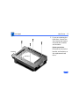
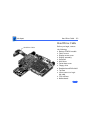
1
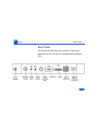
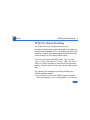
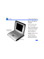
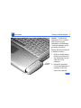
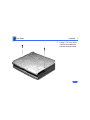
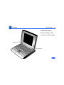
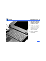
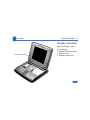
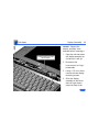
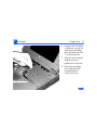
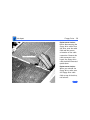
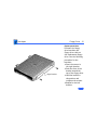
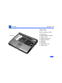
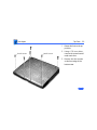
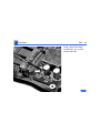
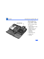
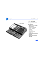
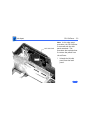
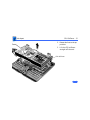
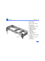
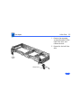
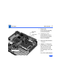
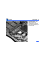
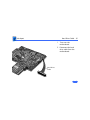
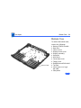
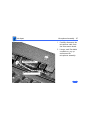
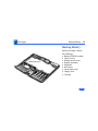
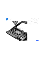
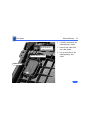
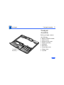
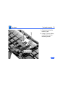
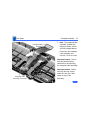
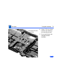
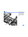
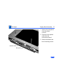
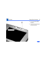
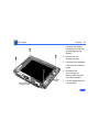
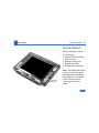
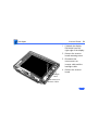
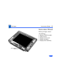
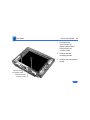
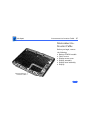
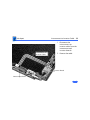
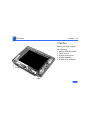
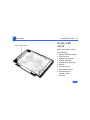
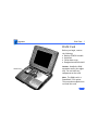
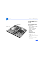
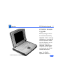
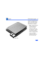
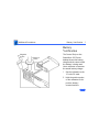
K Service Source
Macintosh PowerBook 550c
This product is forJapan only.
K Service Source
Basics
Macintosh PowerBook 550c
Basics
General Information - 1
General Information
The Macintosh PowerBook 550c features a built-in
trackpad, intelligent batteries, two battery bays, an
optional PCMCIA expansion module, a darker shade of
plastics, and a 10.4" display. The computer is available in
Japan only.
Basics
Rear Panel - 2
Rear Panel
The illustration below shows the location of ports and
connectors on the rear panel of the Macintosh PowerBook
550c.
Basics
PowerBook Screw Matrix - 3
PowerBook Screw Matrix
Nine different types of screws are used in the Macintosh
PowerBook 550c. All are Torx screws and require either a
T-8 or T-6 Torx screwdriver.
Note: The legend for the screws follows on the next page.
Basics
PowerBook Screw Matrix - 4
Legend for Macintosh PowerBook 550c Screws
1
Feet
3
Display bezel, display, clutch, DAA
2
4
5
6
7
8
9
Hard drive, keyboard, bottom case (middle front),
display assembly, floppy drive, daughterboard EMI
shield (top edge), inside edge of top case, right side panel
Trackpad cable and actuator, daughterboard EMI shield
(sides), motherboard standoff
Rear panel
Hard drive bracket
Inverter board, interconnect board
Bottom case (front corners), left side panel
Floppy drive bracket
Basics
PowerBook Cable Matrix - 5
PowerBook Cable Matrix
For a matrix of cables that work with specific models of the
PowerBook family of computers, refer to the PowerBook
Cable Matrix. (The Macintosh PowerBook 550c uses the
same cables as the Macintosh PowerBook 520/540 Series.)
Basics
PCMCIA Module Handling - 6
PCMCIA Module Handling
The PCMCIA (Personal Computer Memory Card
International Association) expansion module is an option for
the Macintosh PowerBook 550c. The module inserts into the
computer’s second (left) battery bay and has two slots that
accept a variety of third-party PCMCIA cards.
There are three types of PCMCIA cards: Type I (3 mm),
Type II (5 mm), and Type III (10 mm). Type I and Type II
cards fit in either the upper or lower slot of the expansion
module. Type III cards fit in the lower slot and take up both
slots.
The following are guidelines for properly handling the
PCMCIA expansion module:
• Do not insert or remove the PCMCIA expansion module
while the computer is on or in Sleep mode. if you do, the
Basics
PCMCIA Module Handling - 7
•
•
•
•
•
•
computer will shut down and all RAM contents will be
lost.
Eject the PCMCIA module using the lever at the front of
the module; eject a PCMCIA card using the PCMCIA Eject
control panel or the PCMCIA Quick Eject module in the
computer’s Control Strip.
Keep the protective cap that comes with the module and
place it back on the module when it is not in use.
Do not open the module or insert anything other than a
PCMCIA card into the card slots.
Keep the module in a safe place, away from small objects
that might fall into it.
Before ejecting a PCMCIA card, make sure nothing is
blocking the card’s slot. To immediately reinsert the
card, pull it out an inch more and then push it back in.
Use only cards that are compatible with the PCMCIA
expansion module. Refer to the compatibility
information that came with the card.
Basics
Battery Information - 8
Battery Information
The Macintosh PowerBook 550c includes two nickelmetal-hydride (NiMH) batteries. Each battery provides
power for up to 3.5 hours of work time, depending on the
battery conservation features employed. A smart processor
included in each battery pack indicates the battery’s charge
status.
For instructions on how to verify the battery voltage, see
the Additional Procedures chapter of this manual.
For additional information on PowerBook batteries,
voltages, ampere hours, and part numbers, see the
PowerBook Battery Matrix in Hardware/Compatibility
Charts.
Basics
Battery Information - 9
Battery Handling
NiMH batteries contain toxic materials. Send
undamaged, dead batteries to Apple for recycling—do not
discard dead batteries with other waste. If the battery is
damaged, do not return it to Apple. Dispose of damaged
batteries according to local ordinances. Review batteryhandling and disposal instructions in Bulletins/Safety.
±Warning:
The following are guidelines for properly handling the
Macintosh PowerBook 550c battery:
• Handle the battery carefully. Do not drop, puncture,
disassemble, mutilate, or incinerate it.
• Do not short-circuit the battery terminals.
• Do not leave a battery in the computer for longer than a
week without plugging in the power adapter.
• Do not leave the battery in hot locations (such as the
trunk of a car).
Basics
Battery Information - 10
• Keep the battery in a cool, dark place; do not store it for
longer than 6 months without recharging.
• If you are using one battery: Completely discharge and
then recharge the battery once every 90 days.
• If you are using two batteries: Swap the left and right
batteries every month.
• Fully charge a replacement battery before using it;
Apple ships batteries in a partially charged state.
K Service Source
Specifications
Macintosh PowerBook 550c
Specifications
Processor - 1
Processor
CPU
Addressing
Motorola 68040 microprocessor
66/33 MHz
32-bit internal registers
32-bit address bus
32-bit data bus
Specifications
Memory - 2
Memory
RAM
4 MB RAM installed on the daughterboard
Expandable to 12 MB with 8 MB Apple RAM expansion card
Expandable to 36 MB with third-party RAM expansion card
ROM
2 MB
PRAM
256 bytes of parameter memory
VRAM
512K of static video display memory
Clock/Calendar
CMOS custom chip with long-life lithium battery
Specifications
Disk Storage - 3
Disk Storage
Floppy Drive
15 mm high, internal, 1.4 MB Apple SuperDrive
Hard Drive
2.5 in., 750 MB hard drive
Specifications
I/O Interfaces - 4
I/O Interfaces
SCSI
HDI-30 SCSI port with 1.5 MB/sec. transfer rate
Supports up to six external SCSI devices
Connect SCSI device to computer with HDI-30 SCSI system cable.
Apple Desktop Bus
Apple Desktop Bus (ADB) port
200 mA maximum current draw for all ADB devices
Serial
RS-422 serial port; mini DIN-8 connector
Sound
Stereo sound-in port
Stereo sound-out headphone jack; standard 3.5 mm stereo
miniplugs
Specifications
I/O Interfaces - 5
Video
Micro DV-14 video-out port; 8 bit, 256 color video output
Supports most Macintosh, VGA, and SVGA monitors
Ethernet
High-speed Ethernet port; Apple AUI connector
Processor-Direct Slot
90-pin processor-direct slot (PDS) for PDS devices or optional
Personal Computer Memory Card International Association
(PCMCIA) adapter/PCMCIA expansion module (allows use of
two Type II or one Type III PCMCIA-type card)
Power Adapter
Power adapter port
Modem
Slot for optional internal modem
Security
Slot for third-party security equipment
Specifications
I/O Devices - 6
I/O Devices
Keyboard
Built-in keyboard with 12 function keys
76 keys domestic, 77 keys ISO
Two-level tilt adjustment
Trackpad
Solid-state trackpad
Microphone
Electret, omnidirectional
Output voltage of 4 mV, peak to peak
Specifications
Sound and Video - 7
Sound and Video
Sound Generator
Video Display
Apple sound chip provides 16-bit sound capable of driving stereo
headphones or other stereo equipment through the sound jack
Built-in stereo speakers
10.4-in. diagonal screen
Backlit, active-matrix color display; 640 x 400 pixels at
thousands of colors; 640 x 480 pixels at 256 colors
Specifications
Electrical - 8
Electrical
Main Battery
Power Adapter
Two nickel-metal-hydride (NiMH) batteries
Up to 3.5 hours of usage per battery before recharging
Recharge time: 2 hours in shut down or sleep mode, 4 hours while
computer is running
110–240 VAC line voltage
40 W, 50–60 Hz
Specifications
Physical - 9
Physical
Dimensions
Height
Width
Depth
Weight
2.25 in. (5.7 cm)
11.5 in. (29.2 cm)
9.65 in. (24.5 cm)
7.3 lb. (3.3 kg)
Specifications
Environmental - 10
Environmental
Operating
Temperature
Storage
Temperature
50–104°F (10–40°C)
-13 to 140°F (-25 to 60°C)
Relative Humidity
20–80% noncondensing
Operating Altitude
0–10,000 ft. (0–3048 m)
Storage Altitude
0–15,000 ft. (0–4572 m)
Specifications
Other - 11
Other
Internal Modem
Sends and receives data at 19.2 bps; sends and receives faxes at
14.4 bps
SCSI Adapter
Enables connection between PowerBook computer and desktop
Macintosh (PowerBook appears as a hard drive on the desktop)
PCMCIA Module
Enables use of two Type I or II PCMCIA cards or one Type III card
K Service Source
Troubleshooting
Macintosh PowerBook 550c
Troubleshooting
General - 1
General
The Symptom Charts included in this chapter will help you
diagnose specific symptoms related to your product. Because cures
are listed on the charts in the order of most likely solution, try
the first cure first. Verify whether or not the product continues to
exhibit the symptom. If the symptom persists, try the next cure.
(Note: If you have replaced a module, reinstall the original module
before you proceed to the next cure.)
If you are not sure what the problem is, or if the Symptom Charts
do not resolve the problem, refer to the Flowchart for the product
family.
For additional assistance, contact Apple Technical Support.
Troubleshooting
Power Manager Reset - 2
Power Manager Reset
Reset the power manager if
• The battery and power adapter are proven good, but the
computer will not power on.
• The computer will not reset after a system crash.
To reset the power manager in the Macintosh PowerBook 550c,
• Remove the AC adapter and the battery.
• Let the unit sit without power hooked up for 3–5 minutes.
• Simultaneously hold down the Control, Command, Option, and
Power On keys for 5–10 seconds.
• Reinstall the battery and, if necessary, reconnect the AC
adapter.
• Turn on the computer.
Troubleshooting
AC Adapter Voltage Test - 3
AC Adapter Voltage Test
To test the AC adapter voltage,
• Use narrow test probes for the leads on your voltmeter
• Make all measurements with the negative or common lead
touching the outer shield of the connector (ground)
• Use the following table to identify the connector pin number,
signal name, and DC voltage present
Connector Pin
Signal
2
VMAIN
1
3
4
DC Voltage
VBATT
16.4–16.6V
GND
0V
GND Sense
16.4–16.6V
0V
Troubleshooting
Symptom Charts/Startup - 4
Symptom Charts
Startup
RAM failure occurs
(eight-tone error
chord sounds after
startup chord)
1
2
3
4
Reseat RAM expansion card and check connection.
Replace RAM expansion card.
Replace daughterboard.
Replace motherboard.
Hardware failure
occurs (four-tone
error chord sounds
after startup chord)
1
Disconnect hard drive cable and restart computer. If startup
sequence is normal, reconnect cable and retest.
Replace hard drive.
Disconnect floppy drive cable and restart computer. If
startup sequence is normal, reconnect cable and retest.
Replace floppy drive.
Replace motherboard.
2
3
4
5
Troubleshooting
Symptom Charts/Power - 5
Power
Screen is blank;
computer doesn’t
respond
1
2
3
4
5
6
7
8
9
Restart computer.
Connect power adapter and restart computer in 3–4 minutes.
Try known-good, charged main battery.
Check all interconnect board, daughterboard, and
motherboard connections.
Reset the power manager.
Replace keyboard.
Replace interconnect board.
Replace daughterboard.
Replace motherboard.
Troubleshooting
Symptom Charts/Power (Continued) - 6
Power (Continued)
After you remove
main battery, some
Control Panel
settings are different
1
2
3
4
5
Check cables.
Replace backup battery.
Replace interconnect board.
Replace daughterboard.
Replace motherboard.
Power adapter is
plugged in, but
Control Strip doesn’t
indicate adapter is
connected
1
2
3
4
Verify that power adapter is connected correctly.
Try known-good, charged main battery.
Try known-good power adapter.
Replace motherboard.
Troubleshooting
Symptom Charts/Power (Continued) - 7
Power (Continued)
Low-power warning
appears
1
2
3
4
5
6
Computer runs when
plugged into wall
outlet but not on
battery power;
battery voltage is
within tolerance
1
2
3
Recharge battery or attach power adapter.
Verify that peripherals are low-power.
Reduce use of floppy or hard drive, modem, sound, backlight,
or other power-consuming devices, or connect power
adapter.
Try known-good, charged main battery.
Try known-good power adapter.
Replace motherboard.
Reseat battery to make sure battery is mating with contacts
on motherboard.
Replace motherboard.
Return computer to Apple.
Troubleshooting
Symptom Charts/Power (Continued) - 8
Power (Continued)
Computer won’t
power up
1
2
3
4
5
6
7
Restart computer.
Connect power adapter and restart computer in 3–4 minutes.
Try known-good power adapter. Verify power adapter tip is
not chipped or cracked.
Try known-good, charged main battery.
Replace fuse on motherboard.
Replace motherboard.
Return computer to Apple.
Troubleshooting
Symptom Charts/Video - 9
Video
Pixel never comes on
or is always on
If more than five pixels do not come on or are always on, replace
display.
Partial or full row of
pixels is always on or
never comes on
1
2
3
4
Check cables.
Replace interconnect board.
Replace motherboard.
Replace display.
Troubleshooting
Symptom Charts/Video (Continued) - 10
Video (Continued)
Display is very light
or totally white
1
2
3
4
5
6
7
8
Display stopped
working or dimmed
but is fine now
Adjust screen contrast and brightness settings.
Verify cable, inverter board, interconnect board,
daughterboard, and motherboard connections.
Replace inverter board.
Replace interconnect board.
Replace interconnect-to-display cable.
Replace display.
Replace daughterboard.
Replace motherboard.
Let screen warm up for 30 minutes.
Troubleshooting
Symptom Charts/Video (Continued) - 11
Video (Continued)
Backlight doesn’t
operate
1
2
Verify that backlight cable connection is secure.
Check cable, inverter board, interconnect board,
daughterboard, and motherboard connections.
3 Verify that cables are not pinched or severed.
4 Replace inverter board.
5 Replace interconnect-to-inverter cable.
6 Replace interconnect board.
7 Replace interconnect-to-display cable.
8 Replace display.
9 Replace daughterboard.
10 Replace motherboard.
Troubleshooting
Symptom Charts/Video (Continued) - 12
Video (Continued)
No display, but
computer appears to
operate correctly
1
2
3
Press any key to wake computer from system sleep.
Adjust screen contrast and brightness settings.
Verify cable, inverter board, trackpad, keyboard, interconnect board, daughterboard, and motherboard connections.
4 Connect power adapter.
5 Replace inverter board.
6 Replace interconnect board.
7 Replace interconnect-to-display cable.
8 Replace display.
9 Reseat daughterboard.
10 Replace daughterboard.
11 Replace motherboard.
Troubleshooting
Symptom Charts/Floppy Drive - 13
Floppy Drive
Audio and video
present, but internal
floppy drive does not
operate
1
2
3
4
5
Try known-good floppy disk.
Check floppy drive cable connection.
Replace floppy drive cable.
Replace floppy drive.
Replace motherboard.
Disk ejects while
booting; display
shows Mac icon with
blinking X
1
2
3
4
5
6
7
Try known-good system disk.
Verify that trackpad and trackpad button are working.
Verify that keyboard is working.
Check floppy drive cable connection.
Replace floppy drive cable.
Replace floppy drive.
Replace motherboard.
Troubleshooting
Symptom Charts/Floppy Drive (Continued) - 14
Floppy Drive (Continued)
Disk does not eject
1
2
3
4
5
6
7
8
Switch off system and hold trackpad button down while you
switch system on.
Eject disk manually by carefully inserting opened paper clip
into hole near floppy drive slot.
If PowerBook serial number is between FC410 and FC414 or
between CD412 and CK414, replace floppy drive.
Check floppy drive cable connection.
Reinstall floppy drive brackets. (Refer to “Floppy Drive” in
Take Apart.)
Replace floppy drive cable.
Replace floppy drive.
Replace motherboard.
Troubleshooting
Symptom Charts/Floppy Drive (Continued) - 15
Floppy Drive (Continued)
Disk initialization
fails
1
2
3
4
Try known-good floppy disk.
Check floppy drive cable connection.
Replace floppy drive cable.
Replace floppy drive.
Read/write/copy
error
1
2
3
4
5
Try known-good floppy disk.
Check floppy drive cable connection.
Try application disk and data file on floppy disk.
Replace floppy drive cable.
Replace floppy drive.
Troubleshooting
Symptom Charts/Hard Drive - 16
Hard Drive
Internal hard drive
does not operate
1
2
3
4
5
6
7
Make sure power adapter is connected.
Disconnect external SCSI devices.
Check hard drive cable connection.
Use HD SC Setup to reinitialize drive.
Replace hard drive cable.
Replace hard drive.
Replace motherboard.
Troubleshooting
Symptom Charts/Peripheral - 17
Peripheral
After you connect
external SCSI device,
computer does not
boot
1
2
3
4
5
6
7
Switch on external SCSI device before starting computer.
Check cable connections.
Verify that SCSI chain is terminated correctly.
Verify that SCSI select switch setting on external device is
unique.
Verify operation of internal hard drive.
Try known-good external SCSI device.
Replace motherboard.
Troubleshooting
Symptom Charts/Peripheral (Continued) - 18
Peripheral (Continued)
Cursor does not move
when you are using
trackpad
1
2
3
4
5
6
Reset the power manager.
Check trackpad connections.
Check interconnect board, keyboard, and motherboard
connections.
Connect low-power mouse and try to move cursor. If cursor
moves, try using trackpad and keyboard. If trackpad does not
move cursor, replace trackpad. If keyboard does not move
cursor, replace keyboard.
Replace interconnect board.
Replace motherboard.
Troubleshooting
Symptom Charts/Peripheral (Continued) - 19
Peripheral (Continued)
Cursor intermittently
does not move or
moves erratically
1
2
3
4
5
6
7
Reset the power manager.
Clean trackpad surface.
Check trackpad connections.
Replace trackpad.
Replace keyboard.
Replace interconnect board.
Replace motherboard.
Cursor does not move
when you are using
mouse
1
2
3
4
5
Check mouse connection to ADB port.
Reset the power manager.
Clean mouse ball and inside mouse.
Replace mouse.
Replace motherboard.
Troubleshooting
Symptom Charts/Peripheral (Continued) - 20
Peripheral (Continued)
Cursor moves, but
clicking trackpad
button has no effect
No response to any
key on keyboard
1
2
3
4
5
6
7
Reset the power manager.
Check trackpad connections.
Check interconnect board, keyboard, and motherboard
connections.
Replace trackpad.
Replace keyboard.
Replace interconnect board.
Replace motherboard.
1
2
3
4
5
6
Verify that computer is on.
Reset the power manager.
Check keyboard and interconnect board connections.
Replace keyboard.
Replace interconnect board.
Replace motherboard.
Troubleshooting
Symptom Charts/Peripheral (Continued) - 21
Peripheral (Continued)
Known-good directconnect printer does
not print
1
2
3
4
5
6
7
Verify that System is 7.1.1 or later.
Verify that Chooser and Control Panel settings are correct.
Check cables.
Replace printer cable.
Try known-good printer.
Replace daughterboard.
Replace motherboard.
Troubleshooting
Symptom Charts/Peripheral (Continued) - 22
Peripheral (Continued)
Known-good network
printer does not print
1
2
3
4
5
6
7
In disk mode,
computer does not
display SCSI icon
until host is booted,
or computer crashes
when host is shut
down
Verify that System is 7.1.1 or later.
Verify that Chooser and Control Panel settings are correct.
Check cables.
Replace printer cable.
Try known-good printer. If printer works, troubleshoot
network.
Replace daughterboard.
Replace motherboard.
Replace motherboard.
Troubleshooting
Symptom Charts/Peripheral (Continued) - 23
Peripheral (Continued)
Device connected to
external modem port
doesn’t work
1
2
3
4
5
6
Verify that External Modem is selected in CDEV.
Verify that System is 7.1.1 or later.
Check cables.
Test device with known-good computer.
Replace daughterboard.
Replace motherboard.
I/O devices are
unrecognized or
garbage is
transmitted or
received
1
2
3
4
Verify that System is 7.1.1 or later.
Check cables.
Verify that SCSI device is correctly terminated.
Verify that SCSI select switch setting on external device is
unique.
Test device with known-good computer.
Replace daughterboard.
Replace motherboard.
5
6
7
Troubleshooting
Symptom Charts/Internal Modem - 24
Internal Modem
Internal modem
options do not appear
in CDEV
1
2
3
4
Verify that System is 7.1.1 or later.
Reseat modem card.
Replace modem card.
Replace motherboard.
Modem does not
respond properly to
AT command set
instructions
1
Verify that baud rate and data format settings of
communications application are compatible with internal
modem and remote modem.
Check phone cord connection and operation.
Verify that System is 7.1.1 or later.
Reseat modem card.
Replace modem card.
2
3
4
5
Troubleshooting
Symptom Charts/Internal Modem (Continued) - 25
Internal Modem (Continued)
Strange mix of
characters appears
on screen
1
2
3
4
5
6
7
Verify that baud rate and data format settings of
communications application are compatible with internal
modem and remote modem.
Check phone cord connection and operation.
Verify that System is 7.1.1 or later.
Reseat modem card.
Replace modem card.
Replace daughterboard.
Replace motherboard.
Modem interferes
with system sound
1
2
3
4
Reseat modem card.
Replace modem card.
Replace interconnect board.
Replace motherboard.
Troubleshooting
Symptom Charts/Internal Modem (Continued) - 26
Internal Modem (Continued)
Modem does not
respond to incoming
call
1
2
3
4
If computer is in sleep mode, verify that Wake On Ring
option in CDEV is selected.
Check phone cord connection and operation.
Replace modem card.
Replace motherboard.
Modem has no sound
output
1
2
3
4
Verify that Control Panel volume setting is above 0.
Replace modem card.
Replace interconnect board.
Replace motherboard.
Troubleshooting
Symptom Charts/Internal Modem (Continued) - 27
Internal Modem (Continued)
Modem connects but
does not communicate
with remote modem
1
2
Verify that remote modem needs error correction (error
correction is internal modem default).
If remote modem does not need error correction, type AT
&Q0 to disable error correction.
Troubleshooting
Symptom Charts/Internal Modem (Continued) - 28
Internal Modem (Continued)
You are using System
7.5 and two messages
appear: “This
Macintosh may not
have been shut down
properly” and
“Incoming fax cannot
be received because
internal modem could
not be identified...”
Following the
messages, the system
“hangs.”
1
2
Restart while holding down the Space bar. (This procedure
will open Extensions Manager.)
• Disable the PowerPort 500 control panel by removing the
check mark.
• Close the Extensions Manager window to complete startup.
• Open the General Controls control panel and turn off the
shutdown warning.
• Open the Extensions Manager control panel and turn on the
PowerPort 500 control panel.
• Restart.
Restart with extensions off and remove the GlobalFax files,
GlobalFax Personal folders, and PowerPort 500 from the
System folder.
• Reinstall the Global Village software.
• Move the GlobalFax addresses into a new folder.
Troubleshooting
Symptom Charts/PCMCIA Module - 29
PCMCIA Module
PCMCIA card won’t
eject
1
2
Make sure PCMCIA slot is not blocked.
Insert straightened paper clip into hole next to slot.
PCMCIA card is
inserted but doesn’t
appear on desktop
If “defective card” or “unrecognizable card” appears in place of
card name in PCMCIA Eject control panel, card is damaged or
computer does not have software required to support it. Eject
card.
Troubleshooting
Symptom Charts/Miscellaneous - 30
Miscellaneous
Screen goes blank and
computer shuts down
every few minutes
Computer is going into system sleep to conserve battery power.
Adjust sleep delays in Control Panel or connect power adapter.
Application seems to
run slower after a few
seconds
Computer is switching to system rest. If system rest is
interfering with operation of application, connect power adapter.
Hard drive is slow to
respond, or screen
goes blank too often
Adjust sleep delays in Control Panel or connect power adapter.
Troubleshooting
Symptom Charts/Miscellaneous (Continued) - 31
Miscellaneous (Continued)
No sound from
speaker
1
2
3
4
5
PowerBook clicks
when closed
Verify that volume setting in Control Panel is above 0.
Verify that no external speaker is plugged in.
Check connections of speaker to interconnect board and
interconnect board to motherboard.
Replace interconnect board.
Replace motherboard.
Reinstall center base cover, making sure screw nearest SCSI port
is installed first. (See Take Apart.)
K Service Source
Take Apart
Macintosh PowerBook 550c
Take Apart
Battery/PCMCIA Module - 1
Battery/PCMCIA
Module
Before you begin, disconnect the power adapter.
Note: This procedure covers
removal of the main battery,
second battery or PCMCIA
expansion module, and
battery contact cover.
Second Battery/
PCMCIA Module
Important: Before removing
the battery, use the
Macintosh Shut Down
command. Otherwise, all
RAM contents will be lost.
Main Battery
Take Apart
Battery/PCMCIA Module - 2
Caution: The Macintosh
PowerBook 550c contains
devices that are very
susceptible to ESD damage.
To prevent damage, wear a
grounding wriststrap.
Review the ESD precautions
in Bulletins/Safety.
1
Release
Button
2
Slide the release button
toward you and pull out
the main battery on the
right side of the
computer.
Repeat the procedure
for the second battery, if
installed, on the left
side of the computer.
Take Apart
Battery/PCMCIA Module - 3
3
Battery
Bezel
Note: The battery bezel
includes a separate latch
and latch spring.
Remove the bezel
carefully so these parts
do not fall out.
If you are replacing the
battery bezel, pry up
both ends of the bezel and
lift it off the main
battery.
Latch/
Spring
Replacement Note: Make
sure the battery bezel
latch spring is compressed against the end
of the battery before
replacing the bezel.
Take Apart
Battery/PCMCIA Module - 4
4
Battery Contact Cover
If you are replacing the
battery contact cover,
press in on the sides of
the cover and slide it off
the main battery.
Take Apart
Battery/PCMCIA Module - 5
5
6
Lever
Note: Complete the
following step if a
PCMCIA expansion
module is installed in the
computer.
Using the tip of your
finger, rotate the lever
at the front of the
PCMCIA module toward
you.
Note: You may have to
use some force when
pulling the module out
of the computer.
Holding onto the lever,
pull the PCMCIA module
out of the computer.
Take Apart
Keyboard - 6
Keyboard
Before you begin, remove
the battery/PCMCIA module.
Keyboard
Take Apart
Keyboard - 7
1
Using a T-8 torx driver,
remove the middle two
bottom housing screws.
Take Apart
Keyboard - 8
2
3
Keyboard
Using a small flat-blade
screwdriver, lift the
front of the keyboard and
pull it forward slightly.
Rotate the keyboard so
that it is perpendicular
to the top cover.
Take Apart
Keyboard - 9
4
Locking
Tabs
5
Release the locking tabs
on the two keyboard
cable connectors and
disconnect the cables
from the motherboard.
Lift off the keyboard.
Take Apart
Hard Drive - 10
Hard Drive
Before you begin, remove
the following:
• Battery/PCMCIA module
• Keyboard
Hard Drive
Take Apart
Hard Drive - 11
1
Using a T-8 torx driver,
remove the hard drive
mounting screw.
Take Apart
Hard Drive - 12
2
Hard Drive
3
Hard
Drive
Cable
4
Using a small flat-blade
screwdriver, pry up the
front of the hard drive
and slide it forward 1/2
inch.
Note: Use a rocking
motion to disconnect the
hard drive cable from
the hard drive.
Lift the drive partway
out of the unit and
disconnect the hard drive
cable.
Remove the hard drive.
Take Apart
Hard Drive - 13
5
Bracket
Insulator
If you are replacing the
hard drive, remove the
four screws and remove
the hard drive bracket
and insulator.
Replacement Note:
Reinstall the hard drive
bracket and insulator on
the replacement hard
drive.
Take Apart
Clutch Covers - 14
Clutch Covers
Before you begin, remove
the battery/PCMCIA module.
Clutch Cover
Clutch Cover
Take Apart
Clutch Covers - 15
1
2
3
Latch
4
Open the unit and rotate
the display assembly as
far back as it will go.
Using a flat-blade
screwdriver and your
fingers, press in on
both sides of the wide end
of the right clutch cover
and release the two
front latches.
Rotate the clutch cover
up, release the third
latch, and remove the
cover.
Repeat for the left clutch
cover.
Take Apart
Clutch Covers - 16
Replacement Caution: Be
careful not to pinch or rip
the display cable when you
replace the right clutch
cover.
Take Apart
Display Access Cover - 17
Display Access
Cover
Before you begin, remove
the battery/PCMCIA module.
Display Access
Cover
Take Apart
Display Access Cover - 18
1
2
3
Open the unit and rotate
the display assembly as
far back as it will go.
Using a small flat-blade
screwdriver, pry up the
display access cover at
the three slots in the
front of the cover.
Remove the display
access cover.
Take Apart
Display Assembly - 19
Display Assembly
Display Assembly
Before you begin, remove
the following:
• Battery/PCMCIA module
• Clutch covers
• Display access cover
Take Apart
Display Assembly - 20
Caution: Support the
display assembly from
beneath before removing it.
Interconnect-to-Logic
Board Cable
1
2
3
4
Open the unit and rotate
the display assembly as
far back as it will go.
Disconnect the
interconnect-to-logicboard cable.
Using a T-8 torx driver,
remove the two display
mounting screws.
Slide the display
assembly to the left so
that the right clutch
clears the loop of the
Take Apart
Display Assembly - 21
5
interconnect-to-logicboard cable.
Remove the display
assembly.
Take Apart
Center Base Cover - 22
Center Base Cover
Before you begin, remove
the following:
• Battery/PCMCIA module
• Keyboard
Center Base Cover
Take Apart
Center Base Cover - 23
1
Using a T-8 torx driver,
remove the two rear
panel screws.
Replacement Caution:
When replacing the rear
panel screws, be sure to
install the right screw
first (the screw nearest
the SCSI port).
Take Apart
Center Base Cover - 24
2
Screw Carrier
3
Pull the center base
cover forward slightly
and slide it 1/2 inch to
the right to release the
two screw carriers.
Remove the center base
cover.
Take Apart
Floppy Drive - 25
Floppy Drive
Before you begin, remove
the following:
• Battery/PCMCIA module
• Keyboard
• Center base cover
Floppy Drive
Take Apart
Floppy Drive - 26
1
Using a T-8 torx driver,
remove the two floppy
drive screws.
Take Apart
Floppy Drive - 27
2
3
4
Floppy Drive Cable
Using a small flat-blade
screwdriver, pry up the
cable end of the floppy
drive and slide the drive
1/2 inch to the left.
Slide the drive forward
slightly and lift it
partway out of the unit.
Disconnect the floppy
drive cable from the
motherboard and
remove the drive.
Take Apart
Floppy Drive Cable
Floppy Drive - 28
Replacement Caution:
Before disconnecting the
floppy drive cable from
the drive, note the cable
folds and the correct
orientation of the cable
connection. Because the
cable connector is not
keyed, the floppy drive
cable could be reinserted
upside down.
Replacement Caution:
When you reinstall the
floppy drive, make sure
the floppy drive cable
folds on top of the drive,
not below it.
Take Apart
Floppy Drive - 29
5
If you are replacing the
floppy drive or floppy
drive cable, release the
locking tabs and
disconnect the cable
from the drive.
Locking Tab
Floppy Drive Cable
Take Apart
Floppy Drive - 30
6
7
If you are replacing the
floppy drive, remove the
two right bracket screws
and remove the right
bracket.
Remove the two left
bracket screws and
remove the left bracket.
Take Apart
Floppy Drive - 31
Right Bracket
Replacement Note:
Reinstall the floppy
drive brackets and
floppy drive cable on
the replacement floppy
drive. Use the following
procedure for the
brackets:
• Start the screws in
the right bracket.
• Push the front of the
bracket toward the
top of the floppy drive.
• Hold the bracket in
this position and
retighten the screws.
• Repeat for the left
bracket.
Take Apart
Floppy Drive - 32
Replacement Caution:
If the brackets are not
pushed toward the top of
the floppy drive, the
floppy disk may not eject
properly.
Take Apart
Daughterboard EMI Shield - 33
Daughterboard
EMI Shield
Before you begin, remove
the following:
• Battery/PCMCIA module
• Keyboard
• Center base cover
Daughterboard
EMI Shield
Take Apart
Daughterboard EMI Shield - 34
1
2
Remove the three
mounting screws.
Using a small flat-blade
screwdriver, pry up
and remove the
daughterboard EMI
shield.
Replacement Caution: Make
sure all the tabs on the sides
of the shield fit inside the
daughterboard guide.
Daughterboard
EMI Shield
Take Apart
Daughterboard - 35
Daughterboard
Daughterboard
Before you begin, remove
the following:
• Battery/PCMCIA module
• Keyboard
• Center base cover
• Daughterboard EMI shield
• RAM card (if installed)
• Modem card (if installed)
Take Apart
Daughterboard - 36
Note: To remove the
daughterboard, you will need
to adapt an IC extractor so
that it has a wide grip.
1
Grasp an IC extractor by
the legs and pull
outward.
Take Apart
Daughterboard - 37
2
3
Daughterboard
RAM Expansion Connector
Daughterboard Connector
Notch
Remove the plastic
retainer bar.
Note: The daughterboard
is connected to the
motherboard below the
RAM card connector.
Caution: You may have
to use some force to
disconnect the daughterboard. Use an IC
extractor, as illustrated.
Do not pry up the board
with a screwdriver.
Place the legs of the IC
extractor in the notches
at the end of the daughterboard and pull up.
Take Apart
Top Case - 38
Top Case
Top Case
Before you begin, remove
the following:
• Battery/PCMCIA module
• Clutch covers
• Display access cover
• Display assembly
• Keyboard
• Hard drive
• Center base cover
• Floppy drive
Take Apart
Top Case - 39
1
Small Screw
Small Screw
2
3
Rotate the feet to the up
position.
Using a T-8 torx driver,
remove the screw located
under each foot.
Remove the four screws
at the front edge of the
bottom case.
Take Apart
Top Case - 40
4
Remove the remaining
screw on the inside top
edge of the case.
Take Apart
Top Case - 41
5
Trackpad Cable
Caution: The top case is
connected to the
motherboard by the
trackpad cable. Be
careful not to lift the top
case too far off the unit
or you may damage the
cable.
Carefully lift and rotate
the top case toward you
and disconnect the
trackpad cable from the
motherboard.
Trackpad Cable Connector
Take Apart
Top Case - 42
6
Interconnect-to-Logic
Board Cable
Right Clutch
Opening
EMI Clip
7
Remove the
interconnect-to-logic
board cable from the
opening for the right
clutch.
Remove the top case.
Replacement Note: Before
securing the top case to the
bottom case, thread the
interconnect-to-logic
board cable through the
opening for the right
clutch. Form a loop around
the EMI clip by wrapping
the cable from behind and
then over and under the clip.
Take Apart
Fuse - 43
Fuse
Before you begin, remove
the following:
• Battery/PCMCIA module
• Clutch covers
• Display access cover
• Display assembly
• Keyboard
• Hard drive
• Center base cover
• Floppy drive
• Top case
Fuse
Take Apart
Fuse - 44
Using a small flat-blade
screwdriver, pry up and
remove the fuse.
Fuse
Take Apart
Interconnect-to-Logic-Bd. Cable - 45
Interconnect-toLogic-Board Cable
Interconnect-toLogic-Bd. Cable
Before you begin, remove
the following:
• Battery/PCMCIA module
• Clutch covers
• Display access cover
• Display assembly
• Keyboard
• Hard drive
• Center base cover
• Floppy drive
• Top case
Take Apart
Interconnect-to-Logic-Bd. Cable - 46
Interconnectto-Logic-Board
Cable
Caution: Before disconnecting the interconnectto-logic-board cable, note
the correct orientation of
the cable connection.
Because the connector is not
keyed, the cable could be
reinserted upside down.
Disconnect the
interconnect-to-logicboard cable from the
motherboard and remove
the cable.
Take Apart
Side Panels - 47
Side Panels
Left Side
Panel
Right Side
Panel
Before you begin, remove
the following:
• Battery/PCMCIA module
• Clutch covers
• Display access cover
• Display assembly
• Keyboard
• Hard drive
• Center base cover
• Floppy drive
• Top case
Take Apart
Side Panels - 48
1
2
3
4
Using a T-8 torx driver,
remove the right sidepanel mounting screw.
Lift the panel slightly,
slide it back, and remove
it from the CPU
stiffener.
Using a T-8 torx driver,
remove the three left
side-panel mounting
screws.
Slide the panel to the left
and remove it from the
CPU stiffener.
Take Apart
CPU Stiffener - 49
CPU Stiffener
CPU Stiffener
Before you begin, remove
the following:
• Battery/PCMCIA module
• Clutch covers
• Display access cover
• Display assembly
• Keyboard
• Hard drive
• Center base cover
• Floppy drive
• Daughterboard EMI shield
• Top case
• Interconnect-to-logicbd. cable
Take Apart
CPU Stiffener - 50
Left Side Panel
Latch
Note: In this take-apart
procedure, the CPU stiffener
is removed with the side
panels attached. This
procedure also explains how
to remove the panels from
the stiffener.
1
Unlatch the left side
panel from the back
panel.
Take Apart
CPU Stiffener - 51
2
3
Rotate the feet to the up
position.
Lift the CPU stiffener
straight off the unit.
CPU Stiffener
Take Apart
CPU Stiffener - 52
Note: If you are replacing
the CPU stiffener, remove
the side panels.
4
5
6
7
Using a T-8 torx driver,
remove the right sidepanel screw.
Lift the panel slightly,
slide it back, and remove
it from the CPU
stiffener.
Using a T-8 torx driver,
remove the three left
side-panel screws.
Slide the panel to the left
and remove it from the
CPU stiffener.
Take Apart
EMI Clip
Clutch Peg
CPU Stiffener - 53
Replacement Caution: Make
sure both EMI clips fold on
top of the clutch pegs. If the
right clip accidentally folds
backward and touches the
pins for the power
connector, the contact could
short out the motherboard.
Take Apart
Lifter Feet - 54
Lifter Feet
Lifter
Foot
Lifter Foot
Before you begin, remove
the following:
• Battery/PCMCIA module
• Clutch covers
• Display access cover
• Display assembly
• Keyboard
• Hard drive
• Center base cover
• Floppy drive
• Daughterboard EMI shield
• Top case
• Interconnect-to-logicbd. cable
• CPU stiffener
Take Apart
Lifter Feet - 55
1
2
Lifter
Foot
Lifter Foot
Remove the mounting
screw and washer for the
right lifter foot, and
remove the foot.
Repeat for the left lifter
foot.
Take Apart
Motherboard - 56
Motherboard
Motherboard
Before you begin, remove
the following:
• Battery/PCMCIA module
• Clutch covers
• Display access cover
• Display assembly
• Keyboard
• Hard drive
• Center base cover
• Floppy drive
• Daughterboard EMI shield
• Top case
• Interconnect-to-logicbd. cable
• CPU stiffener
• DAA card (if installed)
Take Apart
Motherboard - 57
1
Sound-In
Port
Sound-Out
Port
2
3
4
Standoff & Peg
Remove the
motherboard mounting
screw and standoff.
Carefully pry the
motherboard from the
positioning peg located
below the standoff.
Slide the board forward
1/4 inch.
Caution: In lifting the
motherboard, be careful
that the sound-in and
sound-out ports clear
the openings in the rear
panel.
Lift off the motherboard.
Take Apart
Motherboard - 58
5
Daughterboard
If you are replacing the
motherboard, disconnect the RAM card (if
installed), daughterboard, and modem card
(if installed).
Take Apart
Motherboard - 59
Replacement Note: Make
sure the front of the
motherboard fits securely
below the positioning peg on
the bottom case.
Positioning Peg
Take Apart
Hard Drive Cable - 60
Hard Drive Cable
Hard Drive Cable
Before you begin, remove
the following:
• Battery/PCMCIA module
• Clutch covers
• Display access cover
• Display assembly
• Keyboard
• Hard drive
• Center base cover
• Floppy drive
• Daughterboard EMI shield
• Top case
• Interconnect-to-logicbd. cable
• CPU stiffener
• Motherboard
Take Apart
Hard Drive Cable - 61
1
2
Hard Drive
Cable
Turn over the
motherboard.
Disconnect the hard
drive cable from the
motherboard.
Take Apart
Rear Door - 62
Rear Door
No preliminary steps are
required.
Rear Door
Take Apart
Rear Door - 63
1
Open the rear door.
3
Unhinge the bottom door
pegs and remove the rear
door.
2
Door Peg
Door Peg
Carefully bend the door
so that the middle bows
downward.
Take Apart
Bottom Case - 64
Bottom Case
Bottom Case
To remove the bottom case,
remove the following:
• Battery/PCMCIA module
• Rear door
• Clutch covers
• Display access cover
• Display assembly
• Keyboard
• Hard drive
• Center base cover
• Floppy drive
• Daughterboard EMI shield
• Top case
• Interconnect-to-logicbd. cable
• Side panels
Take Apart
Bottom Case - 65
• CPU stiffener
• Motherboard
Take Apart
Microphone Assembly - 66
Microphone
Assembly
Before you begin, remove
the following:
• Battery/PCMCIA module
• Display access cover
Microphone
Assembly
Take Apart
Microphone Assembly - 67
1
2
Microphone Cable
Microphone Assembly
Carefully disconnect the
microphone cable from
the interconnect board.
Using a small flat-blade
screwdriver, pry up
and remove the
microphone assembly.
Take Apart
Backup Battery - 68
Backup Battery
Backup Battery
Before you begin, remove
the following:
• Battery/PCMCIA module
• Clutch covers
• Display access cover
• Display assembly
• Keyboard
• Hard drive
• Center base cover
• Floppy drive
• Top case
Take Apart
Backup Battery - 69
1
Backup Battery
Cover
Using a small flat-blade
screwdriver, pry up
and remove the backup
battery cover.
Take Apart
Backup Battery - 70
2
Backup Battery
Cable Connector
3
4
Backup Battery Cable
Cable Guides
Carefully disconnect the
backup battery cable.
Remove the cable from
the cable guides.
Pry up and remove the
backup battery and
cable.
Take Apart
Trackpad Assembly - 71
Trackpad
Assembly
Trackpad
Assembly
Before you begin, remove
the following:
• Battery/PCMCIA module
• Clutch covers
• Display access cover
• Display assembly
• Keyboard
• Hard drive
• Center base cover
• Floppy drive
• Top case
Take Apart
Trackpad Assembly - 72
1
2
Backup Battery
Cable Connector
Disconnect the backup
battery cable.
Using a T-8 torx driver,
remove the front two
mounting screws.
Take Apart
Trackpad Assembly - 73
Trackpad Cable
Assembly
3
Note: The trackpad cable
assembly includes the
display actuator switch
and the trackpad button.
Disconnect the trackpad
cable assembly and
remove it from the unit.
Replacement Note: Reconnect the backup battery
cable before reconnecting
the trackpad cable assembly.
Trackpad Cable
Assembly Connector
Replacement Note: Before
securing the two screws,
make sure the flex cable
routes on top of the
assembly.
Take Apart
Trackpad Assembly - 74
Trackpad Actuator
Assembly
4
5
Using a T-8 torx driver,
remove the remaining
two mounting screws.
Pry up and remove the
trackpad actuator
assembly.
Take Apart
Trackpad Assembly - 75
6
Trackpad Logic
Board
With your fingers, push
up from underneath the
trackpad logic board and
remove it from the top
case.
Take Apart
Display Bezel Assembly - 76
Display Bezel Assembly
Display Bezel
Assembly
Before you begin, remove
the following:
• Battery/PCMCIA module
• Clutch covers
• Display access cover
• Display assembly
Take Apart
Display Bezel Assembly - 77
1
2
3
Speaker Cable
Microphone
Remove the microphone
from the plastic
retainer.
Disconnect the speaker
cable from the
interconnect board.
Remove the bottom two
bezel mounting screws.
Take Apart
Display Bezel Assembly - 78
4
5
Rubber Bumper
Pry off the two rubber
bumpers.
Remove the top two bezel
mounting screws.
Take Apart
Display Bezel Assembly - 79
6
Note: Two hooks on each
side of the bezel secure
it to the rear housing.
Pull the display bezel
forward and lift it off the
rear housing.
Display Bezel
Take Apart
Display - 80
Display
Display
Before you begin, remove
the following:
• Battery/PCMCIA module
• Clutch covers
• Display access cover
• Display assembly
• Display bezel assembly
Note: The display EMI shield
is attached to the display
with adhesive. Pry up the
shield carefully when
removing it from the
display.
Take Apart
Display - 81
1
2
3
4
Interconnect-toDisplay Cable
Backlight
Cable
5
Fold back the display
EMI shield from the top
and side edges of the
display.
Remove the four
mounting screws.
Disconnect the backlight
cable from the inverter
board.
Disconnect the
interconnect-todisplay cable from the
interconnect board.
Lift the display from the
rear housing.
Take Apart
Display - 82
6
Connector
Interconnect-to-Display Cable
If you are replacing the
display, disconnect and
remove the interconnect-to-display
cable from the back of
the display.
Take Apart
Inverter Board - 83
Inverter Board
Before you begin, remove
the following:
• Battery/PCMCIA module
• Clutch covers
• Display access cover
• Display assembly
• Display bezel assembly
Inverter
Board
Note: The display EMI shield
covers the inverter board
and attaches to the display
with adhesive. Pry up the
shield carefully before
removing the inverter
board.
Take Apart
Inverter Board - 84
1
2
3
4
Backlight
Cable
Interconnect-toInverter Cable
Fold back the display
EMI shield from the
right edge of the display.
Remove the inverter
board mounting screw.
Disconnect the
interconnect-toinverter cable and the
backlight cable.
Remove the inverter
board.
Take Apart
Interconnect Board - 85
Interconnect Board
Before you begin, remove
the following:
• Battery/PCMCIA module
• Clutch covers
• Display access cover
• Display assembly
• Display bezel assembly
Interconnect
Board
Take Apart
Interconnect Board - 86
1
2
3
Interconnectto-Display Cable
Interconnect-toInverter Cable
Disconnect the
interconnect-todisplay cable and the
interconnect-toinverter cable.
Remove the two
mounting screws.
Remove the interconnect
board.
Take Apart
Interconnect-to-Inverter Cable - 87
Interconnect-toInverter Cable
Before you begin, remove
the following:
• Battery/PCMCIA module
• Clutch covers
• Display access cover
• Display assembly
• Display bezel assembly
• Display
Interconnect-toInverter Cable
Take Apart
Interconnect-to-Inverter Cable - 88
1
Interconnect-toInverter Cable
2
Disconnect the
interconnect-toinverter cable from the
interconnect and
inverter boards.
Remove the cable.
Inverter Board
Interconnect Board
Take Apart
Interconnect-to-Display Cable - 89
Interconnect-toDisplay Cable
Before you begin, remove
the following:
• Battery/PCMCIA module
• Clutch covers
• Display access cover
• Display assembly
• Display bezel assembly
• Display
Interconnect-to-Display Cable
Take Apart
Interconnect-to-Display Cable - 90
1
2
Connector
Interconnect-to-Display Cable
Disconnect the
interconnect-todisplay cable from the
back of the display.
Remove the cable.
Take Apart
Clutches - 91
Clutches
Before you begin, remove
the following:
• Battery/PCMCIA module
• Clutch covers
• Display access cover
• Display assembly
• Display bezel assembly
Clutch
Clutch
Take Apart
Clutches - 92
1
2
Remove the mounting
screw for the right
clutch and remove the
clutch.
Repeat for the left
clutch.
Take Apart
Display EMI Shield
Display EMI Shield - 93
Display EMI
Shield
Before you begin, remove
the following:
• Battery/PCMCIA module
• Clutch covers
• Display access cover
• Display assembly
• Display bezel assembly
• Display
• Inverter board
• Interconnect board
• Interconnect-toinverter cable
• Clutches
Take Apart
Display EMI Shield
Display EMI Shield - 94
Remove the display EMI
shield from the display rear
housing.
Take Apart
Display Rear Housing - 95
Display Rear
Housing
Display Rear Housing
To remove the rear housing,
remove the following:
• Battery/PCMCIA module
• Clutch covers
• Display access cover
• Display assembly
• Display bezel assembly
• Display
• Inverter board
• Interconnect board
• Interconnect-toinverter cable
• Clutches
• Display EMI shield
K Service Source
Upgrades
Macintosh PowerBook 550c
Upgrades
RAM Card - 1
RAM Card
Before you begin, remove
the following:
• Battery/PCMCIA module
• Keyboard
• Center base cover
• Daughterboard EMI shield
RAM Card
Caution: Handle the RAM
expansion card by the edges
only. Do not touch any
components on the card.
Note: The RAM card is a
PowerBook 550c option.
This procedure explains how
to install the card.
Upgrades
RAM Card - 2
1
2
RAM Card
Expansion Connector
RAM Card Guides
Remove the plastic
retainer bar.
Caution: An incorrectly
installed RAM card could
damage the daughterboard. Note that the
expansion connector and
the RAM card are keyed
for proper installation.
Do not defeat the key by
forcing the card into the
connector.
Caution: When
installing the card,
press down on the edge
directly above the
connector. Be careful
Upgrades
RAM Card - 3
not to apply pressure to
any components or you
may permanently
damage the card.
RAM Card
Expansion Connector
RAM Card Guides
Place the edge of the RAM
card in the two guides.
Using the RAM card
alignment tool for
correct positioning,
connect the card to the
expansion connector on
the daughterboard.
Upgrades
RAM Card - 4
Note: To verify that the
upgrade is successful, check
the Total Memory message
(for systems with virtual
memory switched off) or the
Built-in Memory message
(for systems with virtual
memory switched on). The
memory size should be 4 MB
of soldered RAM plus the
RAM on the expansion card.
If the memory size is
incorrect, replace the
expansion card. If the
memory size is still
incorrect, send the
computer to Apple.
Upgrades
Modem and DAA Cards - 5
Modem and DAA
Cards
DAA Card
Modem Card
Before you begin, remove
the following:
• Battery/PCMCIA module
• Clutch covers
• Display access cover
• Display assembly
• Keyboard
• Hard drive
• Center base cover
• Floppy drive
• Daughterboard EMI shield
• Top case
• Interconnect-to-logicboard cable
Upgrades
Modem and DAA Cards - 6
• CPU stiffener
• RAM card (if installed)
Note: The modem is a
Macintosh PowerBook 550c
option. This procedure
explains how to install the
modem and DAA cards and
also includes special
instructions on how to
remove the modem.
Upgrades
Modem and DAA Cards - 7
Modem Cap
1
2
Modem Card
Slide the modem card
under the RAM card
guides and connect the
modem card to the
motherboard.
Pull up and remove the
modem cap.
Upgrades
Modem and DAA Cards - 8
3
Modem Card with
Modem Port Frame
4
5
Install the modem port
frame on the DAA card.
Note: The connector for
the DAA card is on the
underside of the right
end of the card.
Connect the DAA card to
the motherboard.
Install the DAA
mounting screw.
Upgrades
Modem and DAA Cards - 9
6
Note: The following page
explains how to remove
the modem card. To
remove the card, you
will need to adapt an IC
extractor so that it has a
wide grip.
Grasp an IC extractor by
the legs and pull
outward.
Upgrades
Modem and DAA Cards - 10
7
Notch
Notch
To remove the modem
card, place the legs of
the IC extractor in the
notches at the end of the
board and pull up.
Upgrades
PCMCIA Module Upgrade - 11
PCMCIA Module
Upgrade
Before you begin, remove
the second (left) battery.
Important: Before removing
the battery or inserting the
PCMCIA expansion module
into the computer, use the
Macintosh Shut Down
command. Otherwise, the
computer will shut down
automatically and all RAM
contents will be lost.
PCMCIA Expansion Module
Note: The PCMCIA
expansion module is a
Upgrades
PCMCIA Module Upgrade - 12
Macintosh PowerBook 550c
option. The module comes
with a protec-tive cap and
PCMCIA driver software.
1
Note: You will feel some
resistance when you
insert the PCMCIA
expansion module into
the computer. Continue
to press the module in
until it is firmly seated.
Insert the PCMCIA
expansion module into
the left battery bay.
Left Battery Bay
Upgrades
PCMCIA Module Upgrade - 13
2
Note: Refer to the
“PCMCIA Expansion
Module User’s Guide”
for directions on how to
install the module
software.
Install the PCMCIA
expansion module
software.
Note: Refer to “Battery/
PCMCIA Module” in Take
Apart for directions on how
to eject the module from the
computer.
K Service Source
Additional Procedures
PowerBook 550c
Additional Procedures
Battery Verification - 1
Battery
Verification
Negative
Probe
Positive
Probe
The Control Strip on the
PowerBook 500 Series
desktop shows the battery
charge and the rate at which
the battery is being used.
Use a voltmeter to measure
the actual battery charge:
1
2
Set the voltmeter to the
10 volts DC scale.
Hold the positive probe
of the voltmeter to the
positive battery
terminal and the
Additional Procedures
Battery Verification - 2
3
negative probe to the negative terminal.
A fully charged battery measures approximately 10.8
volts; a fully discharged battery measures 7.8 volts.
Note: If a battery is stored outside the computer for
extended periods, its voltage may drop to 5.0.
Additional Procedures
Backup Battery Verification - 3
Backup Battery Verification
The backup battery saves the PRAM and power management
information on the logic board when the computer is shut
down. To check that the backup battery is working, follow
the procedures below.
1
Set the date and time.
3
Remove the main battery and disconnect the power
adaptor for 10 minutes.
2
4
5
Perform a Shut Down from the Apple Menu or Special
menu.
Connect the power adaptor, insert the battery, and power
on the computer.
If the date and time were lost, the backup battery may be
dead or discharged.
Additional Procedures
Backup Battery Verification - 4
6
7
To recharge the backup battery, leave the PowerBook
plugged in for 48 hours. It is ok to use it while it is
charging.
If the backup battery appears dead or will not charge,
replace the backup battery.
Additional Procedures
Adapter Verification - 5
Adapter
Verification
Negative
Probe
Adapter
Plug
Positive
Probe
To verify the charge of the
AC adapter,
• Plug in the AC adapter to
a wall socket.
• Set a voltmeter to the 10
volts DC scale.
• Touch the positive voltmeter probe to the inside
of the adapter plug and
touch the negative voltmeter probe to the
outside of the plug. If the
reading is not 16 volts,
replace the adapter.
K Service Source
Exploded View
Macintosh PowerBook 550c
Exploded View
1
Display Bezel Kit
076-0516
Inverter Board 922-1445
Interconnect-to-Inverter Cable 922-1554
Display 661-0983
Display Bezel Kit
076-0516
Clutch
076-0299
Display Access Cover
922-1586
Clutch Cover 922-1582
Keyboard
J661-1001
Bottom + Top
Housing Kit
076-0519
Trackpad
Backup
661-0934
Battery
Carrier,
922-0786
Trackpad
922-1587
Battery
Trackpad
Backup
Cable
Cover
Assembly
922-0787
922-0769
Right Housing
Panel
076-0518
Interconnect
Board
922-1553
Microphone
922-0783
Display EMI Shield
922-1212
Interconnect-to-Display Cable
922-1552
Daughterboard EMI Shield
922-0773
RAM Card
J661-0205 (Japan only)
661-0058
CPU Stiffener
922-0910
Daughterboard
661-0982
Modem
661-0198
Interconnect-toLogic Board Cable
922-0778
Floppy Drive
661-0994
Hard Drive Bracket
922-1209
Motherboard
661-1034
Hard Drive*
661-1298
Fuse 922-1116
Hard Drive Cable
922-0779
DAA, Japanese 922-1222
Left Housing Panel
076-0518
Center Base
Cover
922-1583
Rear Door
922-1584
Modem Cap
922-1585
Power
Adapter
922-0825
Floppy Drive
Bracket
076-0462
Floppy Drive
Cable
922-0780
Battery Bezel
Kit
076-0517
Main Battery
W/Door
661-0055
Battery
Contact
Cover
Bottom + Top 922-1182
Housing Kit
076-0519
PCMCIA Module
661-0137
Product family configurations may vary. For parts with astrisk (*), refer to parts list.
PowerBook 550c