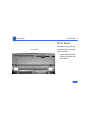
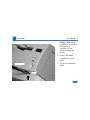
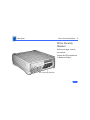
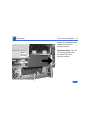
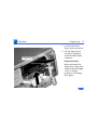
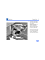
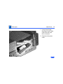
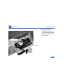
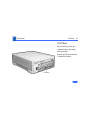
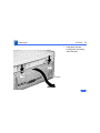
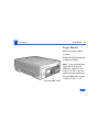
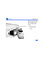
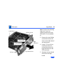
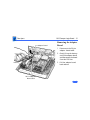
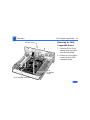
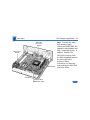
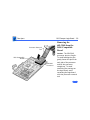
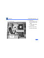
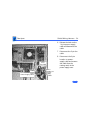
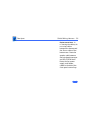
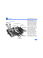
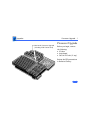
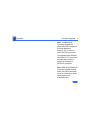
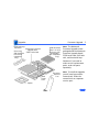
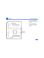
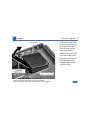
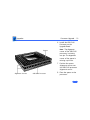
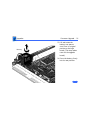
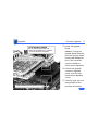
1
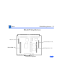
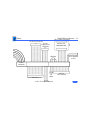
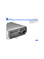
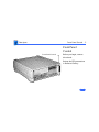
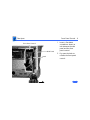
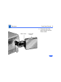
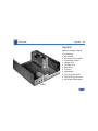
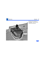
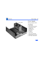
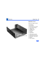
K Service Source
LC 630/Quadra 630/
Performa 640
Macintosh LC 630, Macintosh LC 630 DOS Compatible,
Macintosh Performa 640 DOS Compatible, Macintosh
Quadra 630
K Service Source
Basics
LC 630/Quadra 630/Performa 640
Basics
General Information - 2
General Information
Macintosh LC 630 and Macintosh Quadra 630
Computers
The Macintosh LC 630 and Macintosh Quadra 630 computers
are high- performance, low-cost modular computers with
multimedia features. The LC 630 uses the Motorola
68LC040 processor. The Quadra 630 uses the Motorola
68040, which includes a floating point unit. The computers
ship with the manual insert floppy drive, an IDE hard drive,
and an optional trayloading CD-ROM drive.
Basics
General Information - 3
Macintosh LC 630, DOS-Compatible
The LC 630 DOS-Compatible computer adds to the basic 630
design the ability to simultaneously run the Macintosh
operating system and PC application programs. The DOSCompatible computer ships with three boards and a DRAM
SIMM installed on the main logic board. The three boards
are the DOS-compatible board, a daughterboard for sound,
and a DOS-Compatible adapter board in the Processor Direct
Slot (PDS).
Basics
General Information - 4
Performa 640 DOS-Compatible
The Performa 640 DOS-Compatible is based on the
Macintosh LC 630-DOS Compatible computer.
The Performa 640 DOS-Compatible is bundled with a 500
IDE hard drive and the trayloading double-speed CD-ROM
drive.
As you go through this manual, consider the Macintosh LC
630 DOS-Compatible information as applicable to the
Performa 640 LC DOS-Compatible unless specified
otherwise.
Basics
General Information - 5
User Controls
User controls include:
• Soft power-on control from keyboard
• Front panel sound-control push buttons
• Optional infrared remote control
Basics
General Information - 6
Internal Expansion Connections
Four types of expansion slots on the logic board include:
• DRAM SIMM expansion slot (1 or 2 slots)
• LC PDS slot (already populated in the LC 630 DOSCompatible).
• Communications slot for modems and Ethernet
• Video-in slot for real-time video display, capture, and
overlay
In addition to expansion slots on the logic board, there is an
expansion ribbon connector for an optional TV tuner card.
The TV-tuner connector provides NTSC and PAL input from
an external TV antenna or cable.
Basics
General Information - 7
IDE (Intelligent Device Electronics)
The internal hard drive uses IDE (Intelligent Device
Electronics) technology, commonly used in DOS-compatible
systems.
The internal IDE hard drive functions the same as a typical
SCSI hard drive. You must replace IDE drives like for like.
The IDE drive does not affect SCSI ID selections or SCSI
termination schemes.
Seven external SCSI devices may be daisy chained through
the external SCSI port.
Basics
General Information - 8
Plastic Panel Design
The computer is designed for easy service. Plastic panels
cover the metal bottom case, the metal top cover shield, and
the left, right, and rear sides of the metal case.
To service the logic board, simply remove the rear plastic
panel and slide out the logic board. To access the drives,
simply remove the front plastic panel.
Basics
Rear View Diagram - 9
Rear View Diagram
TV Tuner
Access Cover
Monitor Port
Standby Power Button
Security
Lock Port
Power
Socket
Basics
I/O Door Diagrams - 10
I/O Door Diagrams
Video-In Card Access Cover
Communication Card
Access Cover
PDS Expansion Card
Access Cover
ADB Port
SCSI Port
Printer Port
Sound Output Port
Sound Input Port
Modem Port
630 Series Computers
Basics
Logic Board Diagrams - 11
Logic Board Diagrams
Video-In Card Access Cover
Communication Card
Access Cover
ADB Port
Printer Port
Modem Port
DB-15 DOSCompatibleAdapter Connector
SCSI Port
Sound Output Port
Sound Input Port
Basics
Shield/Wiring Harness - 12
Shield/Wiring Harness
Video-In Card
Communications Slot
DRAM SIMM Slot
PDS Expansion Slot
630 Series Computers
Basics
LC 630 DOS-Compatible Logic Board
Shield/Wiring Harness - 13
DOS-Compatible Board
Main Logic Board
DRAM SIMM
DOS-Compatible Adapter Board
DOS-Compatible Sound Board
Basics
Shield/Wiring Harness - 14
Basics
Shield/Wiring Harness - 15
DB-15 Video Connector
26-Pin IR Connector
20-Pin
Floppy Drive
Connector
Monitor-Out
Daughterboard
CD Audio
6-Pin Header
to P/S
Power
Connector
40-Pin IDE Connector
4-Pin
CD
Audio
10-Pin TV Tuner Connector
30-Pin
CD Connector
K Service Source
Specifications
LC 630/Quadra 630/Performa 640
Specifications
Processor - 2
Processor
LC 630
Quadra 630
LC 630 DOSCompatible
Addressing
Motorola 68LC040 microprocessor
33 MHz
Motorola 68040 microprocessor
(with floating point unit)
33 MHz
Motorola 68040, 33 MHz
80486DX2, 66 MHz
32-bit internal registers
32-bit address bus
32-bit data bus
Specifications
Memory - 3
Memory
DRAM
630 Series: 4 MB built in, 8 MB optional; expandable to 36 MB
(if logic board has only one SIMM slot, part number 6610158 ), or 52 MB (if logic board has two SIMM slots; one slot
is a regular SIMM slot and the other is a single-sided SIMM
slot, part number 661-1114).
LC 630 DOS-Compatible ships with 8 MB on main logic board (4
MB built in and 4 MB DRAM SIMM in one slot). Maximum
addressable memory is 52 MB on the main logic board (4 MB
built in, 32 MB SIMM in one slot and 16 MB SIMM the second
slot).
DOS Compatible board ships with 4 MB SIMM . Maximum
addressable memory is 32 MB on the DOS-Compatible board.
Main logic board and DOS Compatible board require 72-pin,
80 ns or faster SIMMs.
Specifications
DRAM Frame
Buffer
ROM
VRAM
Memory - 4
1 MB
1 MB
Video data are stored in the 1 MB DRAM frame buffer. The LC
630, Quadra 630, and LC 630 Dos-Compatible computers do
not support video memory expansion.
Specifications
Disk Storage - 5
Disk Storage
Floppy Drive
1.4 MB Apple SuperDrive Manual Insert
CD-ROM Drive
Optional Apple 300i Plus CD-ROM drive
Hard Drive
630 Series: 250 MB or 350 MB IDE hard drive
LC 630 DOS-Compatible: 500 MB IDE hard drive
Note: The internal IDE hard drive interface is new to Apple
products. Macintosh 630 computers do not support internal
SCSI hard drives.
Specifications
I/O Interfaces - 6
I/O Interfaces
Serial
Two RS-232/422 serial ports; mini DIN-8 connectors
SCSI
One external SCSI port; DB-25 connector
Supports up to six external SCSI devices
Apple Desktop Bus
One Apple Desktop Bus (ADB) port; mini DIN-4 connector
Video
One DB-15 monitor port on built-in video daughterboard
Specifications
Sound
Processor-Direct Slot
Communications
Slot
Video-In Slot
I/O Interfaces - 7
Mono sound input port supports external microphone or
line-level inputs
Bias current for electret microphone
Stereo sound output jacks at front and rear
630 Series: One 114-pin internal expansion slot for LC
compatible processor-direct card
LC 630 DOS-Compatible: An adapter board occupies the LC
processor-direct slot, providing a DB-15 connector for a PC/
AT game controller
One 112-pin internal expansion slot for modem and Ethernet
One 60-pin internal video-in slot for real-time video display,
capture, and overlay
Specifications
TV Tuner
Controls
I/O Interfaces - 8
One 10-pin slot for TV tuner card
Softpower-on control from keyboard
Front panel push button control for sound volume
Front panel stereo headphone jack
Optional infrared remote control
Specifications
I/O Devices - 9
I/O Devices
Keyboard
Apple Extended Keyboard II (other ADB keyboards supported)
Mouse
ADB Mouse II
Microphone
Electret, omnidirectional
Operates on 8 VDC supplied by sound input on CPU
Specifications
Sound and Video - 10
Sound and Video
Sound
Video
8-bit monophonic sound input
8-bit stereo sound output (16-bit in CD mode), level nominally
0.5 V RMS into 39 ohms
Internal speaker muted when a plug is inserted into an output jack
Supports all Apple 12-inch, 13-inch, and 14-inch monitors,
Apple 15-inch multiple synchronous monitor, and VGA (640 x
480) monitors at maximum 16-bit per pixel
Supports Apple 16-inch and SVGA (800 x 600) monitors at
maximum 8-bit per pixel
Specifications
Electrical - 11
Electrical
Line Voltage
Frequency
Maximum Power
100-240 VAC
50-60 Hz
45 W, not including monitor
Specifications
Physical - 12
Physical
Dimensions
Weight
Height: 4.3 in. (10.95 cm)
Width: 16.5 in. (41.95 cm)
Depth: 12.6 in. (32 cm)
Without CD-ROM: 17 lb. (7.7 kg)
With CD-ROM: 19 lb. (8.6 kg)
Weight varies with options
K Service Source
Troubleshooting
LC 630/Quadra 630/Performa 640
Troubleshooting
General - 1
General
The Symptom Charts included in this chapter will help you
diagnose specific symptoms related to your product. Because cures
are listed on the charts in the order of most likely solution, try
the first cure first. Verify whether or not the product continues to
exhibit the symptom. If the symptom persists, try the next cure.
(Note: If you have replaced a module, reinstall the original module
before you proceed to the next cure.)
If you are not sure what the problem is, or if the Symptom Charts
do not resolve the problem, refer to the Flowchart for the product
family.
For additional assistance, contact Apple Technical Support.
Troubleshooting
Symptom Charts/Error Chords - 2
Symptom Charts
Error Chords
Eight-tone error
chord sounds during
startup
1
2
3
4
Reseat SIMMs
Replace SIMMs.
Replace logic board. Retain customer’s SIMMs.
Perform SIMM verification on replacement logic board.
Four-tone error
chord sounds during
startup
1
Disconnect hard drive power cable and reboot system. If
startup sequence is normal, run “Macintosh Hard Disk Test”
and replace hard drive if necessary.
Disconnect floppy drive cable and reboot system. If startup
sequence is normal, replace floppy drive.
Replace logic board. Retain customer’s SIMMs.
2
3
Troubleshooting
Symptom Charts/System - 3
System
Flashing “?”
appears at startup in
system with vacant
PDS and
communication slots
1
4
5
Diagnose hard drive with Disk First Aid included on Power
Macintosh CD-ROM.
Perform repairs and then go to step 4.
If repairs are impossible, back up drive, reformat with
Drive Setup 1.0.3, and then go to step 4.
Update driver using Drive Setup 1.0.3.
Perform clean install
Menu bar constantly
flashes or system
constantly beeps
1
2
Verify that front panel control buttons are not jammed.
Reseat drive bezel and front panel control board.
2
3
Troubleshooting
Symptom Charts/Audio - 4
Audio
Crackling noise is
present when you
play sounds other
than system beeps
and you are not in
“play through” mode
1
This applies to DOScompatible
computers only:
Static through
speaker with optional
sound adapter board
installed and Internal
CD and Playthrough
option selected.
Replace the sound card, PN 661-0253.
2
If static noise varies when you adjust volume by Sound
control panel, use Audio Volume Extension 1.1 or later.
Note: Audio Volume Extension is available from standard
Apple software update sites.
Replace logic board.
Troubleshooting
Symptom Charts/Audio - 5
Audio
Sound distortion with
MPEG board installed
Replace MPEG board with modified MPEG board. A modified board
should have a jumper present from U5 Pin 2 to D1 Pin 1.
Troubleshooting
Symptom Charts/Video - 6
Video
Screen is dark, audio
and at least one drive
operate, fan runs,
and LED is lit
1
2
Video will not play or
system hangs when
you attempt to run
video in units with
MPEG card
1
3
4
5
6
7
2
Confirm that video connections are secure.
Confirm that monitor-out daughterboard connection on the
fan bracket is secure.
Reseat logic board.
Perform monitor adjustments
Replace monitor.
Replace logic board. Retain customer’s SIMMs.
Replace power supply.
If chip at location U12 on MPEG card displays number
341SO205, check all connections.
If chip at location U12 on MPEG card does not display
number 341SO205, replace MPEG card
Troubleshooting
Symptom Charts/Video - 7
Video
Screen is dark, audio
and drive do not
operate, but fan runs
and LED is lit
1
2
3
4
5
6
Reseat logic board.
Remove expansion card, if present.
Remove peripherals.
Replace SIMMs. Refer to Memory manual.
Replace logic board. Retain customer’s SIMMs.
Replace power supply.
Partial or whole
screen is bright and
audio is present, but
no video information
is visible
1
2
3
4
Reseat logic board.
Replace fan/video card bracket.
Replace monitor.
Replace logic board. Retain customer’s SIMMs.
Troubleshooting
Symptom Charts/Video - 8
Video
Screen is completely
dark, fan is not
running and LED is
not lit
1
2
3
4
5
6
7
8
9
Check all external power connections.
Computer powers on exclusively through softpower on
keyboard.
Verify that power-on connections of keyboard
are functioning by testing with known-good keyboard.
Reseat logic board.
Unplug 4.5 battery, wait 20 seconds, plug in battery, and
restart computer.
Verify that monitor has power.
Remove expansion card, if present.
Remove peripherals.
Replace power supply.
Replace logic board. Retain customer’s SIMMs.
Troubleshooting
Symptom Charts/Video - 9
Video
Vertical lines,
horizontal lines, or
snow appears on
screen, or screen is
completely dark;
startup tone is
normal
1
2
3
4
Unable to tune in some
UHF channels.
Replace Rev. A video-in card, part number 661-0159, with Rev.
B video-in card, part number 661-1073.
Perform monitor adjustments.
Replace monitor.
Replace logic board. Retain customer’s SIMMs.
Replace power supply.
Troubleshooting
Symptom Charts/Floppy Drive - 10
Floppy Drive
Audio and video are
present, but internal
drive does not operate
1
2
3
4
Reseat logic board
Replace floppy drive.
Replace shield/wiring harness
Replace logic board. Retain customer’s
Disk ejects; display
shows Mac icon with
blinking “X”
1
2
3
4
Replace disk with known-good system disk.
Replace floppy drive cable.
Replace floppy drive.
Replace logic board. Retain customer’s SIMMs.
Disk does not eject
1
Switch off system and hold mouse button down while
switching system back on.
Eject disk manually by pushing opened paper clip into hole
beside drive slot.
Replace floppy drive cable.
Replace floppy drive.
2
3
4
SIMMs.
Troubleshooting
Symptom Charts/Floppy Drive - 11
Floppy Drive
Drive attempts to
eject disk, but doesn’t
1
2
3
4
Switch off system and hold mouse button down while
switching system back on.
Eject disk manually by pushing opened paper clip into hole
beside drive slot.
Replace floppy drive cable.
Replace floppy drive.
Troubleshooting
Symptom Charts/Hard Drive - 12
Hard Drive
Internal hard drive
runs continuously
1
2
3
4
Make sure System is version 7.1.2 (or later).
Replace hard drive cable.
Replace internal hard drive.
Replace logic board. Retain customer’s SIMMs.
Internal hard drive
does not operate
1
2
3
4
5
Confirm that all hard drive connections are secure.
Reseat logic board.
Replace internal IDE hard drive.
Replace shield/wiring harness chassis.
Replace logic board. Retain customer’s SIMMs.
Hard drive not found
when booted from CDROM drive
Use Drive Setup 1.03.
Troubleshooting
Symptom Charts/CD-ROM drive - 13
CD-ROM drive
CD-ROM drive does
not accept disc
1
2
3
Replace disc (if dirty or damaged).
Reseat CD-ROM drive.
Replace CD-ROM drive.
Volume control does
not operate correctly
1
2
3
4
Check Control Panel Sound setting.
Check front panel controls.
Reseat front panel control board.
Replace shield/wiring harness chassis.
Macintosh cannot
mount CD-ROM drive
1
2
Reseat CD-ROM drive.
Check SCSI ID setting; internal CD-ROM drive was originally
set at 3 at the factory.
Replace CD-ROM drive.
3
Troubleshooting
Symptom Charts/Peripheral - 14
Peripheral
Works with internal
or external SCSI
device but does not
work with both
1
Cursor does not move
1
2
3
2
3
4
5
4
5
6
Verify that SCSI select switch on external device is set to
different priority from internal CD-ROM drive.
Verify that both ends of external SCSI device are terminated.
Replace terminator on external device.
Verify that terminator is installed on internal SCSI drive.
Replace SCSI select cable (on external SCSI device).
Reboot system.
Check mouse connection.
If mouse was connected to keyboard, connect mouse to rear
ADB port and disconnect keyboard. If mouse works, replace
keyboard.
If mouse does not work in ADB port, replace mouse.
Reseat logic board.
Replace logic board. Retain customer’s SIMMs.
Troubleshooting
Symptom Charts/Peripheral - 15
Peripheral
Cursor moves, but
clicking mouse
button has no effect
1
2
3
Replace mouse.
Reseat logic board.
Replace logic board. Retain customer’s SIMMs.
Double-click doesn’t
open application,
disk, or server
1
2
3
Remove extra system files on hard drive.
Check mouse speed on Control Panel
Unplug 5.4 battery, wait 20 seconds, plug in battery, and
restart computer.
If mouse was connected to keyboard, connect mouse to rear
ADB port and disconnect keyboard. If mouse works, replace
keyboard.
If mouse does not work in ADB port, replace mouse.
Replace logic board. Retain customer’s SIMMs.
4
5
6
Troubleshooting
Symptom Charts/Peripheral - 16
Peripheral
No response to any
key on keyboard
1
2
3
4
5
Make sure System is version 7.1.2 (or later).
Check keyboard connection to ADB port.
Replace keyboard.
Reseat logic board.
Replace logic board. Retain customer’s SIMMs.
Known-good
ImageWriter or
ImageWriter II does
not print
1
Make sure that Chooser and Control Panel settings are
correct.
Make sure System is version 7.1.2 (or later).
Check printer DIP switches.
Replace printer interface cable.
Replace logic board. Retain customer’s SIMMs.
2
3
4
5
Troubleshooting
Symptom Charts/Peripheral - 17
Peripheral
Known-good
LaserWriter does not
print
1
2
3
Make sure that Chooser and Control Panel settings are
correct.
Make sure System is version 7.1.2 (or later).
Refer to Networks manual.
Troubleshooting
Symptom Charts/Miscellaneous - 18
Miscellaneous
Rattling sound at
startup in system
with Apple External
Video Connector
Press or fold Apple External Video cable to prevent it from
contacting fan blades.
Troubleshooting
Symptom Charts/Global Village Modem “Busy Serial Port” - 19
Global Village Modem “Busy Serial Port”
Using modem gives
message: “Can’t find
or can’t access a
modem to use for
registration. Make
sure you have Global
Village software
installed correctly,
reboot your
computer, and try
again. If you want to
use a specific modem
for registration,
select it from
Chooser.”
The TelePort Control Panel becomes corrupted when a Performa
640CD is restarted while AppleTalk is set to “Inactive” in the
Chooser or LocalTalk is not the selected AppleTalk Connection in
the Network Control Panel. Follow these steps;
1
2
3
4
5
6
Obtain GlobalFax 2.5.2P Update.
Restart the computer with extensions off.
Double-click Performa GlobalFax 2.5.2 Update icon.
Click Update button and watch for update confirmation
window.
Restart computer.
Customer should keep backup copy of 2.5.2 Update program
and run it after reinstalling software from backup CD.
Troubleshooting
Symptom Charts/Global Village Modem “Busy Serial Port” - 20
Global Village Modem “Busy Serial Port”
Resetting modem in
TelePort Control
Panel gives message:
“The current port is
busy and cannot be
opened. Quit any open
communication
application, or turn
off AppleTalk in the
Chooser (if the
modem is connected to
the Printer port),
and then reopen the
TelePort control
panel.”
Here’s an alternative fix that doesn’t require GlobalFax 2.5.2P
Update:
1
2
Replace corrupted control panel in System Folder with
uncorrupted copy of TelePort Control Panel found in Control
Panels folder on backup CDs.
Set AppleTalk to “Active” and select LocalTalk as the
AppleTalk Connection in Network Control Panel.
K Service Source
Take Apart
LC 630/Quadra 630/Performa 640
Take Apart
Drive Bezel - 2
Drive Bezel
Drive Bezel
No preliminary steps are
required before you begin
this procedure.
1
Locate the two latches
below the ridge on the
drive bezel.
Take Apart
Drive Bezel - 3
2
Screwdriver
3
Latch
Caution: When using a
screwdriver to release a
latch, press up
carefully. Do not
scratch or gouge the
plastic.
Insert a flat-blade
screwdriver at each
latch.
Pry up to release each
latch.
Take Apart
Drive Bezel - 4
4
Drive Bezel
Swing up the drive bezel
and pull it away from the
metal chassis.
Take Apart
Front Panel Control - 5
Front Panel
Control
Front Panel Control
Before you begin, remove
drive bezel.
Review the ESD precautions
in Bulletins/Safety.
Take Apart
Front Panel Control - 6
1
Front Panel Control
Side Panel
Latch
2
Insert a flat-blade
screwdriver about an
inch between the side
panel and the front
panel control.
Pry open the latch to
release the front panel
control.
Take Apart
Front Panel Control - 7
3
Front Panel Control
Headphone Jack
Pull the front panel
control out just far
enough to reach the
ribbon cable connector.
Replacement Caution:
When you replace the
front panel control
assembly, make sure
that the headphone jack
is at the bottom of the
assembly.
Take Apart
Front Panel Control - 8
4
Ribbon Cable
Front Panel
Control
Disconnect the front
panel control from the
ribbon cable.
Take Apart
Drive Security Bracket - 9
Drive Security
Bracket
Before you begin, remove
drive bezel.
Review the ESD precautions
in Bulletins/Safety.
Drive Security Bracket
Take Apart
Drive Security Bracket - 10
Remove the mounting screw
and pull off the drive
security bracket.
Drive
Security
Bracket
Tab
Tab
Tab
Replacement Note: Be sure
to correctly position the
four tabs of the drive
security bracket.
Take Apart
Floppy Drive - 11
Floppy Drive
Before you begin, remove
the following:
• Drive bezel
• Drive security bracket
Review the ESD precautions
in Bulletins/Safety.
Floppy Drive
Take Apart
Floppy Drive - 12
1
2
Floppy Drive
Tab
Guide
Carrier
Lift the front of the
floppy drive and carrier.
Pull the floppy drive
out just far enough to
reach the ribbon cable
connector.
Replacement Note:
When you replace the
floppy drive, make sure
that the tab of the floppy
carrier is seated
properly in the floppy
drive guide.
Take Apart
Floppy Drive - 13
3
Floppy Drive Cable
Floppy Drive
Disconnect the floppy
drive from the floppy
drive cable.
Replacement Note: If
you are replacing a
defective floppy drive,
invert the drive and
carrier and remove the
four carrier mounting
screws. Separate the
drive from the carrier.
Take Apart
CD-ROM Drive - 14
CD-ROM Drive
Before you begin, remove
the following:
• Drive bezel
• Drive security bracket
Review the ESD precautions
in Bulletins/Safety.
CD-ROM Drive
Take Apart
CD-ROM Drive - 15
Note: To perform the next
procedure, you may want to
insert a screwdriver in the
slot of the release latch to
help you pull the CD-ROM
drive.
CD-ROM Drive
1
Release Latch
Push up the release latch
and pull the CD-ROM
drive from the chassis.
Note: You may need to
use some initial force to
disconnect the CD-ROM
from the internal wiring
harness.
Take Apart
CD-ROM Drive - 16
CD-Carrier
2
3
CD Audio Adapter
SCSI Adapter
4
Note: Perform the
following steps only if
you are replacing a
defective CD-ROM drive.
Disconnect the CD-ROM
audio adapter from the
drive.
Disconnect the SCSI
adapter.
Remove the four
mounting screws and
carrier from the CDROM drive.
Take Apart
CD-ROM Drive - 17
Replacement Caution:
Before replacing the
SCSI adapter, make sure
that the SCSI drive
connector pins are not
bent.
Take Apart
Hard Drive - 18
Hard Drive
Before you begin, remove
the following:
• Drive bezel
• Drive security bracket
Review the ESD precautions
in Bulletins/Safety.
Hard Drive
Note: The IDE hard drive
interface is new to Apple
products. LC 630 and Quadra
630 computers do not
support internal SCSI hard
drives. Refer to Basics for
more information.
Ê
Take Apart
Hard Drive - 19
1
2
Power Cable
IDE Data Cable
Using the pull tabs,
disconnect the IDE data
cable from the hard
drive connector.
Disconnect the power
cable.
Take Apart
Hard Drive - 20
3
IDE Hard Drive
Release Latch
Using a flat-blade
screwdriver, push up
the release latch and pull
the IDE hard drive from
the chassis.
Take Apart
I/O Door - 21
I/O Door
No preliminary steps are
required before you begin
this procedure.
Review the ESD precautions
in Bulletins/Safety.
I/O Door
Take Apart
I/O Door - 22
1
Tab
Tab
I/O Door
Push down the two
locking tabs and swing
down the door.
Take Apart
I/O Door - 23
Replacement Note:
Carefully align the
three hinge tabs before
swinging up the 1/0
door.
Hinge Tab
Hinge Tab
Hinge Tab
I/O Door
Take Apart
Logic Board - 24
Logic Board
Before you begin, remove
I/O door.
Review the ESD precautions
in Bulletins/Safety.
Logic Board with Fence
Note: If you are replacing a
logic board that has one
SIMM slot, replace it with
P/N 661-0158. If you are
replacing a logic board that
has two SIMM slots, replace
it with P/N 661-1114.
Take Apart
Logic Board - 25
Note: The 630 series
includes a variety of logic
board configurations. This
topic describes the logic
board removal procedures
common to all models in this
series. See “DOS-Compat.
Logic Board” topic, for
procedures specific to that
logic board. See Upgrades
chapter, “Processor
Upgrade” topic, for
procedures about the RISC
processor logic board
upgrade.
Ê
Take Apart
Logic Board - 26
1
Screw
Screw
Metal Fence
Remove the two screws
from the metal fence.
Take Apart
Logic Board - 27
Logic Board Fence
Logic Board
Note: The logic-board-andfence assembly may need a
firm initial tug to loosen it
from the shield/wiring
harness.
2
Slide out the logicboard-and -fenceassembly.
Take Apart
Logic Board - 28
Logic Board
Note: Perform the following
steps only if you are
replacing a defective logic
630 board. Do not attempt
to
Phillips Screw
3
Torx Screw
SCSI
Connector
Torx Screw
Phillips Screw
Logic Board Fence
4
5
Remove the two Phillips
screws that secure the
fence to the solder side of
the logic board.
Using a T9 torx driver,
remove the two torx
screws that secure the
logic board fence to the
SCSI connector.
Separate the logic board
fence from the logic
board.
Take Apart
DOS Compat. Logic Board - 29
DOS Compat.
Logic Board
Sound Board
Before you begin, remove
the following:
• I/O door
• Logic board
Adapter Board
Review the ESD precautions
in Bulletins/Safety.
Main Logic
Board
DRAM
SIMM
DOS-Compatible Board
Note: If you are replacing a
logic board that has one
SIMM slot, replace it with
P/N 661-0158. If you are
replacing a logic board that
has two SIMM slots, replace
it with P/N 661-1114.
Take Apart
DOS Compat. Logic Board - 30
Note: The LC 630 DOSCompatible logic board
includes the main logic
board with DRAM SIMM, the
DOS-Compatible board with
DRAM SIMM, DOSCompatible sound board,
DOS-Compatible adapter
board, and appropriate
cables.
Take Apart
DOS Compat. Logic Board - 31
Adapter Board
Removing the Adapter
Board
1
2
3
Battery
26-Pin Adapter
Board Cable
Disconnect the 26-pin
adapter board cable.
Gently lift up the battery
end of the adapter board
and disconnect the board
from the PDS slot.
Pull the adapter board
back and out.
Take Apart
DOS Compat. Logic Board - 32
Phillips Screws
4
5
6
Sound Board
Removing the Sound
Board
Remove the two Phillips
screws.
Lift the sound board to
disconnect and remove it.
Take Apart
DOS Compat. Logic Board - 33
Phillips Screw
Removing the DOSCompatible Board
1
2
DOSCompatible
Board
16-pin External Video Out
Disconnect the 16-pin
external video out cable
from the logic board.
Remove the four Phillips
screws from the DOScompatible board.
Take Apart
DOS Compat. Logic Board - 34
3
4
Ê
Caution: the DOScompatible board is
installed directly into
the ‘040 processor
socket. Use extreme
caution not to bend the
processor pins when
you remove the DOScompatible board from
the main logic board.
Gently loosen each side of
the DOS-compatible
board from the
processor socket.
Lift off the board.
Take Apart
DOS Compat. Logic Board - 35
Replacement Note: Return a
defective DOS-Compatible
board to Apple service with
the 68LC040 processor
installed.
Take Apart
DOS Compat. Logic Board - 36
68LC040
Processor
Socket
Main Logic
Board
DRAM SIMM
Standoffs
Standoff Nuts
(On Solder Side)
Note: To return the main
logic board to Apple,
remove the DRAM SIMM, the
standoffs, sound, adapter and
DOS- compatible boards. In
addition, transfer the
68LC040 processor from
the DOS-compatible board to
the main logic board
processor socket.
Procedures for removing
and installing the 68LC040
processor follow.
Take Apart
DOS Compat. Logic Board - 37
Removing the
Standoffs from the
Main Logic Board
Remove the four standoff
nuts from the solder side of
the main logic board and lift
off the standoffs.
Take Apart
DOS Compat. Logic Board - 38
Removing the
68LC040 from the
DOS-Compatible
Board
Processor Removal
Tool
DOS-Compatible
Board
68LC040
Processor
Caution: The 68LC040
processor pins are fragile.
To avoid bending the pins,
gently loosen the pins from
each side of the processor
and lift the processor
straight up. To avoid
scratching the tracings on
the logic board, avoid
contacting the logic board
with the processor removal
tool
Take Apart
DOS Compat. Logic Board - 39
1
2
Using the processor
removal tool, gently pry
up all four sides of the
680LC40 processor
from the DOScompatible board.
Lift the processor
straight up and remove
it.
Take Apart
DOS Compat. Logic Board - 40
Installing the
68LC040 processor in
the main logic board
socket.
Logic Board
Processor
Socket
Caution: The following
procedure protects the EMI
clips and avoids warping the
logic board and thus harming
the tracings.
1
Anti-static Foam
Ê
Support the processor
socket area of the main
logic board with several
thicknesses of antistatic foam.
Take Apart
Processor Alignment Corner
DOS Compat. Logic Board - 41
Note: A missing pin and pin
socket hole mark the
alignment corners of the
68LC040 processor and
socket.
2
Socket Alignment Corner
Locate the alignment
corners of the 68LC040
processor and the
processor socket.
Take Apart
DOS Compat. Logic Board - 42
Processor
Alignment
Corner
Socket
Alignment
Corner
Caution: Avoid bending the
processor pins when you
install the 68LC040
processor. If you meet
resistance, realign the pins
and standoffs.
3
4
Carefully position the
processor alignment
corner over the socket
alignment corner.
Press the pins firmly
into the socket.
Take Apart
Rear Panel - 43
Rear Panel
Rear Panel
No preliminary steps are
required before you begin
this procedure.
Take Apart
Rear Panel - 44
1
2
Screw
Screw
Remove the two Phillips
screws.
Lift off the rear panel.
Take Apart
Rear Panel - 45
Replacement Note:
Carefully align the flat tab
and the four hinge tabs.
Hinge Tabs
Flat
Tab
Take Apart
Top Cover - 46
Top Cover
Top Cover
Before you begin, remove
the following:
• Drive bezel
• Rear panel
Review the ESD precautions
in Bulletins/Safety.
Note: The top cover consists
of two parts that must be
removed separately, a
plastic cover on top of a
metal shield.
Take Apart
Top Cover - 47
1
Plastic Top Cover
2
Cutout
3
Plastic Stops
Insert a small flatblade screwdriver into
the cutout and lift the
front edge to clear the
plastic stops.
With your other hand,
slide the plastic cover
forward about one-half
inch.
Lift the plastic cover off
the metal shield.
Take Apart
Top Cover - 48
4
Phillips Screw
5
Phillips Screw
Metal Shield
Remove the two Phillips
screws.
Slide the metal shield
toward the front of the
unit about one-half inch.
Take Apart
Top Cover - 49
Metal Shield
6
7
Security Wire
8
9
Floppy Drive Cable
Lift the front edge of the
metal shield about an
inch.
Under the metal shield,
squeeze together the ends
of the floppy drive cable
security wire and
unhook it from the
metal shield.
Remove the security
wire from the floppy
drive cable.
Lift off the metal shield.
Take Apart
Shield/Wiring Harness - 50
Shield/Wiring
Harness
Shield/Wiring Harness
Before you begin, remove
the following:
• D r ive bezel
• Drive security bracket
• Front panel control
• Floppy drive
• CD-ROM drive
• Hard drive
• I/O door
• Logic board
• Rear panel
• Top cover and shield
Review the ESD precautions
in Bulletins/Safety.
Take Apart
Shield/Wiring Harness - 51
1
2
Plastic Side Panel
Push in and slide the
plastic side panels
toward the front of the
computer about onehalf inch.
Remove the plastic side
panels.
Take Apart
Shield/Wiring Harness - 52
Note: This graphic shows
the bottom case tipped to
provide a better view of the
screw. Perform this
procedure with the bottom
case seated on a firm, flat
surface.
3
Screw
Shield/Wiring Harness
Remove the screw that
secures the shield/
wiring harness to the
bottom case.
Take Apart
Shield/Wiring Harness - 53
4
2-Pin Speaker Cable
Cable Holder
5
10-Pin Tuner Cable
34-Pin
Monitor-Out
Cable
Disconnect:
• 2-pin speaker cable
• 34-pin monitor-out
cable
• 10-pin tuner cable,
if connected
Slide the tuner cable
from the cable holder.
Take Apart
Shield/Wiring Harness - 54
6
7
8
2-Pin
Fan Cable
Latch
14-Pin
Power Supply Cable
6-Pin
Header-toPowerSupply
Cable
Release the latch on the
14-pin power supply
cable and disconnect the
cable.
Disconnect the 2-pin fan
cable.
Disconnect the 6-pin
header-to-powersupply cable and remove
the cable from the
routing notch in the
power supply case.
Take Apart
Shield/Wiring Harness - 55
Shield/Wiring
Harness
Front Panel
Control Bay
9
Lift up one side of the
shield/wiring harness a
few inches, then lift up
the other side about an
inch.
Note: Guide the speaker
cable through the shield/
wiring harness as you
remove the harness.
10 Remove the shield/
wiring harness.
Logic Board
Connector
CD-ROM Shelf
Take Apart
Shield/Wiring Harness - 56
Replacement Note: In
re-routing the cables, do
not crimp cables
between the harness and
the floor or sides of the
bottom case. Route the
speaker cable between
the logic board connector
and the CD-ROM shelf.
Route the fan, power
supply, and header
cables to the side of the
front panel control bay.
Take Apart
MonitorOut Cable
Shield/Wiring Harness - 57
Video-In Cable
Power Supply Cable
Floppy Drive
Cable
6-Pin
Header-toFront Panel
Control Cable
Hard Drive
Power Cable
IDE Data Cable
Replacement Note: Arrange
the cables as shown before
replacing the shield/wiring
harness. When dressing the
cables, do not crimp them
between the harness and the
floor of the bottom case, or
between the harness and the
sides of the bottom case.
Route the speaker cable
between the logic board
connector and the CD-ROM
shelf. Route front panel
control, power supply, and
header cables to the side of
the front panel control bay.
Ê
Take Apart
Tab
Shield/Wiring Harness - 58
Tab
Tab
Tab
Tab
Tab
Replacement Note:
Carefully position all six
tabs of the shield/wiring
harness.
Take Apart
Fan/Video Card Bracket
Fan/Video Card Bracket - 59
Fan/Video Card
Bracket
Before you begin, remove
the following:
• I/O door
• Drive bezel
• Top cover and shield
Review the ESD precautions
in Bulletins/Safety.
Take Apart
Fan/Video Card Bracket - 60
1
Screw
Screw
Logic Board
Metal Fence
Remove the two screws
from the logic board
metal fence.
Take Apart
Fan/Video Card Bracket - 61
2
2-Pin Speaker Cable
Cable Holder
3
10-Pin Tuner Cable
34-Pin
MonitorOut Cable
Disconnect:
• 2-pin speaker cable
• 34-pin monitor-out
cable
• 10-pin tuner cable,
if connected
Slide the tuner cable
from the cable holder.
Take Apart
Fan/Video Card Bracket - 62
4
2-Pin
Fan Cable
Disconnect the 2-pin fan
cable.2-Pin Fan Cable
Take Apart
Fan/Video Card Bracket
Fan/Video Card Bracket - 63
5
6
Lift up one side of the
fan/video card bracket,
then the other.
Remove the fan/video
card bracket.
Take Apart
Speaker - 64
Speaker
Before you begin, remove
the following:
• Drive bezel
• Drive security bracket
• Front panel control
• Floppy drive
• CD-ROM drive
• Hard drive
• I/O door
• Logic board
• Top cover and shield
• Shield/Wiring harness
• Fan/Video card bracket
Speaker
Ê
Take Apart
Speaker - 65
Pull up on the speaker to
disengage it from its hookand-loop connection.
Speaker
Take Apart
Power Supply - 66
Power Supply
Power Supply
Before you begin, remove
the following:
• Drive bezel
• Drive security bracket
• Front panel control
• Floppy drive
• CD-ROM drive
• Hard drive
• I/O door
• Logic board
• Top cover and shield
• Shield/Wiring harness
• Fan/Video card bracket
Ê
Take Apart
Power Supply - 67
Remove the screw from the
power supply and lift the
power supply from the
bottom case.
Power Supply
Screw
Take Apart
Bottom Case - 68
Bottom Case
Bottom Case
Before you begin, remove
the following:
• Drive bezel
• Drive security bracket
• Front panel control
• Floppy drive
• CD-ROM drive
• Hard drive
• I/O door
• Logic board
• Top cover and shield
• Shield/Wiring harness
• Fan/Video card bracket
• Speaker
• Power supply
K Service Source
Upgrades
LC 630/Quadra 630/Performa 640
Upgrades
Processor Upgrade - 1
Macintosh Processor Upgrade
(including 256K Cache Card)
Processor Upgrade
Before you begin, remove
the following:
• I/O door
• Logic board
• Card in PDS slot (if any)
Review the ESD precautions
in Bulletins/Safety.
Upgrades
Processor Upgrade - 2
Note: The Macintosh
Processor Upgrade kit
allows 68LC040 computers
to switch between a
PowerPC 601 processor
and a 68LC040 processor.
The upgrade board includes
the PowerPC 601 processor
on board and a socket to
accept the customer’s
68LC040 processor.
Note: Refer to the Macintosh
Processor Upgrade manual
under the Power Macintosh
menu for information about
specifications and
troubleshooting.
Upgrades
Processor Upgrade - 3
Hook-and-Loop
Fasteners
Macintosh Processor
Upgrade with
(Use in LC
256K Cache Card
and Performa
500 Series
computers
only.)
Spacer
040 Heat Sink
(Use in LC 475,
Performa 47X,
and Quadra
605 computers
only.)
256K
Cache
Card
Processor
Removal
Tool
Note: The Macintosh
Processor Upgrade comes
packaged with the Macintosh
Processor Upgrade board,
256K cache card, 040 heat
sink, and hook-and-loop
fasteners. If you need to
order service replacement
parts, order the parts
separately.
Note: To install the upgrade,
you will need a processor
removal tool. Order the
removal tool as a separate
service part.
Upgrades
Processor Upgrade - 4
Note: The cache card comes installed on the upgrade board.
Upgrades
Processor Upgrade - 5
Installation Procedure
Overview
There are four basic steps to
installing the Macintosh
Processor Upgrade.
• Remove the 68LC040
processor from the
customer’s logic board
• Install the 68LC040
processor on the upgrade
board
• Prepare the upgrade and
logic boards for
installation
• Install the upgrade board
on the logic board
Upgrades
Processor Upgrade - 6
Detailed procedures for this
computer follow.
Upgrades
Processor Upgrade - 7
1
68LC040 Processor
2
68LC040
Processor
Remove the 68LC040
Processor from the Logic
Board
Locate the 68LC040
processor on the logic
board.
Upgrades
Processor Upgrade - 8
3
Processor
Position the teeth of the
processor removal tool
in the groove between
the processor and the
logic board socket.
Caution: Be sure to lift
up on the handle of the
processor removal tool.
Pressing down could
damage components on
the logic board.
Logic Board Socket
Note: This graphic shows the proper way to
remove any 68LC040 chip from its logic board.
Your logic board may differ somewhat from this graphic
Upgrades
Processor Upgrade - 9
4
5
Caution: Pry up each
side of the processor
only slightly to avoid
bending the pins.
Gently lift up the
processor removal tool
handle and pry up each
side of the processor
from the socket.
Remove the processor.
Upgrades
Processor Upgrade - 10
6
Spacer
7
Alignment Corners
68LC040 Processor
8
Ê
Install the 68LC040
Processor on the
Upgrade Board
Note: The alignment
corner of the 68LC040
processor is missing
one pin. The alignment
corner of the spacer is
missing a pin hole.
Position the spacer
alignment corner over
the 68LC040 processor
alignment corner
Place the spacer on the
processor.
Upgrades
Processor Upgrade - 11
Caution: Forcing the
68LC040 processor
connector pins into the
socket could damage the pins.
If the processor resists
installation, check the pin
alignment.
68LC040 Processor
Caution: Place the upgrade
board on a firm even surface
to avoid bending the upgrade
board when pressing the
processor into the socket.
Caution: Use two thumbs to
evenly distribute the
pressure as you press the
processor into the socket.
Upgrades
Processor Upgrade - 12
9
Hold the processor and
spacer together and
position the spacer
alignment corner over
the upgrade socket
alignment corner.
10 Press the processor
connector pins into the
socket until you hear a
“snap.”
Upgrades
Processor Upgrade - 13
040 Processor
Small Gap
Spacer
Barrel Sockets
Note: On a correctly
installed 040 processor, a
very small gap separates the
040 chip from the metal
spacer. A larger gap caused
by the barrel sockets of the
upgrade board separates the
upgrade board and the
spacer.
Upgrades
Processor Upgrade - 14
11 Prepare the Upgrade and
Logic Boards for
Installation
Antistatic Foam
Logic Board,
Bottom Side
Note: The following
steps explain how to
prepare the logic board
to accept the upgrade
board.
Caution: The EMI clips
on the bottom of logic
board are fragile. Do
not apply heavy
pressure directly to
these clips or you may
bend the logic board.
Upgrades
Processor Upgrade - 15
12 Place a piece of
antistatic foam directly
under the processor
socket on the bottom
side of the logic board.
Note: This step helps
prevent the logic board
from bending when you
apply pressure in the
next few steps.
Upgrades
Battery
Processor Upgrade - 16
13 Lift and rotate the
battery one quarter
turn from its original
position on the logic
board. (This step makes
room for the upgrade
board.)
14 Press the battery firmly
into its new position.
Upgrades
Processor Upgrade - 17
LATE DESIGN CHANGE
Do not add the 040 heat sink
when you upgrade an LC, Quadra,
or Performa 630 computer.
Upgrade Connector Alignment Corner
15 Install the Upgrade
Board
Caution: Forcing the
upgrade board connector
pins into the logic board
socket could damage the
pins. If the connector
resists installation,
check the pin alignment.
16 Position the upgrade
connector alignment
corner over the logic
board socket alignment
corner.
Logic Board Socket Alignment Corner
17 Carefully align the pins
along all sides of the
processor and socket.
Upgrades
Processor Upgrade - 18
18 Firmly press the
connector pins into the
logic board socket.
Note: To install the
software, refer to the
upgrade Owner’s Guide.
Upgrades
Processor Upgrade - 19
Logic Board and
Upgrade Board
Returns
Return the upgrade and
logic boards to their original
conditions before sending
them to Apple. Be sure to
remove the upgrade board
from the logic board and
reinstall the 68LC040
processor on the logic board.
Replacement Caution: To
avoid bending any pins when
removing the 68LC040
processor, pry up each side
only slightly.
Upgrades
PowerMacintosh 5300/6300 Logic Board Upgrade - 20
PowerMacintosh
5300/6300 Logic
Board Upgrade
Before you begin, remove
the following:
• I/O door
• Logic board
• Card in PDS slot (if any
Caution: Use a grounded
workbench and always wear
a grounding wriststrap.
Note:
This upgrade is not
supported by DOSCompatible systems.
Upgrades
PowerMacintosh 5300/6300 Logic Board Upgrade - 21
The Power Macintosh 5300/6300 Logic Board Upgrade is a
finished goods product. The upgrade kit includes the 603e,
100 MHz logic board and logic board fence. See Take Apart
chapter, Logic Board topic for installation procedures.
Service Provider’s Checklist
•
•
•
•
•
•
Install the upgrade board
Run Safe Install
Install System 7.5
Turn on the upgrade board
Turn on Modern Memory Manager
Restart the computer to verify the board works properly
Replacement Note: You may need to remove the 603e
processor on the 6300 series logic board to install or
service SIMMs. See “6300 SIMM Upgrade.”
K Service Source
Exploded View
Macintosh LC/Quadra 630, P 640
Exploded View
1
Exploded View
Top Cover
922-1161
Shield
922-1155
Front Panel
Control Board
661-0139
Wiring Harness
922-1154
Floppy
Drive
661-0121
Chassis Shield
922-1154
Floppy
Drive
Carrier
922-1133
Drive
Security
Bracket
922-1156
Hard Drive
661-0070 (250 MB)
661-0068 (350 MB)
661-0146 (500 MB)
Fan/Video
Bracket
922-1160
I/O Door
922-2439
Processor
Upgrade Card
661-0255
CD-ROM Drive
661-0913
Hard Drive
Carrier
922-1124
Logic Board
Fence
922-2314
CD-ROM
Carrier
922-0850
Side Panel
922-1159
Logic Board
661-0158 (non-DOS)
661-0189 (Q630)
661-1114 (DOS)
661-1115
(DOS International Only)
Power Supply
661-0170
Side Panel
922-1158
Bottom Case
922-1176
Speaker
922-1175
Product family configurations may vary.
Front Bezel
922-1157
(Tray CD, Manual Insert Floppy)
922-1508
(DOS)