1
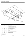
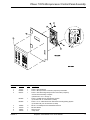
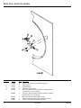
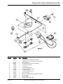
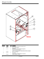
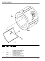
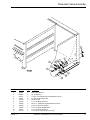
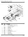
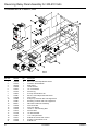
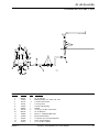
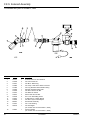
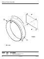
D90 Parts Manual
Phase 7
JLA Limited
Meadowcroft Lane, Halifax Road
Ripponden
West Yorkshire, England
HX6 4AJ
Telephone: 01422 822282 / Fax: 01422 824390
Part No. 450595-2
Retain This Manual In A Safe Place For Future Reference
This product embodies advanced concepts in engineering, design, and safety. If this product is properly maintained, it will
provide many years of safe, efficient, and trouble-free operation.
ONLY qualified technicians should service this equipment.
OBSERVE ALL SAFETY PRECAUTIONS displayed on the equipment or specified in the installation manual included with
the dryer.
The following “FOR YOUR SAFETY” caution must be posted near the dryer in a prominent location.
FOR YOUR SAFETY
POUR VOTRE SÉCURITÉ
Do not store or use gasoline or
other flammable vapors and
liquids in the vicinity of this or
any other appliance.
Ne pas entreposer ni utiliser d’essence
ni d’autres vapeurs ou liquides
inflammables à proximité de cet appareil
ou de tout autre appareil.
We have tried to make this manual as complete as possible and hope you will find it useful. The manufacturer reserves
the right to make changes from time to time, without notice or obligation, in prices, specifications, colors, and material,
and to change or discontinue models.
Important
For your convenience, log the following information:
DATE OF PURCHASE ____________________________________________________
D90 PH7
MODEL NO. ______________
DISTRIBUTOR’S NAME _______________________________________________________________________________
SERIAL NUMBER(S) __________________________________________________________________________________
____________________________________________________________________________________________________
____________________________________________________________________________________________________
Replacement parts can be obtained from your distributor or JLA. When ordering replacement parts from the factory,
you can FAX your order to JLA at 01422 824390 or telephone your order directly to the JLA Parts Department at
01422 822282. Please specify the dryer model number and serial number in addition to the description and part
number, so that your order is processed accurately and promptly.
The illustrations on the following pages may not depict your particular dryer exactly. The illustrations are a composite of the
various dryer models. Be sure to check the descriptions of the parts thoroughly before ordering.
“IMPORTANT NOTE TO PURCHASER”
Information must be obtained from your local gas supplier on the
instructions to be followed if the user smells gas. These
instructions must be posted in a prominent location near the dryer.
Table of Contents
Control Door Assembly................................................................................................................. 4
Phase 7 OPL Microprocessor Control Panel Assembly ............................................................... 5
Main Door / Front Panel Assembly ............................................................................................... 6
Main Door Assembly .................................................................................................................... 7
Main Door Switch Assembly ......................................................................................................... 8
Temperature Sensor Bracket Assembly ....................................................................................... 9
Wrapper Assembly ..................................................................................................................... 10
Lint Drawer Assembly ................................................................................................................. 11
Tumbler Assembly ...................................................................................................................... 12
Phase 7 Rotational Sensor Assembly ........................................................................................ 13
Idler Shaft Assembly .................................................................................................................. 14
Drive Shaft Assembly ................................................................................................................. 15
Drive Motor Assembly ................................................................................................................ 16
Direct Spark Ignition Burner Assembly ....................................................................................... 18
Motorized Impellor (Fan) Assembly ............................................................................................ 20
Pneumatic Valve Assembly ........................................................................................................ 21
Reversing Relay Panel Assembly for Models Mfd. prior to February 10, 2006 .......................... 22
Reversing Relay Panel Assembly for 208-240 Volts for Models Mfd. as of February 10, 2006 . 23
Reversing Relay Panel Assembly for 380-416 Volts for Models Mfd. as of March 2, 2006 ........ 24
Reversing Relay Panel Assembly for 460-480 Volts for Models Mfd. as of March 2, 2006 ........ 25
Air Jet Assembly for Models Mfd. prior to April 2, 2004 .............................................................. 26
Air Jet Assembly for Models Mfd. as of April 2, 2004 ................................................................. 27
Sail Switch Assembly ................................................................................................................. 28
F.S.S. Temperature Probe Assembly .......................................................................................... 29
F.S.S. Solenoid Assembly for Models Mfd. prior to October 2, 2002 .......................................... 30
F.S.S. Solenoid Assembly for Models Mfd. as of October 2, 2002 ............................................. 31
Exhaust Collar Assembly ............................................................................................................ 32
Control Door Assembly
Illus. No.
Part No.
Qty.
1
816672
1
883293*
1
117603
117604
150314
154011
———**
150309
102603
102601
102502
2
4
2
2
1
4
1
1
1
2
3
4
5
6
7
8
9
10
Description
Phase 7 Control Door
(for models mfd. as of November 27, 2001)
Phase 7 Control Door with Hinge
(for models mfd. prior to November 27, 2001)
(includes illus. nos. 2 and 3)
1/8” x 9/16” Noise Suppressor Tape
Neoprene Sponge Tape (sold by the foot)
#10-32 x 1/2” TORX® Screw
#10-32 Multi-Thread U-Nut
Logo ONLY
#10-16 x 1/2” Hex Head TEK Crimptite Screw
Control Door Rod Support Catch
Control Door Retainer Clip
Control Door Rod
* Specify color when ordering.
** Contact distributor for logo.
4
JLA Limited
450595 - 2
Phase 7 OPL Microprocessor Control Panel Assembly
Illus. No.
Part No.
Qty.
1
2
3
112577
850984
822767
1
1
1
887005
1
887002
1
150005
153010
136097
136016
2
2
1
1
4
5
6
7
450595 - 2
Description
Phase 7 OPL Keyboard
Phase 7 Microprocessor Controller (computer) Panel ONLY
Phase 7 OPL Reversing Microprocessor Controller (computer)
Control Panel Assembly Complete
(includes illus. nos. 1 through 7)
Phase 7.2.2 BD with Fire Suppression System
(for models mfd. as of December 3, 2003)
Phase 7.2.1 to .2 BD with Sensor Activated Fire Extinguishing System
(for models mfd. prior to December 3, 2003)
#6-32 x 3/4” Phillips Round Head Machine Screw
#6 Star Washer
500-mA Fuse
5-Amp Fuse
Telephone: 01422 822282 / Fax: 01422 824390
5
Main Door / Front Panel Assembly
Illus. No.
Part No.
Qty.
1
––––––
1
2
3
150443
881441
882283
153031
150443
881440
882284
801614
882236
2
1
1
1
2
1
1
1
1
882345
1
8
9
10
––––––
116326
––––––
1
1
1
11
12
182507
––––––
2
1
13
14
170330
154215
1
2
4
5
6
7
6
Description
Main Door
(refer to Main Door Assembly on page 7)
Socket Cap Screw
Bottom Hinge Block (white)
Bottom Hinge Block (wrinkle coral blue)
Nylon Washer
Socket Cap Screw
Top Hinge Block (white)
Top Hinge Block (wrinkle coral blue)
Magnet Door Front Panel
Front Panel (white)
(includes illus. nos. 7, 13, and 14)
Front Panel Assembly (wrinkle coral blue)
(includes illus. nos. 7, 13, and 14)
Emblem
Front Panel Insulation
Main Door Switch
(refer to Main Door Switch Assembly on page 8)
1/4-20 High Crown Acorn Nut
Lint Screen
(refer to Lint Drawer Assembly on page 11)
Friction Door Latch
5/32 x 1/4” Rivet
JLA Limited
450595 - 2
Main Door Assembly
Illus. No.
Part No.
Qty.
1
801600
1
881968
1
882292
1
881966
882305
102214
881685
882296
881740
882339
881688
882295
881806
882293
152008
150120
102357
151012
1
1
1
1
1
6
6
1
1
6
6
1
1
1
4
2
3
4
5
6
7
8
9
10
450595 - 2
Description
Cold Rolled Steel Magnet Main Door Assembly
(for models mfd. as of July 21, 2005)
Cold Rolled Steel Main Door Assembly (white)
(includes illus. nos. 1 through 10)
Cold Rolled Steel Main Door Assembly (wrinkle coral blue)
(includes illus. nos. 1 through 10)
Cold Rolled Steel Large Main Door Ring (white)
Cold Rolled Steel Large Main Door Ring (wrinkle coral blue)
30” Main Door Glass
Main Door Hinge (white)
Main Door Hinge (wrinkle coral blue)
1/4-20 x 5/8” Carriage Bolt (white)
1/4-20 Carriage Bolt (wrinkle coral blue)
Main Door Handle (white)
Main Door Handle (wrinkle coral blue)
1/4-20 Free Spin Wash Nut (white)
1/4-20 Free Spin Wash Nut (wrinkle coral blue)
#10-32 Hex Nut
Door Latch Screw
7/8” x 7/8” x 104” Door Gasket
#10-32 Nylon Acorn Nut
Telephone: 01422 822282 / Fax: 01422 824390
7
Main Door Switch Assembly
Illus. No.
Part No.
Qty.
1
2
3
4
5
150006
152013
153010
137005
881702
2
2
2
1
1
882298
1
881687
882291
150301
1
1
2
6
8
Description
#6-32 x 7/8” Phillips Pan Head Machine Screw
#6-32 Hex Nut
#6 Star Washer
Main Door Switch ONLY
Main Door Switch Housing Assembly Complete (white)
(includes illus. nos. 1 through 5)
Main Door Switch Housing Assembly (wrinkle coral blue)
(includes illus. nos. 1 through 5)
Main Door Switch Housing ONLY (white)
Main Door Switch Housing ONLY (wrinkle coral blue)
#8-18 x 7/16” Phillips Pan Head TEK Screw
JLA Limited
450595 - 2
Temperature Sensor Bracket Assembly
Illus. No.
Part No.
Qty.
1
859372
1
2
3
4
5
6
7
8
9
10
11
12
13
881089
880252
154007
121028
122701
122605
122700
122604
130302
150005
153010
152013
152014
1
1
2
1
4
1
4
1
1
2
2
2
2
450595 - 2
Description
Temperature Sensor Bracket Complete
(includes illus. nos. 1 through 6 and 9 through 12)
Sensor Bracket
4” Temperature Sensor Probe Assembly
1/4” Push-On Fastener
1/4” Terminal
Socket Terminal ONLY
4-Position Female Connector
Pin Terminal ONLY
4-Position Male Connector
225° Thermostat
#6-32 x 1/4” Phillips Round Head Machine Screw
#6 Star Washer
#6-32 Hex Nut
1/4-20 Free Spin Wash Nut
Telephone: 01422 822282 / Fax: 01422 824390
9
Wrapper Assembly
Illus. No.
Part No.
Qty.
Description
1
2
3
150309
859367
––––––
20
1
1
4
––––––
1
5
6
859368
––––––
1
1
7
122116
1
#10-16 x 1/2” Hex Head TEK Crimptite Screw
Bottom Right Wrapper
Idler Shaft
(refer to Idler Shaft Assembly on page 14)
Temperature Sensor Bracket
(refer to Temperature Sensor Bracket Assembly on page 9)
Bottom Left Wrapper
Drive Shaft
(refer to Drive Shaft Assembly on page 15)
Lint Door Switch – 24 VAC
10
JLA Limited
450595 - 2
Lint Drawer Assembly
Illus. No.
Part No.
Qty.
1*
883305
1
2
3
115902
154215
1
5
Description
Lint Drawer Assembly
(includes illus. nos. 1 through 3)
Lint Basket Felt
5/32 x 1/4” Rivet
* Specify color when ordering.
450595 - 2
Telephone: 01422 822282 / Fax: 01422 824390
11
Tumbler Assembly
Illus. No.
Part No.
Qty.
1
835002
1
859389
1
333670
4
882234
4
150118
24
2
3
12
Description
Tumbler Assembly Complete
(for models mfd. as of April 9, 2007)
(includes illus. nos. 1 through 3)
Tumbler Assembly Complete
(for models mfd. prior to April 9, 2007)
(includes illus. nos. 1 through 3)
Perforated Tumbler Panel
(for models mfd. as of April 9, 2007)
Perforated Tumbler Panel
(for models mfd. prior to April 9, 2007)
1/4-20 x 1/4” Phillips Pan Head Screw
JLA Limited
450595 - 2
Phase 7 Rotational Sensor Assembly
Illus. No.
Part No.
Qty.
1
819064
1
2
3
4
5
6
7
8
9
10
835339
102394
153005
150619
153004
180018
819046
819065
822735
152005
1
2
6
2
8
2
1
1
1
4
450595 - 2
Description
Tumbler Shaft Support Assembly Complete
(includes illus. nos. 1 through 8)
Tumbler Shaft Support Bracket
Tumbler Friction Pad
3/8” Lock Washer
3/8-16 x 1” Tap Bolt
3/8” Flat Washer
4” x 1-1/2” Hi-Impact Wheel
Tumbler Adjustment Plate
Tumbler Shoulder Screw
Phase 7 Rotational Sensor Assembly
3/8-16 Hex Nut
Telephone: 01422 822282 / Fax: 01422 824390
13
Idler Shaft Assembly
Illus. No.
Part No.
Qty.
1
859328
1
2
3
4
5
6
7
8
9
10
390232
180033
180038
880205
152004
153002
153001
859008
859327
150509
1
2
2
2
4
4
4
2
2
4
14
Description
Idler Shaft Assembly Complete
(includes illus. nos. 1 through 10)
Idler Shaft ONLY
6” Wheel
1” Taper Lock Bushing
1” Pillow Block Bearing
5/16-18 Hex Nut
5/16” Lock Washer
5/16” Flat Washer
Bearing Bolt Plate Assembly
Bearing Pad
5/16-18 x 3” Tap Bolt
JLA Limited
450595 - 2
Drive Shaft Assembly
Illus. No.
Part No.
Qty.
1
859329
1
2
3
4
5
6
7
8
9
10
11
390243
180033
180038
880205
152004
153002
153001
859008
859327
150509
101209
1
2
2
2
4
4
4
2
2
4
1
450595 - 2
Description
Drive Shaft Assembly Complete
(includes illus. nos. 1 through 11)
Drive Shaft ONLY
6” Wheel
1” Taper Lock Bushing
1” Pillow Block Bearing
5/16-18 Hex Nut
5/16” Lock Washer
5/16” Flat Washer
Bearing Bolt Plate Assembly
Bearing Pad
5/16-18 x 3” Tap Bolt
9” Pulley
Telephone: 01422 822282 / Fax: 01422 824390
15
Drive Motor Assembly
16
JLA Limited
450595 - 2
Drive Motor Assembly
Illus. No.
Part No.
Qty.
1
882245
1
2
3
4
5
6
7
8
9
10
11
12
882237
152004
150501
153001
153002
181106
100174
101132
150501
153002
153001
150523
1
4
3
3
3
1
1
1
4
8
8
1
450595 - 2
Description
Drive Motor Assembly Complete
(includes illus. nos. 1, 2, 6, and 9 through 11)
Motor Mount ONLY
5/16-18 Hex Nut
5/16-18 x 3/4” Tap Bolt
5/16” Flat Washer
5/16” Lock Washer
1/2 hp 208-480v (3ø) 50/60 Hz Drive Motor
AX-53 Cogged V-Belt
5/8” x 2” Motor Pulley
5/16-18 x 3/4” Tap Bolt
5/16” Lock Washer
5/16” Flat Washer
1/4-20 x 3/4” Hex Washer Machine Bolt
Telephone: 01422 822282 / Fax: 01422 824390
17
Direct Spark Ignition Burner Assembly
18
JLA Limited
450595 - 2
Direct Spark Ignition Burner Assembly
Illus. No.
Part No.
Qty.
15
16
17
18
19
20
21
142924
331291
150309
142735
142601
142504
142734
150309
390125
887159
887155
140411
150415
331291
141219
140862
140818
150309
141123
150309
390124
150309
150309
821456
1
1
2
1
1
1
1
2
1
1
1
1
2
1
1
3
3
2
3
2
1
2
6
1
22
23
24
25
26
27
28
29*
331289
150309
128914
150001
151000
130201
319703
882677
1
2
1
2
2
1
1
1
882678
1
859374
335031
883844
1
1
1
1
2
3
4
5
6
7
8
9
10
11
12
13
14*
30
31
Description
1” to 3/4” Reducing Coupling
Gas Valve Pipe Bracket
#10-16 x 1/2” Hex Head TEK Crimptite Screw
3/4” x 14” Bi Nipple
3/4” Union
3/4” x 90° Elbow
3/4” x 5-1/2” Nipple
#10-16 x 1/2” Hex Head TEK Crimptite Screw
Gas Valve Flat Pipe Bracket
3/4” 24 VAC Redundant (natural gas) Gas Valve
3/4” 24 VAC Redundant (liquid propane gas) Gas Valve
24 VAC Gas Valve Liquid Propane Conversion Kit
#10-16 x 1/2” Hex Head TEK Crimptite Screw
Gas Valve Pipe Bracket
3-Port Manifold
#7 Burner Orifice (natural gas) ONLY
#31 Burner Orifice (liquid propane gas) ONLY
#10-16 x 1/2” Hex Head TEK Crimptite Screw
Gas Burner Tube
#10-16 x 1/2” Hex Head TEK Crimptite Screw
Burner Tube Support ONLY
#10-16 x 1/2” Hex Head TEK Crimptite Screw
#10-16 x 1/2” Hex Head TEK Crimptite Screw
Sail Switch
(refer to Sail Switch Assembly on page 28)
Burner Box Cover Plate ONLY
#10-16 x 1/2” Hex Head TEK Crimptite Screw
Ignitor / Flame-Probe Assembly
#6-32 x 1/2” Phillips Round Head Machine Screw
#6-32 Pal Nut
330° Manual Reset Hi-Limit ONLY
Hi-Limit Bracket
Natural Gas Burner Assembly Complete
for Models Mfd. with Natural Gas ONLY
(includes illus. nos. 1 through 31)
Liquid Propane Gas Burner Assembly Complete
for Models Mfd. with Liquid Propane Gas ONLY
(includes illus. nos. 1 through 31)
Burner Box ONLY
Ignition Module Mounting Bracket / Manifold Rest
Direct Spark Ignition Module
* Consult factory for elevations over 2,000 feet.
450595 - 2
Telephone: 01422 822282 / Fax: 01422 824390
19
Motorized Impellor (Fan) Assembly
Illus. No.
Part No.
Qty.
1
882319
882328
887140
1
1
1
887139
1
100622
100619
859363
1
1
1
859361
1
816086
1
882323
882326
150511
150512
154335
1
1
4
4
8
2
3
4
5
6
20
Description
Coop Cone (white)
Coop Cone (wrinkle coral blue)
Motorized Impellor (fan) – 208 Volt 60 Hz ONLY
(for models mfd. as of February 23, 2007)
Motorized Impellor (fan) – 208 Volt 60 Hz ONLY
(for models mfd. prior to February 23, 2007)
Motorized Impellor (fan) – 230 Volt 60 Hz ONLY
Motorized Impellor (fan) – 230/400 Volt 50 Hz, 460/480 Volt 60 Hz ONLY
Motorized Impellor (fan) Assembly Complete – 208 Volt 60 Hz
(includes illus. nos. 1, 2, 3, and 6)
Motorized Impellor (fan) Assembly Complete – 230 Volt 60 Hz
(includes illus. nos. 1, 2, 3, and 6)
Motorized Impellor (fan) Assembly Complete – 230/400 Volt 50 Hz, 460/480 Volt 60 Hz
(includes illus. nos. 1, 2, 3, and 6)
Motor Plate (white)
Motor Plate (wrinkle coral blue)
1/4-20 x 1” Hex Head Machine Bolt
1/4-20 x 1/2” Hex Head Machine Bolt
M10 x 16 Metric Bolt
JLA Limited
450595 - 2
Pneumatic Valve Assembly
Illus. No.
1
2
3
4
5
6
7
8
9
10
11
450595 - 2
Part No.
Qty.
330987
836002
150111
152014
151000
100472
150002
100520
143268
100472
143115
1
1
2
2
2
1
2
1
1
1
4
Description
Micro Valve Bracket
Air Jet Solenoid
1/4-20 x 1/2” Phillips Round Head Machine Screw
1/4-20 Free Spin Wash Nut
#6-32 Pal Nut
1/4” x 1/8” Male Connector
#6-32 x 1” Phillips Round Head Machine Screw
1/8” N.P.T. Silencer (muffler)
1/8” x 90° Brass Straight Elbow
1/4” x 1/8” Male Connector
1/4” Poly-Flo Tubing (sold by the foot)
Telephone: 01422 822282 / Fax: 01422 824390
21
Reversing Relay Panel Assembly
For Models Mfd. prior to February 10, 2006
Illus. No.
Part No.
Qty.
1
2
3
150008
120701
859356
2
1
1
4
5
6
7
8
9
10
11
12
13
14
15
323743
151000
152004
153002
121012
137060
137013
136057
150301
136008
132455
132497
132070
881763
1
1
1
1
1
1
4
2
4
2
1
1
1
1
22
Description
#6-32 x 1-1/4” Phillips Round Head Machine Screw
4-Position Terminal Block
208 Volt Reversing Relay Panel Assembly Complete
(includes illus. nos. 1 through 15)
Reversing Relay Panel ONLY
#6-32 Pal Nut
5/16-18 Hex Nut
5/16” Lock Washer
Ground Lug
Arc Suppressor Board
Nylon Standoff
1/2-Amp (Slo-Blo) Fuse
#8-18 x 7/16” Phillips Pan Head TEK Screw
Fuse Holder ONLY
1 hp 3ø Contactor
Reversing Contactor
208-240 Volt Transformer
Transformer Terminal Kit
JLA Limited
450595 - 2
Reversing Relay Panel Assembly for 208-240 Volts
For Models Mfd. as of February 10, 2006
Illus. No.
1
2
3
4
5
6
7
8
9
10
11
12
13
14
15
16
17
18
19
20
21
Part No.
Qty.
150539
120701
323743
152002
153021
121012
136057
150301
136008
132496
132497
822764
152004
153002
153525
112075
121502
––––––*
132277
132449
132282
2
1
1
1
1
2
1
3
1
1
1
1
1
1
1
1
3
1
1
2
1
Description
#8 x 1-1/4” PH Phillips AB Zinc Screw
4-Position Terminal Block
Relay Panel
1/4-20 Hex Nut
1/4” Lock Washer
Ground Lug
0.5-Amp 3AG Slo-Blo Fuse
#8-18 x 7/16” Phillips Head TEK Screw
Fuse Holder
9-Amp 2 hp Contactor with Coil Suppression
Reversing Contactor with Coil Suppression
208-240V Transformer Assembly
5/16-18 Hex Nut
5/16 Lock Washer
1/4-20 x 1” Self-Clinching Stud
Ground Label
1/2” Wire Standoff
Overload
Softstart 3A 100-240 VAC Control
Auxiliary Contact Block 2 N.O.
Softstart Fan
* 132457 for 208V @ 60 Hz; 132456 for 220V @ 50 Hz; 132456 for 230V @ 60 Hz.
450595 - 2
Telephone: 01422 822282 / Fax: 01422 824390
23
Reversing Relay Panel Assembly for 380-416 Volts
For Models Mfd. as of March 2, 2006
Illus. No.
1
2
3
4
5
6
7
8
9
10
11
12
13
14
15
16
17
18
19
20
21
24
Part No.
Qty.
150539
120701
323743
152002
153021
121012
136057
150301
136008
132495
132497
830211
152004
153002
153525
112075
121502
132454
132277
132449
132282
2
1
1
1
1
2
1
3
1
1
1
1
1
1
1
1
3
1
1
2
1
Description
#8 x 1-1/4” PH Phillips AB Zinc Screw
4-Position Terminal Block
Relay Panel
1/4-20 Hex Nut
1/4” Lock Washer
Ground Lug
0.5-Amp 3AG Slo-Blo Fuse
#8-18 x 7/16” Phillips Head TEK Screw
Fuse Holder
6-Amp 2 hp Contactor with Coil Suppression
Reversing Contactor with Coil Suppression
380-416V Transformer Assembly
5/16-18 Hex Nut
5/16 Lock Washer
1/4-20 x 1” Self-Clinching Stud
Ground Label
1/2” Wire Standoff
1.2-1.8-Amp Overload
Softstart 3A 100-240 VAC Control
Auxiliary Contact Block 2 N.O.
Softstart Fan
JLA Limited
450595 - 2
Reversing Relay Panel Assembly for 460-480 Volts
For Models Mfd. as of March 2, 2006
Illus. No.
1
2
3
4
5
6
7
8
9
10
11
12
13
14
15
16
17
18
19
20
21
22
450595 - 2
Part No.
Qty.
150539
120701
323743
136057
152002
153021
121012
135501
150301
132454
132495
132497
830211
152004
153002
153525
112075
121502
132449
132277
132282
136008
2
1
1
1
1
1
2
1
3
1
1
1
1
1
1
1
1
3
2
1
1
1
Description
#8 x 1-1/4” PH Phillips AB Zinc Screw
4-Position Terminal Block
Relay Panel
0.5-Amp 3AG Slo-Blo Fuse
1/4-20 Hex Nut
1/4” Lock Washer
Ground Lug
2-Pole 1-Amp Circuit Breaker
#8-18 x 7/16” Phillips Head TEK Screw
1.2-1.8-Amp Overload
6-Amp 2 hp Contactor with Coil Suppression
Reversing Contactor with Coil Suppression
460-480V Transformer Assembly
5/16-18 Hex Nut
5/16 Lock Washer
1/4-20 x 1” Self-Clinching Stud
Ground Label
1/2” Wire Standoff
Auxiliary Contact Block 2 N.O.
Softstart 3A 100-240 VAC Control
Softstart Fan
Fuse Holder
Telephone: 01422 822282 / Fax: 01422 824390
25
Air Jet Assembly
For Models Mfd. prior to April 2, 2004
Illus. No.
Part No.
Qty.
1
2
3
4
5
143100
143287
143259
143115
143154
6
2
3
4
1
26
Description
1/4” Aluminum Tubing (sold by the foot)
1/4” x 1/8” M.P.T. Male Run Tee
1/4” x 1/8” F.P.T. Bulkhead Fitting
1/4” Poly-Flo Tubing (sold by the foot)
1/4” Poly Union
JLA Limited
450595 - 2
Air Jet Assembly
For Models Mfd. as of April 2, 2004
Illus. No.
1
3
4
5
6
7
8
10
11
12
13
14
15
450595 - 2
Part No.
Qty.
859401
143259
143115
143154
143250
330987
143149
822734
150002
151000
152014
121300
143277
1
1
4’
1
1
1
2
1
2
2
2
1
1
Description
Air Jet Tubing II
Bulkhead Fitting, 1/4” Tube x 1/8” F.P.T.
1/4” Dia Poly-Flo Tube
1/4” Poly Union
1/8” M.P.T. Brass Plug
Bracket
1/4” Poly x 1/8” M.P.T. 90° Elbow
Air Jet Solenoid
#6-32 x 1” Phillips RH MS PLTD
#6-32 Pal Nut Plated
1/4-20 with 3/4” Free Spin Wash Nut
Open / Closed Bushing
1/4” x 1/8” M.P.T. Elbow
Telephone: 01422 822282 / Fax: 01422 824390
27
Sail Switch Assembly
Illus. No.
Part No.
Qty.
1
2
3
4
105500
319202
154002
802800
802801
1
1
1
1
1
5
6
7
8
9
10
150309
150303
122200
802799
150309
154004
2
2
1
1
2
1
28
Description
Sail Switch Actuator Rod
Sail Switch Damper (flat)
1/8” Push-On Fastener
Sail Switch Box with Cover and Bracket ONLY
Sail Switch Box Assembly Complete
(includes illus. nos. 1 through 4 and 6 through 10)
#10-16 x 1/2” Hex Head TEK Crimptite Screw
#44 x 3/4” Pan Head “A” Machine Screw
Sail Switch ONLY
Sail Switch Box Cover and Bracket ONLY
#10-16 x 1/2” Hex Head TEK Crimptite Screw
Twin Speed Nut
JLA Limited
450595 - 2
F.S.S. Temperature Probe Assembly
Illus. No.
Part No.
Qty.
1
822752
1
2
3
4
5
154007
390390
150301
122647
122700
2
1
2
1
2
450595 - 2
Description
Fire Suppression System Temperature Probe Assembly
(includes illus. nos. 1 through 5)
Push-On Fastener
Sensor Bracket ONLY
#8-18 Phillips Pan Head TEK Screw
Connector ONLY
Pin
Telephone: 01422 822282 / Fax: 01422 824390
29
F.S.S. Solenoid Assembly
For Models Mfd. prior to October 2, 2002
Illus. No.
30
Part No.
Qty.
1
2
3
4
5
6
7
8
9
10
11
12
13
14
15
165114
143220
143251
143208
143108
311588
143303
143301
152001
150430
143581
143025
824081
143315
182579
1
2
1
2
1
1
1
1
2
2
1
1
1
1
1
16
136987
1
Description
Solenoid Valve 24 VAC 50/60 Hz
3/8” F.P.T. Brass Tee
3/8” M.P.T. Brass Plug
3/8” Comp x 3/8” M.P.T. Brass Connector
20” Long Stainless Steel Flexible Tubing
Sprinkler Head Mounting Plate
3/8” N.P.T. Brass Lock Nut
3/8” Brass 45° Elbow
#8-32 x 3/8” OD Hex Nut
#10 x 1/2” Self-Drilling Screw
3 GPM 3/8” F.P.T. Spray Nozzle
3/8” N.P.T. Nylon Hose Adapter
RC Network Assembly
3/8” x 1/8” Bushing
3/8” Hex Nipple
(for models mfd. as of December 3, 2003)
Pressure Switch
(for models mfd. as of December 3, 2003)
JLA Limited
450595 - 2
F.S.S. Solenoid Assembly
For Models Mfd. as of October 2, 2002
Illus. No.
1
2
3
4
5
6
7
8
9
10
11
12
13
14
15
16
17
18
19
450595 - 2
Part No.
Qty.
143581
143303
136987
143025
143251
182579
143220
143301
311588
143208
311587
143108
154338
150309
143182
165119
143183
152001
824081
1
1
1
1
1
1
1
1
1
2
1
1
2
2
1
1
1
2
1
Description
Fire Suppression System 3 GPM 0.375 N.P.T. Spray Nozzle
0.375 N.P.T. Brass Lock Nut
Water Jet Pressure Switch
0.75-11.5 NH x 0.375 N.P.T. Nylon Hose Adapter
0.375 M.P.T. Brass Plug
0.375 M.P.T. x 0.375 M.P.T. Brass Hex Nipple
0.375 F.P.T. Brass Tee
0.375 Brass 45° Street Elbow
Fire Suppression System Sprinkler Head Mounting Plate
0.375 Comp x 0.375 M.P.T. Brass Connector
Medium Dryer Fire Suppression System Valve Bracket
20” Stainless Steel Flex Hose with 0.375 Compression
M4 x 6 mm Phillips Head Slotted Machine Screw
#10-16 x 1 2 Hex Head TEK Crimptite
0.75 GHT x 0.125 x 0.375 N.P.T. Brass Tee
Fire Suppression System Water Inlet Valve
0.4375-20 x 0.375 N.P.T. Brass Adapter 2
#8-32 3 8 Hex Nut Zinc
R.C. Network Assembly
Telephone: 01422 822282 / Fax: 01422 824390
31
Exhaust Collar Assembly
Illus. No.
Part No.
Qty.
1
2
883281
152014
1
5
32
Description
Adapter Collar with Back Draft Damper
1/4-20 Free Spin Wash Nut
JLA Limited
450595 - 2
Notes
_________________________________________________________________________________________________________________________________
_________________________________________________________________________________________________________________________________
_________________________________________________________________________________________________________________________________
_________________________________________________________________________________________________________________________________
_________________________________________________________________________________________________________________________________
_________________________________________________________________________________________________________________________________
_________________________________________________________________________________________________________________________________
_________________________________________________________________________________________________________________________________
_________________________________________________________________________________________________________________________________
_________________________________________________________________________________________________________________________________
_________________________________________________________________________________________________________________________________
_________________________________________________________________________________________________________________________________
_________________________________________________________________________________________________________________________________
_________________________________________________________________________________________________________________________________
_________________________________________________________________________________________________________________________________
_________________________________________________________________________________________________________________________________
_________________________________________________________________________________________________________________________________
_________________________________________________________________________________________________________________________________
_________________________________________________________________________________________________________________________________
_________________________________________________________________________________________________________________________________
_________________________________________________________________________________________________________________________________
_________________________________________________________________________________________________________________________________
_________________________________________________________________________________________________________________________________
_________________________________________________________________________________________________________________________________
_________________________________________________________________________________________________________________________________
_________________________________________________________________________________________________________________________________
_________________________________________________________________________________________________________________________________
_________________________________________________________________________________________________________________________________
450595 - 2
Telephone: 01422 822282 / Fax: 01422 824390
33
Part No. 450595
2 - 04/11/08 - 0