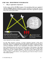
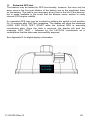
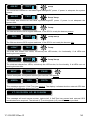
1
OWNER VESSEL RADIO CALL SIGN UIN # CAUTION: Before proceeding to install, test or use your new ACR Electronics’ product, please read this Product Support Manual in its entirety. If you have questions regarding the contents of the manual, please contact our Technical Service Department at ACR Electronics, Inc., Telephone +1 (954) 981- 3333. Please be ready to provide the technician with the page number you wish to discuss. If you have a question that is not covered in the manual, please visit our website and access the Frequently Asked Questions (FAQs) section for further information or call our Technical Service Department. The website address is www.acrelectronics.com. If in the future you lose this manual, you may access and print a replacement on the ACR website. NOTE re: Applicable products This manual supports all configurations of GlobalFix™ iPRO/ RLB-36 beacons. In addition to the part numbers listed on the cover page, other configurations of these products are available, thus you may have purchased a product configuration with a somewhat different part number. As long as the first four digits are the same as one of the two part numbers on the cover, this manual is applicable. Y1-03-0233 Rev. D 1 Table of Contents STEP ONE - REGISTERING YOUR BEACON ___________________________________ 2 STEP TWO - HOW THE BEACON WORKS ____________________________________ 6 STEP THREE - INSTALLING THE BEACON ___________________________________ 16 STEP FOUR - MAINTAINING THE BEACON __________________________________ 21 APPENDIX A - USING AND TESTING THE GPS SYSTEMS ________________________ 27 APPENDIX B - USER INTERFACE: SPECIAL ICONS ______________________________ 29 APPENDIX C - USER INTERFACE: DIGITAL DISPLAY DURING OPERATION ___________ 30 APPENDIX D - USER INTERFACE: DIGITAL DISPLAY DURING SELF-TEST ____________ 33 APPENDIX E - USER INTERFACE: DIGITAL DISPLAY DURING EXTENDED GPS TEST____ 36 APPENDIX F- USER INTERFACE: LANGUAGE TRANSLATIONS ____________________ 37 APPENDIX G - THE COSPAS-SARSAT SYSTEM ________________________________ 38 APPENDIX H - TECHNICAL SPECIFICATIONS _________________________________ 39 APPENDIX I - WARRANTY, USEFUL LIFE POLICY, NOTICES ______________________ 40 PLEASE READ ALL WARNINGS, CAUTIONS AND NOTES CAREFULLY Y1-03-0233 Rev. D 2 STEP ONE - REGISTERING YOUR BEACON 1. Why is registration important? As the owner of this 406 MHz beacon, it is mandatory that you register it with the EPIRB national authority of your country: It is the law. Please note that all 406 MHz beacons are required to have their registration updated every two years by the owner. Your unique ID code programmed inside each EPIRB is transmitted to Search and Rescue (SAR). SAR forces use this code to pull up your registration to find out valuable information about who needs help. YOUR RESCUE WILL BE DELAYED IF YOUR BEACON ISN’T PROPERLY REGISTERED! HOW REGISTRATION WORKS: All 406 MHz beacons transmit a Unique Identifier Number (UIN) when activated. This UIN is programmed into the beacon based on the country in which the beacon is registered, thus authorities are able to determine which country’s database will have your registration information. SAR forces will have information as to who you are as the owner of the beacon, the name and type of vessel that you have, your homeport, and who to contact that might know of your current situation - but only if your beacon has been properly registered. Valuable search and rescue resources are wasted every year responding to false alarms, and registering your beacon helps to resolve false alarms quickly. Y1-03-0233 Rev. D 3 2. What country should I register in? Register your beacon with the EPIRB national authority of the country for which the beacon was programmed, typically the country where purchased, regardless of where you do your boating. The beacon must be reprogrammed if you, as the owner, move or the vessel sails under the flag of a different country than the one for which the beacon was previously programmed. To verify the country for which a beacon is programmed, see the label with the UIN (Unique Identification Number) on the back of the unit. Units that do not have a country specified on the UIN label are programmed for the United States. 3. How do I register? Registration in the United States The national authority that accepts registrations in the United States is the National Oceanic and Atmospheric Administration (NOAA). Here are three ways to register: 1. The fastest and easiest way to register is online at www.beaconregistration.noaa.gov/. 2. Faxing a registration is also acceptable. Fax the registration form to the fax number on the top of the registration form. NOTE: Do not confuse the registration form with the ACR Electronics warranty card. 3. If online or fax registration is not available, mail the registration form with the pre-addressed, postage paid envelope to: NOAA SARSAT Beacon Registration NSOF, E/SP3 4231 Suitland Road Suitland, MD 20746 All registration forms will be entered in the 406 MHz beacon registration database within 48 hours of receipt. The information you provide on the registration form is used for rescue purposes only. A confirmation letter, a copy of the actual registration and a proof-ofregistration decal will be mailed to you within two weeks. When you receive these documents, please check the information carefully with the existing label on the unit, and then affix the decal to your beacon in the area marked “BEACON DECAL HERE.” If you do not receive confirmation back from NOAA in the expected timeframe, call toll free (888) 212-7283 for assistance. Y1-03-0233 Rev. D 4 Registration outside of the United States In countries other than the United States, 406 MHz beacons are registered with that country’s national authority at the time of purchase. The sales agent should have assisted you in filling out the forms and sending them to the country’s national authority. Alternatively, many countries allow online registration in the International 406 MHz Beacon Registration Database (IBRD) at www.406registration.com. To verify that the unit is properly programmed for your country, view the UIN label on the back of the unit. In the event that the beacon is not programmed for your country, the sales agent (if properly equipped) can reprogram the unit for the correct country. 4. Do I need a radio license? In the United States, you may or may not need to obtain or update a radio station license. Check the FCC’s website at http://wireless.fcc.gov/services/index.htm?job=licensing&id=ship_stations or call toll-free (888) 225-5322 (CALLFCC) for the latest information. Outside of the United States, contact your local authority for the requirements. Y1-03-0233 Rev. D 5 STEP TWO - HOW THE BEACON WORKS 1. How your beacon brings help 406 MHz beacons are a type of portable emergency equipment that transmits a distress signal to search and rescue (SAR) organizations. The purpose of these beacons is to aid SAR teams in tracking and locating ships or individuals in jeopardy as rapidly as possible. The 406 MHz frequency is a worldwide dedicated emergency frequency that is detected by a special system of satellites called the Cospas-Sarsat system. This satellite system was established by, and continues to be supported by, its primary benefactors - the USA, Russia, Canada and France. The CospasSarsat system has saved over 23,500 lives - and counting - since its inception. See Appendix G or the Cospas-Sarsat website for more information about the system at www.cospas-sarsat.org. When a 406 MHz beacon is activated, the digital distress message is sent to Cospas-Sarsat satellites and, in turn, the distress message is relayed to SAR. The distress message contains important information about the beacon and its owner. Additional information about the beacon is accessed by SAR from the beacon registration database. At the same time the 406 MHz signal is activated, a 121.5 MHz signal is turned on. The 121.5 MHz signal is used by SAR to home in on the beacon as they approach it. The 406 MHz signal is detected by multiple satellites and from that information the location of the beacon can be calculated. This data alone is sufficient for SAR to find persons or ships in distress in a reasonable timeframe. However, as a further enhancement, some beacons have a GPS engine onboard. This feature allows the beacon to acquire current location coordinates from an internal GPS receiver or download coordinates from an external GPS receiver. The coordinates are added to the ID of the unit, which is transmitted with the 406 signal. This enables the SAR authorities to locate the beacon to an accuracy of 110 yards (100 m). Y1-03-0233 Rev. D 6 2. Anatomy of your beacon NOTE: When unpacking your beacon, it is recommended that you save the original packaging for re-use when shipping the beacon for battery replacement in the future. // Activation switch with Witness Tab The activation switch embodies a special, patented method of activating a beacon. Refer to a subsequent section of this manual for how to activate the beacon. // External GPS interface The external GPS interface serves as the connection to the ship’s GPS system. // Internal GPS engine The internal GPS engine is located where it can most readily get a clear view of the sky. Y1-03-0233 Rev. D 7 Strobes Antenna Top View GPS Interface Activation/Test Switch Green LED Red LED Digital Display Screen Internal GPS Receiver Switch Positions TEST Position OFF/READY Position Y1-03-0233 Rev. D ON/TRANSMITTING Position 8 Category 1 – SeaShelter™3 Bracket HydroFix™ Hydrostatic Release Unit (HRU) Spring Release knob Ejector spring Antenna hook GPS Interface Cable Front cover hook (detent) Category 2 – LowPro™3 Bracket Water Sensor Deactivation Magnet Antenna hook GPS Interface Stowage Port Front Cover Release Tabs Release Latch Y1-03-0233 Rev. D 9 3. Digital Display The digital display in the beacon is used as a secondary visual aid, supporting the green/red LED and the audio tone, which indicate the status of the beacon during testing and during emergency operation. The messages on the digital display typically appear as one or two words at a time, until the entire message has been displayed. When the beacon is activated, the display will show the message EPIRB ON. The beacon will begin to send 406 MHz emergency signal bursts, at which time the display provides other messages including 406 SENT, 121.5 ON and GPS coordinates, provided the data was acquired. If GPS data has not been successfully downloaded into the beacon, the digital display will give you tips like “GIVE CLEAR VIEW TO SKY.” GPS √ In Self-Test, the display illustrates the test result of each step with “√” indicating a pass and “X” indicating a failure. There are a total of five tests, plus a battery check. If all tests pass, SELF-TEST PASS will be displayed at the end of the Self-Test mode. This will be followed by the GPS coordinates horizontally scrolling through the display, provided the beacon has successfully downloaded an external GPS location. See Appendixes B through E for details about display messages. EPIRB ON Language translations of the digital display messages are available from your local Battery Replacement Center (BRC). The messages can be converted to French, Spanish, German and Italian. See Appendix F for a list of messages by language. Y1-03-0233 Rev. D 10 4. Activating your beacon WARNING: This transmitter is authorized for use only during situations of grave and imminent danger. Deliberate misuse may incur a severe penalty. Overview Category I beacons are designed to be automatically deployed and activated in the event of a sinking vessel. The beacon may also be hand held on the deck of vessels, or floated in water and attached to a raft or life vest with the lanyard provided. Category II beacons are designed to be manually deployed from the bracket. Two conditions must be met for a Category II beacon to automatically activate: // It must be out of its bracket // It must be wet NOTE: Either condition by itself will not automatically activate the beacon. Category I and II beacons can always be manually activated in or out of their bracket. The beacon and bracket are designed to allow the user to perform periodic testing while the beacon is in its bracket. Y1-03-0233 Rev. D 11 Category I beacons-Automatic deployment and activation If the vessel sinks, the HydroFix™ HRU frees the beacon from the bracket, allowing it to float to the surface. Built-in sensors detect that the beacon is no longer in its bracket and when continuity is created by water between two of the top cap screws, an activation circuit is completed. NOTE: Transmission of the 121.5 MHz and 406 MHz signals will not occur until 100 seconds after activation. HRU releases the rod separating the front and back cover of bracket at a depth between 4-13 feet Y1-03-0233 Rev. D Ejector Spring launches EPIRB from the bracket allowing it to float freely to the water surface 12 Category I and II Beacons-Manual deployment and activation Both Category I and II beacons can be manually deployed by removing the beacon from the bracket. Once removed, the beacon can be activated by placing it in water OR by lifting the Activation Switch to a vertical position, sliding it toward the antenna and pushing down to the opposite side of the beacon. Activating the beacon in this manner breaks off the Activation Witness Tab and allows the switch to properly seat, showing the “ ▌ “ symbol (ON). A Category I or II beacon MANUALLY activates with the following sequence: 1.) Remove the beacon from its bracket 2.) Activation method one: Place beacon in water 3.) Activation method two: // Lift the switch to a vertical position // Slide the switch toward the antenna // Push the switch down to the opposite side of the beacon (see illustration below) Category I and II Beacons-Manual Activation Without Deployment The beacon can be manually activated while still in its bracket by placing the Activation Switch in the ON position. Activation by this method overrides all sensors and turns the beacon “ON.” Push the main switch up 90 degrees, slide toward antenna and all the way down to activate. Y1-03-0233 Rev. D Witness tab will break once placed in the “ON” position 13 TIPS FOR OPTIMUM DEPLOYMENT OF AN ACTIVATED BEACON: When activating and deploying your beacon in an emergency, DO NOT: // Hold or clutch the beacon or antenna // Operate the beacon while hand held, if at all possible // Turn the beacon off for any reason, including to save power // Activate the beacon if you have any other means of self rescue // Operate the beacon inside a life raft or under any other canopy or cover // Tether the beacon to the bracket or vessel When activating and deploying your beacon in an emergency, DO: // Follow the steps to activate the beacon as described on the beacon or in this manual // Give clear view to the sky for best GPS performance // Take the EPIRB with you if abandoning ship, provided there is time to get it // Tether beacon, using the lanyard, to the life raft and let the beacon float (if in a life raft) // Keep EPIRB upright for best signal transmission, either by floating it, resting it or holding it in this position // Manually activate the beacon if it has not been automatically activated 5. Turning off the beacon If your beacon was manually activated and you wish to deactivate, return the thumb switch to the “OFF” position. If automatically activated and you wish to deactivate, remove the beacon from the water and dry the unit or place the beacon back into the release bracket. The beacon normally takes up to 12 seconds to deactivate. If deactivation should fail, remove the four screws holding the unit together and unplug the battery to disable the unit. Return the beacon to ACR Electronics for service. 6. False alarms To prevent false alarms, it is important to be aware of how your beacon can be activated. An ACR 406 MHz EPIRB can be activated by two different methods. Whether you have a Category I or Category II, these methods are the same. // When the beacon is out of its bracket and wet, the unit will start transmitting // When the switch is moved to the “ON” position, in or out of the bracket, the unit will start transmitting Y1-03-0233 Rev. D 14 // // // // Precautions to prevent false alarms Do not mount or transport the beacon within 4.6ft/1.4m of a magnetic source. Do not store the beacon outside of its bracket if it can get wet. Do not mount the EPIRB backwards in its bracket (lanyard roll must face in). Do not clean the beacon with a water hose and brush while out of its bracket. Reporting Should there be, for any reason, an inadvertent activation or false alarm, it must be reported to the nearest search and rescue authorities. The information that should be reported includes: // The EPIRB 15-digit Unique Identifier Number (UIN) // Time and date // Duration and cause of activation // Location of beacon at the time of activation To report false alarms in the United States, contact any of the following: US Region Telephone Number Atlantic Ocean / Gulf of Mexico USCG Atlantic Area Command Center (757) 398-6390 Pacific Ocean Area / USCG Area Command Center (510) 437-3700 USCG HQ Command Center (800) 323-7233 To report false alarms outside of the USA, contact the national authority where your beacon is registered. Y1-03-0233 Rev. D 15 STEP THREE - INSTALLING THE BEACON 1. Marking battery and Hydrostatic Release Unit expiration dates NOTE: It is the beacon owner’s responsibility to record the expiration dates for both the beacon battery and the HydroFix™ hydrostatic release unit. This information must appear on the product itself. The left side of the battery housing indicates the battery expiry date. Space is provided for the beacon owner to mark the date the beacon was placed into service. The beacon should be serviced 5 years from the installation date but no later than the battery expiry date. The ACR HydroFix™ HRU has an expiration date of 2 years from the date of installation or 4 years from the date manufactured, whichever comes first. Upon installing your beacon or new HRU, permanently scratch the new expiration date on the HRU date calendar as seen below. Date of Installation Example: Date of installation of New HRU or First Installation of EPIRB including new HRU: August 1, 2009. This unit will need to be replaced in August of 2011. Scratch off “AUG 8” and “2011” on the HRU date calendar Date of Manufacture Example: On the bottom of the HRU a date of manufacture is pin stamped: 0808. This unit will need to be replaced in August 2012. Scratch off “AUG 8” and “2012” on the HRU date calendar 2. Mounting location The selection of a mounting location will vary from vessel to vessel. Beacons should be protected from outside influences while being readily accessible at all times in the event of an emergency. The location selected must be sufficiently rigid to support the weight of the total installation. Hazards to avoid when selecting a mounting location: // Vibration // Exposure to the elements // Possibility of impact from hatches, gear, or personnel // Harmful vapors // Exhaust // Harsh chemicals // Locations that can be obscured by foreign articles on a temporary or permanent basis. Y1-03-0233 Rev. D 16 CAUTION: Category I brackets must be mounted free from obstruction to allow the beacon to automatically float free from the vessel in case of sinking. The SeaShelter3™ can be mounted on a vertical surface with the beacon antenna pointing skyward or a horizontal surface with the beacon face up. Avoid mounting locations that subject the bracket to breaking waves. Avoid structures like dodgers or cabin tops that could trap the beacon upon deployment. CAUTION: Category II brackets must be mounted in a protected location that is easily accessible should it be necessary to abandon ship. The LowPro3™ can be mounted on a vertical surface with the beacon antenna pointing skyward or a horizontal surface with the beacon face up. Avoid mounting locations that subject the bracket to breaking waves. Avoid mounting locations that do not provide protection from harmful UV rays of the sun. The bracket must be mounted facing inboard to avoid being lost overboard due to impacts of breaking waves, personnel or loose gear. Visually inspect the area surrounding the mounting bracket installation site for hidden hazards or obstacles that may have been overlooked during the location selection. If there is any doubt as to the ready accessibility to the beacon at all times or if any condition may appear to be questionable, conduct a complete and thorough investigation before final approval of the installation. NOTE: When selecting the beacon bracket location, be sure to consider the requirement for four screw holes to secure the bracket, plus one hole for the NMEA cable for connection between an external GPS and the beacon, if connecting the beacon to an external GPS receiver. Y1-03-0233 Rev. D 17 CAUTION: Keep this beacon a safe distance away from all magnetic sources. Magnet safe distance is 4.6ft. or 1.4m, including the distance from stereo speakers. 3. Category I bracket The SeaShelter3™ Category I bracket has five pre-drilled screw holes to use for securing the bracket to a flat surface. Remove the SeaShelter 3™ lid by turning the spring loaded knob on the lid 1/4 turn counterclockwise and pull. The lid will lift away from the top of the base and disengage at the bottom of the base. The lid is tethered to the base to help prevent loss. Pull the beacon with steady pressure from the bracket. It is not necessary to remove the HydroFix™ Hydrostatic Release Unit (HRU) to mount the bracket using four of the holes. For extreme conditions a fifth hole is available when the HydroFix is removed and the ejector spring is deployed. The bracket can be held in place to mark the placement of the screw holes or you can use the mounting template provided. The use of #10 pan head stainless steel fasteners (minimum of ½” long) and ½” washers (not included) is recommended. Make sure that fasteners will not contact any wires or plumbing before drilling pilot holes. Y1-03-0233 Rev. D 18 4. Category II bracket Category II brackets are designed to hold the beacon securely in place. The beacon must be manually deployed. The bracket can be mounted on a vertical flat surface with beacon antenna up or on a horizontal flat surface facing skyward. This location must be easily accessible in order to manually deploy the beacon or to perform the required maintenance and functionality tests. Typical locations include near the helm station or just inside the companionway door. The LowPro3™ Category II bracket has four pre-drilled screw holes to use for securing the bracket to a flat surface. Remove the beacon from the bracket. To do this while holding the assembly, lift the latch to release bracket pressure from the beacon. The beacon will slide up and out of the bracket. On either side of the bracket are release tabs. Simultaneously depress each tab to separate the bracket from the mounting block. The mounting block can be held in place to mark the placement of the screw holes or you can use the mounting template provided. The use of #8 pan head stainless steel fasteners and washers (not included) is recommended. Be sure to confirm that fasteners will not contact any wires or plumbing before drilling pilot holes. Mounted to wall LATCH OPEN Y1-03-0233 Rev. D LATCH CLOSED 19 5. Installing the optical interface to an external GPS receiver The beacon is fitted with an optical interface to connect with an external Global Positioning System (GPS) receiver that will determine the latitude and longitude of its position. The black lead wire with white stripes should be connected to the output of the external GPS receiver positive transmitter pin. The black wire should be connected to the negative pin. If you have a Category I beacon and bracket, the connector is at the end of the black lead wire plugs into the beacon via the bezel on the top of the beacon. See the location of the GPS interface in previous figures (“Anatomy of your beacon”, page 7 and “Top View”, page 8). It is important to seat the connector completely in the bezel for an operational connection. If you have a Category II beacon and bracket, your connector has two extensions on it that must be aligned with the two notches on the Category II beacon bezel. The connector is then gently inserted downward into place and turned 90° to lock the connector into the bezel. If the external GPS receiver is operational and the connection has been correctly made to the optical interface, the green LED in the optical interface will start flashing at activation. NOTE: The baud rate output for your GPS receiver NMEA 0183 should be 4800 bps. If you are not sure if your receiver is NMEA 0183 compliant, check the interface settings listed in your GPS manual. To optimize your GPS interface feature, be sure that your GPS receiver is equipped with a NMEA 0183 Version 1.5 or higher with GPGGA sentence enabled. Consult your GPS receiver manual for the maximum cable length acceptable for an external GPS connection to the beacon. Also see Appendix A for information regarding the use and testing of your GPS system in conjunction with the beacon. Using the optical interface is not necessary for the beacon to function properly; it will, however, enhance the beacon’s performance. Y1-03-0233 Rev. D 20 STEP FOUR - MAINTAINING THE BEACON 1. Safety DOs and DON’Ts On a routine basis aboard ship, DO NOT: // Hold or carry the beacon by its antenna // Mount the beacon in its bracket close to large structures or magnetic areas // Tie the lanyard to the EPIRB bracket or any other structure // Obscure the beacon by placing objects in front of it On a routine basis aboard ship, DO: // Mount the beacon in its bracket in an obvious location, so that all can see it // Mount the beacon in its bracket with the rolled lanyard facing inward (facing the bracket) // Follow the recommended maintenance schedule // Perform a beacon Self-Test monthly // Follow up with beacon service if Self-Test fails 2. Routine beacon maintenance At least every ninety days, the float free mounting bracket and beacon should be inspected for deterioration and/or residue buildup that may affect the function of the beacon or automatic release. Part of the visual check includes checking the antenna for tightness. Clean the beacon and the mounting bracket to remove any residue buildups. It is recommended that the beacon and mounting bracket be wiped with a damp cloth. Carefully inspect the beacon case for any visible cracks. Cracks may admit moisture, which could falsely activate the beacon or otherwise cause a malfunction. Any cracks observed should immediately be referred to ACR Service for evaluation. Call ACR Electronics Technical Service +1 (954) 9813333. 3. Battery replacement Battery replacement is due 5 years from date after the beacon placed into service, or by expiry date on the beacon whichever is first. During each inspection, check the time remaining until battery replacement is required. The battery must also be replaced if the beacon has been activated for any use other than the Self-Test. Y1-03-0233 Rev. D 21 Always refer battery replacement and any other beacon service to a factory authorized Service Center. Find a Center near you at http://www.acrelectronics.com/brc.htm. Battery replacement includes servicing the beacon by replacing all o-rings, testing the water seal and the electrical properties and doing a full functional test on the unit. NOTE: There are no user serviceable items inside the beacon. Do not open the beacon except to disable (in case of faulty or accidental activation). Otherwise, always have the beacon serviced. WARNING: Battery contains lithium To avoid possible fire, explosion, leakage or burn hazard, do not open, recharge, disassemble or heat beacon above +70ºC (+158ºF) or incinerate. These products contain lithium in the battery. Various beacons may or may not require special shipping instructions due to the lithium batteries and changes in shipping regulations. Shipping of hazardous materials requires special handling and documentation. MSDS sheets, along with shipping information, can be found on our website at http://www.acrelectronics.com/hazmat/default.htm. In the case of the RLB-36, the product contains small batteries that are nonhazardous. However, regulations can change. Be advised that it is best to verify the shipping requirements at the time you are preparing to ship the unit. 4. Shore based maintenance for SOLAS vessels, (SBM) IMO MSC/Circ. 1039 The Maritime Safety Committee has approved guidelines for shore-based maintenance of satellite beacons, for the purpose of establishing standardized procedures and minimum levels of service for the testing and maintenance of satellite beacons. The first shore based maintenance on all ACR EPIRBs is due at the date of the first battery replacement. Visit ACR’s website at www.acrelectronics.com for organizations that perform shore based maintenance. 5. Annual testing for SOLAS vessels, IMO MSC/Circ. 1040 SOLAS regulation IV/15.9 dictates annual testing of 406 MHz satellite EPIRBs. Testing should be carried out using suitable test equipment capable of performing the relevant measurements. All checks of electrical parameters should be performed in the self-test mode, if possible. These tests can be performed by certified ACR Battery Replacement Centers (BRCs). Visit ACR’s website at www.acrelectronics.com for authorized ACR BRCs. Y1-03-0233 Rev. D 22 6. Changing ownership or contact information As the owner of the beacon, it is your responsibility to advise the national authority of any change in the information on the registration form. If you are transferring the beacon to a new owner, you are required to inform the national authority. You can do this by using their online database or by letter, fax or telephone and informing the authority of the name and address of the new owner. The new owner of the beacon is required to provide the national authority with all of the information requested on the registration form. This obligation transfers to all subsequent owners. Registration forms for the United States are available from NOAA by calling (888) 212-7283 (212-SAVE) or by visiting the ACR website at www.acrelectronics.com. Outside of the United States, the new owner may contact his local authority for the necessary form(s). 7. Lost or stolen EPIRBs If your EPIRB is lost or stolen, do the following immediately: // Report to your local authorities that the EPIRB has been lost or stolen // Contact NOAA at (888) 212-7283 (212-SAVE), or your national authority, with the following information: o Police department name o Police department phone number o Police case number If your EPIRB were to be activated, the information you provided will be forwarded to the appropriate search and rescue authorities who will ensure that your EPIRB gets back to you. If someone attempts to register an EPIRB reported as stolen, NOAA or your national authority will notify the appropriate police department. Visit www.cospas-sarsat.org for more detailed information. 8. Servicing the SeaShelter3™ and the HydroFix™ HRU The SeaShelter3™ Category I bracket has two main pieces, the lid and the base. To open the bracket, turn the spring loaded knob counterclockwise 1/4 of a turn and pull. The lid will lift away from the top of the base and disengage from the detent at the bottom of the base. The lid is tethered to the base to help prevent loss. Brackets are a key part of the overall beacon system. They hold a beacon ready for deployment while preventing false alarms. Category I brackets also require replacement of the Hydrostatic Release Unit every two years. NOTE: Whenever a beacon is returned for service, it must be accompanied by the bracket. Y1-03-0233 Rev. D 23 To remove the expired HRU When opening the SeaShelter3™ lid, note that the beacon is installed with the lanyard face in. Pull the beacon with steady pressure from the bracket. Do not get beacon wet while out of bracket. The HRU has a keying feature that locks it to the bracket. If you view the HRU rod as the center of a clock, a properly installed HRU will rest at the 7 o’clock position, as shown in the picture above. WARNING: The HRU holds down an ejection spring. The spring must be held in place during the removal and installation of the HydroFix™ to prevent injury. Depress the top of the ejection spring. This will relieve pressure on the HRU and allow it to be rotated counterclockwise to the 5 o’clock position. The HRU is now free to be removed. Slowly relieve pressure from the ejection spring and allow it to deploy. WARNING: Discard the expired HRU. Failure to replace the entire assembly may cause the bracket to malfunction. WARNING: Be sure to use only ACR’s HydroFix™ HRU (ACR P/N 9490) in the SeaShelter3™. Use of unauthorized replacement parts will void your warranty and may cause the bracket to malfunction. Check the date of manufacture on the new HRU. Follow the instructions that accompany the HydroFix™ for marking the next expiry date and for selecting the correct rod adapter for the SeaShelter3™. To install the new HRU Apply pressure to the ejection spring and hold it flat against the bracket. With your free hand place the new HRU into the key way in the 5 o’clock position and rotate clockwise to the 7 o’clock position. Slowly remove pressure from the ejection spring. The HRU should now be held in the 7 o’clock position with the pressure on the ejection spring. Reinstall the beacon with lanyard face in. Beacon should fit snugly in the bracket with the antenna captured by the bracket. Reinstall the lid by seating the bottom of the lid to the detent on the base. Close the upper portion of the lid so the HRU rod lines up with the spring loaded knob. With gentle pressure, hold the lid while you turn the lock counterclockwise until it stops, then clockwise until it stops. This should capture the HRU and snap the lid into a locked position. Confirm that the lid is attached to the bottom of the bracket and the HRU. CAUTION: Do not force the lid closed. If the lid does not close easily, check to see that the beacon is properly installed in the bracket and the HydroFix™ is properly seated. Y1-03-0233 Rev. D 24 9. Servicing the LowPro3™ To remove a beacon from the Category II bracket, lift the latch and release the pressure from the beacon. The beacon will now be able to slide upwards out of the bracket. ™ It is not anticipated that the LowPro3 cleaning or, rarely, replacement. will require servicing other than Brackets are a key part of the overall beacon system. They hold a beacon ready for deployment while preventing false alarms. NOTE: Whenever a beacon is returned for service, it must be accompanied by the bracket. 10. Self-Testing the beacon The RLB-36 beacon may be self-tested as is warranted, up to a maximum of sixty times in the five-year life of the battery, or once per month for the life of the battery. Self-Tests can be performed randomly, however, ACR recommends that you perform the Self-Test on a once per month schedule. Do not exceed sixty (60) Self-Test cycles limit in the five-year life of the battery, to conserve the battery for emergency use. The functional Self-Test is initiated by momentarily lifting the Activation Switch to a vertical position and holding it in this position for at least one second and at most four seconds. A beep indicates the initiation of the Self-Test sequence. Self-Test will check battery capacity and perform five functional test sequences as described in the digital display Appendix. The last green LED and the message SELF-TEST PASS on the display indicate a successful test. If any of the individual tests fail during Self-Test, there will be two beeps and a red LED flash, with the name of the test that failed and an “X” on the display. Self-Test will discontinue at that point. See Appendix D for digital display information. NOTE: The “beeps” are a very high-pitched tone that some people may not be able to hear. When performing the Self-Test, you may follow the messages on the digital display or you may count the green LED flashes. Y1-03-0233 Rev. D 25 11. Extended GPS test The beacon may be tested for GPS functionality, however, this may only be done once in the five-year lifetime of the battery due to the significant drain on the battery. This test is not necessary at any time in the life of the beacon, but is made available in the event that the beacon owner wishes to verify internal GPS engine viability. An extended GPS test may be invoked by holding the switch in test position for 10 seconds after Self-Test completes. The display will show the message LONG GPS DATA TEST START while the internal GPS is acquiring coordinates data. Once the data is acquired, the display will post the message GPS TEST √ followed by the LAT/LON coordinates as a confirmation that the data was successfully acquired. See Appendix E for digital display information. 26.03.33N 80.10.06W Y1-03-0233 Rev. D 26 APPENDIX A - USING AND TESTING THE GPS SYSTEMS 1. How the external GPS interface works The beacon is fitted with an optical interface to connect with an external Global Positioning System (GPS) receiver that will determine the latitude and longitude of its position. This data is transmitted to the emergency system. When the beacon is coupled to a working external GPS receiver, it immediately begins downloading data. Once valid position data has been obtained, the beacon will attempt to update the positional data every 20 minutes. The GlobalFix™ iPRO will store the last valid positional data for up to 4 hours, if it becomes unable to obtain new updated data. It will update this data if and only if it receives new good positional data from the external GPS receiver. 2. Using the external GPS interface Once a compatible, operating GPS receiver is connected to the GlobalFix™ iPRO, the beacon will store coordinate data for incorporation into the emergency message. The coordinates are transmitted to the satellite when the beacon is activated in an emergency. Coordinate data provides a more accurate location to the Search and Rescue Authority and may lead to a faster rescue. Since the last valid GPS position data may stay in the memory for up to 4 hours, the user should take care to make sure that the GPS position data stored is accurate. This can be accomplished by two methods: // By always leaving a properly functioning external GPS receiver connected to the beacon before activation, or… // By connecting a properly functioning external GPS receiver with a valid position fix, and allowing sufficient time to acquire valid GPS position data. 3. Testing the external GPS interface Connect the optical interface plug to the beacon bezel and allow sufficient time for the GPS receiver to acquire valid GPS position data (usually less than 1 minute; but it can take up to 20 minutes). Lift the thumb switch to the vertical (Self-Test) position and release. Your beacon will confirm that it has acquired valid GPS data by displaying the latitude and longitude coordinates on the display. This will occur at the end of Self-Test. 4. Updating the external GPS position data When the beacon is properly connected to a functioning and compatible GPS receiver, GPS position data is automatically updated about every 20 minutes while valid GPS position data is present. The operator can force the acquisition of new GPS position data by initiating a Self-Test with the beacon connected to an external GPS receiver with a valid position fix. This bypasses the normal, programmed, waiting time of 20 minutes for the automatic update of GPS position data. Y1-03-0233 Rev. D 27 If the new GPS position is acquired, the coordinates will be displayed after the beacon has completed the Self-Test. If no valid GPS position data is available, the beacon will keep the previously stored GPS position data for up to 4 hours. In this case, call ACR Customer Service at +1 (954) 981-3333 for instructions on how to reset the beacon with the default message. A new beacon is programmed with the GPS position data set to a default. If the beacon should be activated, this default GPS position data indicates to the satellite system that the beacon has no valid GPS position stored in memory. Once a functioning and compatible external GPS receiver is properly connected to the beacon, the default data will be replaced by valid GPS position data, as described in the previous sections. 5. Internal GPS position system The GlobalFix™ iPRO is fitted with an internal GPS receiver that will determine the coordinates (latitude and longitude) of the beacon’s position on the globe, to be transmitted to the Cospas-Sarsat emergency system. When the beacon is turned on, the internal GPS is immediately turned on and it attempts to acquire positional coordinates. GPS coordinates can be acquired any time that the GPS is on, but only valid data is saved. Once the beacon acquires valid coordinates, the data is included as part of the next transmitted 406 MHz digital message. The internal GPS operates on a schedule during which the beacon is on for a time, actively acquiring coordinates, and off for a time, in a resting state. The schedule is designed to conserve battery but, at the same time, assure that navigational coordinates are regularly updated. 6. LED indication of GPS fix When the beacon is activated and valid coordinates are acquired, the data is included in the digital message of the next 406 MHz transmission. The LED blinks green when GPS coordinates are sent. If a time period of 4 hours passes without the internal GPS receiver being able to update the last good set of navigational coordinates, the message transmitted by the beacon will revert back to default data. At this point the green LED will stop blinking and the red LED will flash. The internal GPS will continue to seek coordinates and when successful the green LED will flash. This new data will be transmitted in the next message burst and the green LED will continue to flash. Y1-03-0233 Rev. D 28 7. Compatible GPS receivers External GPS interface requirements: In order to be compatible with the GlobalFix™ iPRO, an external GPS receiver must provide location information according to the following requirements: // // // // NMEA 0183, Version 1.5 or higher Baud rate: 4800 Talker device identifier: GP (GPS Receiver) Sentence format: GGA (GPS Fix Data) For more information regarding external GPS device compatibility, please visit the ACR website at www.acrelectronics.com. APPENDIX B - USER INTERFACE: SPECIAL ICONS Characters displayed during beacon operation include the following: The battery gauge appears on certain screens to indicate the remaining level of battery charge The gauge illustrates the remaining charge in the battery as a percent of the total possible charge, e.g., The gauge will show the system to be charged in the following increments: 100, 75, 50 and 25%. The frequency transmission symbol appears on certain screens to indicate that the transmission has been sent G R The symbols for a green or a red LED light, respectively Indicates scrolling text Y1-03-0233 Rev. D 29 APPENDIX C - USER INTERFACE: DIGITAL DISPLAY DURING OPERATION The following chart describes the audio-visual feedback the beacon provides during activation. The messages on the digital display typically appear as one or two words at a time, until the entire message has been displayed. GlobalFix™ iPRO Display, LED/ Audio Signaling and Description of Operation R R long beep The beacon has been activated and the ACR Electronics Welcome Page appears Next, the product name appears EPIRB ON The system reports that the beacon is on and in activation mode GPS ON The system reports that the beacon has turned on the GPS engine GIVE CLEAR VIEW TO SKY The system reminds you that for optimum GPS performance, i.e., greatest likelihood of acquiring coordinates, position the beacon so that it has a clear view of the sky. DO HOLD NOT AERIAL The system reminds you that for optimum transmission of the emergency message, allow the beacon to float and do not hold the antenna (aerial). 406 SENT G R beep The system reports that the 406 MHz emergency message has been sent. If this message accompanied by a green LED flash, the GPS coordinates have been sent as well. If accompanied by a red LED flash, the GPS coordinates have not been sent. NOTE: If GPS coordinates were not sent, the system will continue to attempt to acquire the data and add it to the 406 MHz distress signal when available. Updated GPS coordinates are sent every twenty minutes. GPS SENT G This message appears only if GPS data was acquired Y1-03-0233 Rev. D 30 121.5 ON G R The system reports that the 121.5 MHz homing signal is on. Search and Rescue (SAR) personnel use this frequency when arriving close to the scene. If this message is accompanied by a green LED flash, the GPS coordinates have been sent. If accompanied by a red LED flash, the GPS coordinates have not been sent. NOTE: If GPS coordinates were not sent, the system will continue to attempt to acquire the data and add it to the 406 MHz distress signal when available. Updated GPS coordinates are sent every twenty minutes. GPS DATA XX.XXX’ G The system reports recently acquired GPS coordinates. You may be able to communicate the coordinates to SAR or other persons assisting in the rescue. The green LED flash indicates that GPS coordinates have been sent. Coordinates will scroll from right to left with the following information: LT: XXº XX.XX’,N and LG: XXXº XX.XX’,W GPS WEAK GIVE CLEAR VIEW TO SKY R The system alerts you that the GPS coordinates have not been acquired and therefore have not been sent. The system reminds you that GPS data acquisition is optimized by giving the beacon a clear view of the sky. Y1-03-0233 Rev. D 31 LEAVE G EPIRB ON UNTIL RES Q R The system reminds you that leaving the beacon on continuously gives the best assurance of being rescued. SAR groups need the ongoing transmissions from the beacon to most effectively find you. If this message is accompanied by a green LED flash, the GPS coordinates have been sent. If accompanied by a red LED flash, the GPS coordinates have not been sent. NOTE: If GPS coordinates were not sent, the system will continue to attempt to acquire the data and add it to the 406 MHz distress signal when available. Updated GPS coordinates are sent every twenty minutes. KEEP EPIRB UP RIGHT G The system reminds you that optimum performance of the beacon is achieved when the system is floating and/or kept upright. Y1-03-0233 Rev. D 32 APPENDIX D - USER INTERFACE: DIGITAL DISPLAY DURING SELF-TEST The following chart describes the display and audio-visual feedback the beacon provides during Self-Test. The messages on the digital display typically appear as one or two words at a time, until the entire message has been displayed. GlobalFix™ iPRO Display, LED/ Audio Signaling and Description of Operation Beacon Self-Test has been initiated, and the ACR Electronics’ Welcome Page appears. Next, the product name page appears. BATT > 48HR √ G beep The first test checks the available hours of battery life (battery witness seal). If remaining battery life is greater than 48 hours at -20° C, the test passes. BATT > 48HR R beep beep The first test checks the available hours of battery life (battery witness seal). If remaining battery life is less than 48 hours at -20° C, the test fails. MEM √ G beep The second test checks the beacon message for absence of errors (EEPROM memory). If no errors are present the test passes. MEM R beep beep The second test checks the beacon message for absence of errors (EEPROM memory). If an error(s) is present, the test fails. BOARD TEST √ beep G The third test checks circuit board (lock circuit) functionality. If the board is performing properly, the board passes. BOARD TEST R beep beep The third test checks circuit board (lock circuit) functionality. If the board is not performing properly, the board fails. Y1-03-0233 Rev. D 33 406 RF TEST √ G beep The fourth test checks for 406 MHz signal strength/RF power. If power is adequate the system passes. 406 RF TEST R beep beep The fourth test checks for 406 MHz signal strength/RF power. If power is not adequate the system fails. GPS TEST √ G beep The fifth test checks GPS engine readiness. If the GPS is ready the beacon passes. GPS TEST R beep beep The fifth test checks GPS engine readiness. If the GPS is not ready the beacon fails. LIGHT TEST √ G beep The sixth test checks four LEDs, collectively the LED strobe, for functionality. If all LEDs are working the test passes. LIGHT TEST R beep beep The sixth test checks four LEDs, collectively the LED strobe, for functionality. If all LEDs are not working the test fails. SELF TEST PASS G If all six tests pass, the system advises you that Self-Test passed. NMEA GPS DATA This message appears if Self-Test has passed. The display indicates that the external GPS has updated its coordinates during Self-Test. LT: 26.03.033N LG: 80.10.066W This message will scroll across screen, right-to-left, if Self-Test has passed and external GPS coordinates were acquired. The latitude (LT) and longitude (LG) coordinates are provided. Y1-03-0233 Rev. D 34 NO NMEA GPS DATA This message appears if Self-Test has passed. The display indicates that the external GPS did not update its coordinates during Self-Test. NOTE: If external GPS data cannot be acquired, typically due to the external GPS not having achieved a good fix, it does not affect the pass status of Self-Test. Self-Test requires GPS engine readiness but does not require that the GPS obtain coordinates. SELF TEST FAIL R long beep If one of the six tests fails, the system advises you that Self-Test has failed. SEE USER BOOK This message appears if Self-Test failed. The system advises you to refer to this Product Support Manual (User Book) for information on what to do and who to contact. SEEK FIX NOW This message appears if Self-Test failed. The system advises you to seek service from an authorized Service Center. Not only should the beacon be fixed immediately, it also should not be placed into service until the problem is addressed. NOTE: “SEEK FIX NOW” has the same meaning as “FIX NOW” BATT LOW This message appears if Self-Test has passed, but the battery is low. Take the beacon to an authorized Service Center for a battery replacement. NOTES regarding Self-Test logic: 1.) When one of the tests fail, the system bypasses the remaining tests and goes to SELF-TEST FAIL 2.) The only exception to #1 is that if the battery fails, the other tests are still performed. The system will tell the user if there are other system failures by flashing SELF-TEST FAIL. If there are no failures other than battery life, the system flashes SELF-TEST PASS, then BATT LOW. Y1-03-0233 Rev. D 35 APPENDIX E - USER INTERFACE: DIGITAL DISPLAY DURING EXTENDED GPS TEST The following chart describes the display and audio-visual feedback the beacon provides during extended GPS Test. The messages on the digital display typically appear as one or two words at a time, until the entire message has been displayed. GlobalFix™ iPRO display, LED/ Audio Signaling and Description of Operation LONG GPS DATA TEST START The system informs you that the extended GPS test has initiated. GIVE CLEAR VIEW TO SKY The system reminds you that GPS data acquisition is optimized by giving the beacon a clear view of the sky. GPS TEST The system informs you that the beacon is in the process of performing the extended GPS test. This message repeats for approximately 100 seconds while the GPS is acquiring data. GPS TEST √ G long beep The system informs you that the beacon has passed the extended GPS test. NMEA GPS DATA This message appears if the extended GPS test has passed. The display indicates that the external GPS has updated its coordinates. LT: 26.03.033N LG: 80.10.066W The system provides the user with the GPS coordinates acquired during a successful test. Coordinates will scroll from right-to left. NO GPS R long beep The system informs you that the beacon has failed the extended GPS test after 10 minutes. SEE USER BOOK This message appears if extended GPS test failed. The system advises you to refer to this Product Support Manual (User Book) for information on what to do and who to contact. TEST END The system informs you that the extended test is complete, and that the system is entering shut down. Y1-03-0233 Rev. D 36 APPENDIX F- USER INTERFACE: LANGUAGE TRANSLATIONS The RLB-36 user interface is available in five languages: English, French, Italian, Spanish and German. The following table provides the digital display phrases that appear on the screen. Please note that all language translations utilize simple terms and abbreviations for the purpose of speed and readability of messages. English phrases EPIRB ON GPS ON GIVE CLEAR VIEW TO SKY DO NOT HOLD AERIAL* 406 SENT GPS SENT 121.5 ON GPS DATA GPS WEAK LEAVE EPIRB ON UNTIL RES Q French Spanish German Italian RLS ON GPS ON CLAIR VUE DU CIEL NE PAS TENIR ANTEN 406 EMIS GPS EMIS 121.5 ON DATA GPS GPS FAIBL GARDE RLS ACTIF JUSQU AIDES ARRIV TENIR RLS VERT. RDBLZ ON GPS ON PON A CIELO ABIER. NO TOQUE LA ANT. 406 ENVÍO GPS ENVÍO 121.5 FREQ. DATOS GPS GPS DÉBIL DEJA RDBLZ ON HASTA RESCA. TEN LA RDBLZ RECTA BAT >48 HR MEMO CIRCU TEST FREQ. 406 MHZ TEST GPS TEST LUZ TEST TEST OK EPIRB AN GPS AN FREIE SICHT NACH OBEN. ANT NICHT FESTH 406 TX GPS TX 121.5 EIN GPS DATEN GPS LOW EPIRB AN BIS HILFE EPIRB ON GPS ON PUNTA AL CIELO NON TOCCA ANTEN. 406 EMESS. GPS EMESS. 121 ON DATI GPS GPS DEBOL. LASCI EPIRB ON EPIRB AUFR. HALT. TENGA DRITO. BATT >48H MEM BOARD TEST 406RF TEST BATT >48HR MEM BOARD TEST 406RF TEST GPS TEST LICHT TEST EIGEN TEST OK NMEA GPS DATEN KEINE NMEA GPS DATEN EIGEN TEST FEHL. S. HANDB GPS TEST LUCE TEST SELF TEST PASS DATI GPS NMEA NO DATI GPS NMEA AUTO TEST NO-OK VEDI LIBRO UTENT. CERCO SERV. BATT >48HR MEM BOARD TEST 406RF TEST BATT >48HR MEM PANAU TEST 406RF TEST GPS TEST LIGHT TEST SELF TEST PASS NMEA GPS DATA NO NMEA GPS DATA SELF TEST FAIL SEE USER BOOK SEEK FIX NOW FIX NOW GPS TEST LAMPE TEST AUTO TEST PASSE DATA NMEA GPS KEEP EPIRB UP RIGHT ECHEC AUTO TEST VOIR GUIDE UTIL DMD REPAR URGT REPAR URGT BATT LOW LONG GPS DATA TEST START NO GPS TEST END BATT FAIBL DEBUT TEST LONG GPS DATA PAS DE GPS FIN DE TEST Y1-03-0233 Rev. D DATOS NMEA GPS NO DATOS NMEA GPS FALLO TEST VEA LIBRO USO BUSCA. SERV. AHORA SERV. AHORA BAT BAJA INIC. TEST DE DATOS GPS NO GPS FIN TEST SUCHE ENDE JETZT SAT FIX BATT LEER START DES LANG. GPS DAT. TEST KEIN GPS TEST ENDE CERCO SERV. BATT SCARC. TEST GPS LUNGO NO GPS TEST END 37 APPENDIX G - THE COSPAS-SARSAT SYSTEM 1. General overview EPIRBs transmit to the satellite portion of the Cospas-Sarsat system. Cospas-Sarast satellites are an international system that utilizes Russian Federation and United States’ low altitude, near-polar orbiting satellites (LEOSAR). These satellites assist in detecting and locating activated 406 MHz satellite beacons. Cospas-Sarsat satellites receive distress signals from EPIRBs transmitting on the frequency of 406 MHz. The Cospas-Sarsat 406 MHz beacon signal consists of a transmission of nonmodulated carriers followed by a digital message format that provides identification data. The 406 MHz system uses satellite-borne equipment to measure and store the Doppler-shifted frequency along with the beacon’s digital data message and time of measurement. This information is transmitted in real time to an earth station called the Local User Terminal (LUT), which may be within the view of the satellite, as well as being stored for later transmission to other LUTs. The LUT processes the Doppler-shifted signal from the LEOSAR and determines the location of the beacon, then the LUT relays the position of the distress to a Mission Control Center (MCC) where the distress alert and location information is immediately forwarded to an appropriate Rescue Coordination Center (RCC). The RCC dispatches Search and Rescue (SAR) forces. The addition of the GEOSAR satellite system greatly improves the reaction time for a SAR event. This satellite system has no Doppler capabilities at 406 MHz, but will relay the distress alert to any of the LUT stations. When there is GPS data included in the distress message, SAR authorities instantly know your location to within 110 yards (100 m). This speeds up the reaction time by not having to wait for one of the LEOSAR satellite to pass overhead. Because most of the search and rescue forces presently are not equipped to home in on the 406 MHz Satellite beacons signal, homing must be accomplished at 121.5 MHz. Once the 406 MHz signal is relayed through the LEOSAR and/or GEOSAR network, SAR forces determine who is closest, and then proceed to the beacon using the 121.5 MHz homing frequency. 2. Global Positioning System (GPS) The GPS system is a satellite group that enables a GPS receiver to determine its exact position to within 30 m (100 ft.) anywhere on earth. With a minimum of 24 GPS satellites orbiting the earth at an altitude of approximately 11,000 miles they provide users with accurate information on position, velocity, and time anywhere in the world and in all weather conditions. The GlobalFix™ iPRO stores adds this data to its distress transmission, allowing search and rescue forces to narrow the search to a very small area, thus minimizing the resources required, and dramatically increasing the effectiveness of the overall operation. Y1-03-0233 Rev. D 38 APPENDIX H - TECHNICAL SPECIFICATIONS GENERAL/ ENVIRONMENTAL Beacon size (without antenna) 17.7 H X 10.67 W X 9.09 D cm (6.97 X 4.2 X 3.58 in) Display size 2.54 cm (1.0 in) diagonal Beacon weight 581 g (20.49 oz) Beacon material High impact UV resistant polymer Color ACR-Treuse™ (high visibility yellow) Waterproof Tested to 10 min @10 m (33 ft), exceeds RTCM standard Buoyant Yes Deployment Category I: Automatic hydrostatic release Category II: Manual BATTERY Operational life 48 hours minimum @-20ºC (-4ºF) (Class 2) Battery type and LiMnO2 replacement interval 5 years from date beacon placed in service, or after use in an emergency not to exceed battery expiry Operating temperatures -20º C to +55º C (-4º F to +131º F) (Class 2) Storage temperatures -30º C to +70º C (-22º F to +158º F) (Class 2) 406 MHz TRANSMITTER Frequency 406.037 MHz Power output 5W Digital message format Standard location protocol (for the USA; Beacon can be reprogrammed at a service center to other coded formats, and to national location protocol) 121.5 MHz TRANSMITTER Frequency 121.5 MHz Power output 25 mW PEP Modulation type AM (3K20A3X) LED STROBE Light color White Output power 1 cd (effective candela) Flash rate 20-30/ min Range 360º visibility GENERAL Accessories SeaShelter3™ Category I Mounting bracket, ACR P/N 9501 LowPro3™ Category II Mounting bracket, ACR P/N 9502 HydroFix™ universal hydrostatic release (HRU) kit, ACR P/N 9490 Approvals FCC ID #B66ACR-RLB36 COSPAS-SARSAT certificate #189 USCG #161.011/86/0 MED EC Type Examination (Module B) Certificate No.: BSH/4612/5060959/08 NOTE: For complete information regarding beacon type approvals, please visit ACR’s website at www.acrelectronics.com Y1-03-0233 Rev. D 39 APPENDIX I - WARRANTY, USEFUL LIFE POLICY, NOTICES 1. Limited Warranty This product is warranted against factory defects in material and workmanship for a period of 1 (one) year* from date of purchase or receipt as a gift. During the warranty period ACR Electronics, Inc. will repair or, at its option, replace the unit at no cost to you for labor, materials and return transportation from ACR. For further assistance, please contact our Technical Service Department at ACR Electronics, Inc., 5757 Ravenswood Road, Fort Lauderdale, FL 33312-6645. Email: [email protected], Fax: +1 (954) 983-5087, Telephone: +1 (954) 9813333. This warranty does not apply if the product has been damaged by accident or misuse, or as a result of service or modification performed by an unauthorized factory. Except as otherwise expressly stated in the previous paragraph, THE COMPANY MAKES NO REPRESENTATION OR WARRANTY OF ANY KIND, EXPRESS OR IMPLIED, AS TO MERCHANTABILITY, FITNESS FOR A PARTICULAR PURPOSE, OR ANY OTHER MATTER WITH RESPECT TO THIS PRODUCT. The Company shall not be liable for consequential or special damages. To place the warranty in effect, register online at www.acrelectronics.com or return the attached card within 10 days. *Five years for the following products: EPIRB, PLB, S-VDR, SSAS. 2. Useful Life Policy The typical service life of a properly maintained Product is limited to 12 years from date of manufacture. Products that are 12 years and 1 month or older from date of manufacture will not be serviced by ACR or our Battery Replacement Centers. A Product that is 12 or less years old from date of manufacture will be serviced as long as the unit appears fit to be placed back into its final operational cycle. Service includes the replacement of those items that must be replaced at service intervals and the verification that the device appears to be in good mechanical and electrical working condition by an ACR authorized service technician. 3. Notices ACR Electronics diligently works to provide a high quality Product Support Manual, however, despite best efforts, information is subject to change without notice, and omissions and inaccuracies are possible. ACR cannot accept liability for manual contents. To ensure that you have the most recent version of the Product Support Manual, please visit the ACR website at www.acrelectronics.com. ©2009 by ACR Electronics, Inc., part of Cobham plc. All rights reserved. Reproduction in whole or in part is permitted only with permission of ACR Electronics, Inc. Ongoing product improvements may change product specifications without notice. Trademarks or registered trademarks are the property of their respective owners. Y1-03-0233 Rev. D 40 EC DECLARATION OF CONFORMITY ACR Electronics hereby declares that the following product is in conformity with Council Directive 96/98/EC of 20 December 1996 on Marine Equipment (MED) last amended by Commission Directive 2008/67/EC of 30 June 2008, and has been type examined as described in this Declaration. In accordance with the Directive, the product will be marked with the MED Mark of Conformity as follows: 0735 yy yy = Last two digits of the year in which the mark is affixed Product: 406 MHz (COSPAS-SARSAT) Emergency Position-Indicating Radio Beacon (EPIRB) MED Item A.1/5.6 TM Trade Name: GlobalFix iPRO Model: RLB-36 Notified Body: Bundesamt für Seeschifffahrt und Hydrographie (BSH), Notified Body No. 0735 Bernhard-Nocht-Str. 78, 20359 Hamburg, Germany EC Type Examination (Module B) Certificate No.: BSH/4612/5060959/08 EC Quality System (Module D) Certificate No.: BSH/4613/05102/1251/09 Regulations and Standards: IMO Resolution A.662(16) IMO Resolution A.694(17) IMO Resolution A.696(17) IMO Resolution A.810(19) IMO MSC/Circ.862 ETSI EN 300 066 V1.3.1 (2001-01) Manufacturer: ACR Electronics Inc. 5757 Ravenswood Road Fort Lauderdale, FL 33312 USA ITU-R M.633-2 (05/00) ITU-R M.690-1 (10/95) C/S T.001 (Nov. 2007) C/S T.007 (Nov. 2007) IEC 61097-2. Ed. 3.0, 2008-01 IEC 60945, 4th Ed., 2002-08 European ACR Electronics Inc. Representative: (European Office) 1 Rose Cottages, Pitmore Lane, Sway, Lymington, Hampshire SO41 6BX UK Signed on behalf of ACR Electronics Inc. Signed: _____________________________________________________ Name: Title: Kerry Greer Executive Director Research & Development Document RLB-36-003 Date: June 19, 2009 This Declaration complies with ISO/IEC 17050-1:2004 ACR Electronics, Inc. is registered by UL to ISO 9001:2000 Y1-03-0233 Rev. D 41 INTERNATIONAL MARITIME ORGANIZATION SHORE BASED MAINTENANCE The Maritime Safety Committee approved guidelines for shore-based maintenance (SBM) of satellite EPIRBs, for the purpose of establishing standardized procedures and minimum levels of service for the testing and maintenance of satellite EPIRBs to ensure maximum reliability whilst minimizing the risk of false distress alerts. (IMO MSC/Circ.1039) Products: 406 MHz (COSPAS-SARSAT) Emergency Position-Indicating Radio Beacons (EPIRBs): ACR Satellite 406™ RLB-27/28 (Cat. I & Cat. II) ACR Satellite2 406™ RLB-32 (Cat. I & Cat. II) ACR RapidFix™ RLB-33 (Cat. I & Cat. II) ACR GlobalFix™ RLB-35 (Cat. I & Cat. II) ACR GlobalFix™ iPRO RLB-36 (Cat. I & Cat. II) ACR Float Free 406 Memory Capsule RLB-35MC (Cat. I) Maintenance 406 MHz satellite EPIRBs should be inspected and tested annually in accordance with ServiceInterval: MSC/Circ.1040. Shore-based maintenance of all satellite EPIRBs should be carried out at intervals not exceeding 5 years. It is recommended that maintenance be performed at the time when the battery is to be changed. All ACR 406 MHz EPIRBs shall have their first shore-based maintenance performed on the same dates as their battery replacement. SBM Providers: ACR only authorizes battery replacements and shore based maintenance to be performed by certified ACR service providers. Manufacturer: ACR Electronics Inc. 5757 Ravenswood Road Fort Lauderdale, FL 33312 USA European ACR Electronics Inc. Representative: (European Office) 1 Rose Cottages, Pitmore Lane, Sway, Lymington, Hampshire SO41 6BX UK Signed on behalf of ACR Electronics Inc. Signed:___________________________________________________________ Name: Kerry Greer Date: September 23, 2008 Title: Executive Director Research & Development ACR Electronics, Inc. is registered by Y1-03-0233 Rev. D 42