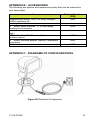
1
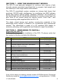
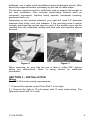
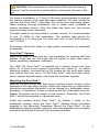
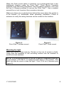
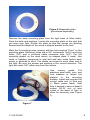
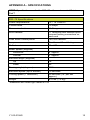
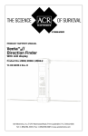
CAUTION: Before proceeding to install, test or use your new
ACR Electronics’ product, please read this Product Support Manual
in its entirety.
If you have questions regarding the contents of the manual, please
contact our Technical Service Department at ACR Electronics, Inc.,
Telephone +1 (954) 981- 3333 or email at
[email protected]. Please be ready to provide the
technician with the page number you wish to discuss. If you have a
question that is not covered in the manual, please visit our website
and access the Frequently Asked Questions (FAQs) section for
further information or call our Technical Service Department. The
website address is www.acrelectronics.com. If in the future you
lose this manual, you may access and print a replacement on the
ACR website.
Table of Contents
SECTION 1 - HOW THE SEARCHLIGHT WORKS _________________ 3
SECTION 2 - PREPARING TO INSTALL ________________________ 3
SECTION 3 - INSTALLATION ________________________________ 6
SECTION 4 - OPERATION _________________________________ 10
SECTION 5 - CARE AND MAINTENANCE _____________________ 10
APPENDIX A - SPECIFICATIONS ____________________________ 15
APPENDIX B - ACCESSORIES _______________________________ 16
APPENDIX C - DIAGRAMS OF CONFIGURATIONS _______________ 16
APPENDIX D - WARRANTY, USEFUL LIFE POLICY, NOTICES _______ 18
PLEASE READ ALL WARNINGS, CAUTIONS
AND NOTES CAREFULLY
Y1-03-0158G
2
SECTION 1 - HOW THE SEARCHLIGHT WORKS
The RCL-75 was specially designed for mariners who require a high
intensity remote controlled searchlight that is compact, light weight and
can stand up to the tough marine environment.
The RCL-75 searchlight system contains an intense light beam that
produces 180,000 peak candlepower by combining two 55W halogen
lamps with unique optical quality, parabolic reflectors. All functions of
the searchlight can be electrically operated by remote control from the
pilot area of the vessel using the remote control Point Pad™ and
interconnecting cable supplied with the RCL-75.
The sleek, robust design and modern construction materials of the
searchlight body makes it attractive for recreational and commercial
vessels. The searchlight is made of a UV resistant ASA plastic to
minimize yellowing, and is gasketed and finished to repel the weather.
SECTION 2 - PREPARING TO INSTALL
Unpacking the RCL-75
Before proceeding with the installation of the RCL-75, please verify that
the content of the box includes the following:
QTY
1
1
1
1
4
4
4
4
1
2
1
1
1
1
1
1
1
ITEM
Light assembly
Deck mount
17’ wire harness
Remote control Point Pad™ and extra
cover for flush mounting
S/S Allen bolts
S/S nuts
S/S flat washers
S/S lock washers
Special L wrench (Allen wrench and
Phillips head screwdriver)
U clamps for remote control Point Pad™
flush mount
Mounting gasket
Surface mount gasket
Flush mount gasket
Product Support Manual
Light base mount template*
Remote control panel template (flush)*
Remote control panel template (surface)*
ACR PART NUMBER
A3-06-2177
A1-18-1724
9426
9428
A1-05-0734-1
A1-05-0736
A1-05-0741
A1-05-0737
T1-04-0047
A1-17-1366
A1-25-0132
A1-25-0135-1
A1-25-0135-2
Y1-03-0158
Y1-03-0158-1
Y1-03-0158-1
Y1-03-0158-1
*Templates are on a separate sheet in this box.
If any of the above is missing, please contact ACR Electronics Technical
Service by email at service@acrelectronics,com or by phone at +1 (954)
Y1-03-0158G
3
981-3333. Please be ready to provide the serial number of your unit and
location of purchase.
Figure 1
Y1-03-0158G
4
Tools and fasteners needed for installation
The following tools and marine-grade fasteners are needed for
installation but are not included in the light kit.
4 each, 1/4” dia. bolts
4 each, Lock nuts
OR 4 each, 1/4” dia.
Lag screws
4 each,Washers
1 each, 1/4" Drill bit for bolt
holes
OR 1 each, 17/64" Drill
bit for lag screws
1 each, 15/16" Drill bit for cable clearance
1 each, 13/64" Drill bit for remote switch mounting bolts
1 each, Tube of silicone or bedding compound to close hole around
cable
OPTION: 1-inch mounting riser shapeable for irregular surfaces (P/N
9427, see Figure 6).
WARNING: Be careful when using electrical power tools around
water. Follow manufacturer’s instructions. Electric shock could occur.
Location Selection
Care and consideration should be given to the selection of a mounting
location for the RCL-75 and the Point Pad™ (remote control panel).
Location helps assure maximum performance of the light.
Typical mounting locations include bow pulpit, fore deck, and cabin
hardtop (see Figures 2 and 3).
CAUTION: Do not mount the searchlight upside down.
The mounting surface should be flat and parallel to the water’s surface.
Keep in mind that the further the light is from the pulpit, the greater the
chance that light will reflect off the boat and into the operator’s vision.
Before installing the light or remote control switch, find a suitable path
for the wires to run. There are two sets of wires: (a) a 17-foot (5.18
meter) wiring harness, which will connect the light and the remote Point
Pad™, and (b) power leads which will connect the light to a power
source. A path will be needed for both. Wire should be kept from contact
with sharp edges, and tight radii. If wire needs to pass through a
Y1-03-0158G
5
bulkhead, use a cable outlet (available at marine hardware stores). Wire
should be supported where necessary by the use of cable straps.
The location selected must be sufficiently rigid to support the weight of
the total installation. Also consider surrounding hazards such as
equipment movement, hatches being opened, accidental covering,
personnel traffic, etc.
Depending on the location selected, your light will need 1/4” diameter
stainless steel bolts, nuts, and washers. If the mounting area is robust
enough, pan-head lag screws may be used. If the surface area can be
reached from the underside, bolting with lock nuts and washers should
be used.
Figure 2
Figure 3
When mounting, be sure that the unit is able to rotate 360° without
hitting any obstructions. Refer to wiring section for additional
information.
SECTION 3 - INSTALLATION
Wiring
The RCL-75 has two wiring requirements:
1.) Connect the remote control Point Pad™ to the light
2.) Connect the light to 12-volt power with 15 amp rated wiring. The
light works best with 13.5 volts.
Y1-03-0158G
6
CAUTION: The connectors on each side of the wire harness are
different. Test fit connector to switch before running the harness to the
light.
For ease of installation, a 17-foot (5.18 meter) wiring harness to connect
the remote control to the light has been supplied. The wire should be
run from the Point Pad™ to the light. Do not run wire near sharp edges.
When passing through bulkheads, use a cable outlet (available at
marine hardware stores). After the cable has been run, the remote
control is ready to be connected.
The light needs to be connected to a power source. It is recommended
to use 14 AWG for this installation. The positive lead should be
connected to a 15 amp fuse. For wire runs over 16 feet (4.88 meters),
use 12 AWG.
Precautions should be taken to make power connections as watertight
as possible.
Point Pad™ Options
Make sure area is clean and dry. Use templates for marking drill hole
pattern. Verify that the drill holes will not impact or harm other items
(wires, plumbing, hardware, bulkhead).
The URP-102 Point Pad™ is supplied as a surface mount unit (see
figure 4). A flush mount option is provided (see figure 5). To switch
mounting options, unscrew the six (6) screws on the unit’s back plate
and remove the front cover. Fit the Point Pad™ with the flush mount
cover, replace the back plate, and screw the unit back together.
Mounting the Point Pad™
Both the surface mount and flush mount options require access to the
backside of the mounting location. Make sure there are no obstructions
behind the area where the switch is to be located (e.g. bulkheads, wires,
plumbing, or hardware). Check in advance that the coax cable from the
Master Controller can be routed to this location. Generally, the Point
Pad™ should be mounted in a protected area.
Install the surface mount Point Pad™ by drilling 3 holes in the
dashboard location using the Point Pad™ Surface Mount Template
supplied in the Mounting Templates. Mount the Point Pad™ to the
dashboard using the gasket, washers, and nuts supplied. Use a sealant
around the bolt holes to protect from moisture intrusion.
Y1-03-0158G
7
When the flush mount option is selected, cut a rectangular hole in the
dashboard location using the Point Pad™ Flush Mount Template
supplied in the Mounting Templates. Use the gasket, washers, nuts, and
the two U-Clamps provided to secure the Point Pad™. Use a sealant
around the cut out to protect from moisture intrusion.
Make sure there are no obstructions behind the area where the switch is
to be located. (i.e. bulkheads, wires, plumbing, hardware.) Check in
advance to verify the wiring harness can be routed to this location.
Figure 4Point Pad™ surface mount
Figure 5Point Pad™ flush mount
Mounting the Light
Make sure area is clean and dry. Decide on the use of screws or bolts.
Verify that the backside of the mounting surface can be reached to
install nuts and washers.
NOTE: If the mounting surface is not flat, a special, shapeable plate can
be purchased, (P/N 9427), to adapt the light base to the surface. This
plate can also be used to raise the light 1 inch (2.54 cm) if desired (see
Figure 6).
Y1-03-0158G
8
Figure 6-Shapeable plate
(purchased separately)
Remove the deck mounting plate from the light base (4 Allen bolts).
Save the bolts and washers. Locate the mounting plate on the spot that
you want your light. Rotate the plate so that the arrows are pointing
forward and the length of the arrow is aligned parallel to the keel.
Mark the 4 mounting holes, starting with the hole marked “Front” on the
mounting plate. Mounting holes are in 90° increments. Drill 4 mounting
holes (1/4") and a centered cable clearance hole (3/4"). Put the
mounting gasket on the deck mount (or shaped plate, if used). Use
caulk or bedding compound to seal bolt and wire holes before deck
mount is attached to deck. The plates are keyed to each other and to
the light: Be sure the arrows are pointing in the correct direction. The
light will rotate 180° either way from the arrows.
Use
marine
grade
316
stainless steel bolts, nuts, and
lock washers to fasten the
plate(s) to the mounting
surface. Install and connect the
control cable and (+) Red and
(-) Black power leads. Seal
hole if desired. Leave at least 8
inches (20.32 cm) of wire
coiled in the base of light to
allow for servicing (see Figure
7).
Figure 7
Y1-03-0158G
9
Seat the light assembly on the deck mount. Make sure the key is mated
and the gasket edge is not pinched. Reinstall the four (4 ) stainless steel
Allen bolts with the flat washer next to the plastic and the lock washer
under the bolt head. (Allen wrench for these bolts is furnished). Tighten
securely.
SECTION 4 - OPERATION
The remote control Point Pad™ is simple to operate. A red LED lights to
indicate that power is available. A green LED lights when the RCL-75 is
in use.
The ON/OFF button turns both dual beams ON and OFF together. The
control disk is pushed down in the direction you want to aim the light.
Elevation and rotation can be operated at the same time, with the light in
the ON or OFF mode.
SECTION 5 - CARE AND MAINTENANCE
General maintenance
The RCL-75 is relatively maintenance free. Clean the exterior of the light
with a mild detergent and water if desired. Rotate the light left, then right
and up then down periodically to keep motors and turning surfaces
clean and operational.
WARNING: DO NOT rotate the light manually. This will strip the
gear rack.
Bulb replacement
The bulbs are rated at over 200 hours of operation. If they should need
replacement, they can be ordered through an ACR dealer or ACR
Electronics. The part number is P/N 9403. ACR recommends that you
replace both bulbs at the same time.
CAUTION: Failure to follow replacement instructions carefully can
result in damage to bulb and/or light. All part sales are final.
NOTE: One bulb will continue to run if the other one burns out. The
100,000 cd intensity from one bulb will be sufficient to get back to shore.
CAUTION: ACR recommends that an experienced marine
mechanic replace bulbs according to these directions, or that the unit be
sent for evaluation and service.
To replace a bulb:
1)
Do not remove the front bezel to replace bulbs. Before replacing
bulb, move lens via remote control to the farthest down position.
Y1-03-0158G
10
Remove the light from its mounting location. Lamps should be
changed in an environment that includes good lighting and protection
from the weather, i.e., in a suitable work place.
2)
Remove top cover (4 top screws at sides of front, and 4 counter
sunk Phillips screws attaching top cover to lower case). Use L wrench
furnished with light (see Figure 8).
3)
Carefully remove top cover by lifting straight up (see Figure 9).
Figure 8
Figure 9
4) Observe shape and position of the bulb wire loop (see Figure 10).
5) Disconnect bulb wires from terminal block and with small wire snips,
remove the cable ties from bulb wires (see Figure 11).
Figure 10
Y1-03-0158G
Figure 11
11
6)
At the point where the grey bulb wire passes through the
partition wall, remove the sealant with a razor, screwdriver or snips.
Beneath the sealant is a wire sleeve. Hold this sleeve with needle
nose pliers and push through the partition wall (see Figure 12).
7)
Gently remove the entire reflector assembly from the body (see
Figure 13).
Figure 12
Figure 13
8)
Place the reflector assembly face down.
9)
Remove rubber sleeve (see Figure 14).
10) Squeeze the 2 wire ends of the G-clip together to release the
insert pin from the reflector and remove the clip (see Figure 15).
11)
Pull bulb out and discard.
Figure 14
Y1-03-0158G
Figure 15
12
12) Install new bulb, aligning the larger hole toward the back of the
tube with the G-clip hole. Do not touch bulb with bare hands (see
Figure 16).
13) Re-install G-clip.
14) Install the rubber sleeve over the base of the reflector, flush to
the G-clip.
15) Hold the reflector assembly in one hand and feed the bulb wires
through the partition (see Figure 17).
Figure 16
Figure 17
16) Seal metal sleeves on the bulb wires half way through the
partition wall (see Figure 18).
17) Set reflector housing into the swivel sockets with the light
pointed down and carefully engage the gear rack. Make sure the drain
hole and serial number is facing down.
18) Form the loops in the bulb wires in the same shape as the ones
removed. Looking into the back, the gear-toothed rack is on the right
and the smooth arch is on the left. The wires on the left are formed
sharply down and back of the bulb assembly, then a 1 inch (2.54cm)
diameter loop is formed back up and toward the smooth arch,
continuing around to pass through the partition below the lever switch.
The bulb wires on the right side are formed sharply up and back at the
back of the bulb assembly, then a 1 inch (2.54cm) diameter loop is
formed on the gear side and continued to pass through the partition
wall above the lever switch. These loops allow the elevation
movements and must not interfere with the lever switches or touch the
reflector.
19) When the bulbs are properly installed to this point, you will have
one long wire and one short wire for each bulb.
20) The short wire of the left bulb and the long wire of the right bulb
are joined together and inserted into the lower left hole of the terminal
Y1-03-0158G
13
block and screw tightened securely. Gather wires together and install
new cable ties (see Figure 19).
21) Replace the top cover carefully, making sure the partition is
seated in its proper groove and the screw holes at the front match the
metal braces.
22)
Reinstall the four (4) long cover screws starting from the
back and work forward, then install the two (2) top screws at each side
(total of 4). Tighten all screws securely, taking care not to over-tighten.
23)
The light assembly is ready to be reinstalled on mount.
Reattach control cable and wire power leads. Precautions should be
taken to make power connections as water tight as possible.
Figure 18
Figure 19
Y1-03-0158G
14
APPENDIX A - SPECIFICATIONS
NOTE: Specifications are for the RCL-75 with remote control Point
Pad™
RCL-75 Specifications
Power requirements
12 – 14 Volts DC
Current draw
10 Amps
Power wire leads
14 Gauge
Wire harness
17’ minimum with Molex® quick
connect locking connectors on
each end
Peak beam candle power
180,000 candela*
Lamp
Dual beam 55 watt halogen
Reflector size
6” x 4.5”
Beam spread (degrees)
Horizontal
8° Approx.
Vertical
3° Approx.
Elevation angle (degrees)
Up
18°
Down
45°
Turning angle (degrees)
360°
Elevation speed (top to bottom)
10 seconds
Turning speed (1 revolution)
20 seconds (18° per sec
approx.)
Weight
4.2 Lbs. (1.9 kg)
*Measured with direct light meter at 100’
Y1-03-0158G
15
APPENDIX B - ACCESSORIES
The following are options and replacement parts that can be ordered for
your searchlight:
Item
Replacement bulbs: 55W/12V lamp, halogen,
200hr operating life
Base gasket
nd
2 station cable harness, 17' (5.2m) length,
water proof connector
Riser, 1 inch (2.54cm): Can be stacked to raise
light
nd
2 station Point Pad™ control, flush mount or
surface mount
nd
2 station harness adapter (splitter), waterproof
connector
17’ cable harness extension
Product Number
(P/N)
9403
9425
9426
9427
9428
9442
9469
APPENDIX C - DIAGRAMS OF CONFIGURATIONS
Figure 20-Standard Configuration
Y1-03-0158G
16
Figure 21-Installation with extension cable harness
Figure 22-Installation with second Point Pad™ station
Y1-03-0158G
17
APPENDIX D - WARRANTY, USEFUL LIFE POLICY,
NOTICES
Limited Warranty
This product is warranted against factory defects in material and workmanship
for a period of 1 (one) year* from date of purchase or receipt as a gift. During
the warranty period ACR Electronics, Inc. will repair or, at its option, replace the
unit at no cost to you for labor, materials and return transportation from ACR.
For further assistance, please contact our Technical Service Department at ACR
Electronics, Inc., 5757 Ravenswood Road, Fort Lauderdale, FL 33312-6645.
Email: [email protected], Fax: +1 (954) 983-5087, Telephone: +1
(954) 981-3333.
This warranty does not apply if the product has been damaged by accident or
misuse, or as a result of service or modification performed by an unauthorized
factory. Except as otherwise expressly stated in the previous paragraph, THE
COMPANY MAKES NO REPRESENTATION OR WARRANTY OF ANY KIND,
EXPRESS OR IMPLIED, AS TO MERCHANTABILITY, FITNESS FOR A
PARTICULAR PURPOSE, OR ANY OTHER MATTER WITH RESPECT TO
THIS PRODUCT. The Company shall not be liable for consequential or special
damages.To
place
the warranty
in
effect,
register
online
at
www.acrelectronics.com or return the attached card within 10 days.
*Five years for the following products: EPIRB, PLB, S-VDR, SSAS.
Useful Life Policy
The typical service life of a properly maintained Product is limited to 12 years
from date of manufacture. Products that are 12 years and 1 month or older from
date of manufacture will not be serviced by ACR or our Battery Replacement
Centers. A Product that is 12 or less years old from date of manufacture will be
serviced as long as the unit appears fit to be placed back into its final
operational cycle. Service includes the replacement of those items that must be
replaced at service intervals and the verification that the device appears to be in
good mechanical and electrical working condition by an ACR authorized service
technician.
Notices
ACR Electronics diligently works to provide a high quality Product Support
Manual, however, despite best efforts, information is subject to change without
notice, and omissions and inaccuracies are possible. ACR cannot accept liability
for manual contents. To ensure that you have the most recent version of the
Product
Support
Manual,
please
visit
the
ACR
website
at
www.acrelectronics.com.
©2009 by ACR Electronics, Inc., part of Cobham plc. All rights reserved.
Reproduction in whole or in part is permitted only with permission of ACR
Electronics, Inc. Ongoing product improvements may change product
specifications without notice.
Trademarks or registered trademarks are the property of their respective
owners.
Y1-03-0158G
18
EC DECLARATION OF CONFORMITY
ACR Electronics, Inc. hereby declares that the following product is in conformity with
Directive 2004/108/EC of the European Parliament and of the Council of 15
December 2004 on Electromagnetic Compatibility (EMC Directive). In accordance
with the Directive, the product will be marked with the CE conformity marking as
follows:
Product:
Searchlight
Model: RCL-75
Regulations and
Standards:
EN 60945: 2002: Emissions:
CISPR 16-1:1999 (Conducted Emissions)
CISPR 16-1:1999 (Radiated Emissions)
EN 60945: 2002: Immunity:
IEC 61000-4-2: 1995 (Electrostatic Discharge)
IEC 61000-4-3: 1995 (Radiated Immunity)
IEC 61000-4-6: 1996 (Conducted Immunity, Power
and I/O Leads)
IEC 61000-4-11: 1994 (Voltage Dips and Interrupts)
Manufacturer:
ACR Electronics Inc.
5757 Ravenswood Road
Fort Lauderdale, FL 33312
USA
European
ACR Electronics Inc.
Representative: (European Office)
1 Rose Cottages, Pitmore Lane,
Sway, Lymington, Hampshire
SO41 6BX UK
Signed on behalf of ACR Electronics Inc.
Signed: __________________________________________
Name:
Kerry Greer
Title:
Executive Director Research & Development
Document RCL-75-002
Date:
February 26, 2009
This Declaration complies with
ISO/IEC 17050-1:2004
ACR Electronics, Inc. is registered by UL to ISO 9001:2000
Y1-03-0158G
19