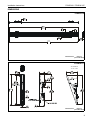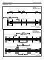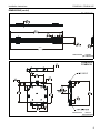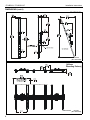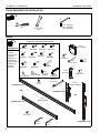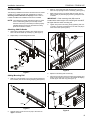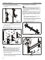
1
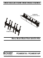
INSTALLATION INSTRUCTIONS
FCAB3X1U
(shown attached to LCM3X1U)
FCAB3X1UP
Menu Board Back Row Add-On Kits
Spanish Product Description
German Product Description
Portuguese Product Description
Italian Product Description
Dutch Product Description
French Product Description
FCAB3X1U / FCAB3X1UP
FCAB3X1U / FCAB3X1UP
Installation Instructions
DISCLAIMER
Milestone AV Technologies and its affiliated corporations and
subsidiaries (collectively "Milestone"), intend to make this
manual accurate and complete. However, Milestone makes no
claim that the information contained herein covers all details,
conditions or variations, nor does it provide for every possible
contingency in connection with the installation or use of this
product. The information contained in this document is subject
to change without notice or obligation of any kind. Milestone
makes no representation of warranty, expressed or implied,
regarding the information contained herein. Milestone assumes
no responsibility for accuracy, completeness or sufficiency of
the information contained in this document.
Chief® is a registered trademark of Milestone AV Technologies.
All rights reserved.
Table 1: Weight Capacity
MODEL
Max Weight
Allowed for EACH
Display
Total Max Weight
Capacity of
Mounting System
w/Accessory
FCAB3X1U
125 lbs
with LCM3X1U
(56.7 kg)
750 lbs (340.2 kg)
125 lbs
with LCM3X1UP
(56.7 kg)
750 lbs (340.2 kg)
FCAB3X1UP
WARNING: Never operate this mounting system if it is
damaged. Return the mounting system to a service center for
examination and repair.
IMPORTANT SAFETY INSTRUCTIONS
WARNING: Do not use this product outdoors.
WARNING: A WARNING alerts you to the possibility of
serious injury or death if you do not follow the instructions.
CAUTION: A CAUTION alerts you to the possibility of
damage or destruction of equipment if you do not follow the
corresponding instructions.
NOTE: The UL Listed FCAB add-on rows may be used with the
following UL Listed models: FCAB3X1U may be used
with LCM3X1U. FCAB3X1UP may be used with
LCM3X1UP.
--SAVE THESE INSTRUCTIONS-WARNING: Failure to read, thoroughly understand, and
follow all instructions can result in serious personal injury,
damage to equipment, or voiding of factory warranty! It is the
installer’s responsibility to make sure all components are
properly assembled and installed using the instructions
provided.
WARNING: Failure to provide adequate structural strength
for this component can result in serious personal injury or
damage to equipment! It is the installer’s responsibility to
make sure the structure to which this component is attached
can support five times the combined weight of all equipment.
Reinforce the structure as required before installing the
component.
WARNING: Exceeding the weight capacity can result in
serious personal injury or damage to equipment! It is the
installer’s responsibility to make sure the combined weight of
all components located within the mounting system of the
LCB2X1U/LCB2X1UP models does not exceed maximum
weights listed in Table 1.
2
Installation Instructions
FCAB3X1U / FCAB3X1UP
DIMENSIONS
FCAB3X1U
108.00
2743.2
DIMENSIONS:
INCHES
[MILLIMETERS]
FCAB3X1U
TILT RANGE
-5° TO +20°
16.75
425.5
DIMENSIONS:
INCHES
[MILLIMETERS]
3
FCAB3X1U / FCAB3X1UP
Installation Instructions
DIMENSIONS (cont’d)
FCAB3X1U
[400mm
Mounting Pattern]
15.75
400.0
DIMENSIONS:
INCHES
[MILLIMETERS]
FCAB3X1U
[600mm/800mm
Mounting Patterns]
23.62
600.0
DIMENSIONS:
4
INCHES
[MILLIMETERS]
Installation Instructions
FCAB3X1U / FCAB3X1UP
DIMENSIONS (cont’d)
FCAB3X1UP
68.00
1727.2
DIMENSIONS:
INCHES
[MILLIMETERS]
FCAB3X1UP
FCAB3X1U
7.02
178.3
DIMENSIONS:
INCHES
[MILLIMETERS]
LCB2X1UP
5
FCAB3X1U / FCAB3X1UP
Installation Instructions
DIMENSIONS (cont’d)
FCAB3X1UP
2.04
51.7
TILT RANGE
-5° TO +20°
DIMENSIONS:
INCHES
[MILLIMETERS]
FCAB3X1UP
[400mm
Mounting Pattern]
15.75
400.0
6
DIMENSIONS:
INCHES
[MILLIMETERS]
Installation Instructions
FCAB3X1U / FCAB3X1UP
LEGEND
Tighten Fastener
Pencil Mark
Apretar elemento de fijación
Marcar con lápiz
Befestigungsteil festziehen
Stiftmarkierung
Apertar fixador
Marcar com lápis
Serrare il fissaggio
Segno a matita
Bevestiging vastdraaien
Potloodmerkteken
Serrez les fixations
Marquage au crayon
Loosen Fastener
Drill Hole
Aflojar elemento de fijación
Perforar
Befestigungsteil lösen
Bohrloch
Desapertar fixador
Fazer furo
Allentare il fissaggio
Praticare un foro
Bevestiging losdraaien
Gat boren
Desserrez les fixations
Percez un trou
Phillips Screwdriver
Adjust
Destornillador Phillips
Ajustar
Kreuzschlitzschraubendreher
Einstellen
Chave de fendas Phillips
Ajustar
Cacciavite a stella
Regolare
Kruiskopschroevendraaier
Afstellen
Tournevis à pointe cruciforme
Ajuster
Open-Ended Wrench
Remove
Llave de boca
Quitar
Gabelschlüssel
Entfernen
Chave de bocas
Remover
Chiave a punte aperte
Rimuovere
Steeksleutel
Verwijderen
Clé à fourche
Retirez
By Hand
Optional
A mano
Opcional
Von Hand
Optional
Com a mão
Opcional
A mano
Opzionale
Met de hand
Optie
À la main
En option
Hex-Head Wrench
Security Wrench
Llave de cabeza hexagonal
Llave de seguridad
Sechskantschlüssel
Sicherheitsschlüssel
Chave de cabeça sextavada
Chave de segurança
Chiave esagonale
Chiave di sicurezza
Zeskantsleutel
Veiligheidssleutel
Clé à tête hexagonale
Clé de sécurité
7
FCAB3X1U / FCAB3X1UP
Installation Instructions
TOOLS REQUIRED FOR INSTALLATION
#2
1/8" (included)
3/16" (included)
M5 (included)
1/2" or 13mm
3/8"
PARTS
[Interface Bracket Hardware Kit]
(3 bags total - quantities listed per bag)
*PLEASE NOTE*
A (8)
M4x16mm
Several letters
have been
skipped in order
E (6)
to maintain
M5x20mm
consistency of
parts lettering
with parts listed in
LCM3X1U_UP
I (6)
installation
M8x20mm
instructions.
B (6)
M4x20mm
F (6)
M5x25mm
L (8)
.750x.323x.250
C (6)
M4x25mm
G (6)
M6x16mm
S (2)
[Add-on head]
D (6)
M5x16mm
H (6)
M6x25mm
T (6)
10-24 x 5/8"
V (6)
10-24
U (6)
10-24 x 2-1/4"
J (6)
M8x30mm
M (8)
.750x.344x.500
(FCAB3X1U only)
K (4)
M8x50mm
N (8)
[Universal
washer]
P (1)
M5
[In bag
labeled "N"]
W (2)
[End cap]
X (4)
1/4-20 x 1/2"
DD (4)
[T-slot nut]
AA (8)
5/16"
EE (6)
[Interface bracket]
OR
(FCAB3X1U only)
OR
(FCAB3X1UP only)
KK (1)
[Mounting Rail]
LL (8)
5/16" x 5/8"
SC (2)
3/16"
8
(FCAB3X1UP only)
SD (3)
1/8"
Installation Instructions
INSTALLATION
The following installation instructions assume that the UL Listed
LCM3X1U or LCM3X1UP has been assembled up until the
Attaching Interface Brackets to Displays section. Refer to
LCM3X1U/LCM3X1UP installation instructions for details.
NOTE: The following procedure assumes that two UL Listed
CPA or CMA ceiling plates (not included) and two
extension columns (not included) have been properly
installed following instructions provided with ceiling
plates and extension columns.
FCAB3X1U / FCAB3X1UP
3.
Slide top T-slot studs (DD) with attached lock nuts (AA)
down into top openings on add-on heads (S). (See Figure 3)
4.
Slide studs on lower T-slot studs (DD) into lower slots on
add-on heads (S) while bringing mounting rail against addon heads.
IMPORTANT ! : Both mounting rails (KK) must be
located at the same height. One mounting rail must NOT
be higher than the other mounting rail.
5.
Tighten array head to mounting rail by tightening lock nuts
on upper T-slot studs and adding two 5/16" lock nuts (AA) to
lower T-slot studs. (See Figure 3)
Attaching Add-On Heads
1.
Attach add-on head (S) to existing array head using four
5/16 x 5/8" button head cap screws (LL). (See Figure 1)
2.
Repeat Step 1 for remaining add-on head.
5
(S)
(AA) x 2
(S)
(KK)
1
(LL) x 4
Figure 3
Figure 1
Adding Mounting Rail
1.
6.
Repeat for remaining add-on head (S).
7.
Add one end cap (W) to each end of mounting rail (KK), and
fasten in place using two 1/4-20 x 1/2" Phillips self-tapping
screws (X) for each end cap. (See Figure 4)
Slide four T-slot studs (DD - two in top mounting rail slot and
two in bottom) into end of mounting rail (KK). (See Figure 2)
(DD) x 4
1
7
(X) x 2
(KK)
(W)
Figure 2
Figure 4
2.
Partially fasten one 5/16" lock nut (AA) to each stud on
upper T-slot studs.
9
FCAB3X1U / FCAB3X1UP
Installation Instructions
Attaching Displays to Ceiling Mount
Attaching Interface Brackets to Display
1.
Lower the latch mechanism on all interface brackets (EE).
(See Figure 5)
WARNING: IMPROPER INSTALLATION CAN LEAD TO
DISPLAY FALLING CAUSING SERIOUS PERSONAL
INJURY OR DAMAGE TO EQUIPMENT! The weight of the
displays must be evenly distributed as the displays are added
to the ceiling mount.
IMPORTANT ! : Install displays by placing the first display on
the mount, and then adding the second display on the other
side of the mount at the opposite end of the mount. Repeat for
remaining end displays, and add center displays last. (See
Figure 7)
(EE)
1
Latch
mechanism
1.
Ensure that the latch mechanisms on interface brackets
(DD) are already lowered. (See Figure 5)
2.
While supporting both sides of display, lower display onto
one side of ceiling mount, hooking top of interface brackets
onto rail of ceiling mount. (See Figure 8)
3.
Raise the latch mechanism on both interface brackets to
lock display in place. (See Figure 8)
Figure 5
2.
1
Align the center of the interface bracket (EE) with center of
display. (See Figure 6)
NOTE: The diamond-shape hole in the bracket corresponds to
4
5
the center of the mount.
(L or M)
6
3
2
Figure 7
(N)
2
Center of
bracket
(EE)
3
(A-K)
2
Figure 6
3
WARNING: IMPROPER INSTALLATION CAN LEAD TO
DISPLAY FALLING CAUSING SERIOUS PERSONAL
INJURY OR DAMAGE TO EQUIPMENT! Using screws of
improper size may damage your display. Properly sized
screws will easily and completely thread into display
mounting holes. If spacers are required, be sure to use longer
screws of the same diameter.
3.
10
Select correct screws, spacers (if necessary) and universal
washers from the hardware bag (A-N) and attach brackets
(EE) to back of displays. (See Figure 6)
3
Latch
mechanism
Figure 8
Installation Instructions
FCAB3X1U / FCAB3X1UP
4.
Fasten bracket against ceiling mount extrusion using one
10-24 x 5/8" button head cap screw (T). (See Figure 9)
5.
Repeat for other interface bracket.
5
4
Tilt
The interface brackets allow -5° to 20° tilt, and can be locked at
0°, 10° and 20° tilt.
3.
If necessary, loosen button head tilt friction bolt (located on
side of interface bracket). (See Figure 11)
4.
Adjust tilt as required. (See Figure 11)
5.
The tilt may be locked at 0°, 10° and 20° using one
10-24 x 2-1/4" Phillips head screw (U) and one 10-24 lock
nut (V) per interface bracket. (See Figure 11)
6.
Tighten button head tilt friction bolt as necessary. (See
Figure 11)
(T)
3
Figure 9
6.
5
Tilt
(U)
friction
bolt
Repeat Steps 1 through 5 for all remaining displays.
Adjustments
6
CAUTION: Watch for pinch points! Do not place fingers
between moveable parts.
Lock at
20° tilt
Height Adjust
(V)
The ceiling mounts allow up to 2 inches of height adjustment.
1.
Turn the height adjustment bolt(s) in the direction necessary
for the desired height. (See Figure 10)
Lock at
10° tilt
NOTE: Each height adjustment bolt controls the height on its
side of the mount.
IMPORTANT ! : Both mounting rails must be located at the
same height. One mounting rail must NOT be higher than the
other mounting rail.
2.
Lock at
0° tilt
Stop adjusting when the desired setting is reached.
4
(Displays not shown)
Figure 11
Security (OPTIONAL)
1.
Add padlock (not included) to each interface bracket to lock
display to ceiling mount. (See Figure 12)
Height
1 adjustment
bolts
1
Padlock
(Optional)
Figure 10
Figure 12
11
FCAB3X1U / FCAB3X1UP
Installation Instructions
USA/International
Europe
Chief Manufacturing, a products division
of Milestone AV Technologies
8800-002383 Rev00
2013 Milestone AV Technologies, a
Duchossois Group Company
www.chiefmfg.com
11/13
Asia Pacific
A
P
F
A
P
F
A
6436 City West Parkway, Eden Prairie, MN 55344
800.582.6480 / 952.225.6000
877.894.6918 / 952.894.6918
Franklinstraat 14, 6003 DK Weert, Netherlands
+31 (0) 495 580 852
+31 (0) 495 580 845
Office No. 1 on 12/F, Shatin Galleria
18-24 Shan Mei Street
Fotan, Shatin, Hong Kong
P 852 2145 4099
F 852 2145 4477