1
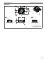
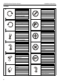
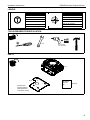
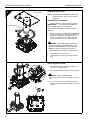
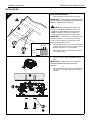
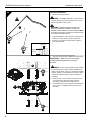
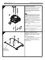
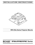
INSTALLATION INSTRUCTIONS
RSM Elite Series Projector Mounts
RPA Elite Series Projector Mount
RPA Elite Series Projector Mount
RPA Elite Series Projector Mount
RPA Elite Series Projector Mount
RPA Elite Series Projector Mount
RPA Elite Series Projector Mount
RSM A-D
RSM Elite Series Projector Mounts
Installation Instructions
DISCLAIMER
Milestone AV Technologies, and its affiliated corporations and
subsidiaries (collectively, "Milestone"), intend to make this
manual accurate and complete. However, Milestone makes no
claim that the information contained herein covers all details,
conditions or variations, nor does it provide for every possible
contingency in connection with the installation or use of this
product. The information contained in this document is subject
to change without notice or obligation of any kind. Milestone
makes no representation of warranty, expressed or implied,
regarding the information contained herein. Milestone assumes
no responsibility for accuracy, completeness or sufficiency of
the information contained in this document.
damaged. Return the mounting system to a service center for
examination and repair.
WARNING: Do not use this product outdoors.
IMPORTANT ! : The RSM mounts are designed to be:
WARNING: A WARNING alerts you to the possibility of
mounted to a 1-1/2" NPT or NPSM following ANSI/
ASME B1.20.1 (Schedule 40, 0.154" minimum
thickness aluminum- ASTM B221) threaded extension
column.
mounted to double 2" x 4" wood stud cross bracing
(1-1/2" on center) between two 2" x 4" ceiling joists;
with a maximum drywall covering of 5/8".
mounted to a concrete ceiling with a minimum
thickness of 8" and a maximum drywall covering of
5/8"; or
suspended from four 1/4" diameter (minimum) Grade 2
or better threaded rods (not included) which are
secured to unistrut, angle or channel assembly
overhead structural members (trusses or I-beams) by
Grade 2 or better 1/4" channel nuts (not included).
serious injury or death if you do not follow the instructions.
--SAVE THESE INSTRUCTIONS--
Chief® is a registered trademark of Milestone AV Technologies.
All rights reserved.
IMPORTANT SAFETY INSTRUCTIONS
CAUTION: A CAUTION alerts you to the possibility of
damage or destruction of equipment if you do not follow the
corresponding instructions.
WARNING: Failure to read, thoroughly understand, and
follow all instructions can result in serious personal injury,
damage to equipment, or voiding of factory warranty! It is the
installer’s responsibility to make sure all components are
properly assembled and installed using the instructions
provided.
WARNING: Failure to provide adequate structural strength
for this component can result in serious personal injury or
damage to equipment! It is the installer’s responsibility to
make sure the structure to which this component is attached
can support five times the combined weight of all equipment.
Reinforce the structure as required before installing the
component.
WARNING: Exceeding the weight capacity can result in
serious personal injury or damage to equipment! It is the
installer’s responsibility to make sure the combined weight of
all components attached to the RSM does not exceed 25 lbs
(11.34 kg).
•
The weight capacity of the RSM may be LIMITED to the
lowest weight capacity of any other components
located between the RSM and the supporting structure!
WARNING: Use this mounting system only for its intended
use as described in these instructions. Do not use
attachments not recommended by the manufacturer.
2
WARNING: Never operate this mounting system if it is
•
•
•
•
Installation Instructions
RSM Elite Series Projector Mounts
DIMENSIONS
57.8
2.28
BOLT CIRCLE
40.9
1.61
55.4
2.18
40.9
1.61
110.9
4.37
INTERFACE LOCKING SWITCH
5.6
.22
YAW ADJUSTMENT POINT
10
THREADS ONTO 1-1/2' NPT
PITCH ADJUSTMENT POINT
15
128.7
5.07
46.4
1.83
ROLL ADJUSTMENT POINT
4
NOTE: CUSTOM INTERAFCE BRACKET
NOT SHOWN. THE CUSTOM INTERFACE
BRACKET NEEDED FOR YOUR PROJECTOR
WILL ADD DEPTH TO INSTALLATION AND
THE MOUNT.
SEE SSM-XXX DRAWING ALSO.
3
RSM Elite Series Projector Mounts
Installation Instructions
LEGEND
4
Tighten Fastener
Pencil Mark
Serrez les fixations
Marquage au crayon
Serrare il fissaggio
Segno a matita
Befestigungsteil festziehen
Stiftmarkierung
Apretar elemento de fijación
Marcar con lápiz
Bevestiging vastdraaien
Potloodmerkteken
Apertar fixador
Marcar com lápis
Loosen Fastener
Drill Hole
Desserrez les fixations
Percez un trou
Allentare il fissaggio
Praticare un foro
Befestigungsteil lösen
Bohrloch
Aflojar elemento de fijación
Perforar
Bevestiging losdraaien
Gat boren
Desapertar fixador
Fazer furo
Phillips Screwdriver
Adjust
Tournevis à pointe cruciforme
Ajuster
Cacciavite a stella
Regolare
Kreuzschlitzschraubendreher
Einstellen
Destornillador Phillips
Ajustar
Kruiskopschroevendraaier
Afstellen
Chave de fendas Phillips
Ajustar
Hex-Head Wrench
Remove
Clé à tête hexagonale
Retirez
Chiave esagonale
Rimuovere
Sechskantschlüssel
Entfernen
Llave de cabeza hexagonal
Quitar
Zeskantsleutel
Verwijderen
Chave de cabeça sextavada
Remover
Open-Ended Wrench
Optional
Clé à fourche
En option
Chiave a punte aperte
Opzionale
Gabelschlüssel
Optional
Llave de boca
Opcional
Steeksleutel
Optie
Chave de bocas
Opcional
By Hand
Security Wrench
À la main
Clé de sécurité
A mano
Chiave di sicurezza
Von Hand
Sicherheitsschlüssel
A mano
Llave de seguridad
Met de hand
Veiligheidssleutel
Com a mão
Chave de segurança
Installation Instructions
RSM Elite Series Projector Mounts
LEGEND
Hammer
Target of Projector
Martillo
Punto de enfoque del proyector
Hammer
Ziel des Projektors
Martelo
Mira do projector
Martello
Punto di proiezione
Hamer
Doel van de projector
Marteau
Cible du projecteur
TOOLS REQUIRED FOR INSTALLATION
7/16"
3/32" (wood)
1/4" (concrete)
PARTS
A (1)
B (1)
All-Points
Security
Kit
(Optional)
Example Only
(Interface bracket
varies dependent
on projector model)
5
RSM Elite Series Projector Mounts
1
Installation Instructions
RSM INSTALLATION
(not included)
NOTE: Models RSM-A/RSM-B/RSM-C/RSM-D are
identical EXCEPT each provides a different
keyed lock.
Threaded Pipe Installation
1.
(not included)
Carefully determine required mounting location.
IMPORTANT ! : This will require knowing the
lens to screen distance. See projector
specifications for details on determining this
distance.
2
4
2.
3
Install 1-1/2" NPT or NPSM following ANSI/ASME
B1.20.1 (Schedule 40, 0.154" minimum thickness
aluminum - ASTM B221) threaded extension
column (not included) into threaded collar until
tight, with a minimum of four threads engaged.
WARNING: IMPROPER INSTALLATION CAN
RESULT IN SERIOUS PERSONAL INJURY OR
DAMAGE TO EQUIPMENT! Structural members
MUST be capable of supporting five times the
combined weight of all equipment being mounted.
(A)
3.
Align RSM with end of NPT pipe.
4.
Thread RSM up onto pipe by turning until hand
tight.
Rough Alignment of RSM
2
1
1.
Turn RSM clockwise or counter-clockwise until
front of mount is facing target.
2.
Secure RSM to pipe by turning set screw until tight.
CAUTION: DO NOT OVERTIGHTEN!
(A)
Overtightening of setscrew can damage threads on
pipe.
3.
3
1
(bottom view)
6
Turn security screw using a Phillips screwdriver
until set screw cannot be seen through access hole
in RSM.
Installation Instructions
RSM Elite Series Projector Mounts
INSTALLATION
Wood Stud Installation
1a
1.
Carefully determine required mounting location.
IMPORTANT ! : This will require knowing the lens
to screen distance. See projector specifications for
details on determining this distance.
WARNING: IMPROPER INSTALLATION CAN
1
RESULT IN SERIOUS PERSONAL INJURY OR
DAMAGE TO EQUIPMENT! Structural members
MUST be capable of supporting five times the
combined weight of all equipment being mounted.
IMPORTANT ! : The RSM mounts are designed to be
mounted to double 2" x 4" wood stud cross bracing
(1-1/2" on center) between two ceiling joists; with a
maximum drywall covering of 5/8".
x4
Ø 2.5mm
(Ø 3/32”)
2
2.
Using the RSM as a guide, mark four mounting hole
locations with a pencil or similar tool. Hole locations
must be centered on 2" x 4" cross braces.
3.
Drill four 3/32" (2.5mm) dia. pilot holes to a depth of
1-3/4" (45mm) deep.
4.
Align four mounting holes in RSM with four pilot
holes.
x4
45mm
(1-3/4”)
3
IMPORTANT ! : Make sure mount is properly
oriented towards target before securing to
structure.
5.
Secure RSM to structure using four #10 flat washers
and four #10 x 3" Phillips head wood screws (not
included).
4
(A)
x4
5
7
RSM Elite Series Projector Mounts
Installation Instructions
1b
Concrete Installation
1.
Determine mounting location.
WARNING: The RSM is designed to be mounted to a
concrete ceiling with a minimum thickness of 8" and a
maximum drywall covering of 5/8".
1
WARNING: IMPROPER INSTALLATION CAN
RESULT IN SERIOUS PERSONAL INJURY OR
DAMAGE TO EQUIPMENT! Structural members MUST
be capable of supporting five times the combined weight
of all equipment being mounted.
2.
Using the RSM as a guide, mark four mounting hole
locations on ceiling using a pencil or similar tool.
3.
Drill four 1/4" (6.3mm) dia. pilot holes to a depth of
2-1/2" (64mm) deep.
x4
2
Ø 6.3mm
(Ø 1/4”)
x4
3
64mm
(2-1/2”)
4.
Align four mounting holes in RSM with four pilot holes.
IMPORTANT ! : Make sure mount is properly
oriented towards target before securing to
structure.
4
WARNING: Anchors (not provided) must be installed
into structurally sound solid concrete. Installation into
hollow concrete block, mortar, or concrete that exhibits
cracking, spalling, or other defects may result in failure
of anchor and serious personal injury or damage to
equipment.
x4
5
5.
Install four 3/8" x 2-1/4" Grade 2 concrete anchors
(not included) by inserting into pilot holes and
pounding in until flush with mounting surface.
6.
Secure RSM to structure using four #10 flat washers
and four #10 x 3" Phillips head wood screws (not
included).
(A)
x4
6
8
Installation Instructions
1c
RSM Elite Series Projector Mounts
1
Threaded Rod Installation
2
The RSM must be suspended from four 1/4" diameter
(minimum) Grade 2 or better threaded rods (not
included) which are secured to unistrut, angle or
channel assembly overhead structural members
(trusses or I-beams) by Grade 2 or better 1/4" channel
nuts (not included).
WARNING: IMPROPER INSTALLATION CAN
4
RESULT IN SERIOUS PERSONAL INJURY OR
DAMAGE TO EQUIPMENT! Structural members
MUST be capable of supporting five times the
combined weight of all equipment being mounted.
(A)
1.
Carefully determine required mount position.
IMPORTANT ! : This will require knowing the lens
to screen distance. See projector specifications
for determining this distance.
NOTE: Threaded rod and installation hardware not
included.
5
x4
2.
Secure one end of the threaded rod to the structural
member.
3.
Install four #10-24 jam nuts on each threaded rod.
4.
Install the RSM on the threaded rod.
NOTE: Hole in the RSM allows socket wrench access
without unit disassembly.
2
PROJECTOR INSTALLATION
IMPORTANT ! : Model RSM uses optional Chief
"SSM" Series interface brackets. (See Parts
drawing.)
Install Interface Bracket
1.
Partially thread thumb nuts onto Phillips screws until
screw end is visible in top of thumb screw.
IMPORTANT ! : DO NOT fully tighten thumb
screws at this time.
Example Only
(Interface bracket
varies dependent
on projector model)
9
RSM Elite Series Projector Mounts
Installation Instructions
Example Only
(Interface bracket
varies dependent
on projector model)
2a
WARNING: IMPROPER INSTALLATION CAN
LEAD TO PROJECTOR FALLING RESULTING IN
SERIOUS PERSONAL INJURY OR DAMAGE TO
EQUIPMENT. DO NOT substitute hardware. Use only
the hardware provided by the manufacturer.
1
1.
Secure interface bracket to mount using installation
instructions and hardware provided with interface
bracket.
NOTE: Interface brackets can be installed using the
optional All-Points Security Kit included with
the SSM mounting solutions.
2b
Install Projector With Interface Bracket
Example Only
(Interface bracket
varies dependent
on projector model)
Orient projector with interface bracket as shown in
figure 2b at left.
2.
Lift projector so that screws with thumb nuts are
aligned with mounting slots in mount base.
3.
Slide projector with mounting bracket onto mounting
slots in mount base until screws are seated against
the back of mounting slots. See figure 2b and 2c.
WARNING: IMPROPER INSTALLATION CAN
1
(A)
(B)
10
1.
LEAD TO PROJECTOR FALLING RESULTING IN
SERIOUS PERSONAL INJURY OR DAMAGE TO
EQUIPMENT. Make certain mounting slots in mount
base slide under thumb screws and that screws are
seated in the back of slots.
Installation Instructions
2c
RSM Elite Series Projector Mounts
Securing Projector with Interface Bracket
to Model RSM Mount
Example Only
(Interface bracket
varies dependent on
projector model)
WARNING: IMPROPER INSTALLATION CAN
LEAD TO PROJECTOR FALLING RESULTING IN
SERIOUS PERSONAL INJURY OR DAMAGE TO
EQUIPMENT. Make certain mounting slots in mount
base slide under thumb screws and that screws are
seated in the back of slots.
1.
Verify mounting screws are properly seated in
mounting slots in mount base.
2.
Move locking lever to "Locked" position as shown
in figure 2c at left.
3.
Insert key into lock and turn to secure projector to
mount.
2
11
Installation Instructions
RSM Elite Series Projector Mounts
Example Only
(Interface bracket
varies dependent
on projector model)
3
ADJUSTMENTS
YAW Adjustment
1.
Loosen YAW adjustment locking screw using a #2
Phillips screwdriver.
2.
Turn YAW micro-adjustment screw right or left using
a #2 Phillips screwdriver until image is properly
aligned on target.
3.
Tighten YAW adjustment locking screw using a #2
Phillips screwdriver.
3
1
2
3a
Pitch Adjustment
1
3
1.
Example Only
(Interface bracket
2.
varies dependent
on projector model)
Loosen PITCH adjustment locking screw using a #2
Phillips screwdriver.
3.
Tighten PITCH adjustment locking screw using a #2
Phillips screwdriver.
Turn PITCH micro-adjustment screw right or left
using a #2 Phillips screwdriver until image is
properly aligned on target.
2
12
RSM Elite Series Projector Mounts
Installation Instructions
3b
Roll Adjustment
1
3
Example Only
(Interface bracket
varies dependent
on projector model)
2
13
1.
Loosen ROLL adjustment locking screw using a
#2 Phillips screwdriver.
2.
Turn ROLL micro-adjustment screw right or left
using a #2 Phillips screwdriver until image is
properly aligned on target.
3.
Tighten ROLL adjustment locking screw using a
#2 Phillips screwdriver.
RSM Elite Series Projector Mounts
14
Installation Instructions
Installation Instructions
RSM Elite Series Projector Mounts
15
RSM Elite Series Projector Mounts
Installation Instructions
USA/International
Europe
Chief Manufacturing, a products division
of Milestone AV Technologies
8832-002002 Rev02
2013 Milestone AV Technologies, a
Duchossois Group Company
www.chiefmfg.com
01/13
Asia Pacific
A
P
F
A
P
F
A
6436 City West Parkway, Eden Prairie, MN 55344
800.582.6480 / 952.225.6000
877.894.6918 / 952.894.6918
Franklinstraat 14, 6003 DK Weert, Netherlands
+31 (0) 495 580 852
+31 (0) 495 580 845
Office No. 1 on 12/F, Shatin Galleria
18-24 Shan Mei Street
Fotan, Shatin, Hong Kong
P 852 2145 4099
F 852 2145 4477