1
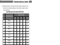
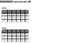
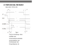
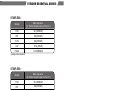
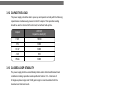
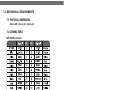
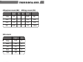
STRIDER ESSENTIAL SERIES
The essential gold standard
SST-ST70F-ESG
SST-ST60F-ESG
SST-ST50F-ESG
High efficiency with 80 PLUS Gold certification
24/7 continuous power output with 40℃ operating temperature
Class-leading single +12V rail
Strict ±3% voltage regulation and low ripple & noise
Multiple protection circuitry
PCI-E 8pin and PCI-E 6pin connectors support
Silent running 120mm fan with 18dBA minimum
Active PFC
SPECIFICATION
SilverStone Strider Essential
ST70F-ESG
ST60F-ESG
ST50F-ESG
ATX12V / EPS 12V Switching
Power Supply
With Active PFC
80Plus Gold
PS/2
1.0 GENERAL REQUIREMENTS
This specification describes a 700 / 600 / 500 watts power supply. With 5 output
remote ON/OFF control for ATX-12V system and a “Power factor correction
(active PFC)” circuit at 100V-240Vac.
01
STRIDER ESSENTIAL SERIES
2.0 INPUT REQUIREMENTS
The AC mains steady-state input voltage shall be 100 to 240 Vrms
The power supply shall operate from 90 to 264 Vrms.
The power supply shall operate from an AC mains frequency of 47-63Hz.
The AC mains steady-state RMS input current shall be:
SST-ST70F-ESG:
10Amp (maximum) at 100-127Vrms/60 Hz
5Amp (maximum) at 200-240Vrms/50 Hz.
SST-ST60F-ESG:
8Amp (maximum) at 100-127Vrms/60 Hz
4Amp (maximum) at 200-240Vrms/50 Hz.
SST-ST50F-ESG:
8Amp (maximum) at 100-127Vrms/60 Hz
4Amp (maximum) at 200-240Vrms/50 Hz.
3.0 OUTPUT REQUIREMENTS
3.1 OUTPUT VOLTAGE AND CURRENT
SST-ST70F-ESG:
MINIMUM NORMAL MAXIMUM LOAD
LINE
RIPPLE & NOISE
LOAD
LOAD
LOAD
REG
REG
+3.3V
0.2A
10A
25A
±5%
±1%
50mV P-P
+5V
1A
10A
25A
±5%
±1%
50mV P-P
+12V
1A
24A
56A
±5%
±1%
120mV P-P
-12V
0A
0.25A
0.3A
±10%
±2%
120mV P-P
+5Vsb
0A
1A
3A
±5%
±1%
50mV P-P
+5Vsb peak current is 4A(less then 0.5S)
(1) +3.3V & +5V total output not exceed 160W.
When +5V is load to 25A, the +3.3V maximum load is 10.6A.
When +3.3V is load to 25A, the +5V maximum load is 15.5A.
(2) All outputs shall be safety-isolated from the AC mains and share a common return.
This common return must be connected to supply chassis.
(3) Voltages and ripple are measured at the load side of mating connectors with a 0.1uF
monolithic ceramic capacitor paralleled by a 10uF electrolytic capacitor across the
measuring terminals.
02
LOAD REGULATION CHARACTERISTICS
OUTPUT LOAD
LOAD CONDITION
NO
+3.3V
+5V
+12V
-12V
+5Vsb
1
COND.1
X
X
X
X
3.5A
2
COND.2
X
X
X
X
3A
3
COND.3
1.5A
1A
1A
0A
0.1A
4
COND.4
25A
1A
8A
0A
0.1A
5
COND.5
1.5A
25A
8A
0A
0.1A
6
COND.6
1A
5A
56A
0A
0.1A
7
COND.7
3.6A
3.6A
2.6A
0.3A
3A
8
COND.8
10A
10A
24A
0.25A
1A
9
COND.9
15.86A
15.86A
46.09A
0.25A
2.47A
10
COND.10
14A
14A
52A
0.3A
3A
Cond. 10 only at 115Vac/60Hz and less then 1 S
Cond. 1 only at 115Vac/60Hz and less then 100 mS
SST-ST60F-ESG:
MINIMUM NORMAL MAXIMUM LOAD
LINE
RIPPLE & NOISE
LOAD
LOAD
LOAD
REG
REG
+3.3V
0.2A
10A
24A
±5%
±1%
50mV P-P
+5V
1A
10A
24A
±5%
±1%
50mV P-P
+12V
1A
22A
46A
±5%
±1%
120mV P-P
-12V
0A
0.25A
0.3A
±10%
±2%
120mV P-P
+5Vsb
0A
1A
3A
±5%
±1%
50mV P-P
+5Vsb peak current is 3.5A(less then 0.5S)
(1) +3.3V & +5V total output not exceed 130W.
When +5V is load to 24A, the +3.3V maximum load is 3A.
When +3.3V is load to 24A, the +5V maximum load is 10A.
(2) All outputs shall be safety-isolated from the AC mains and share a
common return. This common return must be connected to supply chassis.
03
STRIDER ESSENTIAL SERIES
(3) Voltages and ripple are measured at the load side of mating connectors with a 0.1uF
monolithic ceramic capacitor paralleled by a 10uF electrolytic capacitor across the
measuring terminals.
LOAD REGULATION CHARACTERISTICS
NO
OUTPUT LOAD
LOAD CONDITION
+3.3V
+5V
+12V
-12V
+5Vsb
1
COND.1
X
X
X
X
3.5A
2
COND.2
X
X
X
X
3A
3
COND.3
1.5A
1A
1A
0A
0.1A
4
COND.4
24A
1A
8A
0A
0.1A
5
COND.5
1.5A
24A
8A
0A
0.1A
6
COND.6
3A
6A
46A
0A
0.1A
7
COND.7
3.6A
3.6A
2.6A
0.3A
3A
8
COND.8
10A
10A
22A
0.25A
1A
9
COND.9
13.41A
13.41A
39.39A
0.26A
2.57A
10
COND.10
14A
14A
44A
0.3A
3A
Cond. 10 only at 115Vac/60Hz and less then 1 S
Cond. 1 only at 115Vac/60Hz and less then 100 mS
SST-ST50F-ESG:
MINIMUM NORMAL MAXIMUM LOAD
LINE
RIPPLE & NOISE
LOAD
LOAD
LOAD
REG
REG
+3.3V
0.2A
10A
24A
±5%
±1%
50mV P-P
+5V
1A
9A
20A
±5%
±1%
50mV P-P
+12V
1A
22A
39A
±5%
±1%
120mV P-P
-12V
0A
0.25A
0.3A
±10%
±2%
120mV P-P
+5Vsb
0A
1A
3A
±5%
±1%
50mV P-P
+5Vsb peak current is 3.5A(less then 0.5S)
04
(1) +3.3V & +5V total output not exceed 120W.
When +5V is load to 20A, the +3.3V maximum load is 7.5A.
When +3.3V is load to 24A, the +5V maximum load is 9A..
(2) All outputs shall be safety-isolated from the AC mains and share a common
return. This common return must be connected to supply chassis.
(3) Voltages and ripple are measured at the load side of mating connectors
with a 0.1uF monolithic ceramic capacitor paralleled by a 10uF electrolytic
capacitor across the measuring terminals.
LOAD REGULATION CHARACTERISTICS
NO
OUTPUT LOAD
LOAD CONDITION
+3.3V
+5V
+12V
-12V
+5Vsb
1
COND.1
X
X
X
X
3.5A
2
COND.2
X
X
X
X
3A
3
COND.3
1.5A
1A
1A
0A
0.1A
4
COND.4
24A
1A
7A
0A
0.1A
5
COND.5
1.5A
20A
7A
0A
0.1A
6
COND.6
3A
6A
39A
0A
0.1A
7
COND.7
3.6A
3.6A
2.6A
0.3A
3A
8
COND.8
10A
9A
20A
0.25A
1A
9
COND.9
13.25A
11.04A
32.15A
0.26A
2.47A
10
COND.10
12A
12A
36A
0.3A
3A
Cond. 10 only at 115Vac/60Hz and less then 1 S
Cond. 1 only at 115Vac/60Hz and less then 100 mS
3.2 REMOTE ON/OFF CONTROL
The power supply shall accept a logic open collector level which will disable/ enable all
the output voltage (exclude + 5V standby).
As logic level is low, outputs voltage were enabled.
As logic level is high, outputs voltage were disabled.
Note: 1. Logic high level: 2.0-5.25V while sourcing 0.2mA maximum.
2. Logic low level: 0-0.5V while sinking 1.6mA maximum.
3. Rise Time: 15ms maximum (10%-90%).
05
STRIDER ESSENTIAL SERIES
3.3 OUTPUT VOLTAGE HOLD-UP TIME
16.0 mS minimum : at 115V / 60 Hz. (80%LOAD)
3.4 OPERATION AT NO LOAD
The power supply shall be capable of being operated with no load on any or all outputs
without damage. For no load on +3.3V & +5V, the output shall not exceed +4.3V & +6.5Vdc
and the power supply may shutdown and require by remote-control or remove AC power restart.
3.5 PROTECTION
3.5.1 OVER-VOLTAGE PROTECTION
In the event of an over-voltage condition on +3.3 & +5Vdc &+12V the power supply shall
shutdown and require remote control or remove the AC mains input to reset the system.
+5V : 6.5V (maximum)
+3.3V : 4.3V (maximum)
+12V : 15.5V (maximum)
3.5.2 OVER- CURRENT PROTECTION
There shall be protection from an output over-current event. The PSU may shutdown
form such an event and require power-on restart. The overload currents should be
ramped at a minimum rate of 10 A/s starting from full load.
OVER-CURRENT TEST VALUES:
SST-ST70F-ESG:
Output Voltage
3.3V
5V
12V
Protecting trigger condition
< 60A
< 45A
< 62A
Output Voltage
3.3V
5V
12V
Protecting trigger condition
< 60A
< 45A
< 52A
Output Voltage
3.3V
5V
12V
Protecting trigger condition
< 60A
< 45A
< 46A
SST-ST60F-ESG:
SST-ST50F-ESG:
06
3.5.3 SHORT-CIRCUIT PROTECTION
An O/P short circuit is defined as any O/P impedance of less then 0.1 ohms. The power
supply shall shutdown and latch off for shorting +3.3V, +5V or +12V rail to return or any
other rail. and +5VSB shall not cause any damage to the power supply. The power supply
shall either shutdown and latch off or fold back for shorting negative rail. +5VSB must be
capable of being shorted indefinitely, but when the short is removed, the power supply
shall recover automatically or by cycling PS_ON#. The power supply shall be capable
withstanding a continuous short-circuit to the O/P without damage or overstress to the unit
(for example to components, PCB traces, connectors) under the I/P conditions specified.
3.6 OUTPUT RISETIME
The cold-start enable main output voltage rise-time of all outputs shall be measured with
maximum load on all outputs. (with COND.9)
Rise time: +3.3V
20mS (maximum)
(10-90%)
+5V
20mS (maximum)
+12 V
20mS (maximum)
-12 V
20mS (maximum)
The test condition: 115Vac/60Hz
3.7 OUTPUT OVERSHOOT/UNDERSHOOT
No output voltage shall overshoot / undershoot or generate spikes at turn-on or turn-off, during
momentary power loss, output short, or realistic input voltage or output load changes,
Overshoot/undershoot is defined as any output that exceeds the voltage tolerance plus or minus
an additional 5%. All outputs shall be measured with minimum load (COND.3)
Overshoot
Undershoot
+3.3V
3.63V
2.97V
+5V
5.5V
4.5V
+12V
13.2V
10.8V
-12V
-13.8V
-10.2V
+5Vsb
5.5V
4.5V
3.8 EFFICIENCY REQUIREMENT OF MAIN OUTPUT
The PSU should be at 87% efficiency with 100% of full load, at 90% efficiency with 50% of full
load and at 87% efficiency with 20% of full load in a “light” load or ideal condition. That should
be tested at nominal Input voltage is 115V/60Hz and load conditions defined in below Table.
07
STRIDER ESSENTIAL SERIES
ST70F-ESG:
loading
+12V
+5V
+3.3V
-12V
+5Vsb
100%
46.09A
15.86A
15.86A
0.25A
2.47A
50%
23.04A
7.93A
7.93A
0.12A
1.23A
20%
9.22A
3.17A
3.17A
0.05A
0.49A
loading
+12V
+5V
+3.3V
-12V
+5Vsb
100%
39.39A
13.41A
13.41A
0.26A
2.57A
50%
19.7A
6.71A
6.71A
0.13A
1.28A
20%
7.88A
2.68A
2.68A
0.05A
0.51A
loading
+12V
+5V
+3.3V
-12V
+5Vsb
100%
32.15A
11.04A
13.25A
0.25A
2.47A
50%
16.07A
5.52A
6.62A
0.12A
1.24A
20%
6.43A
2.21A
2.65A
0.05A
0.49A
ST60F-ESG:
ST50F-ESG:
3.9 EFFICIENCY REQUIREMENT OF STANDBY OUTPUT(230V/50Hz)
The +5Vsb supply efficiency should be greater then 50% with a minimun loading of 50mA and
input voltage is set up at 230Vac/50HZ when main O/P off ( PS_ON# high state).Meet Erp2013.
08
3.10 POWER GOOD SIGNAL TIME SEQUENCE
Measure condition :115V (FULL LOAD)
T1: PS_ON -- DC O/P within Spec.<500mS
T2: RISETIME < 20mS
T3: Power Good Delay Time 100mS-500mS
T4: Power Good Rise-time<10mS
T5: AC fail hold-up time>16mS
T6: Power Fail Delay Time>1mS
3.11 OUTPUT TRANSIENT RESPONSE
Expected output transient step sizes for each output. The transient load
slew rate is = 1.0 A/μs.
Table of DC Output Transient Step Sizes
ST70F-ESG:
Output
Max. step size
(% of rated output amps per Sec 3.1)
+12V
10A (10000uF)
+5V
8A (6000uF)
+3.3V
8A (6000uF)
-12V
0.1A (350uF)
+5Vsb
0.3A (6000uF)
(Adding external capactor)
09
STRIDER ESSENTIAL SERIES
ST60F-ESG:
Output
Max. step size
(% of rated output amps per Sec 3.1)
+12V
9A (10000uF)
+5V
8A (6000uF)
+3.3V
8A (6000uF)
-12V
0.1A (350uF)
+5Vsb
0.3A (6000uF)
(Adding external capactor)
ST50F-ESG:
Output
Max. step size
(% of rated output amps per Sec 3.1)
+12V
8A (10000uF)
+5V
8A (6000uF)
+3.3V
8A (6000uF)
-12V
0.1A (350uF)
+5Vsb
0.3A (6000uF)
(Adding external capactor)
Output voltages should remain within the regulation limits of Section 3.1, and
the power supply should be stable when subjected to load transients per above
table from any steady state load, including any or all of the following conditions:
• Load-changing repetition rate of 50 Hz to 10 kHz
•AC input range per Section 2.0
10
3.12 CAPACITIVE LOAD
The power supply should be able to power up and operate normally with the following
capacitances simultaneously present on the DC outputs. This capacitive loading
should be used to check all of function test, but without hold-up time.
Output
ATX12V
Capacitive load (uF)
+12V
10000
+5V
6000
+3.3V
6000
-12V
350
+5Vsb
6000
3.13 CLOSED-LOOP STABILITY
The power supply shall be unconditionally stable under all line/load/transient load
conditions including capacitive loads specified in Section 3.13. A minimum of
45 degrees phase margin and 10 dB gain margin is recommended at both the
maximum and minimum loads.
4.0 PHYSICAL ENVIRONMENT
4.1 TEMPERATURE
4.1.1 Operating Ambient: +0 to 40℃
4.1.2 Non-Operating Ambient(Storage): -40℃ to +70℃
4.2 HUMIDITY
4.2.1 Operating: To 85% relative humidity (non-condensing)
4.2.2 Non-Operating: To 95% relative humidity (non-condensing)
Note: 95%RH is achieved with a dry bulb temperature of 55℃ and
a wet bulb temperature of 54℃.
4.3 ALTITUDE
4.3.1 Operating: To 10,000ft
4.3.2 Non-Operating: To 50,000ft
11
STRIDER ESSENTIAL SERIES
5.0 REGULATORY COMPLIANCE
5.1 SAFETY REQUIREMENTS
-IEC 950
-TUV EN 60950
-NEMKO + CB REPOR
-CUL
5.2 DIELECTRIC STRENGTH
Primary to Frame Ground: 1800 Vac for 1 sec.
Primary to Secondary: 1800 Vac for 1 sec.
5.3 INSULATION RESISTANCE
Primary to Secondary: 20 Meg. ohms minimum.
Primary to FRAME GROUND: 20 Meg. ohms minimum.
5.4 GROUND LEAKAGE CURRENT
The power supply ground leakage current shall be less than 3.5mA.
5.5 EMISSION REQUIREMENTS
The power supply shall comply with CISPR 22, Class B, for both conducted
and radiated emissions with a 4dB margin..
6.0 OTHER REQUIREMENTS
6.1 INPUT CONNECTIONS
Refer to Mechanical Specifications for placement.The AC mains input are
through a three-circuit IEC type connector mounted on the rear of the
power supply chassis.
6.2 RELIABILITY
The power supply reliability, when calculated by “Bellcore” latest revision are
exceed 100,000 hours with all output at maximum load and an ambient
temperature of 25℃.
The special requirement is for cooling fan that MTTF be guarantee
over 20,000 hours at 40℃ ambient temperature.
12
7.0 MECHANICAL REQUIREMENTS
7.1 PHYSICAL DIMENSION
150 mm (W) × 86 mm (H) × 140mm (D)
7.2 CONNECTORS
M/B 24PIN connector
EPS 12V 8PIN connector
Yellow
Yellow
Signal
+12V
+12V
Pin
5
6
Pin
1
2
Signal
COM
COM
Black
Black
Yellow
Yellow
+12V
+12V
7
8
3
4
COM
COM
Black
Black
ATX 12V 4PIN (4+4PIN EPS 12V in split mode)
13
Black
Signal
GND
Pin
1
Pin
3
Signal
+12V
Yellow
Black
GND
2
4
+12V
Yellow
STRIDER ESSENTIAL SERIES
4PIN peripheral connector (HDD)
Yellow
Black
Black
Red
4PIN floppy connector (FDD)
Signal
Pin
Pin
Signal
+12V
COM
COM
+5VDC
1
2
3
4
1
2
3
4
+5VDC
COM
COM
+12V
Red
Black
Black
Yellow
SATA connector
Orange
Black
Red
Black
Yellow
Signal
Pin
+3.3V
COM
+5V
5
4
3
COM
+12V
2
1
8PIN PCI Express connector
Signal
Pin
Pin
Signal
+12V
+12V
1
2
5
6
COM
COM
Black
Black
+12V
COM
3
4
7
8
COM
COM
Black
Black
Signal
Pin
Pin
Signal
Yellow
+12V
1
4
COM
Black
Yellow
+12V
+12V
2
3
5
6
COM
COM
Black
Black
Yellow
Yellow
Yellow
Black sense1
6PIN PCI Express connector
Yellow
14
NO.G11220310