1
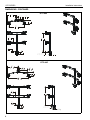
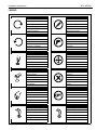
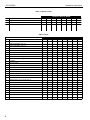
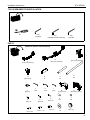
INSTALLATION INSTRUCTIONS
Instrucciones de instalación
Installationsanleitung
Instruções de Instalação
KTC-220
Istruzioni di installazione
Installatie-instructies
Instructions d´installation
KTC-225
KTC-320
KTC-230
KTC-325
KTC-330
KTC-440
KTC-445
Horizontal and Vertical Desk Clamp Stands
Spanish Product Description
German Product Description
Portuguese Product Description
Italian Product Description
Dutch Product Description
French Product Description
KTC SERIES
KTC SERIES
Installation Instructions
DISCLAIMER
Milestone AV Technologies and its affiliated corporations and
subsidiaries (collectively “Milestone”), intend to make this
manual accurate and complete. However, Milestone makes no
claim that the information contained herein covers all details,
conditions or variations, nor does it provide for every possible
contingency in connection with the installation or use of this
product. The information contained in this document is subject
to change without notice or obligation of any kind. Milestone
makes no representation of warranty, expressed or implied,
regarding the information contained herein. Milestone assumes
no responsibility for accuracy, completeness or sufficiency of
the information contained in this document.
Chief® and Centris™ are registered trademarks of Milestone
AV Technologies. All rights reserved.
IMPORTANT SAFETY INSTRUCTIONS!
WARNING: A WARNING alerts you to the possibility of
serious injury or death if you do not follow the instructions.
CAUTION: A CAUTION alerts you to the possibility of
damage or destruction of equipment if you do not follow the
corresponding instructions.
WARNING: Failure to read, thoroughly understand, and
follow all instructions can result in serious personal injury,
damage to equipment, or voiding of factory warranty! It is the
installer’s responsibility to make sure all components are
properly assembled and installed using the instructions
provided.
WARNING: Failure to provide adequate structural strength
for this component can result in serious personal injury or
damage to equipment! It is the installer’s responsibility to
make sure the structure to which this component is attached
can support five times the combined weight of all equipment.
Reinforce the structure as required before installing the
component.
WARNING: Failure to keep all mounted equipment directly
above the desk surface at all times can result in serious
personal injury or damage to equipment! All mounted
equipment must remain directly above the surface of the
desk in order to ensure and maintain a stable mount.
WARNING: Exceeding the weight capacity can result in
serious personal injury or damage to equipment! It is the
installer’s responsibility to make sure the weight of each
monitor attached does not exceed the weight limit for each
specific model. Refer to Table 1 for the weight limits for each
model.
2
WARNING: Use this mounting system only for its intended
use as described in these instructions. Do not use
attachments not recommended by the manufacturer.
WARNING: Never operate this mounting system if it is
damaged. Return the mounting system to a service center for
examination and repair.
WARNING: Do not use this product outdoors.
--SAVE THESE INSTRUCTIONS--
Installation Instructions
KTC SERIES
DIMENSIONS
13.68
347.4
KTC-220
2.25
57.2
3.63
92.1
5.88
149.2
23.83
605.4
1.96
49.8
1.90
48.3
13.25
336.6
.25
6.4
3.75
95.3
.50 [12.7] MIN
3.00 [76.2] MAX
2.75
69.9
17.24
437.8
3.63
92.1
2.25
57.2
KTC-225
6.87
174.6
30.51
774.8
1.96
49.8
1.90
48.3
13.25
336.6
.25
6.4
3.75
95.3
.50 [12.7] MIN
3.00 [76.2] MAX
2.75
69.9
3
KTC SERIES
Installation Instructions
DIMENSIONS - CONTINUED
3.63
92.1
3.26
82.7
KTC-230
2.25
57.2
5.50
139.6
1.90
29.75
755.6
.25
3.75
95.3
.50 [12.7] MIN
3.00 [76.2] MAX
2.75
69.9
KTC-320
3.63
92.1
20.80
528.3
2.25
57.2
8.13
206.5
37.14
943.3
1.96
49.8
1.90
48.3
13.25
336.6
.25
6.4
3.75
95.3
.50 [12.7] MIN
3.00 [76.2] MAX
2.75
69.9
4
Installation Instructions
KTC SERIES
DIMENSIONS - CONTINUED
KTC-325
3.63
92.1
26.90
683.4
2.25
57.2
10.51
[267.0]
47.70
[1211.6]
1.96
49.8
13.25
336.6
1.90
48.3
.25
6.4
3.75
95.3
.50 [12.7] MIN
3.00 [76.2] MAX
2.75
69.9
KTC-330
20.80
528.3
3.63
92.1
2.25
57.2
8.13
206.5
37.14
943.3
1.96
49.8
27.25
692.2
.25
6.4
1.90
48.3
3.75
95.3
.50 [12.7] MIN
3.00 [76.2] MAX
2.75
69.9
5
KTC SERIES
Installation Instructions
DIMENSIONS - CONTINUED
KTC-440
13.68
347.4
3.63
92.1
2.25
57.2
5.88
149.2
23.83
605.4
1.96
49.8
27.25
692.2
.25
6.4
3.75
95.3
.50 [12.7] MIN
3.00 [76.2] MAX
2.75
69.9
KTC-445
17.24
437.8
3.63
92.1
2.25
57.2
6.87
174.6
30.51
774.8
1.96
49.8
27.25
692.2
.25
6.4
3.75
95.3
6
.50 [12.7] MIN
3.00 [76.2] MAX
2.75
69.9
Installation Instructions
KTC SERIES
LEGEND
Tighten Fastener
Pencil Mark
Apretar elemento de fijación
Marcar con lápiz
Befestigungsteil festziehen
Stiftmarkierung
Apertar fixador
Marcar com lápis
Serrare il fissaggio
Segno a matita
Bevestiging vastdraaien
Potloodmerkteken
Serrez les fixations
Marquage au crayon
Loosen Fastener
Drill Hole
Aflojar elemento de fijación
Perforar
Befestigungsteil lösen
Bohrloch
Desapertar fixador
Fazer furo
Allentare il fissaggio
Praticare un foro
Bevestiging losdraaien
Gat boren
Desserrez les fixations
Percez un trou
Phillips Screwdriver
Adjust
Destornillador Phillips
Ajustar
Kreuzschlitzschraubendreher
Einstellen
Chave de fendas Phillips
Ajustar
Cacciavite a stella
Regolare
Kruiskopschroevendraaier
Afstellen
Tournevis à pointe cruciforme
Ajuster
Open-Ended Wrench
Remove
Llave de boca
Quitar
Gabelschlüssel
Entfernen
Chave de bocas
Remover
Chiave a punte aperte
Rimuovere
Steeksleutel
Verwijderen
Clé à fourche
Retirez
By Hand
Optional
A mano
Opcional
Von Hand
Optional
Com a mão
Opcional
A mano
Opzionale
Met de hand
Optie
À la main
En option
Hex-Head Wrench
Security Wrench
Llave de cabeza hexagonal
Llave de seguridad
Sechskantschlüssel
Sicherheitsschlüssel
Chave de cabeça sextavada
Chave de segurança
Chiave esagonale
Chiave di sicurezza
Zeskantsleutel
Veiligheidssleutel
Clé à tête hexagonale
Clé de sécurité
7
KTC SERIES
Installation Instructions
Table 1: Monitor Limits
MONITOR LIMITS By MODEL
DESCRIPTION
220
225
230
320
325
330
440
445
Weight
35 lbs
35 lbs
35 lbs
20 lbs
15 lbs.
15 lbs
20 lbs
15 lbs
Max Screen Width
22.7"
30"
N/A
18"
24.5"
18"
22.7"
30"
Max Screen Height
28"
28"
19.3"
28"
28"
18.5"
18.5"
18.5"
440
445
Table 2: Parts
QUANTITY By MODEL
ITEM DESCRIPTION
A
ARRAY ASSEMBLY, Dual, 27"
220
230
320
2
2
1
ARRAY ASSEMBLY, Triple, 54"
CENTRIS HEAD ASSEMBLY, Pole Mount
D
DESK CLAMP
330
1
ARRAY ASSEMBLY, Triple, 42"
C
325
1
ARRAY ASSEMBLY, Dual, 34"
B
225
2
1
2
1
1
1
2
E
SHEATH, Cable Management, 8"
1
1
F
POLE, Mount Freestanding, 14"
1
1
G
POLE, Mount Freestanding, 28"
H
BUMPER,
6
6
J
KEY, Hex, 5/32”
1
1
K
KEY, Hex, 3/16”
1
1
1
1
1
2
2
2
1
1
1
1
1
1
1
6
6
6
6
6
6
1
1
6
1
1
1
1
1
L
KEY, Hex, 7/32”
1
1
M
CLAMP, Pole 2" Pipe
1
1
N
CLAMP, Back Casting
P
SCREW, Phillips Pan Head, M4 x 12mm
8
8
1
1
1
1
1
1
1
1
2
2
2
12
12
24
16
16
2
8
Q
SCREW, Phillips Pan Head, M4 x 20mm
8
8
8
12
12
24
16
16
R
SCREW, Phillips Pan Head, M4 x 30mm
8
8
8
12
12
24
16
16
S
SPACER, Nylon, 3/8” (used with item Q)
8
8
8
12
12
24
16
16
T
SPACER, Nylon, 3/4” (used with item R)
8
8
8
12
12
24
16
16
U
SCREW, Button Head Cap, 1/4-20 x 3/4”
2
2
2
2
4
4
4
V
SCREW, Button Head Cap, 1/4-20 x 1 1/4”
6
W
SCREW, Flat Head Cap, 3/8-16 x 1"
1
1
X
WASHER, Flat, 1/4”
2
2
Y
PIPE CAP, 1.75 OD
1
1
8
1
1
1
1
1
1
1
2
2
4
4
4
1
1
1
1
1
Installation Instructions
KTC SERIES
TOOLS REQUIRED FOR INSTALLATION
5/32”
(included)
#2
3/16”
(included with 230 model only)
7/32”
(included)
PARTS
(REFER TO TABLE 2 FOR QUANTITIES)
C
B
[Triple array assembly]
A
[Pole mount assembly]
[Dual array assembly]
E
8"
D
[Desk clamp]
K
3/16”
J
7/32”
H
L
5/32”
[Bumper]
Q
P
M4 X 12
U
1/4-20 x 3/4”
G
28"
F
14"
R
M4 X 30
M
[2" pipe clamp]
S
3/4”
N
[Back casting clamp]
T
3/8”
M4 X 20
V
1/4-20 x 1 1/4”
W
3/8-16 x 1"
X
1/4”
Y
[Pipe cap]
9
KTC SERIES
Installation Instructions
INSTALLATION
Desk Clamp Installation
NOTE: In order to reduce the chance of scratching to the
mounting surface, bumpers may be installed. However,
installation of bumpers is optional.
1.
Remove adhesive from underside of bumpers (H).
2.
Attach bumpers (H) to underside of desk clamp (D). (See
Figure 1)
6
7
(D)
2
5
(H) x 6
(behind desk)
3
(W) x 1
Figure 2
8.
Turn clamp screw until the clamp is secured to the desk as
tightly as possible. (See Figure 3)
(F or G)
(view from bottom)
Figure 1
3.
Use 7/32” hex key (J) to install 3/8-16 x 1" flat head cap
screw (W) through the opening on top of desk clamp (D) and
into bottom of mounting pole (F or G). (See Figure 1)
4.
Determine the location where desk clamp will be mounted.
WARNING: Failure to keep all mounted equipment directly
above the desk surface at all times can result in serious
personal injury or damage to equipment! All mounted
equipment must remain directly above the surface of the
desk in order to ensure and maintain a stable mount.
5.
Place desk clamp (D) over desired mounting location on
desk. (See Figure 2)
6.
If there is not enough clearance behind the desk for the
device to clear, remove the bottom portion of the desk
clamp by using 5/32” hex key (L) to remove 2 connecting
screws. (See Figure 2)
7.
Reinstall bottom portion of the desk clamp (if necessary) by
reinstalling 2 connecting screws underneath desk. (See
Figure 2)
10
8
Figure 3
Installation Instructions
KTC SERIES
Mount Assembly
KTC-220, 225, 320, 325, 330, 440 and 445 Assembly
KTC-230 Assembly
1.
Assemble pole clamp back (M) to pole mount front using
two washers (X) and two 1/4-20 x 3/4” button head cap
screws (U) using a 5/32” hex key (J). (See Figure 6)
1.
Place front pole clamp with Centris Head (C) against pole
(G) in approximate mounting location.
2.
2.
Place three 1/4-20 X 1 1/4” button head cap screws (V) into
rear pole clamp (N) and place against pole aligning with
front pole clamp on Centris Head (C). (See Figure 4)
Secure pole mount back (M) to pole mount front and pole by
tightening two button head cap screws (U) using a 5/32” hex
key (J).
3.
Repeat steps 1-2 for additional array mount on KTC-330,
440 and 445.
4.
Add pipe cap (Y) to top of pole (F or G).
(G) x 1
Pole Mount front
with Array
(C) x 1
(X) x 2
(N) x 1
2
(V) x 3
Figure 4
(M) x 1
3.
Equally tighten screws (V) against front pole mount and the
rear pole clamp (N). (See Figure 5)
1
(U) x 2
Figure 6
Display Installation
(V) x 3
Attach Centris Head to Flush Mount Display
(N)
CAUTION: If display uses a screw size other than those
included in the kit, DO NOT use the screws provided. Using
the wrong screws could result in damage to your monitor.
Keep equal
distance between
mount and
clamp when
tightening
1.
(C)
Figure 5
4.
Secure rear pole clamp (N) to Centris head’s front pole
mount (C) and pole (G) by tightening three button head cap
screws (V) using 5/32” hex key (J). (See Figure 4)
5.
Repeat steps 1-4 for additional Centris head.
6.
Add pipe cap (Y) to top of pole (F or G).
Install two M4 x 12mm Phillips pan head screws (P) into two
upper mounting holes in display back using #2 Phillips
screwdriver. (See Figure 7)
NOTE: DO NOT fully tighten at this time.
2.
Hang display on Centris head. (See Figure 8)
3.
Install bottom two M4 x 12mm Phillips pan head screws (P)
through Centris head mounting holes and into lower
mounting holes in display back.
4.
Tighten ALL four M4 x 12mm Phillips pan head screws (P).
(See Figure 9)
11
KTC SERIES
Installation Instructions
Attach Centris Head to Recessed Mount Display
1
NOTE: Refer to Table 1 to select the applicable screw and
(P) x 2
spacer combination.
1.
Uninstall end lock using the 5/32” hex key (J). (See Figure
10)
2.
Slide Centris head off array rail. (See Figure 11)
Centris Head
Square Nut
Display
1
Figure 7
Array Rail
End Lock
Figure 10
Display
2
Array Rail
2
Array Rail
Centris Head
Centris Head
Figure 8
Figure 11
Display
3.
Place display face down on a clean dry surface.
4.
Place four 3/8” or 3/4” nylon spacers (S or T) over four
mounting holes in display back (See Figure 12).
5.
Align Centris head mounting holes with four nylon spacers
(See Figure 12).
6.
Secure Centris head to display using four M4 x 20mm
Phillips pan head screws (Q), or four M4 x 30mm Phillips
pan head screws (R). (See Figure 12).
Centris Head
Array Rail
3
(P) x 2
Figure 9
12
Installation Instructions
KTC SERIES
Array Rail
6 (Q or R) x 4
End Lock
Centris Head
5
4 (S or T) x 4
End Lock Retaining Screw
Centris Head
Figure 14
Display
ADJUSTMENTS
Display Adjustment
Figure 12
7.
Slide display with Centris bracket onto array rail. (See
Figure 13)
NOTE: Repeat previous steps for each additional display.
8.
Reinstall end locks into mounting rail using the 5/32” hex
key (J) (See Figure 14).
The KTC Series mount allows horizontal, pitch, and rotational
adjustment of each display.
The KTC Series mount also allows a full 360 deg. of display
rotation with a maximum pitch range of 15° up and 15° down.
The 3/16” hex key included with the KTC-230 mount is to be
used to adjust the rotation on this model.
Display Horizontal Position Adjustment
Display with Centris Bracket
To adjust display horizontal position:
1.
Loosen Centris bracket rear adjustment knob (See Figure
15).
2.
Slide Centris bracket with display left or right until properly
positioned on array rail.
3.
Tighten Centris bracket rear adjustment knob.
7
Horizontal
Adjustment
Knob
Array Rail
Figure 13
Figure 15
13
KTC SERIES
Installation Instructions
Display Pitch and Roll Adjustment
To adjust display pitch or roll position:
1.
Loosen Centris bracket front adjustment knob. (See Figure
16)
2.
Tilt display up or down, or adjust display roll left or right until
properly positioned.
3.
Tighten Centris bracket front adjustment knob.
Pitch/Roll
Adjustment
Knob
Figure 16
CABLE MANAGEMENT
The KTC Series mount includes cable management features
used to properly route and secure display cables.
To use the cable management features:
1.
Connect cables to display.
2.
Route cables through cable clips on array rail. (See Figure
17)
3.
Route cables down pole and away from mount and secure
to pole using sheath (E). (See Figure 17)
Cable Clips
(E)
Figure 17
4.
14
Repeat steps 1-3 for additional array on KTC-330, 440 and
445.
Installation Instructions
KTC SERIES
15
KTC SERIES
Installation Instructions
USA/International
Europe
Chief Manufacturing, a products division
of Milestone AV Technologies
8800-002425Rev 00
2013 Milestone AV Technologies, a
Duchossois Group Company
www.chiefmfg.com
05/13
Asia Pacific
A
P
F
A
P
F
A
6436 City West Parkway, Eden Prairie, MN 55344
800.582.6480 / 952.225.6000
877.894.6918 / 952.894.6918
Franklinstraat 14, 6003 DK Weert, Netherlands
+31 (0) 495 580 852
+31 (0) 495 580 845
Office No. 1 on 12/F, Shatin Galleria
18-24 Shan Mei Street
Fotan, Shatin, Hong Kong
P 852 2145 4099
F 852 2145 4477