1
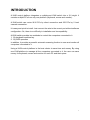
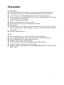
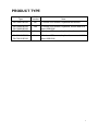
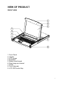
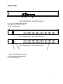
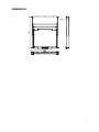
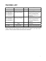
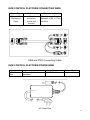
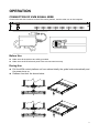
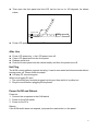
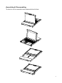
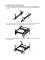
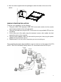
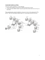
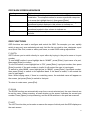
® DIGIUS TFT Console User Manual INTRODUCTION ........................................................................................................................... 3 FEATURES ................................................................................................................................... 4 PRODUCT TYPE .......................................................................................................................... 5 VIEW OF PRODUCT .................................................................................................................... 6 Front View .............................................................................................................................. 6 Dimension .............................................................................................................................. 8 KVM SWITCHES PACKING LIST ................................................................................................. 9 KVM Control Platform Connecting Wire ............................................................................... 10 KVM Control Platform Power Wire ....................................................................................... 10 OPERATION ................................................................................................................................ 11 CONNECTION OF KVM SIGNAL WIRE ............................................................................... 11 Before Use ............................................................................................................................ 11 During Use ............................................................................................................................ 11 After Use .............................................................................................................................. 12 Hot Plug ............................................................................................................................... 12 Power On/Off and Reboot .................................................................................................... 12 Assembling & Disassembling ............................................................................................... 13 Single Stage Installation ....................................................................................................... 15 Cascade Installation ............................................................................................................. 16 OSD OPERATION....................................................................................................................... 17 OSD Overview ..................................................................................................................... 17 OSD Navgation .................................................................................................................... 17 OSD Main Screen Headings ................................................................................................ 18 OSD Functions ..................................................................................................................... 18 SAFETY GUIDE .......................................................................................................................... 21 2 INTRODUCTION A KVM control platform integrates a multiple-port KVM switch into a 1U height. It controls multiple PCs from only one platform (keyboard, mouse and monitor). A KVM switch can control 8/16 PCs by direct connection and 256 PCs by 2 level cascade connection. It is easy and quick to install. Just connect the wire to the correct port without software configuration. So, there is no difficulty in installation and incompatibility. A KVM switch provides two methods to control the computers connected to it: 1. By keyboard combine key 2. By OSD operation In addition, it provides a powerful automatic scanning function to scan and monitor all computers connected to it. Using a KVM control platform is the best choice to save time and money. By using one KVM platform to manage all the computers connected to it, the user can save money for keyboard, mouse and monitor for each PC and their space. 3 FEATURES Control Platform Control platform with LCD, keyboard, mouse and multiple ports KVM switch 1U height, suitable for 19’’ standard cabinet installation and metal structure 17/19’’ LCD screen with high brightness, high clear and high resolution Control platform can be totally pulled out from the cabinet and the LCD screen can be turned on to 120 degrees Ultra thin keyboard with keypad Mouse touch board with two function button Front panel with lock to prevent damage by accident Built-in power Automatic power on/off. When pulling control platform out from cabinet, the power turns off automatically. When pushing it into the cabinet, the power turns on automatically An easy to use OSD menu Switch One control platform can control 8/16 PCs by direct connection One control platform can control 256 PCs by 2 level cascade connection Be compatible with PS/2, USB standard interface Supports VGA, SVGA, XGA video input Accord with DDC, DDC2, DDC2B standard and VESA standard Supports maximum resolution of 1920 x 1440p Support multiple operating systems: WIN95/98/98SE/ME/200/XP, WIN 7, WIN NT, UNIX, LINUX 4 PRODUCT TYPE Type DS-72001GE/US OSD Function No DS-72002GE/US DS-72003GE/US DS-72011GE/US Yes DS-72012GE/US DS-72013GE/US Yes No Note 17 inches LCD screen, keyboard and mouse 17 inches LCD screen, keyboard, mouse and 8/16 ports USB KVM 19 inches LCD screen, keyboard and mouse 19 inches LCD screen, keyboard, mouse and 8/16 ports USB KVM 5 VIEW OF PRODUCT FRONT VIEW 1 2 3 9 4 5 7 6 8 1. Front Panel 2. Handle 3. LCD screen 4. Keyboard 5. Mouse touch board 6. Rear hang ear channel 7. Guide 8. Front hang ear 9. LCD OSD control key 6 REAR VIEW 1 2 3 DS-72001GE/US – DS-72011GE/US (1) DC 12V 1000Ma power socket (2) USB keyboard & mouse port (3) PC connecting port DS-72002GE/US – DS-72012GE/US DS-72003GE/US – DS-72013GE/US 1 2 3 (1) DC 12V 1000Ma power socket (2) USB keyboard & mouse port (3) PC connecting port 7 DIMENSION 8 PACKING LIST Type Name Num/Uni t DS-72001GE/US DS-72002GE/US DS-72003GE/US KVM Control Platform 1 DS-72011GE/US DS-72012GE/US DS-72013GE/US KVM Control Platform 1 KVM Connecting Cable Power Cable User Manual 1/8/16 Cable AC Power User Manual 1 1 Note 17 inches LCD screen, keyboard and mouse control platform integrated KVM switch with multiple ports (8/16ports). 19 inches LCD screen, keyboard and mouse control platform integrated KVM switch with multiple ports (8/16ports). PS/2 Connecting and USB Connecting AC power connecting cable Manual Please check the lists carefully and contact with your dealer if you have some problems. Please read the manual carefully before installation. 9 KVM CONTROL PLATFORM CONNECTING WIRE Cable Type USB and PS/2 Connecting Cable KVM Port PC, or Server Port VGA port (Keyboard, mouse and monitor) VGA, Keyboard, Mouse (Standard USB & PS/2 Interface) USB and PS/2 Connecting Cable KVM CONTROL PLATFORM POWER WIRE Wire Type AC Power Wire Note 3 Plugs of National Standard Voltage Range 100~230V Machine Type All AC Power Wire 10 OPERATION CONNECTION OF KVM SIGNAL WIRE Connect the end with 8 sockets to the KVM control platform, and the other one to the computer. Before Use Make sure all the devices are safely grounded Make sure the KVM wire and power wire are connected correctly During Use Pull the KVM control platform out from cabinet totally, the guide locks automatically and the power turns on Release front lock. As shown below: 11 Then open the front panel and the LCD can be turn on to 120 degrees. As shown below: AUTO LOCK UNLOCK Press LCD power key (red), the LCD is on After Use Press LCD power key -> the LCD power turns off Close LCD panel and lock the front panel Release guide lock Push the control panel into the cabinet totally, and then the power turns off Hot Plug The KVM control platform supports hot plug. It can be connected and disconnected without turning power off. Please follow the steps: Hot plug PC connecting port: When hot plugging PC port: 1. The connecting wire must be plugged into the port from which it is pulled out 2. Plug the mouse before plugging the keyboard Power On/Off and Reboot Power on: 1. Connect the computers to the KVM switch 2. Power on the KVM switch 3. Power on the PCs Reboot: If the KVM switch does not respond, just press the reset button on the panel 12 Assembling & Disassembling The device can be assembled and disassembled as follows: 13 STANDARD RACK INSTALLATION 1. Screw the front flange to the rack first. Slide the bars with the rear flange towards the rack until the flanges gets contact with the rack, then screw the rear flanges to the rack. 2. Slide the switch onto the support flanges. Use the screws supplied with this package to loosely attach the front of the switch to the front of the rack. 3. Slide the rear attachment sliding brackets along the slide bars until they contact the rear of the switch. 14 4. Use the screws supplied with this package to attach the bars to the rear of the switch. SINGLE STAGE INSTALLATION To set up your installation, do the following: 1. Plug your USB / PS/2 keyboard, USB / PS/2 mouse and monitor into the console port section located on the unit’s rear panel 2. Using a KVM cable set, plug the DB 15 connector into any available CPU port on the switch 3. At the other end of the cable, plug the keyboard, mouse, video cables into their respective ports on the computer 4. Plug the power adapter cable into the switch’s power jack, then plug the power adapter into an AC power source 5. Repeat steps 2-4 for any other computers you are connecting up This completes the single stage installation, and you can turn on the power to the PCs. NOTE: The LCD KVM switch initially links to PC connected to the first CPU port. 15 CASCADE INSTALLATION To set up cascade installation, do the following: 1. Set up single installation as mentioned in SINGLE STAGE INSTALLATION. 2. Connect one end of HDB15 cable to IN port of upper KVM, and the other end to OUT port of lower KVM. This completes the cascade installation, and you can turn on the power to the PCs. NOTE: The LCD KVM switch initially links to PC connected to the first CPU port. 16 OSD OPERATION OSD OVERVIEW The On Screen Display (OSD) is used to handle all computer control and switching procedures. All procedures start from the OSD main menu. To pop up the main menu, tap the [Scroll Lock] twice. Note: You can optionally change the hotkey to the Ctrl key, in which case you would tap [ctrl] twice. If OSD menu is set as “console locked”, you must input password each time the main menu appears. If no password has been set, just press [Enter] to show main menu. OSD menu interface is shown as below: Note: OSD always starts in List View, with the highlight bar at the same position it was in the last time it was closed. OSD NAVIGATION To dismiss OSD, press [Esc]. To move up and down through the list one line at a time, use the Up and Down Arrow Keys. If there are more list entries than what can appear on the main screen, the screen will scroll. To activate a port, move the highlight bar to it then press [Enter]. After selecting a port, the OSD menu automatically disappear and a blue tip window appears to indicate the port currently selected. 17 OSD MAIN SCREEN HEADINGS Heading PN QV PC NAME Explanation This column lists the port numbers for all the CPU ports on the installation. The simplest method to access a particular computer is to move the highlight bar to it, then press [Enter]. If a port has been selected for Quick View scanning, an arrowhead symbol displays in this column to indicate so. The computers that are powered on and are on line have an arrowhead symbol in this column to indicate so. If a port has been given a name, its name appears in this column. OSD FUNCTIONS OSD functions are used to configure and control the OSD. For example, you can: rapidly switch to any port; scan selected ports only; limit the list you wish to view; designate a port as a Quick View Port; create or edit a port name; or make OSD setting adjustments. F1 GOTO: GOTO allows you to switch directly to a port either by keying in the port’s name or its port number. To use NAME method, move highlight bar to “NAME”, press [Enter], input name of a port, then press [Enter] to confirm. To use PN method, move highlight bar to “PN”, press [Enter], input port number, then press [Enter] to switch. If the port number is invalid, it will remind the user to input again. To switch to other BANK, move highlight bar to “BANK”, press [Enter], input bank number, then press [Enter] to switch to the specified bank. If the bank is invalid, it will remind the user to input again. Note: When keying name, if there is a matching name, the matched name will appear on the screen, just press [Enter] to switch to that port. To return to main menu, press [Esc]. F2 SCAN The SCAN function can automatically scan from current selected port, the scan interval can be set by users. When scanning, a small window on the screen indicates the current port number. Press [Space] to stop scanning, and the KVM switches to the port last scanned. F3 LIST The LIST function lets you broaden or narrow the scope of which ports the OSD displays on the main screen. 18 Many of the OSD functions only operate on the computers that have been selected for listing on the main screen with this function. The choices and their meanings are given in the table below: Choice Meaning ALL Lists all of the ports on the installation. QVIEW Lists only the ports that have been selected as Quick View Ports. POWERED ON Lists only the ports that have their attached computers powered on. POWERED ON + Lists only the ports that have their attached computers powered on QVIEW and have been selected as Quick View Ports. QVIEW + NAME Lists only the ports that have been selected as Quick View Ports and have name. NAME Lists only the ports that have names. Move the highlight bar to the choice you want, then press [enter]. An icon appears before the choice to indicate that it is the currently selected one. After you make your choice and press [Enter], you return to the OSD main screen with the newly formulated list displayed. F4 QV QV function can select port as Quick View. Move the highlight bar to a port, press [F4], an icon of up triangle appears. Press [F4] again, the icon disappears. F5 EDIT EDIT function creates or edits the name of a port. Press [F5], a pink edit box will appear on the screen. Input name, and then press [Enter], the port is set a name and it will also appear on the screen. F6 SET SET function configures the OSD menu. Move the highlight bar to an option, press [Enter] to enter a setting option. CHANNEL DISPLAY MODE: Mode of small tip window。 Choices and meanings are below: Choice Meaning PN + NAME Tip window displays port number and port name. PN Tip window displays port number. NAME Tip window displays port name. Move the highlight bar to an option and press [Enter] to select it. CHANNEL DISPLAY DURATION: Time the tip window last. Options are following: 19 3 SECOND The tip window lasts for 3seconds. ALWAYS ON The tip window always on the screen. Move the highlight bar to an option and press [Enter] to select it. CHANNEL DISPLAY POSITION: Position of the tip window. A small blue window appears on the screen. Use arrow key to move it, then press [Enter] to specify the position. SCAN DURATION: Duration for scanning one port。 Options are 3 seconds, 5 seconds, 10 seconds, 15 seconds, 20 seconds, 30 seconds, 40 seconds, 60 seconds. Move the highlight bar to an option and press [Enter] to select it. OSD ACTIVATING HOTKEY: Select OSD activating hotkey。 [Ctrl] [Ctrl] Set hotkey as [Ctrl] [Ctrl]. [Scroll] [Scroll] Set hotkey as [Scroll] [Scroll]. [Shift] [Shift] Set hotkey as [Shift] [Shift]. [Alt] [Alt] Set hotkey as [Alt] [Alt]. Move the highlight bar to an option and press [Enter] to select it. SET PASSWORD: Set new password. First enter old password, then enter new password and confirm it. The new password is set. If error occurs, the screen will remind users. CLEAR THE NAME LIST: Clear the names of port list. You need to enter password to clear the names of port list. RESTORE DEFAULT VALUE: Restore settings to default value. You need to enter password to Restore settings to default value. Note: The user password will also be cleared, and the factory password will not. LOCK CONSOLE: Lock the console. You cannot switch or scan after you lock the console (including switch by push button on the panel or OSD). You need to enter password to set. Note: After Locking the console, you can also unlock the console by this option. It also needs password verification. 20 SAFETY GUIDE Please follow the directions below when installing, using and maintaining it in order to guarantee the device to work well. When installing and operating the device, please make sure proper power supply first, and then do other operations after it is initialized. As signal and power transfer need custom cable, please use matched cable, unmatched cable may cause system work improperly or even damage the device. Keep airy during operating to prevent high temperature. Keep the device away from working long in wet environment to prevent short circuit. Please do not open the device without permission of professionals. 21