1
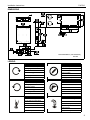
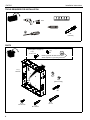
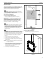
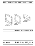
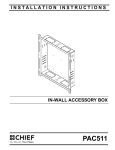
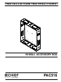
INSTALLATION INSTRUCTIONS
Instrucciones de instalación
Installationsanleitung
Instruções de Instalação
Istruzioni di installazione
Installatie-instructies
Instructions d´installation
IN-WALL ACCESSORY BOX
Spanish Product Description
German Product Description
Portuguese Product Description
Italian Product Description
Dutch Product Description
French Product Description
PAC516
PAC516
DISCLAIMER
Milestone AV Technologies, Inc., and its affiliated corporations
and subsidiaries (collectively, "Milestone"), intend to make this
manual accurate and complete. However, Milestone makes no
claim that the information contained herein covers all details,
conditions or variations, nor does it provide for every possible
contingency in connection with the installation or use of this
product. The information contained in this document is subject
to change without notice or obligation of any kind. Milestone
makes no representation of warranty, expressed or implied,
regarding the information contained herein. Milestone assumes
no responsibility for accuracy, completeness or sufficiency of
the information contained in this document.
Installation Instructions
IMPORTANT ! : SUITABLE FOR USE IN OTHER
ENVIRONMENTAL AIR SPACE IN ACCORDANCE
WITH SECTION 300.22, (C) OF THE NATIONAL
ELECTRICAL CODE.
NOTE: The equipment shall be installed and assembled by
qualified service personnel.
NOTE: Knockouts are provided for ease of installation. Any
unused knockouts that have been punched are to be
closed up with a metal plug.
NOTE: The maximum specified ambient temperature of the
cabinet system is 40o - 120oF (4o - 49oC).
NOTE: Spacings - Minimum spacings between the
Chief® is a registered trademark of Milestone AV Technologies.
All rights reserved.
IMPORTANT WARNINGS AND
CAUTIONS!
WARNING: A WARNING alerts you to the possibility of
serious injury or death if you do not follow the instructions.
CAUTION: A CAUTION alerts you to the possibility of
damage or destruction of equipment if you do not follow the
corresponding instructions.
WARNING: Failure to read, thoroughly understand, and
follow all instructions can result in serious personal injury,
damage to equipment, or voiding of factory warranty! It is the
installer’s responsibility to make sure all components are
properly assembled and installed using the instructions
provided.
CAUTION: This equipment must be installed and
assembled by qualified service personnel in accordance with
local building codes.
WARNING: Failure to provide adequate structural strength
for this accessory can result in serious personal injury or
damage to equipment! It is the installer’s responsibility to
make sure the structure to which this accessory is attached
can support the combined weight of the box and all
equipment not to exceed 10 lbs (4.5 kg).
2
Accessories and components and the housing for
Information Technology Communication Equipment
shall be maintained for safe operation of the equipment
when installed in accordance with the National Electric
Code, ANSI/NFPA 70-1999. Refer to communication
equipment manufacturer’s specifications for minimum
spacings.
NOTE: This In-Wall Cabinet System is for use with ITE or
Audio/Video equipment only.
Installation Instructions
PAC516
DIMENSIONS
MEASUREMENTS: [MILLIMETERS]
INCHES
LEGEND
Tighten Fastener
Pencil Mark
Apretar elemento de fijación
Marcar con lápiz
Befestigungsteil festziehen
Stiftmarkierung
Apertar fixador
Marcar com lápis
Serrare il fissaggio
Segno a matita
Bevestiging vastdraaien
Potloodmerkteken
Serrez les fixations
Marquage au crayon
Loosen Fastener
Drill Hole
Aflojar elemento de fijación
Perforar
Befestigungsteil lösen
Bohrloch
Desapertar fixador
Fazer furo
Allentare il fissaggio
Praticare un foro
Bevestiging losdraaien
Gat boren
Desserrez les fixations
Percez un trou
Phillips Screwdriver
Hex-Head Wrench
Destornillador Phillips
Llave de cabeza hexagonal
Kreuzschlitzschraubendreher
Sechskantschlüssel
Chave de fendas Phillips
Chave de cabeça sextavada
Cacciavite a stella
Chiave esagonale
Kruiskopschroevendraaier
Zeskantsleutel
Tournevis à pointe cruciforme
Clé à tête hexagonale
3
PAC516
Installation Instructions
TOOLS REQUIRED FOR INSTALLATION
3/16"
M4
(included)
PARTS
Grounding screw and washer installed at factory
(See Figure 4 on page 6.)
J (2)
H (2)
#10
10-32 x 3/8"
Earthing symbol IEC 60418 No. 5019
affixed adjacent to grounding terminal.
A (1)
PAC516
1
B (4)
1/4"
C (6)
[Wire Tie Clip]
2
D (1)
M4
E (8)
1/8-18 x 3/4"
4
G (4)
1/4" x 2"
F (4)
M7 x 40mm
Installation Instructions
PAC516
INSTALLATION
The PAC516 is intended for use in installations where the wall
surface has not been finished and the structure (studs) is
exposed. The PAC516 requires the wall be finished around the
opening of the box after the box has been installed.
PAC516
Cut Out Area
WARNING: IMPROPER INSTALLATION CAN RESULT
DEATH OR SERIOUS PERSONAL INJURY! This accessory
should be installed by qualified personnel.
PAC-516 Site Preparation
Locate and Prepare Mounting Site
1.
Identify a suitable wall location for the accessory.
IMPORTANT ! : The PAC516 is designed for in-wall
installation between two wood or steel studs, 16" on
center. Inadequate space will remain on each side
between studs for electrical wires/cables, plumbing,
ductwork, or insulation. Locate accordingly!
WARNING: ELECTRICAL SHOCK HAZARD! CUTTING
OR DRILLING INTO ELECTRICAL WIRES OR CABLES
CAN CAUSE DEATH OR SERIOUS PERSONAL INJURY!
ALWAYS make certain area behind mounting surfaces is free
of electrical wires and cables before cutting, drilling, or
installing fasteners.
Figure 1
WARNING: EXPLOSION AND FIRE HAZARD! CUTTING
OR DRILLING INTO GAS PLUMBING CAN CAUSE DEATH
OR SERIOUS PERSONAL INJURY! ALWAYS make certain
area behind mounting surfaces is free of gas, water, waste, or
any other plumbing before cutting, drilling, or installing
fasteners.
2.
Using a stud sensor, locate and mark studs.
3.
Center and level housing between marked studs.
4.
Using housing as a template, draw pencil line completely
around housing.
Accessory Box Installation
1.
Insert PAC516 (A) into opening. (See Figure 2)
NOTE: Housing is designed to fit between and directly against
two adjacent wall studs.
5.
Using a measuring tool, measure the marked area and
compare to the dimensions below. If measurements match,
continue to Step 6. If not, adjust markings to match
dimensions below. (See Figure 1)
6.
Cut drywall on outside edge of line and remove.
(A)
Figure 2
5
PAC516
Installation Instructions
WARNING: ELECTRICAL SHOCK HAZARD! CUTTING
DANGER: IMPROPER WIRING CAN LEAD TO DEATH
OR DRILLING INTO ELECTRICAL WIRES OR CABLES
CAN CAUSE DEATH OR SERIOUS PERSONAL INJURY!
ALWAYS make certain area behind mounting surfaces is free
of electrical wires and cables before cutting, drilling, or
installing fasteners.
2.
OR SEVERE PERSONAL INJURY! Grounding must be
installed by qualified personnel using a UL Recognized No.
12AWG Green and Yellow grounding wire connected to
grounding lug on mount.
Secure accessory box to studs by:
WOOD STUD:
1.
2.
Drill four 3/16" dia. pilot holes in studs at mounting
holes. (See Figure 3)
1
Install four M7 x 40mm Allen head connector screws
(F) into pilot holes using an M4 Allen head drill bit
(D). (See Figure 3)
2
STEEL STUD:
1.
Drill four 3/16" dia. pilot holes in studs at mounting
holes. (See Figure 3)
2.
Install four 1/4" countersunk finishing washers (B)
and four 1/4" x 2" Phillips flat head self drilling
screws (G) into pilot holes. (See Figure 3)
Typical
Grounding lug location
1
Figure 4
x4
Installing Accessories
Accessories can be mounted directly to the PAC516 by using
the mounting screws provided and the mounting holes
integrated into the box.
To mount an accessory:
2
(F) x 4
(B) x 4
(Steel Stud Only)
2
(G) x 4
(Steel Stud Only)
Figure 3
6
1.
Identify area within accessory box where accessory is to be
mounted.
2.
Align the mounting holes in accessory with mounting holes
in box.
3.
Secure accessory to box using Phillips screwdriver and as
many 1/8-18 x 3/4" mounting screws (E) as required. (See
Figure 5)
4.
Use the wire tie clips (C), as necessary, for cable
management. (See Figure 5)
Installation Instructions
PAC516
(C)
3
(E) (8 provided)
Figure 5
7
PAC516
Installation Instructions
USA/International
Europe
Chief Manufacturing, a products division
of Milestone AV Technologies
Asia Pacific
8807-002009 Rev00
2009 Milestone AV Technologies,
a Duchossois Group Company
www.chiefmfg.com
07/09
A
P
F
A
P
F
A
8401 Eagle Creek Parkway, Savage, MN 55378
800.582.6480 / 952.894.6280
877.894.6918 / 952.894.6918
Fellenoord 130 5611 ZB EINDHOVEN, The Netherlands
+31 (0)40 2668620
+31 (0)40 2668615
Room 24F, Block D, Lily YinDu International Building
LuoGang, BuJi Town, Shenzhen, CHINA.
P +86-755-8996 9226
F +86-755-8996 9217