1
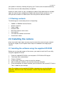
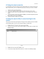
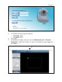
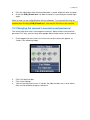
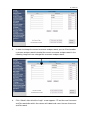
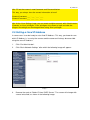
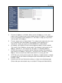
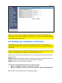
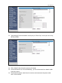
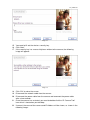
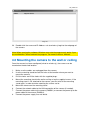
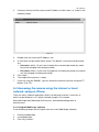
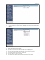
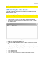
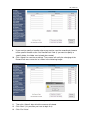
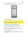
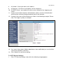
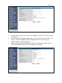
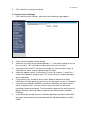
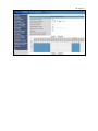
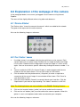
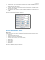
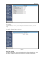
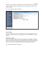
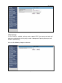
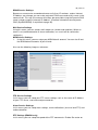
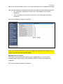
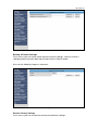
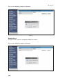
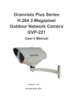
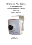
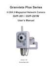
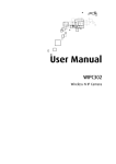
EM6561/EM6564 Wireless Internet Camera
2 | ENGLISH
EM6561/EM6564 – Wireless Internet Camera
Table of contents
1.0 Introduction................................................................................................................. 3
1.1 Functions and features .......................................................................................... 3
1.2 Packing contents.................................................................................................... 4
2.0 Installing the camera .................................................................................................. 4
2.1 Installing the software using the supplied CD-ROM ............................................. 4
2.2 Using the wired connection ................................................................................... 5
2.3 Using the search utility to connect and login to the camera................................. 5
2.4 Changing the camera’s username and password ................................................ 7
2.5 Setting a fixed IP-Address ..................................................................................... 9
3.0 Setting up a wireless connection ............................................................................. 11
3.1 Making a wireless connection manually.............................................................. 12
3.2 Making a wireless connection using the ‘Wireless Wizard Setup’ using the
supplied CD-ROM ...................................................................................................... 15
4.0 Mounting the camera to the wall or ceiling.............................................................. 18
5.0 Accessing the camera.............................................................................................. 19
5.1 Making the camera visible from the internet for a computer or mobile phone... 19
5.2 Accessing the camera externally (using the internet) using a computer ........... 22
5.3 Accessing the camera from the local network using a computer....................... 22
5.4 Accessing the camera using the internet or local network, using an iPhone .... 23
5.4.1 Using the Mobiscope software ...................................................................... 23
5.5 Accessing the camera using the internet or local network, using an iPad......... 24
5.5.1 Using the Mobiscope software ...................................................................... 24
5.6 Accessing the camera using the internet or local network, using a smartphone
with Android................................................................................................................ 25
5.6.1 Using the IP Cam Viewer software ............................................................... 25
5.7 Accessing the camera using the internet or local network, using a tablet with
Android ....................................................................................................................... 25
5.7.1 Using the IP Cam Viewer software ............................................................... 25
5.8 Accessing the camera using the internet or local network using a smartphone
with Windows Mobile 7 and up .................................................................................. 26
5.8.1 Using the IP CAM Controller software .......................................................... 26
5.9 Accessing the camera using the internet or local network using a mobile phone
with Symbian .............................................................................................................. 27
5.9.1 Installation of ‘IP Camera Player’ .................................................................. 27
5.9.2 Starting the ‘IP Camera Player’..................................................................... 27
5.10 Accessing the camera through the internet, using other mobiles phones with
the Windows Mobile, Java or Blackberry operating system ..................................... 28
5.11 Setting up Dynamic DNS ................................................................................... 28
6.0 Recording the video stream ..................................................................................... 31
7.0 Setting up an alarm notification ............................................................................... 33
7.1.1 Mail Service Settings ..................................................................................... 33
3 | ENGLISH
7.1.2 FTP Service Settings ..................................................................................... 35
7.1.3 Alarm Service Settings .................................................................................. 37
8.0 Explanation of the webpage of the camera............................................................. 39
8.1 ‘Device Status’ ..................................................................................................... 39
8.2 ‘For Visitor’ menu ................................................................................................. 39
8.3 ‘For Operator’ menu............................................................................................. 40
8.4 ‘For Administrator’ menu...................................................................................... 41
9.0 Frequently Asked Questions and other related information ................................... 50
10.0 Service and support ............................................................................................... 50
11.0 Warning and points of attention ............................................................................. 51
12.0 Warranty conditions ............................................................................................... 52
13.0 Declaration of Conformity ...................................................................................... 52
1.0 Introduction
Congratulations with the purchase of this high-quality Eminent product! This product
has undergone extensive testing by Eminent’s technical experts. Should you
experience any problems with this product, you are covered by a five-year Eminent
warranty. Please keep this manual and the receipt in a safe place.
Register your product now on www.eminent-online.com and receive product updates!
This manual is suitable for the following models:
•
First batch EM6561 (without R naming on the bottom label)
•
EM6561 R1
•
EM6564 R1
•
EM6564 R2
1.1 Functions and features
The Eminent EM6561/EM6564 IP-camera is an ideal solution for your surveillance
purposes. Thanks to the camera’s high resolution (640x480), the EM6561/EM6564 is
ideal to guard your belongings.
You can connect the camera to your wired network, but thanks to the wireless
interface, the camera can easily be added to your wireless network. With the
EM6564/EM6561, you won’t miss a thing!
The EM6561 has a Pan/Tilt functionality. Simply use the camera buttons on the
screen to move the camera from left to right and up and down. Nothing will be missed
by you! This camera also has infrared functionality. Very handy in dark environments!.
If you want to have far distance view, the EM6058 IR light is recommended.
The EM6564 is weatherproof and therefore ideal to use outside. Mount the camera to
an outside wall or a fence and connect wirelessly to your network. Keep a close eye to
4 | ENGLISH
your garden or driveway. Nothing will get by you! Thanks to the infrared functionality,
the camera can also be used perfectly at nighttime.
Watch live video stream on your smartphone or tablet! Simply download an available
app in the store of your smartphone or tablet and connect to your camera(‘s). It is
even possible to watch live video stream from everywhere around the world!
1.2 Packing contents
The following parts need to be present in the packing:
•
•
•
•
•
•
•
•
EM6561 or EM6564 Internet Camera
Wireless antenna
Power supply
Network cable
Mounting materials with screws
User manual
CD-ROM with software and wizard
Surveillance sticker
2.0 Installing the camera
A few short and simple steps are necessary to connect the camera to your network.
During this chapter, we will explain which steps are needed to start enjoying the
camera.
2.1 Installing the software using the supplied CD-ROM
Before you can view the images of the camera, you need to install the IP-cam utility
using the supplied CD-ROM:
1.
2.
3.
4.
5.
6.
Place the supplied CD-ROM in your computer’s CD-ROM or DVD-player.
The wizard starts automatically.
Choose ‘Software’
Use the steps shown on screen to install the software.
After installing the software, you need to restart your computer.
Once the computer has been restarted, you will notice an icon named‘ IP Camera
Tool’ is added to your desktop.
Note: The software on the supplied CD-ROM is intended to be used for Windows
computers. Macintosh users may download a search utility from www.eminentonline.com
5 | ENGLISH
2.2 Using the wired connection
It is advisable to connect the camera to your wired network first. Once the camera has
been setup correctly, you can setup the camera to be used for your wireless network.
1.
2.
3.
4.
5.
Take the camera out of the packing.
Connect the supplied network cable to the LAN connection of the camera.
Connect the other side of the network cable to a free LAN port of your router or
switch.
Connect the power cable to the camera (EM6561) or connect the power tip to the
power cable of the camera (EM6564).
Connect the power supply to a wall outlet.
2.3 Using the search utility to connect and login to the
camera
The camera can be accessed using the ‘IP Camera Tool’ software you have installed.
In the following steps, we will assume Internet Explorer is being used.
1.
2.
Double-click the ‘IP Camera Tool’ icon on your desktop.
If correct, the name of the camera and IP-Address will be shown as shown in the
following image:
Image 1
3.
4.
Double-click the name and IP-Address rule.
A username and password will be asked as is shown in the following image:
6 | ENGLISH
Image 2
5.
6.
7.
The default username and password are:
•
Username: admin
•
Password: admin
Click ‘Login’.
A notification will appear which tells you the ‘DVM_IPcam2.ocx’ of ‘Eminent
Europe B.V.’ needs to be installed, as shown in the following image (logged in to
the EM6561):
Image 3
7 | ENGLISH
8.
9.
Click the notification after which conformation is asked. Allow this to be installed.
Once the ‘DVM_IPcam2.ocx’ has been installed, it is possible you need to login
again.
Note: In case you are using Windows Vista or Windows 7, your permission may be
needed when installing ‘DVM_IPcam2.ocx’. You need to allow this to be installed.
2.4 Changing the camera’s username and password
The safest thing to do next is to change the camera’s Administrator username and
password. This way, you can deny other people Administrator access to the camera.
1.
Once logged in to the camera, the main menu of the camera will appear, as
shown in the following image:
Image 4
2.
3.
4.
Click ‘For Administrator’.
Click ‘User Settings’.
You will see the current users. If correct, the Administrator user is also shown.
Also see the following image as reference:
8 | ENGLISH
Image 5
5.
In order to change the current username and password, you can fill out another
username and password instead of the current username and password. In the
following image we have changed the username and password:
Image 6
6.
Click ‘Submit’ after which the ‘Login’ screen appears. Fill out the new Username
and Password after which the camera will reboot and saves the new Username
and Password.
9 | ENGLISH
Hint: Fill out the camera’s new Username and Password below.
This way, you always have the correct information at hand!
Camera Username: ___ . ___ . ___ . ___
Camera Password: ___ . ___ . ___ . ___
Hint: At the ‘User Settings’ page, you can create multiple accounts with ‘Administrator’,
‘Operator’ or ‘User’ privileges. ‘User’ privileges only allows to login and view the
images. No settings can be changed when using ‘User’ privileges.
2.5 Setting a fixed IP-Address
In some cases it can be handy to set a fixed IP-Address. This way, you know for sure
which IP-Address is in use by the camera and the camera will always be accessible
using the same IP-Address.
1.
2.
Click ‘For Administrator’.
Click ‘Basic Network Settings’ after which the following image will appear:
Image 7
3.
Remove the mark at ‘Obtain IP from DHCP Server’. The screen will change with
several extra field, as shown in the following image:
10 | ENGLISH
Image 8
4.
5.
6.
7.
8.
9.
Fill out an IP-Address at ‘IP Addr’. Make sure this IP-Address is in the same
range as the IP-range of your current network and this IP-Address is not already
in use. For example: If your network has a ‘192.168.8.x’ range, you may fill out
‘192.168.8.54’ as IP-Address.
Fill out a subnet mask at ‘Subnet Mask’. This subnet mask needs to be the same
as is used within your own network. For example: If your network has a
‘192.168.8.x’ range, you may fill out ‘255.255.255.0’ as ‘Subnet Mask’.
At ‘Gateway’ you need to fill out the correct gateway-address of your network.
This usually is the IP-Address of your router. For example: If your router has IPAddress ‘192.168.8.1’, you may fill out ‘192.168.8.1’ as Gateway Address.
At ‘DNS Server’ you can usually fill out the ‘Gateway’ number. For example: If
your router has IP-Address ‘192.168.8.1’, you may fill out ‘192.168.8.1’ as DNS
Address. You can also fill out a DNS server which is in use by your ISP.
‘HTTP Port’ can usually remain at port ‘80’. However, if another device is already
using port 80, you can choose to change this port with another port number. For
Example: ‘8080’.
If correct, you will have filled out the settings as shown in the following image:
(Please note your own network may use another IP-Range and Subnet Mask)
11 | ENGLISH
Image 9
Note: If the ‘HTTP Port’ is changed, it means this port needs to be forwarded to be
able to access the camera externally. In chapter 5.1 you need to forward the changed
port number instead of port ‘80’.
3.0 Setting up a wireless connection
Note: Make sure you have all the necessary data at hand such as your wireless
network name (SSID) and the wireless security key before you start with the wireless
connection!
Note: In order to be able to connect the camera wirelessly, you need to make sure the
camera is connected to your network using the wired connection.
Before the camera can be connected wirelessly, the antenna needs to be connected
to the camera:
EM6564 camera: Hold the antenna with 2 fingers and turn the six-sided nut clockwise.
In order to lock the six-side nut, you may use a wrench (number 8).
EM6561 camera: Turn the antenna clockwise.
The camera can be connected wirelessly using two manners:
•
Manner 1: Making a wireless connection manually.
•
Manner 2: Making a wireless connection using the ‘Wireless Wizard Setup’.
Both manners will be explained in the following chapter:
12 | ENGLISH
3.1 Making a wireless connection manually
1.
2.
Double-click the ‘IP Camera Tool’ icon on your desktop.
If correct, the name of the camera and IP-Address will be shown as shown in the
following image:
Image 10
3.
4.
5.
6.
Double-click the name and IP-Address rule.
Log in to the webpage of the camera.
Click ‘For Administrator’.
Click ‘Wireless LAN Settings’ after which the following image is shown:
Image 11
13 | ENGLISH
7.
8.
9.
Place a mark at ‘Using Wireless LAN Settings’
Click ‘Scan’ after which the camera will search for wireless networks within reach.
If correct, the SSID of your own wireless network will appear at the ‘Wireless
Network List’ (Sometimes, you need to scan for the second time to see SSID’s)
as shown in the following image:
Image 12
10. Click the correct SSID.
11. If your network has been secured, the correct security type will automatically be
shown. If this is not the case, you need to select the correct security type from
the list.
12. You need to fill out the network security key at ‘KEY 1,2,3 or 4’ in case you are
using WEP security as shown in the following image:
14 | ENGLISH
Image 13
13. You need to fill out the network security key at ‘Share Key’ in case you are using
WPA or WPA2.
Image 14
14. Click ‘Submit’ after which the camera will reboot.
15. Once the camera has finished rebooting , you can disconnect the network cable
from the camera.
16. Disconnect the power cable from the camera and reconnect the power cable
after a few seconds.
15 | ENGLISH
17. Once the camera has restarted, you need to double-click the ‘IP Camera Tool’
icon which is located on your desktop.
18. If correct, the name of the camera and IP-Address will be shown, as shown in the
following image:
Image 15
19. Double-click the name and IP-Address rule to wirelessly login to the webpage of
the camera.
3.2 Making a wireless connection using the ‘Wireless
Wizard Setup’ using the supplied CD-ROM
1.
2.
3.
4.
5.
6.
7.
8.
9.
Place the supplied CD-ROM in your computer’s CD-ROM or DVD-player.
The wizard starts automatically.
Choose ‘Wizard for Wireless connection’.
Click ‘Next’.
An image will be shown telling you how to connect the camera to the power
supply.
Click ‘Next’.
Another image will be shown telling you how to connect the network cable.
Click ‘Next’.
If correct, the IP-Address, Name and Mac-Address of the camera will be shown
as shown in the following example:
16 | ENGLISH
Image 16
10. Click the IP-Address rule and click ‘Next’.
11. The software will start searching for wireless networks within range.
12. If correct, the SSID of your wireless network will be visible, as shown in the
following image:
Image 17
13. Click the correct SSID and click ‘Next’.
14. If your network has been secured, the correct security type will automatically be
shown, as shown in the following image:
17 | ENGLISH
Image 18
15. You need to fill out the wireless security key.
16. Click ‘Next’.
17. If the security key has successfully been written to the camera, the following
image will appear:
Image 19
18. Click ‘Exit’ to close the screen.
19. Disconnect the network cable from the camera.
20. Disconnect the power cable from the camera and reconnect the power cable
after a few seconds.
21. Once the camera has restarted, you need to double-click the ‘IP Camera Tool’
icon which is located on your desktop.
22. If correct, the name of the camera and IP-Address will be shown, as shown in the
following image:
18 | ENGLISH
Image 20
23. Double-click the name and IP-Address rule to wirelessly login to the webpage of
the camera.
Note: When opening the software, Windows may note the program only works if you
let the Windows Firewall unblock the program. You need to choose ‘Unblock’.
4.0 Mounting the camera to the wall or ceiling
Once the camera has been configured (wired or wirelessly), the camera can be
mounted on the desired location.
1.
2.
3.
4.
5.
6.
7.
8.
Make sure the cables are unplugged from the camera.
Use the mounting stand to mark the holes at the location where you want to
mount the camera.
Drill the holes and fill the holes with the supplied plugs.
Mount the mounting stand to the wall or ceiling using the supplied screws. If the
mounting stand is still attached to the camera, you can twist off the mounting
stand again, in order to make mounting the screws easier.
Mount the camera on the mounting stand.
Connect the network cable to the LAN connection of the camera (if needed).
Connect the power cable to the camera (EM6561) or connect the power tip to the
power cable of the camera (EM6564).
Connect the power supply to a wall outlet.
19 | ENGLISH
5.0 Accessing the camera
5.1 Making the camera visible from the internet for a
computer or mobile phone
Before you can view the images of the camera using the internet, you need to open
port 80 in your router and forward this port to the IP address of your camera. In the
example below, we explain how you can configure your
EM4570/EM4542/EM4551/EM4553 router. During the following chapter, we are using
the EM4570 Wireless N-router.
Note: If you are using another type or brand of router, you need to refer to the manual
of your router for more information about opening Ports.
1.
2.
Double click the ‘IP Camera Tool’ shortcut placed on your desktop.
The program will automatically search for your camera in your network. When
found, the camera will be displayed in the list, as shown in the following image:
Image 21
3.
4.
5.
6.
•
•
7.
Write down the IP Address of your camera. (For example: 192.168.8.54).
Close the program.
Now open the webpage of your router by opening your web browser and filling
out the router’s IP Address in the address bar, in this case: http://192.168.8.1.
Login using the router’s username and password. The EM4570’s default
username and password are:
Username: admin
Password: admin
The main page of the router will be shown, as shown in the following image:
20 | ENGLISH
Image 22
8.
Click ‘Setup Tool’ after which the following image appears:
Image 23
9. Click ‘Advanced Setup’.
10. Click ‘NAT/Routing’.
11. Click ‘Port Forwarding’ after which the following image will appear:
21 | ENGLISH
Image 24
12. Fill out ‘Camera’ in the ‘Rule Name’ field.
13. Fill out the camera’s IP-Address in the LAN IP address’ field, for example:
‘192.168.8.54’.
14. Select the ‘TCP’ option at ‘Protocol’.
15. Fill out ‘80’ at both ‘External Ports’ fields.
(If port 80 is already in use, you can also use another port, for example: 8080.
But you need to change this port also in your camera then).
16. Fill out ‘80’ at both ‘Internal Ports’ fields, unless you have changed this port in the
camera itself. (at the ‘LAN’ page). If correct, you have filled out the settings as
shown in the following screen:
22 | ENGLISH
Image 25
17. Click ‘Add’, after which the new rule will be added to the list.
18. Click ‘Save’ to save the settings.
19. The port forwarding has now been finished. Your camera is now accessible
externally for third parties (Or by yourself if you want to connect to the camera
externally). The camera is accessible on the internet IP-Address or by using your
dynamic DNS name. (More information about dynamic DNS (DynDNS/DDNS) is
explained in chapter 5.11 on page 28).
Hint: You can find the Internet IP-Address by opening your web browser and typing:
www.eminent-online.com/ip
Hint: Fill out the camera’s (local) IP-Address and internet IP-Address below.
This way, you always have the correct information at hand!
Camera IP-Address: ___ . ___ . ___ . ___
Internet IP-Address: ___ . ___ . ___ . ___
5.2 Accessing the camera externally (using the internet)
using a computer
1.
2.
3.
4.
5.
6.
Open your web browser (Internet Explorer) and fill out: http://external.ip.addr.ess
(for example: http://84.12.98.15).
If you have not set port number 80 at step 14, but another port number, you have
to fill out this port number. For example, If you have set port number 8080, you
have to fill out: http://external.ip.addr.ess:8080 or http://camera.dyndns.org:8080.
A username and password will be asked. The default* username and password
are:
•
Username: admin (*If you have changed the username/password you need
to use the changed username/password)
•
Password: admin (*If you have changed the username/password you need
to use the changed username/password)
Click ‘Login’.
The image of the camera is shown.
If you are using the EM6561, you can control the camera’s position using the PT
buttons (Pan Tilt).
5.3 Accessing the camera from the local network using a
computer
The camera can be accessed from the local network using the following steps:
1.
Double-click the ‘IP Camera Tool’ icon which is located on your desktop.
23 | ENGLISH
2.
If correct, the name of the camera and IP-Address will be shown, as shown in the
following image:
Image 26
3.
4.
5.
6.
7.
Double-click the name and IP-Address rule.
A username and password will be asked. The default* username and password
are:
• Username: admin (*If you have changed the username/password you need
to use the changed username/password)
• Password: admin (*If you have changed the username/password you need to
use the changed username/password)
Click ‘Login’.
The image of the camera is shown.
If you are using the EM6561, you can control the camera’s position using the PT
buttons (Pan Tilt).
5.4 Accessing the camera using the internet or local
network, using an iPhone
There are many software applications which can be purchased for a small fee, or
which can be tested for 1 or 2 weeks (without charge). For example:
www.mobiscope.com/download (Paid version), www.totalcontrolapp.com or
www.ttrix.com.
5.4.1 Using the Mobiscope software
In the following example we will explain how to use the MobiScope software.
1.
2.
3.
Purchase Mobiscope.
Install Mobiscope.
Click ‘My Cameras’.
24 | ENGLISH
4.
5.
6.
7.
8.
Click on the ‘+’ button (add camera).
Enter the network address, port, username and password of the camera.
Click ‘test’ to test the camera.
Click ‘Save’ to save the camera settings.
You can now view the camera by clicking on the camera name.
5.5 Accessing the camera using the internet or local
network, using an iPad
In the following example we are using an iPad3 with IOS 5.1. We will describe the use
of Mobiscope, which is a paid service.
5.5.1 Using the Mobiscope software
In the following example we will explain how to use the MobiScope software.
1.
2.
3.
4.
5.
6.
7.
8.
9.
10.
11.
12.
13.
14.
15.
16.
17.
18.
19.
20.
21.
22.
23.
24.
25.
Enter the Apple Appstore.
Search for the ‘Mobiscope’ app and purchase this app.
Install the ‘Mobiscope’ app.
Open the ‘Mobiscope’ software.
Press the ‘+’ sign.
Press ‘Network camera’.
Press the ‘Add network address’ tab.
Fill out the IP-Address of the camera at ‘IP address or hostname’.
Fill out the http port number of the camera at ‘TCP port number’. In this case
the port number is ‘80’, unless you have changed the http port number of
the camera. If so, you have to use the changed port number.
Press the ‘Done’ tab.
Press the ‘Add camera model’ tab.
Choose the brand (Eminent) and select the camera type. At the moment of
writing the manual, only the EM6561 (PTZ) is selectable.
Press the ‘Done’ tab.
Press the ‘Authorization’ tab and set the slider to ‘On’.
Fill out the username of the camera at the ‘Login’ field.
Fill out the password of the camera at the ‘Password’ field.
Press the ‘Done’ tab.
If you want to fill out a name for the camera, you need to press the ‘Add
camera name’ tab.
Fill out a name for the camera at the ‘Camera name’ field.
Press the ‘Done’ tab.
If you want to add the camera to a group, you need to press the ‘Add
camera to group’ tab.
Fill out the name of the group at the ‘New group name’ field.
Press the ‘Done’ tab.
Press the ‘Save’ tab to save the settings.
If correct, the name of the camera will be shown in the following screen. By
25 | ENGLISH
pressing the name tab, the image of the camera will be shown.
Hint: The Mobiscope version we have been using with the iPad is version 1.15.
Although the EM6564 is not in the list with camera types, you can select EM6561 PTZ
to be able to use the EM6564. All settings will work, except the PTZ setting since the
EM6564 is not a PTZ camera.
Hint: There are also some free software versions of IP Cam viewers. However, in most
cases you need to register at the manufacturer’s website to be able to use the
software. Examples of free software: CamViewer, IPCamPal Lite and EasyCam.
5.6 Accessing the camera using the internet or local
network, using a smartphone with Android
5.6.1 Using the IP Cam Viewer software
1. Go to ‘the ‘Play Store’.
2. Search ‘for the application ‘IP Cam Viewer Lite’.
3. Install this application.
4. Start the application ‘IP Cam Viewer Lite’.
5. Press the ‘+’ button (add camera).
6. Select the camera type, in this case ‘IP Camera, DVR, NVR’.
7. Fill out a name for the camera. For Example: ‘Camera 1’.
8. Select the make (brand). Choose ‘Eminent’.
9. Select the camera model. Choose ‘EM6564’.
10. Fill out the IP-Address of the camera at ‘Hostname or IP’.
11. Fill out the HTTP port. In this case, port ‘80’ needs to filled out (unless you have
changed this port number. In that case you need to fill out the changed port
number).
12. Fill out the username and password of the camera at the ‘User’ and ‘Pswd’ field.
13. Click ‘Test’ to test the connection.
14. If the test is successful, you need to click ‘Save’.
15. If the IP Cam Viewer software is started again, the camera can be accessed.
Hint: The IP Cam Viewer version we have been using is version 4.4.6.3. Only the
EM6564 is selectable from the list of camera models. However, the EM6564 type can
also be chosen for the EM6561 with PTZ functions.
5.7 Accessing the camera using the internet or local
network, using a tablet with Android
In the following steps, we are using a Galaxy Tab 10.1:
5.7.1 Using the IP Cam Viewer software
1. Go to ‘the ‘Play Store’.
2. Search ‘for the application ‘IP Cam Viewer Lite’.
26 | ENGLISH
3.
4.
5.
6.
7.
8.
9.
10.
11.
12.
13.
14.
15.
16.
Install this application.
Start the application ‘IP Cam Viewer Lite’.
It is possible a list will be shown with the changes in this IP Cam Viewer Lite
version.
Press the ‘+’ button (add camera).
Select the camera type, in this case ‘IP Camera, DVR, NVR’.
Fill out a name for the camera. For Example: ‘Camera 1’.
Select the make (brand). Choose ‘Eminent’.
Select the camera model. Choose ‘EM6564’.
Fill out the local IP-Address of the camera at ‘Hostname or IP’ when you want to
connect to the camera using the local network. Fill out the internet IP-Address if
you want to connect to the camera externally.
Fill out the HTTP port. In this case, port ‘80’ needs to filled out (unless you have
changed this port number. In that case you need to fill out the changed port
number).
Fill out the username and password of the camera.
Click ‘Test’ to test the connection.
If the test is successful, you need to click ‘Save’.
If the IP Cam Viewer software is started again, the camera can be accessed.
Hint: The IP Cam Viewer version we have been using is version 4.4.6.3. Only the
EM6564 is selectable from the list of camera models. However, the EM6564 type can
also be chosen for the EM6561 with PTZ functions.
5.8 Accessing the camera using the internet or local
network using a smartphone with Windows Mobile 7 and
up
In the following example, we are using a Nokia Lumia smart phone with Windows 7.5
(Mango) as operating system.
5.8.1 Using the IP CAM Controller software
1. Go to ‘http://www.wpmangoapps.com’.
2. Search for the ‘IP CAM Controller’ app.
3. Install this application.
4. Start the application’.
5. Press the ‘new camera’ button’.
6. Fill out a name for the camera. For Example: ‘Camera 1‘.
7. Fill out the IP-Address of the camera.
8. If the brand or type is asked, you can select ‘Eminent’. If Eminent is not present,
you can choose ‘Foscam’.
9. Fill out the correct ‘HTTP’ port. In this case, port ‘80’ needs to filled out (unless
you have changed this port number. In that case you need to fill out the changed
port number).
10. Fill out the username and password of the camera.
27 | ENGLISH
11. Press the ‘Save’ button to save these settings.
12. If the IP Cam Controller software is started again, the camera can be accessed.
5.9 Accessing the camera using the internet or local
network using a mobile phone with Symbian
In the following example, we are using a Nokia N97 mini. Other phones with the
Symbian Operating system might have slightly different steps.
5.9.1 Installation of ‘IP Camera Player’
1. Click on the menu button.
2. Open the webbrowser.
3. Click on 'options'.
4. Click 'Go to'.
5. Click 'New web page'.
6. Fill out: http://www.eminent-online.com/EM6564/ipcam.jar and click on the enterkey.
7. The following notification appears: 'Install IP Camera Player’.
8. Click ‘OK’.
9. The telephone might give a security warning. Click 'Continue'.
10. Select the location/drive where the files can be stored.
We suggest to choose 'C: Phone mem.'
11. Click 'Select'.
12. The notification 'Installation complete' appears.
13. Click 'Close'.
5.9.2 Starting the ‘IP Camera Player’
1. Click the menu button.
2. Click 'Applications'.
3. Select the application 'IP Camera Player' and click the 'enter' button.
4. You can leave the ‘Alias’ field empty.
5. Fill out the IP-Address of the camera in the field ‘Camera Hostname/IP’
(normally without the text ‘http://’).
6. Fill out the port of the camera in the field ‘Port’. Often port 80 is used, sometimes
port 81 or 8080.
7. Fill out the username ‘admin’ in the field ‘User’.
8. Fill out the password ‘admin’ in the field ‘Password’.
9. Click 'Options'.
10. Click 'OK'.
11. If the telephone show the notification: 'Allow application to use network?' then
click 'Allow for this session'.
12. The telephone will notify after a few seconds: 'Connecting to camera...'
13. The image of the camera will be shown.
28 | ENGLISH
5.10 Accessing the camera through the internet, using
other mobiles phones with the Windows Mobile, Java or
Blackberry operating system
There are 3 solutions to view video images on your mobile phone with the Windows
Mobile, Java or Blackberry operating system.
1. Copy the Java software ‘IPCamera.jar’ from the CD-ROM to your mobile phone and
install this application on your mobile phone.
Open your Java application and run the program ‘IP Camera Player’.
Please be noted this Java software is not supported by certain mobile phones, even if
these phones support Java.
2. You can also view a live ‘photo’ of the camera by opening the browser on your
mobile phone and adding the following url as favorite link:
http://192.168.8.xxx/snapshot.cgi?user=admin&pwd=admin
In above textline, you need to replace 192.168.1.xxx by the public IP address of your
ipcamera when viewing through the internet. (or fill out the local IP address when
viewing in your local network).
This is not live video, but 1 image at a time. This image can be refreshed in your
browser by using the ‘refresh’ feature of your browser.
3. If you need more features, you can try third-party software such from:
www.mobiscope.com or www.totalcontrolapp.com. After 1 or 2 weeks, you will have to
pay for this software if you want to keep using this software.
Since there are countless types of mobile phones and smart phones, Eminent can not
guarantee the working of the described programs. If problems do occur, you need tom
refer to the manufacturer of the software.
5.11 Setting up Dynamic DNS
Because a name can be remembered more easily than IP-numbers, and an Internet
IP-Address can change, you can make a dynamic DNS name and set this name in the
camera itself. This way, the camera will always be accessible using the Dynamic DNS
name instead using the (Internet) IP-Address.
Attention! If you have already set a dynamic DNS name in your wireless router, there
is no need to set this name again in the camera.
For Example: You can make an account by using www.dyndns.org or www.no-ip.com
You will then receive a dynamic DNS name, a username and a password for your
connection.
29 | ENGLISH
Note: DynDNS has previously been a free service. However, at this moment DynDNS
is a paid service.
Note: In order to be able to use www.no-ip.com in the camera, the camera needs to
have the latest firmware installed. Check www.eminent-online.com if the latest
firmware is already installed in your camera.
Use the following settings to setup the camera:
1.
2.
Double-click the ‘IP Camera Tool’ icon which is located on your desktop.
If correct, the name of the camera and IP-Address will be shown, as shown in
the following image:
Image 27
3.
4.
5.
6.
7.
Double-click the name and IP-Address rule.
A username and password will be asked. The default* username and password
are:
• Username: admin (*If you have changed the username/password you need
to use the changed username/password)
• Password: admin (*If you have changed the username/password you need to
use the changed username/password)
Click ‘Login’.
Click ‘For Administrator’
Click ‘DDNS Service Settings’ after which the following image will appear:
30 | ENGLISH
Image 28
8.
Click the arrow at the ‘DDNS Service’ dropdown list after which the following list
appears:
Image 29
9.
10.
11.
12.
13.
14.
Select your DDNS Service provider.
Fill out the username of your dynamic DNS name at ‘DDNS User’.
Fill out the password of your dynamic DNS name at ‘DDNS Password’.
Fill out your dynamic DNS name at ‘DDNS Host’.
Click on ‘Submit’ to save the settings.
Your camera can now be accessed with your dynamic DNS name!
31 | ENGLISH
Note: The correct port must have been forwarded to your camera to be able to access
the camera using the DDNS function!
6.0 Recording the video stream
It is possible to record the video stream of the camera. Use the following steps to
record the camera’s images:
Note: If you are using Internet Explorer, you will be able to view and record from 16
camera’s simultaneously. Other web browsers such as using Firefox or Chrome will
only be able to record from one camera.
1.
2.
Double-click the ‘IP Camera Tool’ icon which is located on your desktop.
If correct, the name of the camera and IP-Address will be shown, as shown in
the following image:
Image 30
3.
4.
5.
6.
7.
8.
Double-click the name and IP-Address rule.
A username and password will be asked. The default* username and password
are:
• Username: admin (*If you have changed the username/password you need
to use the changed username/password)
• Password: admin (*If you have changed the username/password you need to
use the changed username/password)
Click ‘Login’.
Click ‘For Administrator’
Click ‘For Administrator’.
Click ‘User Settings’, after which the following image will be displayed:
32 | ENGLISH
Image 31
9.
If you want to specify a location where you want to save the recording to, browse
to the specific location at the ‘Set Record Path’ field. (If you want to specify a
specific folder, the folder must already be created).
10. Click ‘Submit’ to save these settings. The camera will notify the changing of the
Record Path was successful as shown in the following image:
Image 32
11. Then click ‘Submit’ after which the camera will reboot.
12. Click ‘Back’ (It is possible you have to login first).
13. Click ‘For Visitor’.
33 | ENGLISH
14. Select the camera you want to record from (the camera(s) which are available
will only be selectable at the numbers ‘1’ till ‘9’.
15. Click the ‘camera’ icon to start recording as shown in the following image:
Image 33
16. If you have set a specific recording folder at step 4, the recorded files will be
stored in the specified folder.
Note: You can also record images when logged in externally (Using the internet).
Hint: The recorded files are stored as AVI files. Almost every media player such as
Windows Media Player is able to play these types of files.
7.0 Setting up an alarm notification
The camera also has the possibility to generate alarm notifications. You can setup the
camera to generate an alarm notification in case motion is detected.
During the following steps we will explain how to setup the camera for an alarm
notification by e-mail and FTP. We need to setup the mail settings and FTP settings
first before setting up the motion detect alarm.
7.1.1 Mail Service Settings
1. Double-click the ‘IP Camera Tool’ icon which is located on your desktop.
2. If correct, the name of the camera and IP-Address will be shown, as shown in the
following image:
34 | ENGLISH
Image 34
3.
4.
5.
6.
7.
Double-click the name and IP-Address rule.
A username and password will be asked. The default* username and password
are:
• Username: admin (*If you have changed the username/password you need
to use the changed username/password)
• Password: admin (*If you have changed the username/password you need to
use the changed username/password)
Click ‘Login’.
Click ‘For Administrator’
Click ‘Mail Service Settings’ after which the following image appears:
Image 35
35 | ENGLISH
8. At ‘Sender’, fill out your own e-mail address.
9. At ‘Receiver’, fill out the e-mail address of the recipient(s).
10. At ‘SMTP Server’, you need to fill out the server settings of the ‘outgoing mail
server’.
11. If your e-mail account requires authentication, place a mark at ‘Authentication’
and fill out the username and password of your e-mail account.
12. If correct, the screen will be filled out as shown in the following example. Please
note: The image is purely an example:
Image 36
13. If an ‘event’ takes place, (Motion detection or alarm notification) an e-mail will be
send to the recipients (receivers).
14. Click ‘Submit’ to save these settings.
7.1.2 FTP Service Settings
1. Click ‘FTP Service Settings’ after which the following image appears:
36 | ENGLISH
Image 37
2.
3.
4.
Fill out the data of your FTP server (The IP-Address of your FTP server, the port
number etc).
If a mark is placed at ‘Upload Image Now’, you can set an interval. Choose a ‘10
seconds’ interval to upload a camera image to your FTP server every ten
seconds when an event takes place.
If correct, the screen will be filled out as shown in the following image. Please
note: The following image is purely intended as an example:
Image 38
37 | ENGLISH
5.
Click ‘Submit’ to save these settings.
7.1.3 Alarm Service Settings
1. Click ‘Alarm Service Settings’, after which the following image appears:
Image 39
2.
3.
4.
5.
6.
7.
8.
Place a mark at ‘Motion Detect Armed’.
Select the sensitivity of the motion detection. ‘1’ is the lowest setting and is the
least sensitive, ‘10’ is the highest setting and is the most sensitive.
Since the E-mail and FTP services are already set, you can place a mark at
‘Send Mail on Alarm’ and at ‘Upload Image on Alarm’.
Select the upload interval. If the camera is set to ’10 seconds’, it means the
camera will upload an image to your FTP server every ten seconds during an
alarm notification.
If you want to set a schedule, which means Motion Detection and alarm
notifications will take place at preset times, you can place a mark at ‘Scheduler’.
If you want to set Motion Detection and alarm notifications during the whole
week, at specific times, you can select the days and times on which the
recordings needs to take place. The blue colours represent the active hours of
Motion Detection, the white colours represent the inactive hours of Motion
Detection.
In the following example we have set Motion detection and alarm notifications
during the whole week, but only between 00:00 - 08:00 and between 18:00 –
22:00.
38 | ENGLISH
Image 40
39 | ENGLISH
8.0 Explanation of the webpage of the camera
In the paragraph below, we assume you logged in to the camera using Internet
Explorer.
The menu will be slightly different when using other web browsers.
8.1 ‘Device Status’
The ‘Device status’ shows the amount of camera’s which are added to the network.
The green circle represents the active camera.
Also see the following image as reference:
Image 41
8.2 ‘For Visitor’ menu
1.
2.
3.
4.
If multiple camera’s are added, click the plane with four or nine squares. Each
square represents a camera image. Double-click an image to display the image
in full screen. Double-click the image again to view the image in a small screen
again. You can also select a specific camera by clicking the camera number ‘1’ to
‘9’.
You can enable the OSD (On Screen Display) in order the date and time are
shown on the live video stream. You can also select an OSD colour.
Click the button with the photo camera (‘Snapshot’) to make a snapshot or
screenshot of the current image. A new window will be shown. Click ‘Save’ to
save the photo as a file.
Click the camera button (‘Record’) to record video to your hard disc. Click the
‘Stop’ button if you want to stop recording. The video is stored as an AVI file.
Note: The following features are only available on the EM6561 Rotating Camera:
5.
6.
Click on the ‘headset’ button (‘audio’) to listen to audio from the camera.
Click on the ‘mic’ button (‘talk’) to send audio to the camera speaker. When this
option is used, a microphone needs to be connected to your computer.
Also see the following image as reference:
40 | ENGLISH
Image 42
Note: The audio features of the EM6561 camera are just for surveillance use, and not
for a high quality ‘phone’ conversation.
If you want to talk using the camera, make sure the microphone option is enabled in
the mixer of your sound card.
8.3 ‘For Operator’ menu
1.
2.
3.
For EM6561 only: Use the arrows to move the camera up/down and left/right.
Click ‘Flip’ to rotate the image. This is a handy feature, in case the camera is
mounted to a ceiling and is situated up-side-down. If ‘Flip’ is chosen, the
camera’s image will be shown up-side-down so the camera’s image will appear
‘normal’.
Click ‘Mirror’ to display the image mirrored.
Also refer to the following image as reference to the PTZ functions:
Image 43
41 | ENGLISH
4.
5.
6.
At ‘Resolution’, you can change the resolution of the image. 640x480 delivers the
highest possible image quality.
At ‘Mode’, you can set the environment setting. If the camera is ‘looking’ outside,
you can select ‘Outdoor’.
At ‘Brightness’ and ‘Contrast’, you can change the brightness and contrast of the
image.
Also refer to the following image for reference:
Image 44
8.4 ‘For Administrator’ menu
Device Info
In the ‘Device Info’ menu, you will find detailed information about the camera such as:
•
Device ID.
•
The current firmware version.
•
Software version of the web interface.
•
The Alias of the camera (name of the camera).
•
Alarm status.
•
DDNS Status.
•
UPnP Status.
•
MSN Status.
Also see the following image are reference:
42 | ENGLISH
Image 45
Alias Settings
In the ‘Alias Settings’ menu, you can change the name of the camera to your own
liking.
Also see the following image as reference:
Image 46
Data &Time Settings
At ‘Date & Time Settings’, you can set the date and time. When setting the time, make
sure you are using the correct time zone and use the ‘Daylight Saving’ feature if
43 | ENGLISH
needed. If you are located in the Netherlands, you should select ‘Brussel, Paris, Berlin
etc’ as ‘Timezone’. Activate ‘Daylight Saving Time’ and select ‘60’ at ‘Advance Time’
and click ‘Submit’.
Also see the following image as reference:
Image 47
Users Settings
At the user settings menu, you can select which user has which privileges. Also, the
username(s) and password(s) can be changed here. The recording path can also be
set here.
Multi Device settings
In this menu, you can select camera’s which are located in your network. If multiple
camera’s are available, you can select a camera from the list and edit the alias (name)
of the camera, the host, HTTP port number and the username and password of the
camera. This way, you can make these camera’s accessible from the internet.
Also see the following image as reference:
44 | ENGLISH
Image 48
Basic Network Settings
At this menu, the network can be setup. You can choose whether DHCP needs to be
used, fixed IP-data can be set in this menu and the HTTP port can be set. (See
detailed information at page 10 and further for a fixed IP configuration).
Wireless LAN Settings
At this menu, the wireless connection can be setup. You can let the camera search for
your SSID, fill out the security key and then connect to your wireless network.
ADSL Setting
This menu can be set when the camera is directly connected to your ADSL modem.
You need to fill out the username and password of your ADSL connection to let the
camera connect to the ISP.
Also see the following image as reference:
45 | ENGLISH
Image 49
UPnP Settings
If UPnP Setting is enabled, and your router support UPnP, the camera and router will
determine automatically which port(s) needs to be opened. Opening these ports will
be done automatically.
Also see the following image as reference:
Image 50
46 | ENGLISH
DDNS Service Settings
Because a name can be remembered more easily than IP-numbers, and an Internet
IP-Address can change, you can make a dynamic DNS name and set this name in the
camera itself. This way, the camera will always be accessible using the Dynamic DNS
name instead using the (Internet) IP-Address. (Detailed information about dynamic
DNS (DynDNS/DDNS) is explained at page 28).
Mail Service Settings
Using this menu, you can setup e-mail addresses (sender and recipient). When an
event is set (motion detection or alarm notification), an e-mail will be send to the
recipient(s).
MSN Service Settings
1. Using this menu, you can setup your MSN/Hotmail account. You can also fill out
the MSN/Hotmail accounts of your friends.
Also see the following image as reference:
Image 51
FTP Service Settings
In this menu, you can setup your FTP server settings such as the name of IP-Address
of your FTP server, username and password etc.
Alarm Service Settings
In this menu, you can setup alarm settings, alarm notifications (to e-mail and FTP) and
motion detection.
PTZ Settings (EM6561 only)
In this menu, you can setup the speed of the PTZ movements. Enable ‘Go center on
47 | ENGLISH
boot’ if you want the camera returns to it’s original position when rebooted of restarted.
Click Upward, downward, leftward or rightward and select the speed of the movement:
•
‘0’ is the lowest setting which means this is the settings for the fastest
movement.
•
‘15’ is the highest setting which means this is the setting for the slowest
movement.
Also see the following image as reference:
Image 52
Note: If the movement becomes faster, the image may become more unclear. Use a
slower movement for more detailed images.
Upgrade Device Firmware
In this menu, the firmware of the device can be updated. Bear in mind that the
firmware needs to be saved on your computer, and the firmware file needs to be
unpacked.
Also see the following image as reference:
48 | ENGLISH
Image 53
Backup & Restore Settings
In this menu, you can make a back-up of the current settings. You can restore a
setting by browsing to the back-up file and click the ‘Submit’ button.
Also see the following image as reference:
Image 54
Restore Factory Settings
In this menu, you can restore the camera to the default settings.
49 | ENGLISH
Also see the following image as reference:
Image 55
Reboot Device
Using this menu, you can completely reboot the camera.
Also see the following image as reference:
Image 56
Log
50 | ENGLISH
In this menu, an overview will be shown. This overview contains information about the
computers which have logged in to the camera. The date and time and the IPAddresses of the computers which have logged in are shown.
Also see the following image as reference:
Image 57
9.0 Frequently Asked Questions and other
related information
The latest Frequently asked questions for your product can be found on the support
page of your product. Eminent will update these pages frequently to assure you have
the most recent information. Visit www.eminent-online.com for more information about
your product.
10.0 Service and support
This users manual has been carefully written by Eminent’s technical experts. If you
have problems installing or using the product, please fill out the support form at the
website www.eminent-online.com/support.
You can also contact us by phone. Below you will find a list with phone numbers for
each supported country.
Country
Belgium (Dutch)
Belgium (French)
Denmark
Phone number
070 277 286
070 277 286
+45 69918565
Rate per minute*
€0.30
€0.30
Local Costs
51 | ENGLISH
Finland
Germany
Italy
Norway
Spain
Sweden
The Netherlands
UK
Hungary
Hungary
Hungary
+35 8942415826
1805 982 234
+39 0240042016
+47 21075033
807 080 042
+46 840 309985
0900-3646368
905 871 0013
1-4088902 (From
Budapest)
06-1-4088902
(From the rest of
Hungary)
+36 1-4088902
(International)
Local Costs
€0.14
Local Costs
Local Costs
€0.41
Local Costs
€0.45
£0.30
Local Costs
Local Costs
Local Costs
* Rates mentioned in this table do not include cell phone charges.
11.0 Warning and points of attention
Due to laws, directives and regulations set out by the European parliament, some
(wireless) devices could be subject to limitations concerning its use in certain
European member states. In certain European member states the use of such devices
could be prohibited. Contact your (local) government for more information about this
limitations.
Always follow up the instructions in the manual*, especially where it concerns devices
which need to be assembled.
Warning: In most cases this concerns an electronic device. Wrong/improper use may
lead to (severe) injuries!
Repairing of the device should be done by qualified Eminent staff. The warranty
immediately voids when products have undergone self repair and/or by misuse. For
extended warranty conditions, please visit our website at www.eminentonline.com/warranty.
*Tip: Eminent manuals are written with great care. However, due to new technological
developments it can happen that a printed manual does not longer contain the most
recent information.
If you are experiencing any problems with the printed manual or you can not find what
you are looking for, please always check our website www.eminent-online.com first for
the newest updated manual.
52 | ENGLISH
Also, you will find frequently asked questions in the FAQ section. It is highly
recommended to consult the FAQ section. Very often the answer to your questions will
be found here.
12.0 Warranty conditions
The five-year Eminent warranty applies to all Eminent products unless mentioned
otherwise before or during the moment of purchase. When having bought a secondhand Eminent product the remaining period of warranty is measured from the moment
of purchase by the product’s first owner. The Eminent warranty applies to all Eminent
products and parts inextricably connected to and/or mounted on the main product.
Power supply adapters, batteries, antennas and all other products not integrated in or
directly connected to the main product and/or products of which, without reasonable
doubt, can be assumed that wear and tear show a different pattern than the main
product are not covered by the Eminent warranty. Products are not covered by the
Eminent warranty when subjected to incorrect/improper use, external influences
and/or when opened by parties other than Eminent.
13.0 Declaration of Conformity
To ensure your safety and compliance of the product with the directives and laws
created by the European Commission you can obtain a copy of the Declaration of
Conformity concerning your product by sending an e-mail message to: [email protected]. You can also send a letter to:
Eminent Europe BV
PO Box 276
6160 AG Geleen
The Netherlands
Clearly state ‘Declaration of Conformity’ and the article code of the product of which
you would like to obtain a copy of the Declaration of Conformity.
EM6561 R0/R1 - EM6564 R1/R2 | 06-2012