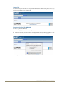
1
Operation/Reference Guide NXB-CCG NetLinx® Clear Connect™ Gateway Lighting Controls L a s t U pd a t e d : 3 /1 4 /2 0 1 2 AMX Limited Warranty and Disclaimer This Limited Warranty and Disclaimer extends only to products purchased directly from AMX or an AMX Authorized Partner which include AMX Dealers, Distributors, VIP’s or other AMX authorized entity. AMX warrants its products to be free of defects in material and workmanship under normal use for three (3) years from the date of purchase, with the following exceptions: • Electroluminescent and LCD Control Panels are warranted for three (3) years, except for the display and touch overlay components are warranted for a period of one (1) year. • Disk drive mechanisms, pan/tilt heads, power supplies, and MX Series products are warranted for a period of one (1) year. • AMX lighting products are guaranteed to switch on and off any load that is properly connected to our lighting products, as long as the AMX lighting products are under warranty. AMX also guarantees the control of dimmable loads that are properly connected to our lighting products. The dimming performance or quality there of is not guaranteed, impart due to the random combinations of dimmers, lamps and ballasts or transformers. • AMX software is warranted for a period of ninety (90) days. • Batteries and incandescent lamps are not covered under the warranty. • AMX AutoPatch Epica, Modula, Modula Series4, Modula CatPro Series and 8Y-3000 product models will be free of defects in materials and manufacture at the time of sale and will remain in good working order for a period of three (3) years following the date of the original sales invoice from AMX. The three-year warranty period will be extended to the life of the product (Limited Lifetime Warranty) if the warranty card is filled out by the dealer and/or end user and returned to AMX so that AMX receives it within thirty (30) days of the installation of equipment but no later than six (6) months from original AMX sales invoice date. The life of the product extends until five (5) years after AMX ceases manufacturing the product model. The Limited Lifetime Warranty applies to products in their original installation only. If a product is moved to a different installation, the Limited Lifetime Warranty will no longer apply, and the product warranty will instead be the three (3) year Limited Warranty. All products returned to AMX require a Return Material Authorization (RMA) number. The RMA number is obtained from the AMX RMA Department. The RMA number must be clearly marked on the outside of each box. The RMA is valid for a 30-day period. After the 30-day period the RMA will be cancelled. Any shipments received not consistent with the RMA, or after the RMA is cancelled, will be refused. AMX is not responsible for products returned without a valid RMA number. AMX is not liable for any damages caused by its products or for the failure of its products to perform. This includes any lost profits, lost savings, incidental damages, or consequential damages. AMX is not liable for any claim made by a third party or by an AMX Authorized Partner for a third party. This Limited Warranty does not apply to (a) any AMX product that has been modified, altered or repaired by an unauthorized agent or improperly transported, stored, installed, used, or maintained; (b) damage caused by acts of nature, including flood, erosion, or earthquake; (c) damage caused by a sustained low or high voltage situation or by a low or high voltage disturbance, including brownouts, sags, spikes, or power outages; or (d) damage caused by war, vandalism, theft, depletion, or obsolescence. This limitation of liability applies whether damages are sought, or a claim is made, under this warranty or as a tort claim (including negligence and strict product liability), a contract claim, or any other claim. This limitation of liability cannot be waived or amended by any person. This limitation of liability will be effective even if AMX or an authorized representative of AMX has been advised of the possibility of any such damages. This limitation of liability, however, will not apply to claims for personal injury. Some states do not allow a limitation of how long an implied warranty last. Some states do not allow the limitation or exclusion of incidental or consequential damages for consumer products. In such states, the limitation or exclusion of the Limited Warranty may not apply. This Limited Warranty gives the owner specific legal rights. The owner may also have other rights that vary from state to state. The owner is advised to consult applicable state laws for full determination of rights. EXCEPT AS EXPRESSLY SET FORTH IN THIS WARRANTY, AMX MAKES NO OTHER WARRANTIES, EXPRESSED OR IMPLIED, INCLUDING ANY IMPLIED WARRANTIES OF MERCHANTABILITY OR FITNESS FOR A PARTICULAR PURPOSE. AMX EXPRESSLY DISCLAIMS ALL WARRANTIES NOT STATED IN THIS LIMITED WARRANTY. ANY IMPLIED WARRANTIES THAT MAY BE IMPOSED BY LAW ARE LIMITED TO THE TERMS OF THIS LIMITED WARRANTY. EXCEPT AS OTHERWISE LIMITED BY APPLICABLE LAW, AMX RESERVES THE RIGHT TO MODIFY OR DISCONTINUE DESIGNS, SPECIFICATIONS, WARRANTIES, PRICES, AND POLICIES WITHOUT NOTICE. Table of Contents Table of Contents NXB-CCG NetLinx ClearConnect Gateway .........................................................1 Overview .................................................................................................................. 1 Common Applications............................................................................................... 1 Features .......................................................................................................................... 1 Product Specifications .............................................................................................. 2 FCC/ IC Information .................................................................................................. 3 Installation ..........................................................................................................5 Important Notes ....................................................................................................... 5 Codes .............................................................................................................................. 5 Cleaning .......................................................................................................................... 5 DC Adapter Power .......................................................................................................... 5 RF Device Placement....................................................................................................... 5 Installation ................................................................................................................ 6 Ethernet Pin Numbering ................................................................................................. 7 Returning an NXB-CCG to Factory Default Settings ....................................................... 7 Connecting To the NXB-CCG.................................................................................... 8 Automatic Detection ....................................................................................................... 8 ZeroConfig in Safari ........................................................................................................ 8 ZeroConfig in Other Browsers ........................................................................................ 8 ZeroConfig in NetLinx Studio.......................................................................................... 8 Troubleshooting .................................................................................................9 Web Interface Pages ........................................................................................11 Accessing the Web Interface Pages .............................................................................. 11 Configure Page ....................................................................................................... 12 Settings Tab .................................................................................................................. 12 Web Logins Tab ............................................................................................................ 14 Adding a Web Login ..................................................................................................... 14 Changing the Password of a Web Login ....................................................................... 15 Deleting a Web Login ................................................................................................... 15 Integration Logins Tab .................................................................................................. 17 Adding an Integration Login ......................................................................................... 17 Changing the Password of an Integration Login ........................................................... 18 Deleting an Integration Login ....................................................................................... 19 Add Devices Page................................................................................................... 20 Entering Activation Mode ............................................................................................. 21 Adding Devices ............................................................................................................. 21 Removing Devices ......................................................................................................... 22 Exiting Activation Mode................................................................................................ 22 NXB-CCG NetLinx® Clear Connect™ Gateway i Table of Contents Changing Device Names ............................................................................................... 23 Changing Device Integration IDs................................................................................... 23 Occupancy Group Management .................................................................................... 24 Program Page ......................................................................................................... 25 Buttons.......................................................................................................................... 26 Button Details ............................................................................................................... 27 Editing Button Defaults ................................................................................................. 27 Editing Button Names ................................................................................................... 28 Adding Virtual Buttons.................................................................................................. 28 Occupancy Sensors........................................................................................................ 29 Integration .............................................................................................................. 30 Supported Protocol....................................................................................................... 30 XML Integration File...................................................................................................... 30 Administration Page ............................................................................................... 32 Firmware Update Tab.................................................................................................... 32 Downloading a Firmware File........................................................................................ 32 Logging Tab .................................................................................................................. 34 Extracting a log from the NXB-CCG.............................................................................. 34 ii NXB-CCG NetLinx® Clear Connect™ Gateway NXB-CCG NetLinx ClearConnect Gateway NXB-CCG NetLinx ClearConnect Gateway Overview The NXB-CCG NetLinx® Clear Connect™ Gateway (FG2606) connects AMX NetLinx Controllers with Lutron's Clear Connect Dimmers, Switches, Occupancy/Vacancy Sensors and Keypads. The Gateway includes a web interface for simplified integration, configuration, and programming of Clear Connect devices. When integrated with an AMX NetLinx Controller, installers now have a simple and cost-effective path to offer smart room automation that includes light and AV control from a single interface, occupancy sensing, scheduled shutdown, and energy management. Ethernet LED RF LED Power/Status LED Antenna 1 1/8” (2.86 cm) CAT5 Cable Port Reset Button USB Cable Port 5VDC Power Jack 2.58” (6.60 cm) FIG. 1 NXB-CCG ClearConnect Wireless Gateway Common Applications The NXB-CCG is ideal for new and retrofit applications looking for the least costly way to add light and AV control to a room. The NXB-CCG is designed to interface with Lutron's Clear Connect Dimmers, Switches, Keypads, and/or Occupancy/Vacancy Sensors. Features Clear Connect Enabled – Lutron's patented RF Technology uses a quiet band that is essentially free of interference, ensuring reliable communication between system devices. Perfect Way to Add Light Control – Easily integrates with existing electrical infrastructures – simply replace the light switch. Create Light & Control Events with Room Occupancy – Use the Clear Connect Wireless Occupancy Sensor with RMS to automatically power-up and shut-down the lights and AV equipment to maximize energy conservation. Simple Web Configuration – Browse to the NetLinx Clear Connect Gateway URL to quickly add Clear Connect Enabled Switches, Dimmers, Keypads and Occupancy/Vacancy Sensors. NXB-CCG NetLinx® Clear Connect™ Gateway 1 NXB-CCG NetLinx ClearConnect Gateway Product Specifications NXB-CCG Specifications Power Requirements: • Power Consumption: 600mA @ 5VDC, DC adapter included (5V DC, 2A). • Surge Protection: To withstand surge voltages without damage or loss of operation, in accordance with IEEE C62.41-1991 Recommended Practice on Surge Voltages in Low-Voltage AC Power Circuits. • Power Failure Memory: If power is interrupted, the NXB-CCG will return to its previous state when power is restored. Front Panel Components: Power/Status LED: Displays power status and other system status indicators. RF LED: Displays the Tx / Rx activity on the RF link. Ethernet LED: Displays the connection status and Tx / Rx activity on the Ethernet link. Rear Panel Components: CAT5 Cable Port: Maximum cable length: 328 ft (100 m). USB Cable Port: Manufacturer use only. Reset Button: Press and hold for 20 seconds to restore the system to the Factory Default settings. Power Jack (to DC adapter) Operating Environment: (IEC PELV / NECR Class 2). • 32 °F to 104 °F (0 °C to 40 °C), 0% to 90% humidity, non-condensing. • Indoor use only. ESD Protection: ESD protection to withstand electrostatic discharge without damage or memory loss, in accordance with IEC 61000-4-2. Communications: • The NXB-CCG communicates to other Clear Connect devices through RF. • All devices (except wired accessory dimmers/switches) must be located within 30 feet (9 m) of the NXB-CCG. Auto Discovery: Supports the ZeroConf auto discovery protocol. Dimensions (HWD): • Without antenna: 1 1/8” x 2 5/8” x 4 7/16” (2.86 cm x 6.60 cm x 11.23 cm) • With antenna: 6 1/2” x 2 5/8” x 4 7/16” (17.15 cm x 6.60 mm x 112.27 mm) Weight: Certifications: 0.3 lbs (136.08 g) • FCC FCC Title 47 Part 15 Subpart B and C • IC • cULus UL 60950-1 Included Accessories: • 5VDC Adapter (WA-10J05FU) • CAT5 Suppression Ferrite Other AMX Equipment: • CCD-F6AN-DV-WH, Clear Connect 6A Fluorescent Dimmer (FG2606-12-WH) • CCD-RD-WH, Clear Connect 120V Accessory Dimmer (FG2606-31-WH) • CCD-RS-WH, Clear Connect 120V Accessory Switch (FG2606-32-WH) • CCD-RS-277-WH, Clear Connect 277V Accessory Switch (FG2606-33-WH) • CCD-VCRB-P-WH, Clear Connect Radio Powr SavrTM Ceiling Mount Vacancy Sensor - CA. Only (FG2606-42-WH) • CCD-6NA-WH Clear Connect Phase Adaptive Dimmer (FG2606-13-WH) • CCD-15APS-1-WH, Clear Connect Switching Plug in Device - 15 A Softswitch (FG2606-51-WH) • CCD-W6BRL-WH, Clear Connect Wall Keypad - 6 button with Raise/Lower (FG2606-61-WH) • CCD-6D-WH, Clear Connect 600W Incandescent/MLV Dimmer (FG2606-11-WH) • CCD-8S-WH, Clear Connect 120/277V Switch (FG2606-21-WH) • CCD-OCRB-P-WH, Clear Connect Radio Powr SavrTM Ceiling Mount Occupancy/Vacancy Sensor (FG2606-41-WH) 2 NXB-CCG NetLinx® Clear Connect™ Gateway NXB-CCG NetLinx ClearConnect Gateway FCC/ IC Information This device complies with part 15 of the FCC Rules and Industry Canada license-exempt RSS standard(s). Operation is subject to the following two conditions: (1) This device may not cause interference, and (2) this device must accept any interference, including interference that may cause undesired operation. Modifications not expressly approved by Lutron Electronics Co., Inc. could void the user's authority to operate this equipment. Note: This equipment has been tested and found to comply with the limits for a Class B digital device, pursuant to part 15 of the FCC Rules. These limits are designed to provide reasonable protection against harmful interference in a residential installation. This equipment generates, uses and can radiate radio frequency energy and, if not installed and used in accordance with the instructions, may cause harmful interference to radio communications. However, there is no guarantee that interference will not occur in a particular installation. If this equipment does cause harmful interference to radio or television reception, which can be determined by turning the equipment off and on, the user is encouraged to try to correct the interference by one or more of the following measures: Reorient or relocate the receiving antenna Increase the separation between the equipment and receiver Connect the equipment into an outlet on a circuit different from that to which the receiver is connected Consult the dealer or an experienced radio/TV technician for help Proper orientation of the antenna helps ensure maximum range and the best performance. The NXB-CCG should be positioned centrally to the devices being controlled, and as high and clear of obstructions as possible. The NXB-CCG utilizes an omni-directional antenna, which produces a circular pattern perpendicular to the antenna. For best performance, the antenna should be positioned vertically (tip up or down, not sideways). Try to keep the antenna at least 2 feet from metallic objects. NXB-CCG NetLinx® Clear Connect™ Gateway 3 NXB-CCG NetLinx ClearConnect Gateway 4 NXB-CCG NetLinx® Clear Connect™ Gateway Installation Installation Important Notes Codes Install in accordance with all local and national electrical codes. Cleaning To clean, wipe with a clean damp cloth. DO NOT use any chemical cleaning solutions. DC Adapter Power Using a DC adapter not rated at the proper specifications could damage the NXBCCG and possibly overheat the DC adapter. Use only the Lutron 5VDC Adapter (WA-10J05FU) included with the device. RF Device Placement All dimmers, switches, keypads and shades / draperies must be located within 30 ft (9 m) of the NXB-CCG (FIG. 2). NXB-CCG Power Source 30 feet (9 m) maximum Lutron switches/dimmers FIG. 2 RF Configuration Proper orientation of the antenna helps ensure maximum range and the best performance. The NXB-CCG should be positioned centrally to the devices being controlled, and as high and clear of obstructions as possible. The NXB-CCG utilizes an omni-directional antenna, which produces a circular pattern perpendicular to the antenna. For best performance, the antenna should be positioned vertically (tip up or down, not sideways). Try to keep the antenna at least 2 feet from metallic objects. NXB-CCG NetLinx® Clear Connect™ Gateway 5 Installation Installation 1. Find a suitable location for the NXB-CCG. 2. Mount vertically or horizontally (FIG. 3), using two #6 (M3) screws. When mounting, allow 7 in (177.8 mm) clearance for the antenna and ensure convenient access to the power plug. In order to achieve proper RF performance, do not mount unit in a metal enclosure. 3. Attach the DC adapter cord to the power jack on the NXB-CCG and insert the DC adapter plug into a receptacle (FIG. 2). #6 (M3) screws recommended Vertical Wall Horizontal Level Surface 1” 2.54 cm) FIG. 3 Installation Diagram 4. Use CAT5 Ethernet cable to connect the NXB-CCG to the chosen network’s Master. Please refer to the Ethernet Pin Numbering diagram (FIG. 5) for the correct connection. 5. Clip the included CAT5 Suppression Ferrite around the Ethernet cable (FIG. 4), 2 to 3 inches (51-76 mm) from the NXB-CCG’s Ethernet port. 1 2 3 (complete) FIG. 4 Installing the CAT5 Suppression Ferrite If the ferrite slips on the Ethernet cable, such as in a vertical installation, electrical or duct tape may be wrapped around the cable to keep the ferrite in place. 6 NXB-CCG NetLinx® Clear Connect™ Gateway Installation Ethernet Pin Numbering The numbering for pins in the Ethernet port is as follows: FIG. 5 Ethernet Pin Numbering Ethernet Pin Numbering Ethernet: Pin #: T+Ve 1 T-Ve 2 R+Ve 3 R-Ve 6 Returning an NXB-CCG to Factory Default Settings Returning an NXB-CCG to factory default settings will erase all programming from it and all system devices and will require all Clear Connect devices to be reprogrammed into the system 1. Press and hold the Reset button (FIG. 1) on the device for 20 seconds. 2. The Power/Status LED will start flashing slowly for approximately10 seconds, after which it will start rapidly flashing for approximately 20 seconds and then remain on. 3. The device has been returned to its factory default settings. Returning the NXB-CCG to its factory default settings does not do the same for any connected Lutron Clear Connect devices. They may have to be returned to factory defaults separately before being reattached to the NXB-CCG’s network. NXB-CCG NetLinx® Clear Connect™ Gateway 7 Installation Connecting To the NXB-CCG Automatic Detection The NXB-CCG supports mDNS or ZeroConfig. This allows the device to be automatically detected on a network with a ZeroConfig-capable browser or Apple’s Bonjour plug-in. The Safari web browser has a Bonjour browser built into it in the Bookmarks window. The Bonjour plug-in is not available in the mobile version of Safari. ZeroConfig in Safari To use the Safari browser: 1. Click the Bookmarks icon in the top left corner. 2. Click “Bonjour” in the collections list. 3. Select the icon that corresponds to the host name of the NXB-CCG or select it from the bookmark list (FIG. 6). FIG. 6 Bonjour browser layout ZeroConfig in Other Browsers Some standalone ZeroConfig browsers exist that vary in their feature set. Most of them will allow you to discover the devices on the network and find the IP addresses. The NXB-CCG will, by default, have the host name “NXB-CCG-“, followed by the serial number of the device. Other browsers have plug-ins that can be downloaded and installed for use in autodetecting the NXB-CCG via the ZeroConfig protocol. ZeroConfig in NetLinx Studio Netlinx Studio has a built in ZeroConfig browser to find the NXB-CCG and display its web page interface. NetLinx Studio is available at www.amx.com. 8 NXB-CCG NetLinx® Clear Connect™ Gateway Troubleshooting Troubleshooting If you should have issues with installing an NXB-CCG or with setting up a network, consider the following options: Ensure power is connected to the NXB-CCG Ensure a network connection is made between the NXB-CCG and a router/PC Factory default the NXB-CCG Place a router between the NXB-CCG and the controlling PC Refresh the NXB-CCG web page Cycle power to the NXB-CCG Ensure power is connected to all devices being programmed in the system Ensure recommended device spacing, with a maximum of 30 feet (9.14 meters) between devices, and a minimum of 10 feet (3.05 meters) between NXB-CCGs. NXB-CCG NetLinx® Clear Connect™ Gateway 9 Troubleshooting 10 NXB-CCG NetLinx® Clear Connect™ Gateway Web Interface Pages Web Interface Pages Accessing the Web Interface Pages The NXB-CCG uses Web-based interface pages that can be accessed through most Web browsers. Enter the device’s IP address (obtainable either through a ZeroConf-enabled browser or through NetLinx Studio) to access the Login page (FIG. 7). FIG. 7 Login page Login Page Username: Enter the username (default: admin). Password: Enter the password for the device (default: 1988). Licenses and Software Notices: Click this link to view the current software license and notices concerning the software version. To access the Web Interface pages: 1. From any computer or Netbook that has access to the LAN on which the NXB-CCG resides, open a web browser and type the IP address of the target NXB-CCG unit in the Address Bar. 2. In the Login page, enter your username and password. (The default username and password are admin and 1988.) For reference, the top right corner of the screen displays the version of the software currently running on the NXB-CCG. The Web Interface Pages are available via http or https. The http page will be enabled by default and will be the default page upon first logging in. If desired, you can change the URL to https to access the secure web page. You can also disable the http page completely in the Settings page (page 12) NXB-CCG NetLinx® Clear Connect™ Gateway 11 Web Interface Pages Configure Page Once logged in, the Web interface defaults to the Settings tab of the Configure page. From here, the administrator may access other tabs and pages to add or change Web and integration logins and passwords, change network or security settings, add devices to a network, or control the programming of buttons on an individual device. Settings Tab The NXB-CCG’s network settings can be modified via the Settings tab of the Configure page (FIG. 8). FIG. 8 Configure - Settings tab Settings Tab Network Settings: DHCP: Allows enabling or disabling of DHCP functionality.When Disabled, the other Network Settings entries are editable. CCT IP Address: Displays the IP address of the device. Subnet Mask: Displays the device’s subnet mask. Gateway: Displays the device’s gateway address. DNS Server 1: Displays the device’s main DNS server address. DNS Server 2: Displays the devices optional secondary DNS server address. Host Name: Displays the device’s host name on the network. Zero Configuration: Allows enabling or disabling of ZeroConfig functionality. Security Settings: 12 Telnet: Enables or disables Telnet functionality. Telnet Port: Displays the device’s Telnet port. NXB-CCG NetLinx® Clear Connect™ Gateway Web Interface Pages Settings Tab (Cont.) HTTPS Only: Enables or disables the ability of the device to be accessed solely through a secure page. Update: Click this button to save and update all changes. From the Settings tab, DHCP functionality may be enabled or disabled. When DHCP is disabled, the IP address, subnet mask, gateway, and two DNS servers can be set manually. The DNS name may also be set at this time. In the Network Settings section, ZeroConfig autodetection may also be disabled, but this is not recommended. For security purposes, the raw integration port can be disabled or changed via the Telnet enable/disable buttons and the Telnet port field. Using the HTTPS Only buttons, the non-encrypted HTTP page may be enabled or disabled. If this is enabled, this forces users to connect to the device through the encrypted HTTPS page only. NXB-CCG NetLinx® Clear Connect™ Gateway 13 Web Interface Pages Web Logins Tab The Web Logins tab of the Configure page controls management of web logins (FIG. 9). FIG. 9 Configure - Web Logins tab Web Logins Tab Username: Displays the usernames for each of the current web logins. Change Password: Click this link to change the password for the web login. Delete User: Click this link to delete the user. This feature is disabled if only one user is listed. Add Web Login: Click this button to add a new web login to the current list. The Web Logins tab will allow up to five separate web login entries. You must enter at least one for the administrator. Adding a Web Login To add a web login: 1. Click the Add Web Login button to open the Add Web User window (FIG. 10). FIG. 10 Add Web User window 2. Enter the new web login username and password in the appropriate fields. You may not duplicate a user name that already exists. 14 NXB-CCG NetLinx® Clear Connect™ Gateway Web Interface Pages The Web Login Password allows most special characters. Do not use periods, quotation marks, apostrophes, or the plus sign. 3. Click Create or press Enter on your keyboard to create and save the login. 4. The new web login will now appear in the Web Logins tab. Changing the Password of a Web Login To change a web login’s password: 1. In the Web Logins tab, click the Change Password link on the appropriate web login to open the Change Password window (FIG. 11). FIG. 11 Change Password window 2. Enter and confirm the new password. 3. Click Change or press Enter on your keyboard to confirm the new password. Deleting a Web Login To delete a login: 1. In the Web Logins tab, click the Delete User link on the appropriate web login to open the Delete User window (FIG. 12). FIG. 12 Delete User prompt 2. Confirm that you wish to delete that web login by clicking Yes. NXB-CCG NetLinx® Clear Connect™ Gateway 15 Web Interface Pages 3. If only one web login is visible in the Web Logins tab, this login may not be deleted, and the Delete User link is disabled. 16 NXB-CCG NetLinx® Clear Connect™ Gateway Web Interface Pages Integration Logins Tab The Integration Logins tab on the Configure page allows management of integration logins (FIG. 13). FIG. 13 Configure - Integration Logins tab Integration Logins Tab Username: Displays the usernames for each of the current integration logins. Change Password: Click this link to change the password for the integration login. Delete User: Click this link to delete the user. Add Integration Login: Click this button to add a new integration login to the current list You may have up to 10 integration logins at one time, with a minimum number of zero. The logins that are created in this tab can be used via SSH or raw socket integration. Adding an Integration Login To add a new user login: 1. From the Configure page, select the Integration Logins tab. 2. Click the New Integration Login button to open the Add Integration User window (FIG. 14). FIG. 14 Add Integration User window NXB-CCG NetLinx® Clear Connect™ Gateway 17 Web Interface Pages 3. Enter the new username and password and click Create. If the username or password use incompatible characters, this opens a prompt window for the username (FIG. 15) or the password (FIG. 16). FIG. 15 Username prompt FIG. 16 Password prompt The Integration Login Password allows most special characters. Do not use periods, quotation marks, apostrophes, or the plus sign. 4. The new username will appear in the Integration Logins tab. Changing the Password of an Integration Login To change a user’s password: 1. From the Configure page, select the Integration Logins tab. 2. In the appropriate user entry, select Change Password to open the Change Password window (FIG. 17). FIG. 17 Change Password window 3. Enter and confirm the new password and click Change. 4. The new password is now enabled. 18 NXB-CCG NetLinx® Clear Connect™ Gateway Web Interface Pages Deleting an Integration Login To remove a login: 1. From the Configure page, select the Integration Logins tab. 2. In the appropriate user entry, select Delete User to open the Delete User window (FIG. 12). FIG. 18 Delete User window 3. Confirm that you wish to remove this user by clicking Yes. 4. The login will no longer appear in the Integration Login tab. NXB-CCG NetLinx® Clear Connect™ Gateway 19 Web Interface Pages Add Devices Page The Add Devices page (FIG. 19) allows you to add, remove, and manage up to 10 devices within the NXBCCG network. FIG. 19 Add Devices page Add Devices Page Add/Remove Devices: Click this button to add new devices to the NXB-CCG network. Name: Displays the name of the device in the network. Type: Displays the type of device in the network. ID: Displays the device ID number (1-10) in the network. Action: This link allows removal of the device from the network. Show Occupancy Groups: Click this box to show all occupancy groups within the devices in the network. Manage: Click this link to manage occupancy groups. All the added devices must be set to their factory defaults before they can be added to the system. 20 NXB-CCG NetLinx® Clear Connect™ Gateway Web Interface Pages Entering Activation Mode To enter Activation Mode: 1. In the Add Devices page, click the Add/Remove Devices button to enter the Add/Remove Devices Mode (FIG. 20). FIG. 20 Entering Add/Remove Devices Mode 2. Wait while the NXB-CCG attempts to enter activation. a. Entering activation may fail due to another system being in activation. This will open the Unable to enter add/remove device mode popup window (FIG. 21). FIG. 21 “Unable to enter/remove device mode” prompt You may retry entering the Add/Remove Device mode when the other system is out of that mode. b. Entering activation may fail due to house code collision. This condition is extremely unlikely, as random house codes are picked when the device first enters activation and upon collisions with other house codes. 3. The network is now waiting for devices to report themselves. The devices that you wish to activate should have all their LEDs blinking slowly (two seconds on, one seconds off). If the devices are not blinking, triple-tap-hold-triple tap them to restore them to their factory defaults, and then wait a minute until they begin showing the activation mode feedback. Adding Devices Once in Activation Mode, new devices can be added to the system and currently activated devices can be removed. To add new devices, do the following: 1. Press and hold the device to be added to the network, and verify that is exhibiting the appropriate LED feedback on the appropriate button. Sensors will not show activation feedback. NXB-CCG NetLinx® Clear Connect™ Gateway 21 Web Interface Pages 2. The device will then report itself to the system. 3. In the Add Devices page, the Device Heard popup window appears (FIG. 22), displaying the type of device that reported itself. FIG. 22 Device Heard window 4. If the device is not a valid device for the network, the Add Devices page displays a message stating this, and the device cannot be activated. 5. In the Device Heard window, enter a unique name for the device and add it to the system by clicking Add or pressing Enter on your keyboard. Removing Devices To remove a device: 1. In the Add Devices page, click the Remove link in the Action column while the device is in Activation Mode. 2. When prompted, click Yes. Exiting Activation Mode To exit Activation Mode: 1. With the Add Devices page in Activation Mode, click the “Done” button. The NXB-CCG will start exiting all devices from activation. FIG. 23 Exiting Add/Remove Devices Mode 2. After about 10 to 15 seconds, the original Add Devices screen appears, indicating that activation was exited successfully. 22 NXB-CCG NetLinx® Clear Connect™ Gateway Web Interface Pages Changing Device Names Devices that are added to the NXB-CCG network are named during the activation process, but their names can be modified afterward, either in or out of Activation Mode. To change a device’s name: 1. In the Add Devices page, click on the device’s name to open the Device Name window (FIG. 24). FIG. 24 Device Name window 2. Enter the new device name in the Device Name window field. 3. Click Save or press Enter on your keyboard to save your changes. Changing Device Integration IDs Devices that are added to the NXB-CCG network can have their IDs changed, whether in or out of Activation Mode. This is the integration ID that is used to refer to the device when controlling the system via the integration protocol. To change the Device Integration ID: 1. Click on the ID of the device to be modified to open the Device Integration ID window (FIG. 25). FIG. 25 Device Integration ID window 2. Enter the new ID number, from 1 to 10. 3. When finished, click Save or press Enter on your keyboard to save your changes. NXB-CCG NetLinx® Clear Connect™ Gateway 23 Web Interface Pages Occupancy Group Management Occupancy grouping allows coverage of a larger space than one sensor can cover. For example, if you want a conference room to shut off lights when no one is in it after a specified timeout, and it is too large for one occupancy sensor to see the entire room, you can add multiple sensors to the system and assign them all to the same group. Once in a group, the unoccupied state will not be triggered until all of the sensors have reported this state. This will prevent the lights shutting off while people are still in the room but out of view of the sensor, or integration reporting this condition for the same situation. When Occupancy sensors are added to your network, additional capabilities are available on the Add Devices page for managing occupancy sensor grouping. When occupancy sensors are activated to the system, the Show Occupancy Groups box is available. If the box is unchecked, the occupancy group ID and name for each sensor is hidden in the Devices list. However, if it is checked, this group is displayed (FIG. 26). FIG. 26 Occupancy Group ID & Name Clicking on the Manage link in the lower left corner of the screen opens a window allowing you to add and remove occupancy groups from the system (FIG. 27). You can use these groups to change the grouping of the sensors that are networked to the NXB-CCG. FIG. 27 Manage Occupancy Groups window 24 NXB-CCG NetLinx® Clear Connect™ Gateway Web Interface Pages Program Page The Program page can be used to program Clear Connect devices to respond to scene activations, occupancy events, and physical keypad button presses (FIG. 28). All programming is done in real time on the system. FIG. 28 Program tab If the device that you are trying to assign to a button or sensor or the device that you are programming (keypad or sensor) is not physically present or is not powered, programming will likely fail. NXB-CCG NetLinx® Clear Connect™ Gateway 25 Web Interface Pages Buttons Buttons programmed with the NXB-CCG will all have “single action” programming, with the exception of raise/lower buttons on keypads. This means that presses of these buttons will always send the programmed devices to their programmed level regardless of the state of the devices. This is true for both physical keypad buttons and virtual integration buttons. The LEDs on virtual and physical buttons are “scene logic,” meaning that they are lit when all devices programmed to the associated button are on at the exact levels that are programmed. The Program page allows you to program devices to buttons. Clicking a button in the left tree of the Program page view will show a window on the right with details on that button (FIG. 29). FIG. 29 Device Details When a button already contains programming, this programming is displayed in the button details window. Clicking the Test Programming button will test the current programming by sending the devices to those levels. Devices can be removed from the button by clicking the Remove link on the row corresponding to the device to be removed. 26 NXB-CCG NetLinx® Clear Connect™ Gateway Web Interface Pages Button Details To add devices to the button 1. Click the Add Device button in the Button Details pane (FIG. 29) to open the Add Devices to Button window (FIG. 30). FIG. 30 Add Devices to Button window 2. Select the devices to add by clicking the appropriate check boxes. 3. Click Add to save your changes. Editing Button Defaults By default, added dimmers will have a programmed level of 100%, fade of 2 seconds, and no delay. Switches will have a programmed level of On with no delay. The delay cannot be modified. These defaults can be changed on the Button Details pane by clicking on the Level column (FIG. 31) or the Fade column (FIG. 32). FIG. 31 Dimmer Programming - Level FIG. 32 Dimmer Programming - Fade NXB-CCG NetLinx® Clear Connect™ Gateway 27 Web Interface Pages Editing Button Names The name of buttons can be changed from their defaults by right clicking on the button in the Devices tree view on the left of the screen (FIG. 33). FIG. 33 Edit Button Name Adding Virtual Buttons The NXB-CCG has 100 virtual buttons that can be programmed for integration purposes. When the NXB-CCG Processor entry is expanded in the Devices tree view only 10 buttons are shown by default. If you need to program more than 10 virtual buttons, you can show more of the 100 by right clicking the NXB-CCG Processor text in the Devices tree view (FIG. 34). Clicking this prompt will show additional virtual buttons 11 through 20, and so on. FIG. 34 Add New Virtual Buttons 28 NXB-CCG NetLinx® Clear Connect™ Gateway Web Interface Pages Occupancy Sensors Occupancy sensors show up in the Program page in the same way as a keypad or dimmer. The occupied and unoccupied actions can be programmed individually to loads. This allows you the ability to create a vacancy sensor by not assigning any programming to the occupied action. Occupancy sensors can be programmed in groups (where occupancy is determined by the state of all sensors in the group) or individually (FIG. 35). FIG. 35 Occupied Action Details NXB-CCG NetLinx® Clear Connect™ Gateway 29 Web Interface Pages Integration The NXB-CCG supports a subset of the Lutron Integration Protocol (available on the Lutron website) that is relevant for the devices that are supported by the NXB-CCG. The NXB-CCG also provides the ability to download an XML file that provides integration information about the system that is currently programmed to it (in the Lutron XML format). Supported Protocol Supported Integration Commands 1) ‘#OUTPUT,<integration ID>,1,<level>’ (goto level) 2) ‘#OUTPUT,<integration ID>,1,<level>,<fade time>’ (goto level with fade) 3) ‘#OUTPUT,<integration ID>,2’ (raise) 4) ‘#OUTPUT,<integration ID>,3’ (lower) 5) ‘#OUTPUT,<integration ID>,4’ (stop) 6) ‘?OUTPUT,<integration ID>,1’ (query level) 7) ‘#DEVICE,<integration ID>,<component number>,3’ (button press) 8) ‘#DEVICE,<integration ID>,<component number>,4’ (button release) 9) ‘#DEVICE,<integration ID>,<component number>,9,1’ (set led on) NOTE: you cannot set the state of programmed keypad LEDs. 10) ‘#DEVICE,<integration ID>,<component number>,9,0’ (set led off) NOTE: you cannot set the state of programmed keypad LEDs. 11) ?DEVICE,<integration ID>,<component number>,9 (query led state) 12) ?GROUP,<integration ID>,3 (query occupancy group state) Supported Monitoring Responses 1) ‘~OUTPUT,<integration ID>,1,<level>’ (dimmer level reporting) 2) ‘~DEVICE,<integration ID>,2,3’ (occ sensor occupied, component always 2) 3) ‘~DEVICE,<integration ID>,2,4’ (occ sensor unoccupied, component always 2) 4) ‘~GROUP,<integration ID>,3,3’ (occ group occupied, component always 3) 5) ‘~GROUP,<integration ID>,3,4’ (occ group unoccupied, component always 3) 6) ‘~DEVICE,<integration ID>,<component number>,3’ (button pressed) 7) ‘~DEVICE,<integration ID>,<component number>,4’ (button released) 8) ‘~DEVICE,<integration ID>,<component number>,9,<state>’ (led state 1/0) XML Integration File The XML file can be downloaded from the web port of the NXB-CCG (80) and asking for the “xml” page (FIG. 36). If this is done via a browser, you must either already be logged into the NXB-CCG login page or you will be prompted to login. The credentials can also be added to the web address to automate this process (“IP-Address-Of-CCT/xml?login=<username>&password=<password>”). 30 NXB-CCG NetLinx® Clear Connect™ Gateway Web Interface Pages FIG. 36 XML Integration File NXB-CCG NetLinx® Clear Connect™ Gateway 31 Web Interface Pages Administration Page The Administration page allows control of firmware updates and device logs. Firmware Update Tab Firmware updates may be made through the Firmware Update tab (FIG. 37). This section allows you to select a .lef firmware update file and upload it to the NXB-CCG. FIG. 37 Administration - Firmware Update tab Administration - Firmware Update Page Choose File: Click this button to select the firmware file to be downloaded. Update Firmware: Click this button when the firmware file has been selected. Downloading a Firmware File To download a firmware file: 1. Click on the Choose File button to open the Firmware Path field. If you do not know the exact path, click the Browse... button to search for the .lef file. The file to be downloaded must be a valid .lef file provided by Lutron or the update will not succeed 2. Once a file has been chosen to upload, the Update Firmware button is now enabled. Clicking on this button will start the Update Firmware process (FIG. 38). FIG. 38 Retrieving Information prompt DO NOT remove power from the NXB-CCG during the Update Firmware process. 3. Upon completion of the firmware update process, a pop-up dialog will be displayed with the status of the update (FIG. 39). Upon success, you may have to refresh and/or login to the web page again. FIG. 39 Firmware Update Successful 32 NXB-CCG NetLinx® Clear Connect™ Gateway Web Interface Pages Downgrading the firmware to a previous version will delete the current programming on the NXB-CCG. Some firmware update failures may cause the NXB-CCG to reboot. If this occurs, wait till the startup feedback is complete and then login to the Web Interface pages to try to update again. Ensure that you are uploading a valid firmware update file provided by Lutron. NXB-CCG NetLinx® Clear Connect™ Gateway 33 Web Interface Pages Logging Tab The NXB-CCG supports extracting device logs from the NXB-CCG for troubleshooting purposes. These may be extracted through the Logging tab (FIG. 40). FIG. 40 Administration - Logging tab Extracting a log from the NXB-CCG To extract a log from the NXB-CCG: 1. From the Logging tab, click the Extract Logs button. 2. A Lutron log file will be downloaded into the default Downloads directory of the browser (FIG. 41). This file can then be used by Lutron to view the device logs for troubleshooting and debugging. FIG. 41 Log file download 34 NXB-CCG NetLinx® Clear Connect™ Gateway Web Interface Pages NXB-CCG NetLinx® Clear Connect™ Gateway 35 In the ever-changing AV industry, continual education is key to success. AMX University is dedicated to ensuring that you have the opportunity to gather the information and experience you need to deliver strong AMX solutions. Plus, AMX courses also help you earn CEDIA, NSCA, InfoComm, and AMX continuing education units (CEUs). Visit AMX University online for 24/7/365 access to: - Schedules and registration for any AMX University course - Travel and hotel information - Your individual certification requirements and progress 3000 RESEARCH DRIVE, RICHARDSON, TX 75082 USA • 800.222.0193 • 469.624.8000 • 469-624-7153 fax • 800.932.6993 technical support • www.amx.com 3/12 ©2012 AMX. All rights reserved. AMX and the AMX logo are registered trademarks of AMX. AMX reserves the right to alter specifications without notice at any time. Increase Your Revenue through education + knowledge