1
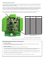
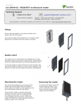
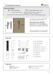
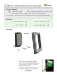
02/11/2011
Paxton
Ins-30027 Hands free interface
Technical Support
01273 811011
[email protected]
Technical help is available:
Monday - Friday from 07:00 - 19:00 (GMT)
Saturday from 09:00 - 13:00 (GMT)
Documentation on all Paxton products can be found on our website - http://www.paxton.co.uk/
What is hands free?
The hands free system increases the effective read range of a standard Paxton P or KP series reader. Standard
tokens use the readers radio field to power the token but hands free tokens have a battery and so only require a
much weaker signal to be activated.
The system comprises of a compatible reader (see read range table), a hands free interface and hands free tokens
(keycard or keyfob). The system operates by using the reader to wake up the battery powered token which then
communicates with the interface and its long range receiver aerial.
Existing P and KP readers can be used without modification. The hands free interface takes its power from the
control unit and therefore does not require a power supply.
Hands free tokens also include a standard PROXIMITY ID chip and can therefore be presented to any compatible
proximity reader whether they are using the hands free interface or not.
Hands free keyfob
Net2 control unit
P series reader
Switch2 control unit
Hands free interface
Hands free keycard
Before you install
Positioning readers
Hands free readers should be positioned so that their transmission fields do not overlap.
(see table on back page for typical hands free ranges)
For example, the minimum distance between a P200 and a P50 reader should
be 3.6 m (P200 hands free range = 2.5 m + P50 hands free range = 1.1 m)
For optimum keyfob battery life please choose your reader location carefully to
avoid placing it within hands free range of work stations, rest or smoking areas.
Read in, read out
When using in and out readers, users may be picked up by both readers as they move through the door which
will reduce the reliability of any roll call or anti-passback application. Ensure that sufficient spacing is provided
between these readers for optimum range and reliability.
Positioning the interface
The interface should be positioned as close as practical to the reader. A distance from interface to reader of
10 to 15 meters can be achieved but wireless technology is susceptible to environmental factors and so if
problems are experienced it may be necessary to move the interface closer to the reader.
The hands free interface should not be housed in a metal enclosure as it contains the main receiver aerial.
Sticky feet allow the interface to be stuck to the ACU wiring label in a PSU plastic housing.
Wiring
Entry confirm button
(optional)
Exit/Entry
0V
0V
Green LED
12V dc
12V dc
12V dc
Entry Confirm (opt)
Red LED
Red LED
Amber LED
Green LED
Green LED
Reader
Data/D0
Clock/D1
Control Unit
Amber LED
Data/D0
Clock/D1
Media Detect
Media Detect
0V
Not connected
0V
Entry
Entry
Access
Power
Connection to a control unit
reader port
Hands Free Interface
Installation
No additional power supply is required for this installation. Power is supplied by the ACU reader port.
Complete the wiring between the P series reader, the hands free module and the ACU before powering up
the ACU. This will ensure that the reader firmware is reconfigured for hands free operation.
Cable extensions
Readers can be extended using Belden CR9540 10-core overall screened cable to a maximum of 100 metres.
Firmware download
Hands free firmware for the P series reader will be downloaded from the interface to the reader as soon as it is
powered up. This is indicated by flashing amber and red LED's on the reader. Once complete all LED's will be lit.
This may take up to 10 minutes to complete. Do NOT disconnect power during the firmware update.
If the firmware update is still taking place after 10 minutes then remove and then re-connect the ACU cable.
Listen to the reader, the reader should NOT beep. If the reader beeps within approximately 10 seconds of
power up it will not take the firmware update. Repeat the process until the reader does NOT 'beep' on power
up. Then leave for 10 mins to allow the update to take place.
Using an entry confirm button
Where more than one door interface can pick up the hands free token, a 'push to make' button can be used
to select the required door. Where fitted, the LED on a confirm button will flash for 5 seconds after the hands
free token has been recognised and must be pressed to unlock the door.
Once an entry confirm button has been fitted to the interface PCB, perform the following sequence:
1. Power down the interface board.
2. Power up the interface board.
3. Press and hold the entry confirm button for a minumum of 3 seconds within 60 seconds of power up.
To disable the use of the button, repeat the above sequence.
Changing frequency channel
If you are experiencing problems with the range or reliability this may be due to poor reader positioning, adjacent
interfering 125 kHz or 2.4 GHz equipment, e.g. an adjacent wireless PC network. Please refer to the 'Before you
install' information regarding unit locations.
If you are still unable to improve the system performance then you may try an alternative 2.4 GHz channel using
Switch 1. The system has 16 channels available. (Unless keycard SW2 is selected) The frequency switch is set
to 4 (channel 15) but this can be changed using a small flat blade screwdriver. Take care not to contact the circuit
board with the screwdriver blade as this may damage components. Power cycle the unit after any changes.
SW2 - Keycard button 1 and 2 fixed channels - If either switch 1 (Channel 26) or switch 2 (Channel 11) is set,
the rotary frequency switch is disabled. If both switches are selected, the interface will not operate.
Interface PCB
Switch
position
GHz
IEEE 802.15.4
channel
0
2.405
11
1
2.41
12
2
2.415
13
3
2.42
14
4
2.425
15
5
2.43
16
6
2.435
17
7
2.44
18
8
2.445
19
9
2.45
20
A
2.455
21
B
2.46
22
C
2.465
23
D
2.47
24
E
2.475
25
F
2.48
26
SW1. Rotate the switch to select an
alternate channel.
The switch will initially be set to default position '4'
The hands free tokens will automatically configure themselves to use the new channel.
Enrolling hand free keyfobs and keycards
Hands free keyfobs
These tokens should be assigned to users as per standard keyfobs. They will then operate with standard
Paxton readers or via a hand free setup when in range.
Hands free keycards
Keycards should first be assigned to users as per the hands free keyfob.
To enable the buttons, the keycard must first be presented to the P series reader and then used in hands free
mode. The keycard stores the details of this interface and can then activate the door using a button.
A keycard can be used in normal hands free mode and also in local passive mode with other Paxton readers.
Switch SW2 is used to select the fixed channels used by the two keycard buttons. Select either switch 1 or 2
to set which keycard button the interface will respond to.
The unit must be power cycled if the switch position is changed to activate the new setting.
Technical Help
Here is the list of topics about this product that receive the most technical support enquiries.
We list them here to help you speed up the installation and trouble shooting process.
1 - Hands Free - The read range is very poor - Where is the best position for the hands free interface?
QMount the interface within 15 m of the reader. The wireless signal will not travel through metal or water and will be influenced
Qby building features and other 2.4 GHz wireless sources, including WiFi networks and DECT phones. The ideal location is to
Qprovide a 'line of sight' to approaching card users. Avoid putting the interface where metal objects, (e.g. wire fences, vehicles,
Qetc.) can block the signal. If it is to be used outside, it should be contained with a plastic weatherproof box. Do not use metal.
Q
QWhen attaching to a post, the interface should not be fixed behind the metal backplate used to mount the reader. If used from
Qa vehicle, a high position is desirable to provide a path through the vehicle glass from keycard/fob to the hands free interface.
2 - Keycards - Can I improve the read range on curved driveways?
QIt is possible to parallel two or more hands free interface units onto the same ACU reader port, increasing the coverage area.
QThe keycard will choose one to communicate with each time it is used.
QSee also: AN1091 - How to achieve the best read range with hands free equipment < http://paxton.info/867 >
3 - How do I set up the Keycard Buttons?
QThe keycard must first be read in hands free mode by the interface without pressing any buttons. Ensure that no other hands
Qfree devices are in the range of the reader. If the card does not enrol, come out of the reader range for at least 2 seconds.
QThe keycard has two buttons - each can store multiple interface addresses in its memory.
4 - Hands Free - Keycard button problems
QCorrect practice for using the keycards:
Q- Press button firmly once - Do not press the button again within 2 seconds - Avoid multiple button
Q presses in succession as this may overrun the output buffer of the interface locking it for 10 seconds.
Q- Point the Keycard in the direction of the interface - Avoid pressing a button when not in line of sight with the interface.
QEnsure switch SW2 on the Hands Free Interface is set to the correct position for the button being used (1 or 2).
5 - Net2Air - What does this mean?
QNet2Air is a term used to describe the wireless communication protocol used by Paxton products in much the same way
Qas Bluetooth. The Net2Air protocol is not open, only Paxton products can use this technology.
6 - If you power cycle the reader, the hands free token does not always read.
QHands free tokens have features to extend battery life. These include a block on repeated reads at the same door whilst the
Qkeyfob remains in range. If the token is read at power up, it must be moved out of range before it will be read again.
Specifications
Dimensions
Electrical
Voltage
Width
Height
Depth
120 mm
120 mm
40 mm
Min
Max
11V DC
14V DC
2.405 GHz
2.480 GHz
80 mA
Current
Carrier frequency
600 µs
Clock and data bit period
Additional power supply required
System Specification
No
Min
Max
1
Readers per interface
Yes
Button confirmation input
Belden 9540
Cable type for extensions
100 m
Cable length between ACU and reader
15 m
Distance between interface and reader
Read range with hands free token
Min
Max
P38
850 mm
P50
1100 mm
P75
1500 mm
P200
2500 mm
2000 mm
P200E metal mount
Environment
Operating temperatures - all items
Waterproof
Min
Max
-20 °C
55 °C
NO - If used externally, it must be protected in a plastic weatherproof housing
The declaration of conformity is available on request. Contact details are provided at:
http://paxton.info/596