1
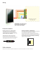
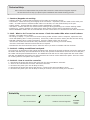
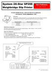
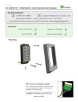
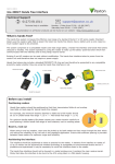
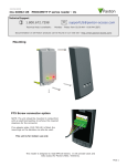
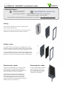
10/11/2010
Ins-30040-US
PROXIMITY architectural reader
Paxton
Technical Support
1.800.672.PAXT
Technical help is available:
[email protected]
Monday - Friday from 02:00 AM - 8:00 PM (EST)
Saturday from 04:00 AM - 08:00 AM (EST)
Documentation on all Paxton products can be found on our web site - http://www.paxton-access.com/
Fitting
Ensure that the backbox is mounted vertically and is
square with the wall surface.
Care must be taken when doing this, as no further 'twist'
adjustment is possible within the reader mountings.
Reader insert
The reader insert is held against the backplate by an outer
decorative bezel secured with 4 small screws. Remove these
screws to release the bezel and refit after adding the insert.
If you have made an insert of less than 3/16 inch thick, this
can still be fitted by using the 3 nylon screws supplied in the
fitting kit to hold the insert against the bezel. (see diagram)
Mounting the reader
Removing the reader
Line up the two locating pins on the top of the
reader with the top plate inside the backbox.
Once located, the reader can be clipped into the
box at the bottom using the clip feature.
To remove the reader, insert the
tool provided into the cut out
on the underside of the reader.
Push up the clip and pull the
reader from the backbox.
Check that the reader is located against the
surface of the wall. If there is a gap between
the reader and the wall, or if the reader will
not successfully clip into the box, remove the
reader and adjust the mounting plates inside the
backbox using a 3 mm Allen key.
Wiring
Connection to a control
unit reader port
IMPORTANT: This reader cannot
be connected in parallel with
other readers and keypads.
Connection modules
Reader junction box (325-020-US)
This module can be used to provide a
connection point for the reader RJ45 plug.
The terminals on the module are then wired
color for color to the controller.
Alternatively, the reader can be wired
directly into the screw terminals of the
control unit by first cutting off the RJ45 plug
and stripping back the wires in the cable.
Reader Port Module (325-030-US)
This module may be purchased separately to speed up
the installing and replacement of readers.
The reader port module is designed to convert the
standard reader ports on Switch2 and Net2 controllers
to accept one or two RJ45 connections. Pull off the
screw terminal block from the reader port and simply
replace it with this module.
Cable extensions
Readers can be extended using Belden CR9538 8 core overall screened cable to a maximum of 500 feet.
Technical Help
Here is the list of topics about this product that receive the most technical support inquiries.
We list them here to help you speed up the installation and trouble shooting process.
1 - Readers/Keypads not working.
Q- Software settings - Confirm that the settings of the reader or keypad are correct.
Q- Connections - Check the wiring and integrity of the connectors. If possible, test this reader on the other port.
Q- Cable - To confirm that an extended reader cable is not at fault, wire the reader directly to the port.
Q- Supply voltage - Confirm that the voltage is within specification. (see table)
Q- User token - Confirm that the user token used for testing is OK by presenting it to a known working reader.
Q- Interference - Confirm whether the reader works when tested 'in hand' and not mounted on the wall.
Q Ensure PROXIMITY readers are not mounted back to back or that there is no interference from other RF devices.
2 - Net2. What to do if a user has no access - Check the reader LEDs when a card is shown.
QQQQQ
Q
Q-
No LEDs - the reader has no power.
No change in display - try the card on a known working reader. If there is still no response, replace the card.
Green LED flashing when a card is presented; check relay 1 LED to check for activity and also the lock wiring.
Red LED is flashing when a card is presented; check the validity of the user at the PC.
Check user's access level and ensure they should have access by clicking on Current Validity.
Check the 'Valid Until' date and confirm this has not expired.
Reinstate the ACU from the doors screen. Select the ACU's you wish to reinstate and then click OK.
3 - Switch2 - Adding an additional card pack.
QYou need to be in possession of the original enrolment card. Present the original enrolment card to the reader and
Qthe Amber LED will flash, Green & Red LEDs will be off, then present the Enrolment card from the new card pack;
Qthe reader will beep and all LEDS will be lit. The additional cards will now be valid. Repeat this with each reader
Qand with any additional card packs. Any valid enrolment card can be used to add further packs. This is the same
Qfor enrolling function card packs onto a system.
4 - Switch2 - How to reset the controller.
Q1.
Q2.
Q3.
Q4.
Q5.
Disconnect the power and remove the wires from the Green and Mauve terminals
Insert a wire link between the Green and Mauve terminals
Reconnect the power (the unit will bleep 4 times)
Disconnect the power and remove the link wire, reconnect the Green and Mauve wires
Reconnect the power (the unit will bleep 3 times per second). The unit is ready to be enrolled.
Suitability
Security sensitive doors
Accepts customised inserts and bezels
Wet environments
Readers mounted together
12 inches
between
readers
Specifications
Environment
Operating temperatures - all items
Min
Max
-20 °C (-4 °F)
+55 °C (+131 °F)
IPX7
Waterproof
Cable length
Electrical
Voltage
5 yards
Min
10V DC
Max
14V DC
140 mA
Current
Carrier frequency
125 kHz
600 µs
Clock and data bit period
Dimensions
Width
Height
4
3/8”
Depth
Reader
2
Backbox
2 3/8”
4”
1”
Token
Keyfob
Hands Free Token
1 1/2”
1”
15”
Read Range
3/4”
3/8”
FCC Compliance
This device complies with Part 15 of the FCC Rules. Operation is subject to the following two conditions:
(1) this device may not cause harmful interference, and (2) this device must accept any interference
received, including interference that may cause undesired operation. Changes or modifications not expressly
approved by the party responsible for compliance could void the user's authority to operate the equipment.