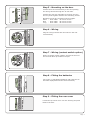
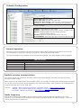
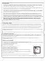
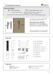
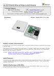
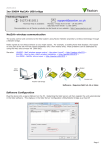
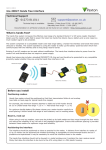
1
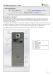
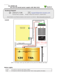
12/11/2012
Paxton
Ins-30169 Net2 PaxLock Mifare
Technical Support
01273 811011
[email protected]
Technical help is available:
Monday - Friday from 07:00 - 19:00 (GMT)
Saturday from 09:00 - 13:00 (GMT)
Documentation on all Paxton products can be found on our website - http://www.paxton.co.uk/
This wireless unit requires a Net2Air bridge
to communicate with the server PC.
Net2Air Site Surveyor (690-200).
This access control unit uses wireless
communication. It is recommended that a
Net2Air site surveyor is used to determine the
best position for the bridge and control units.
This unit requires Net2 v4.23 or later software.
Call Technical Support if you require advice.
Parts list
1
2
3
1) Front Lock Assembly
2) Rear Lock Assembly
3) Door Handle x 2
4) Mounting screw ( short ) x 2
4
5
6
2
5) Mounting screw ( medium ) x
6) Mounting screw ( long ) x 2
7
7) 8 mm Spindle
+
AA
+
AA
8
9
8) AA battery x 4
9) 4 mm Allen Key
-
-
Tools List
Power Drill
Drill bits 10 mm, 16 mm
Philips screwdriver
Small flat blade terminal screwdriver
Pencil
4mm Allen key (supplied)
Page 1
Installing the hardware
Step 1 - Marking out
75
70
65
60
55
50
45
40
35
30
25
20
15
10
5
0
5
10
15
20
25
30
35
40
45
50
55
60
65
70
Ø 16
105
Paxton
37
Ø 10
75
The lock case and cylinder (not supplied) must first be
fitted to the door, ensuring that a 22-24 mm diameter
hole is drilled for the follower (As shown on the
template provided).
Slide the spindle through the lock to allow the template
to locate over it. Ensure that the template is square to
the door edge by using the top and bottom ruler scales.
Mark the 2 x 10 mm, 1 x 16 mm holes. Remove the
template and repeat the procedure for the other side.
Step 2 - Drilling
Remove the lock if required and drill the 2 x 10 mm
holes for the mounting screws and 1 x 16 mm hole for
the wiring harness.
To ensure accuracy you should drill these holes from
both sides of the door towards the centre. This also
avoids the risk of damaging the door face when the drill
breaks through.
Step 3 - Contact switch (optional)
If a contact switch is to be fitted, an additional hole is
required in the edge of the door.
Drill a hole of the required size to receive the switch
assembly. This should intersect the 16 mm hole drilled
previously to take the wiring harness.
Feed the contact wires through the door to exit on the
inside.
Step 4 - Attach the Spindle
The spindle is locked into the front lock assembly by
means of a spring loaded pin.
Ensure that the spindle pin and the hole in the square
drive are in alignment before depressing the pin and
sliding the bar into the assembly. The pin will then latch
into the hole securing the spindle in place.
Page 2
Step 5 - Mounting on the door
Present the front lock assembly to the door passing
the wiring harness through the 16 mm hole.
Present the rear lock assembly to the door and join
the two parts together with the two mounting screws.
Mounting
Short Med
Long -
screws are provided in three lengths.
Door width 35 mm to 45 mm
Door width 40 mm to 50 mm
Door width 45 mm to 60 mm
Step 6 - Wiring
Plug the wiring harness into the socket in the rear
lock assembly.
Step 7 - Wiring (contact switch option)
Where a contact switch is fitted, connect the wires to
the terminal block provided on the pcb.
Step 8 - Fitting the batteries
Clip in the 4 x AA Alkaline batteries with reference to
the label displayed below the holder assembly.
Step 9 - Fitting the rear cover
Locate the top of the cover over the housing and push
flush to the door.
Page 3
Step 10 - Fitting the handles
Fit the two handles and secure with the grub screws provided.
Check the mechanical operation of the lock and that the
handles operate freely.
Software installation
The Net2 software should be loaded on the controlling PC and at least one Net2Air bridge configured to
communicate with the unit.
Full documentation is supplied with the Net2Air bridge unit and also on the website as follows:
XAN1051 - Installing Net2 software < http://paxton.info/1520 >
XIns-30084 - Net2Air USB bridge < http://paxton.info/926 >
XIns-30085 - Net2Air Ethernet bridge < http://paxton.info/920 >
Download the latest version of Net2 software at: http://paxton.info/1438 before commissioning this product.
The current specification for compatible PC hardware, network and operating systems is available on our
website at the following link: http://paxton.info/720
Some of the Net2 features (e.g. Fire alarm integration, Anti-passback, Lockdown) are not available on this
product as wireless communication is not suitable for data critical applications.
Enrolling a PaxLock
A PaxLock must bind to a Net2Air bridge before it will enrol itself onto the Net2 system. The term 'bind' is
used to denote the fixed relationship between a wireless unit and its bridge.
1. Create a user record in the database and assign a Net2 token to the user. (This record can be deleted after
the installation is complete.)
2. You must now wake up the PaxLock by using the front push button.
3. Present the user token to the PaxLock.
4. The Red and Green LED's will flash alternately while the unit configures.
The PaxLock transmits the number and waits for a response from Net2. If more than one bridge replies, the
unit checks the signal strength and selects the strongest bridge to communicate with. The Net2 software
confirms that the token number is in the database and registers the PaxLock/bridge binding. The LED's will
go out when the process has finished.
The software must be in commissioning mode which is the default setting. If this has been turned off it must
be enabled in the Server Configuration Utility.
An entry is then made on the Doors screen and a special icon is used to denote the wireless connection.
Net2 has NO PaxLock detection function. It is recognised that there could be security issues if the
wireless units were detectable from outside the site. During installation, a PaxLock unit binds to a Net2Air
bridge which will then only talk to registered units.
Devices cannot be added to the system if commissioning mode is disabled.
Page 4
Software Configuration
Door name: Name the Door.
Door open time: Set the door open time.
Unlock the Door during: Holds the door unlocked during this
timezone. - Set to 'At No Time' for normal user operation.
Reader: Local settings for the reader.
Output: Configures the lock for timed release or toggle mode.
Alarm: Enables/Disables the door alarm functions.
(requires contact switch)
Events: Shows the events for this control unit only.
Access Rights: Lists users who have access through this door.
Normal Operation
Presenting a valid user token to the unit will cause the LED to briefly flash Green and the door will unlock.
The presentation of a barred or unknown user token is indicted by a Red LED display.
The external handle is only engaged once access has been granted. The inside handle is always engaged.
LED indications
Green flash
A valid user card has been presented and the handle is engaged
Red flash
An invalid user card has been presented - No access granted
Red and Green flash together
The unit is not bound to a bridge.
Red and Green flash alternately
The unit is configuring - Please wait.
Net2Air wireless communication
The access control unit connects to the Net2 system using Paxton Net2Air proprietary wireless technology
through a Net2Air bridge.
Radio signals do not always behave as you might expect. For example, a mobile phone that displays a full signal
on one part of the site will lose signal completely only a few metres away. These problems can be addressed by
using the Net2 site surveyor kit (690-200).
See also: XAN1095 - Net2 wireless access control - How does it work? < http://paxton.info/974 >
X
AN1096 - How to plan a Net2 wireless installation < http://paxton.info/975 >
X
Ins-30096 - Net2Air site surveyor < http://paxton.info/1015 >
Radio frequency
This product should not be installed within 3 metres of other wireless equipment operating on a 2.4Ghz
frequency. To ensure optimum performance other wireless networks should avoid WiFi channels 1, 2 and 3 to
reduce the possibility of interference.
Page 5
Sleep mode
The PaxLock is a standalone unit and stays asleep while there is no user activity. The Net2 server cannot wake
up the unit. If the PIR is activated or the front button is pressed, it powers up the reader circuits in readiness
for a token read. Should nothing occur within 3 seconds, the unit will go back to sleep.
If a token is read, then the PaxLock moves into full operation. The token number is checked against the stored
database and access is granted or denied as per a standard Net2 control unit.
The PaxLock now sends this data via its Net2Air bridge connection to the Net2 server software. If any updates
need to be sent to the unit, including changes to the user data, these are transmitted back. The unit will then
go back to sleep waiting for further activity.
After 1 hour of inactivity, the PaxLock will send a heartbeat to the Net2 PC which responds with any updates.
This keeps the PaxLock updated even when there is no activity at the door and maximises battery life.
During the 1 hour sleep period, any changes made at the PC will not be received. If an immediate
update is required, the unit must be woken up by pressing the front button or presenting a user card.
Where a door is held unlocked by software, it will still receive updates every hour. To force an
immediate update, the unit must by activated by pressing the front button. A card can then be
presented to initiate the update request.
Low power mode
Low Power mode is available as a global setting in the Net2 server configuration utility or on individual Doors
screens. It is very useful for units that require low activity but have a high rate of passing traffic (e.g. corridor).
In low power mode the PaxLock must be woken up by pressing the front button. This ensures that incidental
handle or PIR activity does not cause an unnecessary drain on battery power or communications activity.
If woken, the PaxLock will initiate a transmission if it has been asleep for more than 1 hour. It will always initiate
an update every six hours.
Low battery warning
As the battery voltage falls the unit will update the Net2 server with its battery condition. This voltage level is
displayed as a coloured battery icon alongside the door in the Doors screen. When the batteries approach the
end of their life an Event is sent to Net2.
Using Net2 Trigger and Actions, an email or text message can be sent to a staff member or engineer to
schedule a battery change.
Battery replacement
1. Remove the inside handle from the door by removing the securing grub screw.
2. Remove the cover by holding the bottom edge and pulling it towards you. The cover will lift off at the top when
the bottom edge is clear of the housing.
3. Remove and replace batteries.
4. Refit the cover and handle.
Only to be used with alkaline batteries.
Recovery from a flat battery
Should the battery pack become discharged, the latch will no longer function.
This could be in the locked or unlocked state.
Holding a PP3 9V battery up to the contacts on the bottom of the unit will allow
the circuitry to operate normally.
A valid user card can then be used to open the door to access the batteries.
-ve +ve
Where the lock has a key override, this will always be available to unlock the door and gain entry.
Page 6
PaxLock reset
The PaxLock holds address information for the bridge that it is bound to. This will cause
problems if the unit is to be used on another system.
The unit requires a hardware reset to clear its bridge information. This is achieved as follows:
1. Remove the inside handle from the door by loosening the securing grub screw.
2. Remove the cover by holding the bottom edge and pulling it towards you. The cover will lift
off at the top when the bottom edge is clear of the housing.
3. Locate the red reset button at the top of the unit.
4. Hold the button down and wake up the unit by pressing the front push button.
The unit will give a beep when the reset has started. You can now release the reset button.
5. The Red and Green LED's will both flash until the process has finished.
6. Refit the cover and handle.
7. You can now enrol the unit.
Specifications
Features
Min
Max
Number of Cards
10,000
250
Access levels
64
Time zones
Door open time
60 secs
1 sec
10
ACU's per Net2Air bridge - Recommended
200
Net2Air bridge per system
Net2Air wireless range
20 m
Events stored in ACU with no server connection
3,584
Environment
Min
Max
4 x AA Alkaline
Battery type
Typical battery life
Operating temperature - Battery limits
2 years or 30,000 ops
3 years or 60,000 ops
0 °C
+ 55 °C
IPX4
External use
Vandal resistance
Reader/Keypad module (required space on door)
Total outside dimensions (includes handle clearance)
Read Range
Max = Low power mode
No
Low
6V DC
Voltage
Dimensions
Use site surveyor
Width
Height
Depth
40 mm
324 mm
35 mm
160 mm
324 mm
100 mm
Min
Max
Mifare 1K
20 mm
Mifare 4K
20 mm
Mifare Desfire
5 mm
The declaration of conformity is available on request. Contact details are provided at:
http://paxton.info/596
The Net2 PaxLock is EN1634-1:2008 FD30 and FD60 Fire resistant.
This product is not suitable for retail sale. All warranties are invalid if this product is not installed by a competent person.
Page 7