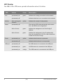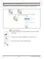
1
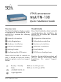
UTN Scannerserver
myUTN-130
Quick Installation Guide
Overview [en]
Überblick [de]
This Quick Installation Guide provides
a description of the installation of the
myUTN-130. It contains the following
information:
Dieser Quick Installation Guide beinhaltet
eine Beschreibung der Installation des
myUTN-130. Sie erhalten die folgenden
Informationen:
General Information
Allgemeine Information
Safety Regulations
Sicherheitsvorschriften
Hardware Installation
Hardware-Installation
Software Installation
Software-Installation
Getting Started
Erste Schritte
Configuring the UTN server
UTN-Server konfigurieren
Please note the table of contents on
page 3. Should you have any further
questions, please contact our support
hotline.
℡
@
Monday - Thursday
Friday
+49 (0)521 94226-44
Beachten Sie das Inhaltsverzeichnis auf
Seite 17. Falls Sie noch Fragen haben,
kontaktieren Sie unsere SupportHotline.
8:00 a.m. to 4:45 p.m. and
8:00 a.m. to 3:15 p.m. (CET)
[email protected]
Quick Installation Guide
1
Date of Manufacture
The serial number includes the date of manufacture.
The serial number can be found on the type plate.
2
Quick Installation Guide
2 General Information . . . . . . . . . . . . . . . . . . . . . . . . . . . . . . 4
Purpose . . . . . . . . . . . . . . . . . . . . . . . . . . . . . . . . . . . . . . . . . . . . . . . . . .4
Scope of Supply . . . . . . . . . . . . . . . . . . . . . . . . . . . . . . . . . . . . . . . . . .4
Technical Data . . . . . . . . . . . . . . . . . . . . . . . . . . . . . . . . . . . . . . . . . . .5
LED Display . . . . . . . . . . . . . . . . . . . . . . . . . . . . . . . . . . . . . . . . . . . . . .6
Table of Contents
2 Safety Regulations . . . . . . . . . . . . . . . . . . . . . . . . . . . . . . . 7
2 Hardware Installation. . . . . . . . . . . . . . . . . . . . . . . . . . . . . 8
2 Software Installation . . . . . . . . . . . . . . . . . . . . . . . . . . . . . 9
2 Getting Started: SEH UTN Manager . . . . . . . . . . . . . . . 10
Starting the SEH UTN Manager . . . . . . . . . . . . . . . . . . . . . . . . . .
Assigning an IP Address to the UTN Server . . . . . . . . . . . . . .
Adding the UTN Server to the Selection List . . . . . . . . . . . . .
Connecting the USB Scanner to the Client . . . . . . . . . . . . . . .
11
12
13
14
2 Configuring the UTN server . . . . . . . . . . . . . . . . . . . . . . 15
Quick Installation Guide
[en]
3
General Information
Purpose
The UTN server ‘myUTN-130‘ allows you to access a non-network-ready USB
scanner in the network. The USB scanner will be connected to the USB port of
the myUTN-130. The access is controlled via the software tool ‘SEH UTN
Manager‘.
The SEH UTN Manager is installed on all clients that are intended to access USB
scanners in the network. The SEH UTN Manager shows the availability of all USB
scanners in the network and establishes a connection between the client and the
USB scanner.
The administration of the myUTN-130 is done via the ‘myUTN Control Center‘.
Scope of Supply
Please check the package content before getting started:
4
UTN server
myUTN-130 (Scannerserver)
Quick
Installation
Guide
The Quick Installation Guide provides a brief
description of the installation of the myUTN-130.
(This document)
Power pack
External power pack
[en]
Quick Installation Guide
Technical Data
1) Link LED (green)
2) Activity LED (yellow)
3) Status LED (green)
4) Power LED (yellow)
5) LED for the USB port (green/
orange)
Front view
6) Network connector (RJ-45) for
1000BaseT, 100BaseTX and
10BaseT
7) USB port for the connection of a
USB scanner
8) Status/reset button
9) Connector for the included power
pack
Rear view
Properties
Values
Network connection
logical:
physical:
- 10BaseT/100BaseTX/1000BaseT (IEEE 802.3)
- RJ-45 (S/UTP Cat. 5)
Device connection
- 1 x USB scanner (via USB 2.0 HS)
Current input
- 300 mA @ 12 VDC (without load)
- 600 mA @ 12 VDC (with full load on the USB port)
Operating environment
- Ambient temperature:
- Relative humidity:
Dimensions
- Width:
- Height:
- Depth:
- Weight:
Quick Installation Guide
5 - 40 °C
20 - 80 %
140 mm
32 mm
99 mm
140 g
[en]
5
LED Display
The LEDs of the UTN server provide information about its status.
LED
Action
Color
Description
permanently on
green
Indicates an existing connection to the network.
permanently off
-
Indicates that there is no connection to the network.
Activity
blinks at irregular
intervals
yellow
Indicates the receipt of data packets.
Status
permanently off
-
If the activity LED blinks periodically at the same
time, the BIOS mode is signalized.
blinks 3 times
green
Indicates the assignment of a ZeroConfig IP
address.
blinks 2 times
green
Indicates the assignment of an IP address that
does not correspond to 0.0.0.0 or that comes from
outside the ZeroConf range.
permanently on
yellow
Indicates that the device is powered.
permanently off
-
Indicates that the device is not powered.
permanently off
-
No USB scanner is connected to the USB port.
permanently on
green
A USB scanner is connected to the USB port.
permanently on
orange
The USB scanner is connected to the USB port.
Link
Power
USB port
6
[en]
Quick Installation Guide
Safety Regulations
UTN server are network devices for use in office environments. The myUTN-130 is
designed for the integration of USB scanners into TCP/IP networks.
Before starting the initial setup procedure and during the operation of the UTN
server, please note the following safety regulations. Their purpose is to protect
yourself and others from personal injuries, and avoid damage to the equipment.
Read the documentation and make sure that your system meets the
requirements listed therein.
Avoid contact with humidity or liquids.
The device must only be connected and operated if it is in perfect condition.
Make sure that no-one steps on or stumbles over the cables.
Do not connect a telephone cable to the RJ-45 connector. The RJ-45
connector may only be connected to SELV voltages. For the connection to the
RJ-45 connector only S/UTP cabling (category 5 or better) may be used. The
shielding must fit flushly to the connector.
The device must only be operated using the power pack included in the
package.
Only use a certified USB cable (< 3 m) listed at www.usb.org.
Do not open the housing. Do not put objects on top of the housing. The device
must be placed on a solid surface with no vibration.
Quick Installation Guide
[en]
7
Hardware Installation
A USB scanner can be connected directly to the UTN server (myUTN-130).
Proceed as follows:
1. Connect the UTN server and the USB scanner with the USB
data cable.
2. Connect the network cable (RJ-45) to the UTN server.
3. Connect the power cord to the UTN server.
8
[en]
Quick Installation Guide
Software Installation
The software tool SEH UTN Manager organizes the access of the USB scanner. The
SEH UTN Manager is installed on all clients that are intended to access USB
scanners in the network.
The SEH UTN Manager is available in two versions:
Single-User Version (SEH UTN Manager)
Multi-User Version (SEH UTN Manager + SEH UTN Service)
A major difference between the single-user version and the multi-user version is
the Windows service ’SEH UTN Service’. A detailed description can be found in the
myUTN User Manual.
Make sure that:
- The installation of the SEH UTN Manager is suitable for Windows XP and
later.
- The installation can only be carried out by Windows users with
administrative rights.
First, you have to download the installation file for the SEH UTN Manager from
the homepage of SEH Computertechnik GmbH:
http://www.seh-technology.com/products/usb-device-servers/products/
myutn-130-downloads.html
Scan this QR code using your smart phone to get direct access to the homepage.
Proceed as follows:
1. Start the installation file.
2. Follow the installation routine.
The SEH UTN Manager is installed on your client.
Quick Installation Guide
[en]
9
Getting Started: SEH UTN Manager
After the SEH UTN Manager is started, the network will be scanned for connected
UTN servers. The network range to be scanned is freely definable.
After the network scan all UTN servers found – together with the connected
devices – will be shown in the 'network list'. The preferred devices will be selected
and added to the 'selection list'. The devices in the selection list can be connected
to the client.
This chapter describes the first steps with the program.
’Starting the SEH UTN Manager’
11
’Assigning an IP Address to the UTN Server’
’Adding the UTN Server to the Selection List’
’Connecting the USB Scanner to the Client’
12
13
14
Detailed information on how to use the SEH UTN Manager can be found
in the Online Help. To start the Online Help, select Help – Online Help
from the menu bar.
Client and UTN server communicate via the UTN port 9200. This port must not be
blocked by a firewall. If necessary, you can change the port number and/or use a
secure UTN SSL port. A detailed description can be found in the myUTN User
Manual.
10
[en]
Quick Installation Guide
Starting the SEH UTN Manager
Start the SEH UTN Manager on your client via the Windows start menu.
(Start --> Programs --> SEH Computertechnik GmbH --> SEH UTN Manager)
During the initial configuration, client and UTN server must be assigned to the
same local network segment.
Quick Installation Guide
[en]
11
Assigning an IP Address to the UTN Server
Once the UTN server is connected to the network, it checks whether an IP address
can be obtained from the boot protocols BOOTP or DHCP. If this is not the case,
the UTN server assigns itself an IP address via ZeroConf from the address range
(169.254.0.0/16) which is reserved for ZeroConf.
The UTN servers found by the program will be displayed in the network list. You can
change the TCP/IP parameters of the UTN server.
Proceed as follows:
1. Confirm the note dialog ’Your Selection List seems to be empty’ by clicking
Yes.
If no note dialog is available and the main dialog appears, select Selection List – Edit
from the menu bar.
2.
3.
4.
5.
12
The Edit Selection List dialog appears.
Select the UTN server from the network list.
Select Set IP Address from the shortcut menu.
The Set IP Address dialog appears.
Enter the relevant TCP/IP parameters.
Click OK.
The settings are saved.
[en]
Quick Installation Guide
Adding the UTN Server to the Selection List
In order to connect a UTN server to a client, you must assign the UTN server to
the selection list. Put together a selection list with your preferred UTN servers.
1.
2.
3.
4.
Proceed as follows:
Select Selection List – Edit from the menu bar.
The Edit Selection List dialog appears.
Select the UTN server from the network list.
Click Add.
Click OK.
The UTN servers are shown in the selection list.
You can extend the search for UTN servers to any network range. To do this, change the
search parameters for the network scan via the Options dialog in the Program menu.
Quick Installation Guide
[en]
13
Connecting the USB Scanner to the Client
The USB scanners in the selection list can be connected to the client.
Make sure that:
- All provisions (driver installation, etc.) necessary to operate the device locally
(i.e. connected directly to the client) have been met on the client. Ideally, the
device has been connected and operated on the client locally according to
the instructions of the manufacturer.
- The device is not connected to another client. A device that was made
available by the UTN server can only be used by one network participant at a
time.
Proceed as follows:
1. Highlight the device in the selection list.
2. Select Device – Activate from the menu bar.
The connection will be established.
Close the connection to the device when the device is no longer needed. Select
Device – Deactivate from the menu bar.
14
[en]
Quick Installation Guide
Configuring the UTN server
The UTN server can be configured and monitored via the myUTN Control Center.
The myUTN Control Center is stored in the UTN server and can be launched by
means of an Internet browser (Internet Explorer, Firefox, Safari).
Proceed as follows:
1. Open your browser.
2. Enter the IP address of the UTN server as the URL.
The myUTN Control Center will be displayed in the browser.
If the myUTN Control Center is not displayed, check the proxy settings of your browser.
Detailed information about the configuration of the UTN server
can be found in the Online Help of the myUTN Control Center.
To start the Online Help, click the ‘?‘ icon.
Quick Installation Guide
[en]
15
16
[en]
Quick Installation Guide
2 Allgemeine Information . . . . . . . . . . . . . . . . . . . . . . . . . 18
Verwendungszweck . . . . . . . . . . . . . . . . . . . . . . . . . . . . . . . . . . . .
Lieferumfang . . . . . . . . . . . . . . . . . . . . . . . . . . . . . . . . . . . . . . . . . . .
Technische Daten . . . . . . . . . . . . . . . . . . . . . . . . . . . . . . . . . . . . . .
LED-Anzeige . . . . . . . . . . . . . . . . . . . . . . . . . . . . . . . . . . . . . . . . . . .
18
18
19
20
Inhaltsverzeichnis
2 Sicherheitsvorschriften . . . . . . . . . . . . . . . . . . . . . . . . . . 21
2 Hardware-Installation . . . . . . . . . . . . . . . . . . . . . . . . . . . 22
2 Software-Installation . . . . . . . . . . . . . . . . . . . . . . . . . . . . 23
2 Erste Schritte mit dem SEH UTN Manager . . . . . . . . . 24
SEH UTN Manager starten. . . . . . . . . . . . . . . . . . . . . . . . . . . . . . .
UTN-Server eine IP-Adresse zuweisen . . . . . . . . . . . . . . . . . . .
UTN-Server der Auswahlliste hinzufügen . . . . . . . . . . . . . . . .
USB-Scanner mit Client verbinden . . . . . . . . . . . . . . . . . . . . . .
25
26
27
28
2 UTN-Server konfigurieren. . . . . . . . . . . . . . . . . . . . . . . . 29
Quick Installation Guide
[de]
17
Allgemeine Information
Verwendungszweck
Der UTN-Server ‘myUTN-130‘ erlaubt das Bereitstellen von einem nichtnetzwerkfähigen USB-Scanner für mehrere Netzwerkteilnehmer. Dazu wird der
USB-Scanner an den USB-Port des myUTN-130 angeschlossen. Die
Zugriffsverteilung erfolgt über das Software-Tool ‘SEH UTN Manager‘.
Der SEH UTN Manager wird auf alle Clients installiert, die auf im Netzwerk
bereitgestellte USB-Scanner zugreifen sollen. Der SEH UTN Manager zeigt die
Verfügbarkeit aller im Netzwerk eingebundenen USB-Scanner an und stellt die
Verbindung zwischen Client und USB-Scanner her.
Die Verwaltung des myUTN-130 erfolgt über das ‘myUTN Control Center‘.
Lieferumfang
Bitte überprüfen Sie den Packungsinhalt auf Vollständigkeit, bevor Sie die
Installation beginnen:
18
UTN-Server
myUTN-130 (Scannerserver)
Quick
Installation
Guide
Der Quick Installation Guide beinhaltet eine kurze
Beschreibung der Installation des myUTN-130.
(Dieses Dokument)
Netzteil
Externes Netzteil
[de]
Quick Installation Guide
Technische Daten
1) Link-LED (grün)
2) Activity-LED (gelb)
3) Status-LED (grün)
4) Power-LED (gelb)
5) LED für den USB-Port (grün/
orange)
Vorderansicht
6) Netzwerkanschluss (RJ-45) für
1000BaseT, 100BaseTX und
10BaseT
7) USB-Port für den Anschluss des
USB-Scanners
8) Status-/Reset-Taster
9) Anschluss für die Stromversorgung
über das mitgelieferte Netzteil
Rückansicht
Eigenschaften
Werte
Netzwerkanschluss
Logisch:
Physikalisch:
- 10BaseT/100BaseTX/1000BaseT (IEEE 802.3)
- RJ-45 (S/UTP Cat. 5)
Geräteanschluss
- 1 x USB-Scanner (über USB 2.0 HS)
Stromaufnahme
- 300 mA bei 12 VDC (ohne Last)
- 600 mA bei 12 VDC (bei Volllast auf dem USB-Port)
Betriebsumgebung
- Umgebungstemperatur:
- Relative Luftfeuchtigkeit:
Abmessungen
- Breite:
140 mm
- Höhe:
32 mm
- Tiefe:
99 mm
- Gewicht: 140 g
Quick Installation Guide
[de]
5 - 40 °C
20 - 80 %
19
LED-Anzeige
Durch die Interpretation des LED-Leuchtverhaltens kann der Zustand des UTNServers ermittelt werden.
LED
Aktion
Farbe
Beschreibung
Dauer-An
grün
Signalisiert eine vorhandene Verbindung zum
Netzwerk.
Dauer-Aus
-
Signalisiert, dass keine Verbindung zum Netzwerk
besteht.
Activity
unregelmäßiges
Blinken
gelb
Signalisiert den Empfang von Datenpaketen.
Status
Dauer-Aus
-
Bei gleichzeitigem zyklischen Blinken der ActivityLED wird der BIOS-Modus signalisiert.
3 x Blinken
grün
Signalisiert die Vergabe einer ZeroConfig-IPAdresse.
2 x Blinken
grün
Signalisiert die Vergabe einer IP-Adresse, die nicht
0.0.0.0 entspricht oder aus dem Bereich
ZeroConfig kommt.
Dauer-An
gelb
Signalisiert, dass das Gerät mit Strom versorgt
wird.
Dauer-Aus
-
Signalisiert, dass das Gerät nicht mit Strom
versorgt wird.
Dauer-Aus
-
Es ist kein USB-Scanner am USB-Port
angeschlossen.
Dauer-An
grün
Es ist ein USB-Scanner am USB-Port
angeschlossen.
Dauer-An
orange
Der USB-Scanner am USB-Port ist eingebunden.
Link
Power
USB-Port
20
[de]
Quick Installation Guide
Sicherheitsvorschriften
UTN-Server sind Netzwerkgeräte für den Gebrauch in Büroumgebungen. Der
myUTN-130 dient dem Einbinden von USB-Scannern in TCP/IP-Netzwerken.
Beachten Sie vor Inbetriebnahme und beim Betrieb des UTN-Servers die
folgenden Sicherheitsvorschriften, um sich und andere vor Personenschäden zu
schützen sowie Beschädigungen am Gerät zu vermeiden.
Lesen Sie die Dokumentation und stellen Sie sicher, dass Ihr System den
aufgeführten Anforderungen entspricht.
Das Gerät darf nicht mit Feuchtigkeit oder Flüssigkeit in Berührung kommen.
Das Gerät darf nur in unversehrtem Zustand angeschlossen und betrieben
werden.
Verlegen Sie alle Kabel so, dass niemand darauf treten oder darüber stolpern
kann.
Schließen Sie keine Telefonleitungen an den RJ-45-Stecker an. An diesen darf
nur Sicherheitskleinspannung angeschlossen werden. Verwenden Sie für den
Anschluss an den RJ-45 Stecker nur S/UTP-Kabel (Kategorie 5 oder besser).
Kabelschirm und Steckerschirm des Kabels müssen flächig verbunden sein.
Das Gerät darf nur mit dem mitgelieferten Netzteil betrieben werden.
Verwenden Sie als USB-Kabel ein zertifiziertes USB-Kabel (< 3 m), das unter
www.usb.org gelistet ist.
Öffnen Sie nicht das Gehäuse. Stellen Sie keine Gegenstände auf das Gehäuse.
Das Gerät muß auf einer stabilen, vibrationsarmen Oberfläche stehen.
Quick Installation Guide
[de]
21
Hardware-Installation
Am UTN-Server (myUTN-130) kann ein USB-Scanner direkt angeschlossen
werden.
Gehen Sie wie folgt vor:
1. Verbinden Sie den UTN-Server und den USB-Scanner mit dem
USB-Datenkabel.
2. Verbinden Sie das Netzwerkkabel (RJ-45) mit dem UTN-Server.
3. Verbinden Sie das Netzkabel mit dem UTN-Server.
22
[de]
Quick Installation Guide
Software-Installation
Die Zugriffsverteilung des USB-Scanners wird über das Software-Tool SEH UTN
Manager organisiert. Der SEH UTN Manager wird auf alle Clients installiert, die
auf im Netzwerk bereitgestellte USB-Scanner zugreifen sollen.
Der SEH UTN Manager ist in zwei Varianten verfügbar:
Single-User-Variante (SEH UTN Manager)
Multi-User-Variante (SEH UTN Manager + SEH UTN Service)
Wesentlicher Unterschied zwischen der Single-User- und der Multi-User-Variante
ist der Windows-Dienst ’SEH UTN Service’. Detaillierte Beschreibungen finden Sie
in der myUTN-Benutzerdokumentation.
Stellen Sie folgende Punkte sicher:
- Die Installation des SEH UTN Managers ist für Windows XP und höher
geeignet.
- Die Installation kann ausschließlich durch Windows-Benutzer mit
administrativen Rechten durchgeführt werden.
Bitte laden Sie zuerst die Installationsdatei für den SEH UTN Manager von der
SEH Computertechnik GmbH-Homepage:
http://www.seh.de/produkte/usb-device-server/products/
myutn-130-downloads.html
Scannen Sie diesen QR-Code mit Ihrem Smartphone, um direkt zur Homepage zu gelangen.
Gehen Sie wie folgt vor:
1. Starten Sie die Installationsdatei.
2. Folgen Sie der Installationsroutine.
Der SEH UTN Manager wird auf Ihrem Client installiert.
Quick Installation Guide
[de]
23
Erste Schritte mit dem SEH UTN Manager
Nach dem Start des SEH UTN Managers wird das Netzwerk nach angeschlossenen
UTN-Servern gescannt. Der zu scannende Netzwerkbereich ist frei definierbar.
Nach dem Netzwerkscan werden alle gefundenen UTN-Server und deren
angeschlossene Geräte in der 'Netzwerkliste' angezeigt. Die benötigten Geräte
werden ausgewählt und der 'Auswahlliste' hinzugefügt. Die in der Auswahlliste
aufgeführten Geräte können dann mit dem Client verbunden werden.
Dieses Kapitel informiert über die ersten Handlungsschritte mit dem Programm.
’SEH UTN Manager starten’
25
’UTN-Server eine IP-Adresse zuweisen’
26
’UTN-Server der Auswahlliste hinzufügen’
27
’USB-Scanner mit Client verbinden’
28
Detaillierte Informationen zur Bedienung des SEH UTN Managers
entnehmen Sie der Online Hilfe. Um die Online Hilfe zu starten, wählen
Sie im Menü Hilfe den Befehl Online Hilfe.
Client und UTN-Server kommunizieren über den UTN-Port 9200. Dieser Port darf
nicht durch eine Sicherheitssoftware (Firewall) blockiert werden. Bei Bedarf kann die
Portnummer geändert werden und/oder ein sicherer UTN-SSL-Port verwendet
werden. Detaillierte Beschreibungen finden Sie in der myUTNBenutzerdokumentation.
24
[de]
Quick Installation Guide
SEH UTN Manager starten
Starten Sie auf Ihrem Client den SEH UTN Manager über das WindowsStartmenü.
(Start --> Programme --> SEH Computertechnik GmbH --> SEH UTN Manager)
Während der Erstkonfiguration müssen Client und UTN-Server demselben lokalen
Netzwerksegment zugeordnet sein.
Quick Installation Guide
[de]
25
UTN-Server eine IP-Adresse zuweisen
Nachdem der UTN-Server an das Netzwerk angeschlossen ist, überprüft der UTNServer, ob er eine IP-Adresse über die Bootprotokolle BOOTP oder DHCP erhält. Ist
das nicht der Fall, gibt sich der UTN-Server über ZeroConf selbst eine IP-Adresse
aus dem für ZeroConf reservierten Adressbereich (169.254.0.0/16).
Die vom Programm gefundenen UTN-Server werden in der Netzwerkliste angezeigt.
Sie haben die Möglichkeit, die TCP/IP-Parameter am UTN-Server zu ändern.
Gehen Sie wie folgt vor:
1. Bestätigen Sie den Hinweisdialog ’Auswahlliste ist leer’ mit Ja.
Falls kein Hinweisdialog vorhanden ist und der Hauptdialog angezeigt wird, wählen Sie
im Menü Auswahlliste den Befehl Bearbeiten.
Der Dialog Auswahlliste bearbeiten erscheint.
2. Markieren Sie den UTN-Server in der Netzwerkliste.
3. Wählen Sie IP-Adresse definieren im Kontextmenü.
Der Dialog IP-Adresse definieren erscheint.
4. Geben Sie die entsprechenden TCP/IP-Parameter ein.
5. Wählen Sie die Schaltfläche OK an.
Die Einstellungen werden gespeichert.
26
[de]
Quick Installation Guide
UTN-Server der Auswahlliste hinzufügen
Um einen UTN-Server mit dem Client zu verbinden, muss der UTN-Server der
Auswahlliste zugeordnet werden. Stellen Sie die Auswahlliste mit Ihren bevorzugt
genutzten UTN-Servern zusammen.
1.
2.
3.
4.
Gehen Sie wie folgt vor:
Wählen Sie im Menü Auswahlliste den Befehl Bearbeiten.
Der Dialog Auswahlliste bearbeiten erscheint.
Markieren Sie den UTN-Server in der Netzwerkliste.
Wählen Sie die Schaltfläche Hinzufügen an.
Wählen Sie die Schaltfläche OK an.
Die UTN-Server werden in der Auswahlliste angezeigt.
Die Suche nach UTN-Servern kann auf beliebige Netzwerkbereiche erweitert werden.
Ändern Sie hierzu die Suchparameter für den Netzwerkscan im Menü Programm über
den Dialog Optionen.
Quick Installation Guide
[de]
27
USB-Scanner mit Client verbinden
In der Auswahlliste aufgeführte USB-Scanner können mit dem Client verbunden
werden.
Stellen Sie folgende Punkte sicher:
- Auf dem Client sind alle Vorbereitungen (Treiberinstallation usw.) getroffen
worden, die notwendig wären, um das Gerät lokal (also direkt am Client
angeschlossen) zu betreiben. Idealerweise ist das Gerät zuvor lokal am Client
nach der Anleitung des Herstellers angeschlossen und betrieben worden.
- Das Gerät ist nicht bereits mit einem anderen Client verbunden. Ein über den
UTN-Server zur Verfügung gestelltes Gerät kann zeitgleich nur von einem
Netzwerkteilnehmer genutzt werden.
Gehen Sie wie folgt vor:
1. Markieren Sie das Gerät in der Auswahlliste.
2. Wählen Sie im Menü Gerät den Befehl Aktivieren.
Die Verbindung wird hergestellt.
Deaktivieren Sie die Verbindung zum Gerät, sobald Sie es nicht mehr benötigen.
Wählen Sie hierzu im Menü Gerät den Befehl Deaktivieren.
28
[de]
Quick Installation Guide
UTN-Server konfigurieren
Über das ’myUTN Control Center’ kann der UTN-Server konfiguriert und
überwacht werden. Das myUTN Control Center ist in dem UTN-Server
gespeichert und kann mit einem Internet-Browser (Internet Explorer, Firefox,
Safari) aufgerufen werden.
Gehen Sie wie folgt vor:
1. Öffnen Sie Ihren Browser.
2. Geben Sie als URL die IP-Adresse des UTN-Servers ein.
Das myUTN Control Center wird im Browser dargestellt.
Falls das myUTN Control Center nicht angezeigt wird, überprüfen Sie die ProxyEinstellungen Ihres Browsers.
Detaillierte Informationen zur Konfiguration des UTN-Servers
entnehmen Sie der Online Hilfe des myUTN Control Centers.
Um die Online Hilfe zu starten, wählen Sie das ‘?‘ Symbol an.
Quick Installation Guide
[de]
29
The latest version of the EC declaration of conformity can be downloaded from
the homepage of SEH Computertechnik GmbH:
http://www.seh-technology.com/services/ce-notification.html
30
Quick Installation Guide
Quick Installation Guide
31
Manufactured by:
SEH Computertechnik GmbH
Suedring 11
Scan this QR code (meCard)
using your smart phone.
33647 Bielefeld
Germany
Phone: +49 (0)521 94226-29
Fax: +49 (0)521 94226-99
Support: +49 (0)521 94226-44
Email: [email protected]
Web: http://www.seh.de
Document:
Type: Quick Installation Guide
Title: myUTN-130
Version: 1.0
Order number: MHAB-QI-myUTN130
Online Links to important Internet Resources:
Support Contacts and Information:
Sales Contacts and Information:
Downloads:
http://www.seh-technology.com/support
http://www.seh-technology.com/sales
http://www.seh-technology.com/services/
downloads.html
© 2011 SEH Computertechnik GmbH
All trademarks, registered trademarks, logos and product names are property of their respective owners.
This product uses ’Open Source Software’. For further information, please contact http://www.seh.de.
The product documentation gives you valuable information about your product.
Keep the documentation for further reference during the life cycle of the product.
32
Quick Installation Guide