1
SUPER
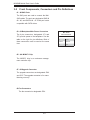
M28SAB/M28SAB-OEM
MOBILE RACK
USER'S GUIDE
Rev. 1.0
®
M28SAB Mobile Rack User's Guide
The information in this User’s Manual has been carefully reviewed and is believed to be accurate.
The vendor assumes no responsibility for any inaccuracies that may be contained in this document,
makes no commitment to update or to keep current the information in this manual, or to notify any
person or organization of the updates. Please Note: For the most up-to-date version of this
manual, please see our web site at www.supermicro.com.
Super Micro Computer, Inc. ("Supermicro") reserves the right to make changes to the product
described in this manual at any time and without notice. This product, including software and
documentation, is the property of Supermicro and/or its licensors, and is supplied only under a
license. Any use or reproduction of this product is not allowed, except as expressly permitted by
the terms of said license.
IN NO EVENT WILL SUPERMICRO BE LIABLE FOR DIRECT, INDIRECT, SPECIAL, INCIDENTAL,
SPECULATIVE OR CONSEQUENTIAL DAMAGES ARISING FROM THE USE OR INABILITY TO
USE THIS PRODUCT OR DOCUMENTATION, EVEN IF ADVISED OF THE POSSIBILITY OF
SUCH DAMAGES. IN PARTICULAR, SUPERMICRO SHALL NOT HAVE LIABILITY FOR ANY
HARDWARE, SOFTWARE, OR DATA STORED OR USED WITH THE PRODUCT, INCLUDING THE
COSTS OF REPAIRING, REPLACING, INTEGRATING, INSTALLING OR RECOVERING SUCH
HARDWARE, SOFTWARE, OR DATA.
Any disputes arising between manufacturer and customer shall be governed by the laws of Santa
Clara County in the State of California, USA. The State of California, County of Santa Clara shall
be the exclusive venue for the resolution of any such disputes. Super Micro's total liability for all
claims will not exceed the price paid for the hardware product.
California Best Management Practices Regulations for Perchlorate Materials: This Perchlorate
warning applies only to products containing CR (Manganese Dioxide) Lithium coin cells. “Perchlorate
Material-special handling may apply. See www.dtsc.ca.gov/hazardouswaste/perchlorate”
WARNING: Handling of lead solder materials used in this
product may expose you to lead, a chemical known to
the State of California to cause birth defects and other
reproductive harm.
Manual Revision 1.0
Release Date: June 7, 2011
Unless you request and receive written permission from Super Micro Computer, Inc., you may not
copy any part of this document.
Information in this document is subject to change without notice. Other products and companies
referred to herein are trademarks or registered trademarks of their respective companies or mark
holders.
Copyright © 2011 by Super Micro Computer, Inc.
All rights reserved.
Printed in the United States of America
ii
Safety Information and Technical Specifications
Table of Contents
Contacting Supermicro .......................................................................................iv
Returning Merchandise for Service.....................................................................v
Chapter 1 Safety Guidelines .................................................................... 1-1
1-1
ESD Safety Guidelines ................................................................................... 1-1
1-2
General Safety Guidelines .............................................................................. 1-1
1-3
An Important Note to Users ............................................................................ 1-2
Chapter 2 Introduction .............................................................................. 2-1
2-1
Overview ......................................................................................................... 2-1
2-2
Product Features ........................................................................................... 2-1
Operating Systems ..................................................................................... 2-1
Additional Information ..................................................................................... 2-2
Chapter 3 SAS-I28A Backplane Specifications ...................................... 3-1
3-1
Front Connectors and Jumpers ...................................................................... 3-1
3-2
Front Components, Connectors and Pin Definitions ...................................... 3-2
3-3
Front Jumper Locations and Pin Definitions ................................................... 3-3
Explanation of Jumpers .................................................................................. 3-3
3-4
Rear Connectors and LED Indicators ............................................................. 3-4
Chapter 4 Mobile Rack Installation Instructions .................................... 4-1
4-1
Shipping List.................................................................................................... 4-1
4-2
Tools Required ................................................................................................ 4-1
4-3
Other Parts ...................................................................................................... 4-1
4-4
Setup and Installation Steps ........................................................................... 4-2
4-5
General Safety Guidelines .............................................................................. 4-2
4-6
Before Accessing the Mobile Rack ................................................................. 4-2
4-7
Cooling Fan Installation .................................................................................. 4-3
Installing the Cooling Fan ............................................................................... 4-3
Fan Removal ................................................................................................... 4-3
4-8
Hard Drive Installation ..................................................................................... 4-4
4-9
Connect Data and Power Cables ................................................................... 4-6
4-10
Advanced Configuration .................................................................................. 4-6
iii
M28SAB Mobile Rack User's Guide
Contacting Supermicro
Headquarters
Address:
Super Micro Computer, Inc.
980 Rock Ave.
San Jose, CA 95131 U.S.A.
Tel:
+1 (408) 503-8000
Fax:
+1 (408) 503-8008
Email:
[email protected] (General Information)
[email protected] (Technical Support)
Web Site:
www.supermicro.com
Europe
Address:
Super Micro Computer B.V.
Het Sterrenbeeld 28, 5215 ML
's-Hertogenbosch, The Netherlands
Tel:
+31 (0) 73-6400390
Fax:
+31 (0) 73-6416525
Email:
[email protected] (General Information)
[email protected] (Technical Support)
[email protected] (Customer Support)
Asia-Pacific
Address:
Super Micro Computer, Inc.
4F, No. 232-1, Liancheng Rd.
Chung-Ho 235, Taipei County
Taiwan, R.O.C.
Tel:
+886-(2) 8226-3990
Fax:
+886-(2) 8226-3991
Web Site:
www.supermicro.com.tw
Technical Support:
Email:
[email protected]
Tel:
886-2-8226-1900
iv
Safety Information and Technical Specifications
Returning Merchandise for Service
A receipt or copy of your invoice marked with the date of purchase is required before any warranty service will be rendered. You can obtain service by calling your
vendor for a Returned Merchandise Authorization (RMA) number. When returning
to the manufacturer, the RMA number should be prominently displayed on the
outside of the shipping carton, and mailed prepaid or hand-carried. Shipping and
handling charges will be applied for all orders that must be mailed when service
is complete.
For faster service, RMA authorizations may be requested online (http://www.supermicro.com/support/rma/).
Whenever possible, repack the mobile rack in the original Supermicro carton, using
the original packaging material. If these are no longer available, be sure to pack the
mobile rack securely, using packaging material to surround the mobile rack so that
it does not shift within the carton and become damaged during shipping.
This warranty only covers normal consumer use and does not cover damages incurred in shipping or from failure due to the alteration, misuse, abuse or improper
maintenance of products.
During the warranty period, contact your distributor first for any product problems.
v
M28SAB Mobile Rack User's Guide
Notes
vi
Safety Information and Technical Specifications
Chapter 1
Safety Guidelines
To avoid personal injury and property damage, carefully follow all the safety steps
listed below when accessing your system or handling the components.
1-1
ESD Safety Guidelines
Electrostatic Discharge (ESD) can damage electronic components. To prevent damage to your system, it is important to handle it very carefully. The following measures
are generally sufficient to protect your equipment from ESD.
•
Use a grounded wrist strap designed to prevent static discharge.
•
Touch a grounded metal object before removing a component from the antistatic
bag.
•
Handle the mobile rack backplane by its edges only; do not touch its components, peripheral chips, memory modules or gold contacts.
•
When handling chips or modules, avoid touching their pins.
•
Put the card and peripherals back into their antistatic bags when not in use.
1-2
•
General Safety Guidelines
Always disconnect power cables before installing or removing any components
from the computer, including the backplane.
•
Disconnect the power cable before installing or removing any cables from the
backplane.
•
Make sure that the backplane is securely and properly installed on the motherboard to prevent damage to the system due to power shortage.
1-1
M28SAB Mobile Rack User's Guide
1-3
An Important Note to Users
All images and layouts shown in this user's guide are based upon the latest equipment and PCB revision available at the time of publishing. The card and equipment
you have received may or may not look exactly the same as the graphics shown
in this manual.
1-2
Safety Information and Technical Specifications
Chapter 2
Introduction
2-1
Overview
This manual has been written for system integrators, PC technicians and
knowledgeable PC users. It provides detailed information for the installation and
use of the M28SAB mobile rack.
The Supermicro M28SAB mobile rack showcases advanced technology innovations
in modular connectivity and data transferability and supplies reliable, effective, and
scalable solutions for tomorrow’s data communications industry.
2-2
Product Features
The M28SAB mobile rack includes the following:
•
Slim design: pocket-size (5-3/4” width x 3-3/8” height).
•
Supports a 8 x 2.5” small form factor hard disk drive.
•
Supports up to 5V/10A (average) and 12V/10A (average).
•
Supports SAS 2.0 and SATA III at 6 Gbps transfer speed.
Operating Systems
This mobile rack supports the following operating systems:
•
Windows 2000, Windows XP, Windows 7 and Windows 2003.
•
Linux: Red Hat and SuSE.
For the most current information on supported operating systems visit the
Supermicro Web site at www.supermicro.com.
2-1
M28SAB Mobile Rack User's Guide
Additional Information
The M28SAB mobile rack was designed for use in certain chassis and servers or
as an optional unit for storage expansion. Use the chassis or server manual for
installation instructions. Use the instructions listed in this manual to use the mobile
rack independent of a chassis.
The pictures or graphics shown in this user’s guide were based upon the latest revision available at the time of publication of this manual. The M28SAB mobile rack
may or may not look exactly the same as the graphics shown in this manual.
The availability of the SAS devices supported depends upon the readiness of firmware and hardware support.
The SAS-I28A mobile rack backplane has been designed to utilize the most upto-date technology available, providing your system with reliable, high-quality
performance.
This manual reflects SAS-I28A Revision 1.00, the most current release available at
the time of publication. Always refer to the Supermicro Web site at www.supermicro.
com for the latest updates, compatible parts and supported configurations.
2-2
Safety Information and Technical Specifications
Chapter 3
SAS-I28A Backplane Specifications
3-1
Front Connectors and Jumpers
17
A18
JSM2
A1
34
44
UPGRADE #2
2
6
5
JP47
JP61
1-2 WITH FAN
2-3 NO FAN
6
5
2
B18
JP61
3
SAS IN #4-#7
B1
Y2
1 FAN
12
JSM1
MH2
Y1
16
34
U40
44
B18
RP14
SAS IN #0-#3
ACT LED TEST
1
15
BAR CODE
13
+
+
1
+
3 JP62
4
R69
DESIGNED IN USA
B1
TP4 TP3
14
JP3
1
A1
JP62
1-2 WITH FAN
2-3 NO FAN
19
A18
33
18
JP54
12
1
23
1
22
23
JP46
1
MH1
UPGRADE #1
JP25: OH TEMP
OPEN 45 C
1-2 50 C
2-3 55 C
3
C84 JP25
1
9071 RST
C78
BPN-SASI28A
C77
1
+12V
REV 1.00
JP1
4
+5V
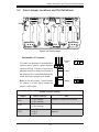
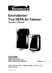
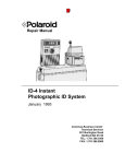
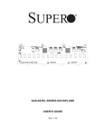
Figure 3-1: Front Connectors and Components
Front Connectors and Components
1. SAS IN #0 - #3: JSM1
6. MG9071 chip
2. SAS IN #4 - #7: JSM2
7. Upgrade connector #1: JP46
3. Power connector: JP1
8. Upgrade connector #2: JP47
4. Power connector: JP3
9. Fan connector: JP54
5. MG9071 chip
3-1
M28SAB Mobile Rack User's Guide
3-2
Front Components, Connectors and Pin Definitions
#1 - #2 SAS Ports
The SAS ports are used to connect the MiniSAS cables. The ports are designated SAS IN
#0 - #3, and SAS IN #4 - #7. Each port is also
compatible with SATA drives.
#3 - #4 Backplane Main Power Connectors
The 4-pin connectors, designated JP1 and
JP3, provide power to the backplane. See the
table on the right for pin definitions. Both of
these connectors must be used at the same
time.
#5. - #6. MG9071 Chip
The MG9071 chip is an enclosure management controller chip.
#7 - #8 Upgrade Connector
The upgrade connectors are designated JP46
and JP47. The upgrade connector is for manufacturing use only.
#9 Fan Connectors
The fan connector is designated JP54.
3-2
Backplane
Main Power
4-Pin Connectors
Pin#
Definition
1
+12V
2 and 3
Ground
4
+5V
Safety Information and Technical Specifications
3-3
Front Jumper Locations and Pin Definitions
A18
JSM2
A1
34
44
UPGRADE #2
2
UPGRADE #1
5
JP47
JP61
1-2 WITH FAN
2-3 NO FAN
6
5
2
B18
JP61
3
SAS IN #4-#7
B1
22
12
JSM1
A18
A1
23
MH2
1
33
23
1
JP61
6
JP46
1
MH1
Y1
Y2
34
U40
44
B18
RP14
SAS IN #0-#3
B1
TP4 TP3
JP54
ACT LED TEST
1 FAN
JP62
1-2 WITH FAN
2-3 NO FAN
BAR CODE
1
4
1
R69
DESIGNED IN USA
JP25: OH TEMP
OPEN 45 C
1-2 50 C
2-3 55 C
3
C84 JP25
JP25
1
9071 RST
+
3 JP62
+
+
JP62
JP3
1
+12V
C78
BPN-SASI28A
C77
REV 1.00
4
+5V
JP1
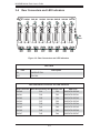
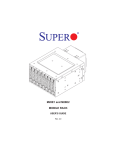
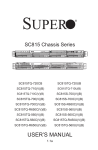
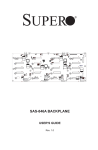
Figure 3-2: Front Jumper
Explanation of Jumpers
To modify the operation of the backplane,
jumpers can be used to choose between
optional settings. Jumpers create shorts
between two pins to change the function of
the connector. Pin 1 is identified with a square
solder pad on the printed circuit board.
Note: On two-pin jumpers, "Closed" means
the jumper is on and "Open" means the
3
2
1
3
2
1
Connector
Pins
Jumper
Setting
jumper is off the pins.
General Jumper Settings
Jumper
Jumper Settings
Note
JP61
1-2: Fan enabled
2-3: Fan disabled
Enables or disables the fan power.
JP62
1-2: Fan enabled
2-3: Fan disabled
Enclosure monitor enable/disable.
JP25
Open: 45o C
1-2: 50o C
2-3: 55oC
Allows the overheat temperature to be
adjusted.
3-3
M28SAB Mobile Rack User's Guide
3-4
Rear Connectors and LED Indicators
SAS #0 SAS #1 SAS #2
J1
J2
J3
#0
#1
J2
J1
J3
SAS #3 SAS #4 SAS #5 SAS #6 SAS #7
J4
J5
J6
J7
J8
#3
#2
#4
J6
J5
#5
#6
J7
#7
J8
J4
1
27
7
27
27
7
27
7
7
8
8
27
7
8
7
8
8
33
9
33
9
33
9
7
8
8
33
9
27
7
33
9
8
33
9
4
27
33
9
33
9
OH/DRIVE FAIL
27
D30
D31
D32
A
FAIL1
C A D33
ACT1
D32
D33
C
A D34
C
FAIL2
A D35
ACT2
A D36
C
D34
D35
FAIL3
A D38
A D37
C
C
ACT3
D36
D37
C A D39
FAIL4
C
ACT4
22
22
D40
A
FAIL5
D38
D39
C
D47
C
ACT0
22
A A
D31
C A
22
21
21
21
22
C
FAN FAIL
22
D9
A D30
FAIL0
21
21
21
22
21
21
22
D9
D47
D41
C A
C
ACT5
D40
D41
A D42
C
FAIL6
A D43
A D44
C
ACT6
FAIL7
D42
D43
D45
C
C
ACT7
D44
D45
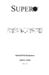
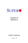
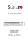
Figure 3-3: Rear Connectors and LED Indicators
Rear LEDs
LED
Description
D9
OH/DRIVE FAIL
D47
FAN FAIL
Rear SAS/SATA Connectors and LED Indicators
Rear Connector
Hard Drive Activity LED
Failure LED
SAS #0
D31
D30
SAS/SATA HDD #0
SAS #1
D33
D32
SAS/SATA HDD #1
SAS #2
D35
D34
SAS/SATA HDD #2
SAS #3
D37
D36
SAS/SATA HDD #3
SAS #4
D39
D38
SAS/SATA HDD #4
SAS #5
D41
D40
SAS/SATA HDD #5
SAS #6
D43
D42
SAS/SATA HDD #6
SAS #7
D45
D44
SAS/SATA HDD #7
3-4
SAS Drive
Safety Information and Technical Specifications
Chapter 4
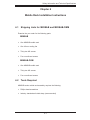
Mobile Rack Installation Instructions
4-1
Shipping Lists for M28SAB and M28SAB-OEM
Examine the your order for the following parts:
M28SAB
•
One M28SAB mobile rack
•
One 40 mm cooling fan
•
Thirty-two M3 screws
•
Four round-head screws
M28SAB-OEM
•
One M28SAB mobile rack
•
Thirty-two M3 screws
•
Four round-head screws
4-2
Tools Required
M28SAB series mobile rack assembly requires the following:
•
Phillips head screwdriver
•
Industry standard anti-static strap (recommended)
4-1
M28SAB Mobile Rack User's Guide
4-3
Other Parts
When using this mobile rack independent of a chassis, you may need the following parts.
•
Two 4-pin power cords to connect the mobile rack to a power supply.
•
SAS iPass cable, part numbers CBL-0108L (39 cm), CBL-0281L (75 cm) or
CBL-0294L-01 are used to connect the SAS ports to the motherboard or RAID
controller.
4-4
Setup and Installation Steps
Use the following list as a guide to set up and install the mobile rack. If this mobile
rack is to be installed in a chassis, use the instructions in the chassis manual.
Mobile Rack Chassis Installation
1. Unpack and examine system parts.
2. Review all system and safety guidelines.
3. M28SAB: Install the system fan as described in section 4-7 of this manual
(not required on M28SAB-OEM).
M28SAB-OEM: Reset jumper JP61 to "enable", pins 2 - 3, without the fan
connected.
4. Install the hard drives.
5. Connect data and power cables.
4-5
•
•
General Safety Guidelines
Always disconnect power cables before installing or removing any components
from the computer, including the backplane.
Disconnect the power cable before installing or removing any cables from the
mobile rack or backplane.
4-2
Safety Information and Technical Specifications
•
Make sure that the backplane is securely and properly installed on the motherboard to prevent damage to the system due to power shortage.
4-6
Before Accessing the Mobile Rack
Prior to Accessing the Mobile Rack
1. Power-down and power supply connected to the chassis or server. In addition, unplug all power cords from the wall outlet.
2. Disconnect all necessary cables and label the cables for easy identification.
3. Use a grounded wrist strap designed to prevent static discharge when handling components.
4. Save all screws and fasteners for later use.
5. Familiarize yourself with and follow the instructions in this section.
4-3
M28SAB Mobile Rack User's Guide
4-7
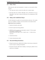
Cooling Fan Installation (M28SAB Only)
Installing the Cooling Fan
The M28SAB mobile rack includes a cooling fan (not required on M28SAB-OEM).
When using the M28SAB without installing the mobile rack in a larger unit such as
a chassis, a cooling fan must be installed on the mobile rack unit.
For more information on installing the mobile rack into a chassis or server, see the
documentation for your mobile rack or server. You can also visit our Web site at
http://www.supermicro.com.Installing the Cooling Fan on the Mobile Rack
1. Align the mounting holes on the fan with the mounting holes in the mobile
rack.
2. Attach the cooling fan cable to the fan connector.
3. Secure with two screws as illustrated.
Figure 4-1: Installing the Fan on the M28SAB Mobile Rack
Fan Removal
Removing the Cooling Fan from the Mobile Rack
1. Remove the fan cable from the mobile rack by gentlypulling the cable from
the backplane.
2. Remove the screws securing the fan to the mobile rack.
3. Pull the fan away from the rear of the mobile rack.
4-4
Safety Information and Technical Specifications
4-8
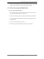
Hard Drive Installation
Each M28 mobile rack includes dummy trays that act as place holders for hard
drives. Before using the mobile rack, you must install hard drives into the drive
carriers. Hard drives are sold separately.
Release Tab
Hard Drive Tray Latch
Figure 4-2: Mobile Rack with Hard Drive Trays
Installing Hard Drives into the Mobile Rack
1. Press the release tabs to open the hard drive carrier latch.
2. Using the latch as a handle, pull the drive carrier from the hard drive.
!
Warning! Enterprise level hard disk drives are recommended for use
in Supermicro chassis and servers. For information on recommended
HDDs, visit the Supermicro Web site at www.supermicro.com
4-5
M28SAB Mobile Rack User's Guide
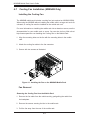
Hard Drive
Hard Drive Carrier
M3 Screws
Figure 4-3: Hard Drive and Hard Drive Tray
3. Place a 2.5" hard drive in the hard drive carrier.
4. Align the hard drives to the rear of the hard drive tray.
5. Secure the hard drive to the tray using four M3 screws (as illustrated).
6. Using the hard drive tray latch as a handle, slide the hard drive into the
mobile rack.
7. Close the hard drive tray handle to lock the hard drive into place.
8. Repeat steps 1-8 for each hard drive that you will install into the mobile rack.
4-6
Safety Information and Technical Specifications
4-9
Connect Data and Power Cables
Connecting the Cables
1. Connect the SAS cables to the mobile rack. A longer SAS cable may be
required (see the recommended cables listed earlier in this manual).
2. Connect the power cables from the chassis power supply. A power cable
extension may be required.
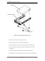
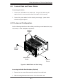
4-10 Advanced Configuration
Use the following instructions in the unlikely event that you must access the jumpers, buzzer, or other backplane components.
Remove
Screws
Remove
Screw
Mobile Rack
Casing
Remove
Screw
Figure 4-4: Mobile Rack and Rear Casing
Accessing the Mobile Rack Backplane (Optional)
1. Remove the two screws that secure the casing to the mobile rack.
2. Slide the casing downward and remove it from the mobile rack.
4-7
M28SAB Mobile Rack User's Guide
Notes
4-8
Safety Information and Technical Specifications
Disclaimer (cont.)
The products sold by Supermicro are not intended for and will not be used in life support systems, medical equipment, nuclear facilities or systems, aircraft, aircraft devices,
aircraft/emergency communication devices or other critical systems whose failure to perform be reasonably expected to result in significant injury or loss of life or catastrophic
property damage. Accordingly, Supermicro disclaims any and all liability, and should
buyer use or sell such products for use in such ultra-hazardous applications, it does so
entirely at its own risk. Furthermore, buyer agrees to fully indemnify, defend and hold
Supermicro harmless for and against any and all claims, demands, actions, litigation,
and proceedings of any kind arising out of or related to such ultra-hazardous use or
sale.
4-9